EP1418569A1 - Acoustic damper for exhaust system - Google Patents
Acoustic damper for exhaust system Download PDFInfo
- Publication number
- EP1418569A1 EP1418569A1 EP20030025475 EP03025475A EP1418569A1 EP 1418569 A1 EP1418569 A1 EP 1418569A1 EP 20030025475 EP20030025475 EP 20030025475 EP 03025475 A EP03025475 A EP 03025475A EP 1418569 A1 EP1418569 A1 EP 1418569A1
- Authority
- EP
- European Patent Office
- Prior art keywords
- exhaust
- noise
- exhaust chamber
- exhaust system
- resonator
- Prior art date
- Legal status (The legal status is an assumption and is not a legal conclusion. Google has not performed a legal analysis and makes no representation as to the accuracy of the status listed.)
- Withdrawn
Links
Images









Classifications
-
- F—MECHANICAL ENGINEERING; LIGHTING; HEATING; WEAPONS; BLASTING
- F01—MACHINES OR ENGINES IN GENERAL; ENGINE PLANTS IN GENERAL; STEAM ENGINES
- F01N—GAS-FLOW SILENCERS OR EXHAUST APPARATUS FOR MACHINES OR ENGINES IN GENERAL; GAS-FLOW SILENCERS OR EXHAUST APPARATUS FOR INTERNAL-COMBUSTION ENGINES
- F01N13/00—Exhaust or silencing apparatus characterised by constructional features
- F01N13/02—Exhaust or silencing apparatus characterised by constructional features having two or more separate silencers in series
-
- F—MECHANICAL ENGINEERING; LIGHTING; HEATING; WEAPONS; BLASTING
- F01—MACHINES OR ENGINES IN GENERAL; ENGINE PLANTS IN GENERAL; STEAM ENGINES
- F01N—GAS-FLOW SILENCERS OR EXHAUST APPARATUS FOR MACHINES OR ENGINES IN GENERAL; GAS-FLOW SILENCERS OR EXHAUST APPARATUS FOR INTERNAL-COMBUSTION ENGINES
- F01N1/00—Silencing apparatus characterised by method of silencing
- F01N1/02—Silencing apparatus characterised by method of silencing by using resonance
-
- F—MECHANICAL ENGINEERING; LIGHTING; HEATING; WEAPONS; BLASTING
- F01—MACHINES OR ENGINES IN GENERAL; ENGINE PLANTS IN GENERAL; STEAM ENGINES
- F01N—GAS-FLOW SILENCERS OR EXHAUST APPARATUS FOR MACHINES OR ENGINES IN GENERAL; GAS-FLOW SILENCERS OR EXHAUST APPARATUS FOR INTERNAL-COMBUSTION ENGINES
- F01N1/00—Silencing apparatus characterised by method of silencing
- F01N1/02—Silencing apparatus characterised by method of silencing by using resonance
- F01N1/04—Silencing apparatus characterised by method of silencing by using resonance having sound-absorbing materials in resonance chambers
-
- F—MECHANICAL ENGINEERING; LIGHTING; HEATING; WEAPONS; BLASTING
- F01—MACHINES OR ENGINES IN GENERAL; ENGINE PLANTS IN GENERAL; STEAM ENGINES
- F01N—GAS-FLOW SILENCERS OR EXHAUST APPARATUS FOR MACHINES OR ENGINES IN GENERAL; GAS-FLOW SILENCERS OR EXHAUST APPARATUS FOR INTERNAL-COMBUSTION ENGINES
- F01N1/00—Silencing apparatus characterised by method of silencing
- F01N1/06—Silencing apparatus characterised by method of silencing by using interference effect
-
- F—MECHANICAL ENGINEERING; LIGHTING; HEATING; WEAPONS; BLASTING
- F01—MACHINES OR ENGINES IN GENERAL; ENGINE PLANTS IN GENERAL; STEAM ENGINES
- F01N—GAS-FLOW SILENCERS OR EXHAUST APPARATUS FOR MACHINES OR ENGINES IN GENERAL; GAS-FLOW SILENCERS OR EXHAUST APPARATUS FOR INTERNAL-COMBUSTION ENGINES
- F01N1/00—Silencing apparatus characterised by method of silencing
- F01N1/08—Silencing apparatus characterised by method of silencing by reducing exhaust energy by throttling or whirling
- F01N1/084—Silencing apparatus characterised by method of silencing by reducing exhaust energy by throttling or whirling the exhaust gases flowing through the silencer two or more times longitudinally in opposite directions, e.g. using parallel or concentric tubes
-
- F—MECHANICAL ENGINEERING; LIGHTING; HEATING; WEAPONS; BLASTING
- F01—MACHINES OR ENGINES IN GENERAL; ENGINE PLANTS IN GENERAL; STEAM ENGINES
- F01N—GAS-FLOW SILENCERS OR EXHAUST APPARATUS FOR MACHINES OR ENGINES IN GENERAL; GAS-FLOW SILENCERS OR EXHAUST APPARATUS FOR INTERNAL-COMBUSTION ENGINES
- F01N1/00—Silencing apparatus characterised by method of silencing
- F01N1/08—Silencing apparatus characterised by method of silencing by reducing exhaust energy by throttling or whirling
- F01N1/089—Silencing apparatus characterised by method of silencing by reducing exhaust energy by throttling or whirling using two or more expansion chambers in series
-
- F—MECHANICAL ENGINEERING; LIGHTING; HEATING; WEAPONS; BLASTING
- F01—MACHINES OR ENGINES IN GENERAL; ENGINE PLANTS IN GENERAL; STEAM ENGINES
- F01N—GAS-FLOW SILENCERS OR EXHAUST APPARATUS FOR MACHINES OR ENGINES IN GENERAL; GAS-FLOW SILENCERS OR EXHAUST APPARATUS FOR INTERNAL-COMBUSTION ENGINES
- F01N1/00—Silencing apparatus characterised by method of silencing
- F01N1/24—Silencing apparatus characterised by method of silencing by using sound-absorbing materials
-
- G—PHYSICS
- G10—MUSICAL INSTRUMENTS; ACOUSTICS
- G10K—SOUND-PRODUCING DEVICES; METHODS OR DEVICES FOR PROTECTING AGAINST, OR FOR DAMPING, NOISE OR OTHER ACOUSTIC WAVES IN GENERAL; ACOUSTICS NOT OTHERWISE PROVIDED FOR
- G10K11/00—Methods or devices for transmitting, conducting or directing sound in general; Methods or devices for protecting against, or for damping, noise or other acoustic waves in general
- G10K11/16—Methods or devices for protecting against, or for damping, noise or other acoustic waves in general
- G10K11/172—Methods or devices for protecting against, or for damping, noise or other acoustic waves in general using resonance effects
-
- F—MECHANICAL ENGINEERING; LIGHTING; HEATING; WEAPONS; BLASTING
- F01—MACHINES OR ENGINES IN GENERAL; ENGINE PLANTS IN GENERAL; STEAM ENGINES
- F01N—GAS-FLOW SILENCERS OR EXHAUST APPARATUS FOR MACHINES OR ENGINES IN GENERAL; GAS-FLOW SILENCERS OR EXHAUST APPARATUS FOR INTERNAL-COMBUSTION ENGINES
- F01N13/00—Exhaust or silencing apparatus characterised by constructional features
- F01N13/18—Construction facilitating manufacture, assembly, or disassembly
- F01N13/1838—Construction facilitating manufacture, assembly, or disassembly characterised by the type of connection between parts of exhaust or silencing apparatus, e.g. between housing and tubes, between tubes and baffles
- F01N13/1844—Mechanical joints
- F01N13/185—Mechanical joints the connection being realised by deforming housing, tube, baffle, plate, or parts thereof
-
- F—MECHANICAL ENGINEERING; LIGHTING; HEATING; WEAPONS; BLASTING
- F01—MACHINES OR ENGINES IN GENERAL; ENGINE PLANTS IN GENERAL; STEAM ENGINES
- F01N—GAS-FLOW SILENCERS OR EXHAUST APPARATUS FOR MACHINES OR ENGINES IN GENERAL; GAS-FLOW SILENCERS OR EXHAUST APPARATUS FOR INTERNAL-COMBUSTION ENGINES
- F01N13/00—Exhaust or silencing apparatus characterised by constructional features
- F01N13/18—Construction facilitating manufacture, assembly, or disassembly
- F01N13/1838—Construction facilitating manufacture, assembly, or disassembly characterised by the type of connection between parts of exhaust or silencing apparatus, e.g. between housing and tubes, between tubes and baffles
- F01N13/1844—Mechanical joints
- F01N13/1855—Mechanical joints the connection being realised by using bolts, screws, rivets or the like
-
- F—MECHANICAL ENGINEERING; LIGHTING; HEATING; WEAPONS; BLASTING
- F01—MACHINES OR ENGINES IN GENERAL; ENGINE PLANTS IN GENERAL; STEAM ENGINES
- F01N—GAS-FLOW SILENCERS OR EXHAUST APPARATUS FOR MACHINES OR ENGINES IN GENERAL; GAS-FLOW SILENCERS OR EXHAUST APPARATUS FOR INTERNAL-COMBUSTION ENGINES
- F01N2210/00—Combination of methods of silencing
- F01N2210/02—Resonance and interference
-
- F—MECHANICAL ENGINEERING; LIGHTING; HEATING; WEAPONS; BLASTING
- F01—MACHINES OR ENGINES IN GENERAL; ENGINE PLANTS IN GENERAL; STEAM ENGINES
- F01N—GAS-FLOW SILENCERS OR EXHAUST APPARATUS FOR MACHINES OR ENGINES IN GENERAL; GAS-FLOW SILENCERS OR EXHAUST APPARATUS FOR INTERNAL-COMBUSTION ENGINES
- F01N2310/00—Selection of sound absorbing or insulating material
- F01N2310/02—Mineral wool, e.g. glass wool, rock wool, asbestos or the like
-
- F—MECHANICAL ENGINEERING; LIGHTING; HEATING; WEAPONS; BLASTING
- F01—MACHINES OR ENGINES IN GENERAL; ENGINE PLANTS IN GENERAL; STEAM ENGINES
- F01N—GAS-FLOW SILENCERS OR EXHAUST APPARATUS FOR MACHINES OR ENGINES IN GENERAL; GAS-FLOW SILENCERS OR EXHAUST APPARATUS FOR INTERNAL-COMBUSTION ENGINES
- F01N2310/00—Selection of sound absorbing or insulating material
- F01N2310/10—Plastic foam
-
- F—MECHANICAL ENGINEERING; LIGHTING; HEATING; WEAPONS; BLASTING
- F01—MACHINES OR ENGINES IN GENERAL; ENGINE PLANTS IN GENERAL; STEAM ENGINES
- F01N—GAS-FLOW SILENCERS OR EXHAUST APPARATUS FOR MACHINES OR ENGINES IN GENERAL; GAS-FLOW SILENCERS OR EXHAUST APPARATUS FOR INTERNAL-COMBUSTION ENGINES
- F01N2310/00—Selection of sound absorbing or insulating material
- F01N2310/14—Wire mesh fabric, woven glass cloth or the like
Definitions
- the present invention relates to an exhaust system to discharge exhaust produced in an engine of, for example, a vehicle or a compressor to the atmosphere and reduce noise caused by the exhaust
- FIG. 1 shows an example of an exhaust system.
- the exhaust system includes exhaust tubes 1, a cast exhaust manifold 2 to collect exhaust from cylinders of an engine and send the collected exhaust to an adjacent one of the exhaust tubes 1, a catalytic converter 3 to convert a toxic substance such as CO, HC, and NOX contained in the exhaust into a harmless substance such as CO 2 , H 2 O, and NO 2 through catalytic reaction, and a premuffler 4 and rear muffler 5 to muffle noise caused by the exhaust.
- These components 2, 3, 4, and 5 are connected to each other through the exhaust tubes 1.
- a flexible tube 6 is arranged between the exhaust tube 1 connected to the cast exhaust manifold 2 and the exhaust tube 1 connected to the catalytic converter 3, to flexibly connect the manifold 2 and converter 3 to each other.
- exhaust systems have tended to increase the diameters of exhaust tubes to reduce back pressure, or increase the volumes of premufflers and rear mufflers to improve a muffling effect. This tendency has resulted in increasing the cross-sectional areas of the mufflers.
- Increasing the diameters of the exhaust tubes 1 may decrease a pressure loss and hardly attenuate pulsating pressure produced from the engine.
- the pulsating pressure sometimes changes into shock wave. Namely, the pulsation easily results in emitting noise from a part of the exhaust system.
- the mufflers 4 and 5 may be enlarged with the use of flat cross-sectional shapes having large-curvature surfaces. Such large-curvature surfaces deteriorate the rigidity of the mufflers, to easily emit noise from the surfaces of the mufflers.
- the rear muffler 5 is usually larger than the premuffler 4, and therefore, it emits larger noise.
- Japanese Unexamined Patent Application Publication No. 2002-21594 discloses a technique of changing the rigidity of a muffler to improve muffling efficiency
- Japanese Unexamined Patent Application Publication No. 9-49415 discloses a technique of filling a premuffler with noise absorbing material to improve the muffling effect of an exhaust system as a whole.
- Muffling levels achieved by the disclosure 2002-21594 are variable depending on exhaust systems, and therefore, the disclosure is inapplicable to standardizing mufflers. Namely, the disclosure must properly set the rigidity of a rear muffler for a given exhaust system, to increase the cost of the exhaust system. The disclosure involves such an unsolved problem.
- the disclosure 9-49415 uses a large quantity of noise absorbing material which increases the cost of the exhaust system.
- the noise absorbing material may scatter to deteriorate the muffling effect of the exhaust system and cause environmental problems. This disclosure involves such an unsolved problem.
- the noise absorbing material absorbs condensed water and sticks to the exhaust system to deteriorate the muffling effect thereof.
- the noise absorbing material is difficult to recycle and poses a demerit against such recent social trends. It is preferable, therefore, not to use the noise absorbing material if possible.
- the present invention provides an exhaust system that is manufacturable at low cost and is capable of effectively reducing noise emission.
- a first aspect of the present invention provides an acoustic damper structure including a tubular member configured to discharge exhaust from an engine or a compressor and attenuate acoustic energy of a first frequency band and a resonator set configured to attenuate acoustic energy of a second frequency band, which is different from the first frequency band, and modulate the first frequency band.
- a second aspect of the present invention provides the resonator set with at least two resonators.
- Each of the resonators has an open first end opening to an inner face of the tubular member and a closed second end.
- the resonators have different lengths.
- a third aspect of the present invention provides the resonator set with at least one resonator.
- the resonator has an open first end opening to an inner face of the tubular member and a closed second end.
- the closed second end includes a plane that is not in parallel with the plane of the open first end.
- a fourth aspect of the present invention provides the resonator set with at least one resonator. Each end of the resonator is open to an inner face of the tubular member.
- a fifth aspect of the present invention arranges the resonator set at an exhaust upstream side in a muffler connected to an end of the tubular member.
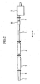
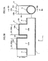
- Figures 2, 3A, and 3B show an exhaust system according to a first embodiment of the present invention, in which Fig. 2 is a general view schematically showing the exhaust system, Fig. 3A is a front view showing an exhaust chamber of the exhaust system, and Fig. 3B is a sectional view taken along a line IIIB-IIIB of Fig. 3A.
- Fig. 2 parts corresponding to those of Fig. 1 are represented with like reference numerals.
- the exhaust chamber 10 according to the first embodiment of the present invention is arranged in a rear part (close to a rear muffler 5) of an exhaust tube 1.
- the exhaust tube 1 is a tubular member connecting a premuffler 4 to the rear muftler 5 in the exhaust system.
- the exhaust chamber 10 has noise reducers 12A and 12B protruding from an outer circumferential face 1a of the exhaust tube (tubular member) 1.
- the heights of the noise reducers 12A and 12B from the outer circumferential face 1a are different from each other by a predetermined value.
- the noise reducers 12A and 12B are resonators having closed top end faces 12Aa and 12Ba and open ends 12Ab and 12Bb, respectively.
- the number of the noise reducers is, for example, two with the distances from the outer circumferential face 1a to the top faces 12Aa and 12Ba of the noise reducers 12A and 12B being different from each other by a predetermined value.
- the difference between the protruding heights of the noise reducers 12A and 12B and the cross-sectional areas (orthogonal to an axis x) of the noise reducers 12A and 12B are important factors according to the present invention.
- the positions of the protrusions of the noise reducers 12A and 12B may be anywhere on the exhaust tube 1 except on the same circumference line around the exhaust tube 1. As will easily be understood, it is preferable to protrude the noise reducers 12A and 12B in the same direction to make the exhaust chamber 10 compact.
- the exhaust chamber 10 with such a structure is shaped to reduce frequency levels that generate noise from the exhaust chamber 10 itself.
- the exhaust chamber 10 is manufacturable by forming two sheet materials into proper shapes by, for example, pressing and by joining the shaped materials together by, for example, butt welding or caulking.
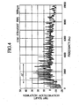
- Figure 4 shows a relationship between muffler vibration acceleration levels and noise frequencies
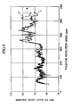
- Fig. 5 shows a relationship between noise levels and noise frequencies.
- particularly problematic noise components are high-frequency components in the range of 500 Hz to 3000 Hz (as depicted by ⁇ f). The noise levels of these high-frequency components are particularly high.
- FIG. 6 shows an example of measurement of the dependence of a linear attenuation frequency on the longitudinal lengths of the noise reducers 12A and 12B (hereinafter referred to as noise reducer lengths).
- noise reducer lengths frequencies that cause noise in the range of 500 Hz to 3000 Hz.
- frequency levels that cause noise in the range of 500 Hz to 3000 Hz can be reduced by setting the protrusion heights (shortest distances from the outer circumferential face 1a of the exhaust tube 1 to the top faces 12Aa and 12Ba) of the noise reducers 12A and 12B to values in the range of about 30 mm to 150 mm.
- the exhaust chamber 10 makes compression waves in a predetermined frequency band resonate or interfere with one another to expedite the dissipation of acoustic energy of the compression waves and attenuate the vibration components thereof.
- the exhaust system has resonant elements that have the frequency characteristic (first frequency band) of Figs. 4 and 5 to attenuate acoustic energy.
- the exhaust chamber 10 according to the embodiment is a resonator set configured to provide a frequency characteristic (second frequency band) that is different from the frequency characteristic of the exhaust system itself. Accordingly, when added to the exhaust system, the exhaust chamber 10 of the embodiment serves as an acoustic damper to modulate and correct the frequency characteristic of the exhaust system itself.
- Figure 7 shows the attenuation characteristics of the noise reducers 12A and 12B provided with cylindrical shapes having three different diameters. Changing the diameters of the noise reducers changes a frequency range to be attenuated by resonance.
- the noise reducers 12A and 12B have the closed ends 12Aa and 12Ba and open ends 12Ab and 12Bb, respectively, to serve as a resonator or an acoustic damper capable of selecting the center frequency and frequency band width of compression waves to attenuate.
- the noise reducers 12A and 12B have cylindrical shapes.
- the exhaust chamber 10 was arranged in the exhaust tube 1 between the premuffler 4 and the rear muffler 5 alternatively at a front location (close to the premuffler 4), a middle location, and a rear location (close to the rear muffler 5).
- Fig. 8 shows the dependence of noise levels on pulsator revolution speed
- Figs. 9A-9C show frequency characteristics with the pulsator being fixed at a revolution speed of 4,350 rpm.
- Figures 8 and 9A-9C show that a greater noise reduction effect is obtainable when the exhaust chamber 10 is arranged close to the rear muffler 5 and upstream from the rear muffler 5 in an exhaust flowing direction.
- the reason for this is that because the noise reducers 12A and 12B of the exhaust chamber 10 define acoustic boundaries, arranging the exhaust chamber 10 at the front part of the exhaust tube 1 increases the influence of resonance between the exhaust chamber 10 and the rear muffler 5.
- the frequency analysis results as shown in Figs. 8 and 9 show that the noise contains more high-frequency components of 8kHz or below as the exhaust chamber 10 to the front part of the exhaust tube 1 is arranged closer.
- Figure 10 shows relationships between emitted noise levels and pulsator revolution speeds with and without the exhaust chamber 10, to clarify the effect of the exhaust chamber 10. It is apparent from Fig. 10 that the effect of the exhaust chamber 10 becomes conspicuous as the revolution speed of the pulsator increases thus increasing high-frequency components and that the effect of the exhaust chamber 10 corresponds to 10 dB or more.
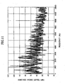
- Figure 11 shows the effect of the exhaust chamber 10 attached to an exhaust system on the reduction of frequency components in emitted noise.
- the effect is conspicuous, in particular, in the range of 500 Hz to 3000 Hz. It is understood that the exhaust chamber 10 is applicable to any exhaust system to reduce emitted noise.
- the exhaust chamber 10 has a simple structure involving the noise reducers 12A and 12B projected from the outer circumferential face 1a of the exhaust tube 1 by different protrusion heights. Due to this simple structure, the exhaust chamber 10 has layout flexibility and is economical in cost. Exhaust from an engine is passed through the exhaust tube 1 and is guided into the noise reducers 12A and 12B of the exhaust chamber 10, which successively attenuate compression waves of the exhaust having noise generating frequencies of 500 Hz to 3000 Hz through resonance or interference. In this way, the exhaust chamber 10 can effectively reduce the intensity of pulsating waves of exhaust discharged into the rear muffler 5.
- the exhaust chamber 10 Since the exhaust chamber 10 is arranged upstream (closer to the engine) from the rear muffler 5 in the exhaust system, high-frequency noise remaining in the exhaust discharged into the rear muffler 5 can be muffled in the rear muffler 5, and the silenced exhaust is discharged to the outside.
- the exhaust chamber 10 When applied to an exhaust system, the exhaust chamber 10 according to the present invention can reduce frequency levels that cause noise. Accordingly, the exhaust chamber 10 helps standardize the design of the rear muffler 5, to greatly reduce the cost of the exhaust system.
- the first embodiment forms the exhaust chamber 10 by protruding the noise reducers 12A and 12B from the exhaust tube 1.
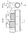
- the noise reducers 12A and 12B of the exhaust chamber 10 may be filled with noise absorbing material K such as glass wool, rock wool, or urethane (if low temperature is expected) to efficiently absorb the energy of compression waves.
- a scatter preventive mesh 21 may be provided for an entrance (substantially in the same plane as an inner wall face of the exhaust tube 1) of each of the noise reducers 12A and 12B. In this case, the noise absorbing material K further improves the noise reducing effect.
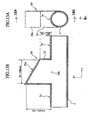
- Figures 13A and 13B show an exhaust chamber according to the second embodiment of the present invention, in which Fig. 13A is a front view showing the exhaust chamber and Fig. 13B is a sectional view taken along a line XIIIB-XIIIB of Fig. 13A.
- the exhaust chamber 30 is basically the same as the exhaust chamber 10 of the first embodiment except that the exhaust chamber 30 has a noise reducer 31 of different shape and the number of noise reducers is different from that of the first embodiment.
- the noise reducer 31 of the exhaust chamber 30 has different protrusion heights between front and rear parts thereof along the length (z-axis) of an exhaust tube 1.
- the protrusion heights are measured in a direction (x-axis direction) intersecting the principal direction (z-axis) of the exhaust tube 1, and distributes from about 30 mm to 150 mm according to the second embodiment. Due to the different protrusion heights, a closed top end face 31a of the noise reducer 31 inclines.
- the exhaust chamber 30 is arranged in the exhaust tube 1 close to a rear muffler 5 in an exhaust system. Exhaust generated in an engine is passed through the exhaust tube 1 and is guided into the noise reducer 31 before the rear muffler 5, and the noise reducer 31 successively attenuates, through resonance, frequency levels that are caused by pulsation of the exhaust and may cause noise. Since the top face 31a of the noise reducer 31 is inclined by a predetermined value, the noise reducer 31 with a limited volume can attenuate a wide range of high-frequency levels and reduce a wide range of pulsation levels of the exhaust to be discharged into the rear muffler 5.
- the exhaust chamber 30 is an acoustic damper serving as a resonator having the closed end 31a and an open end 31b capable of selecting a frequency band width of compression waves to damp from a wider range.
- the number of slopes on the top face 31a is not limited to one. Namely, the top face 31a may include a plurality of slopes or curved faces.
- the exhaust chamber 30 is formed in the exhaust tube 1 with the noise reducer 31 protruding from the exhaust tube 1 and the top face 31a inclining by a predetermined value.
- the noise reducer 31 may be filled with noise absorbing material such as glass wool.
- a scatter preventive mesh may be arranged at an entrance (substantially in the same plane as an inner wall face of the exhaust tube 1) of the noise reducer 31. In this case, the noise absorbing material improves the dispersion of compression wave energy and further increases the effect of reducing high-frequency components.
- Figure 14 is a sectional view showing an exhaust chamber according to the third embodiment of the present invention.
- the exhaust chamber 40 of Fig. 14 is basically the same as the exhaust chamber 10 of the first embodiment except that the exhaust chamber 40 has noise reducers 41A and 41B of different shapes and different locations from the noise reducers of the first embodiment.
- a pair of openings 1b and 1c are formed on an outer circumferential face 1a of an exhaust tube 1 and the noise reducer 41A is arranged to connect the openings 1b and 1c to each other.
- Another pair of openings 1d and 1e are formed on the outer circumferential face 1a and the noise reducer 41B is arranged to connect the openings 1d and 1e to each other.
- the noise reducer 41A has the open ends 1b and 1c open to an inner circumferential face of the exhaust tube 1
- the noise reducer 41B has the open ends 1d and 1e open to the inner circumferential face of the exhaust tube 1.
- a distance between the openings 1b and 1c of the noise reducer 41A and a distance between the openings 1d and 1e of the noise reducer 41B may be changed in a predetermined range (about 50 mm to 200 mm in this embodiment) depending on a peak level of emitted noise caused by exhaust.
- the total length of each of the noise reducers 41A and 41B can be changed in a predetermined range (about 150 mm to 300 mm in this embodiment).
- the noise reducer 41A and a part 41C of the exhaust tube 1 between the openings 1b and 1c form a resonator.
- a path length L1 of the noise reducer 41A for compression waves, a path length L0 of the exhaust tube part 41C for compression waves, and the difference of path length L1-L0 determine a peak level of emitted noise.
- the noise reducer 41B is also configured in the same way,
- the exhaust chamber 40 of the third embodiment expedites the dispersion of energy of compression waves in a given frequency band through resonance or interference, thereby attenuating the vibration components of the compression waves.
- the noise reducer 41A has the two open ends 1b and 1c and the noise reducer 41B has the two open ends 1d and 1e, to form an acoustic damper serving as a resonator capable of selecting the center frequency and frequency band width of compression waves to attenuate.
- each of the noise reducers 41A and 41B is an important factor when designing the noise reducers 41A and 41B, as explained in connection with the first embodiment.
- the openings 1b and 1d to be arranged on the upstream side among the openings 1b, 1c, 1d, and 1e must be distanced at least by 50 mm from each other.
- the noise reducers 41A and 41B may be positioned anywhere in the exhaust tube 1. It is preferable to arrange the noise reducers 41A and 41B in the same plane to make the exhaust chamber 10 compact.
- the openings 1b, 1c, 1d, and 1e and the noise reducers 41A and 41B are each circular. This does not limit the present invention.
- the shapes of the openings 1b, 1c, 1d, and 1e and the noise reducers 41A and 41B may be rectangular to provide the same effect as the circular ones if the equivalent diameter of the rectangular one is equal to the diameter of the circular one.
- the exhaust chamber 40 has a simple structure with at least two pairs of openings 1b, 1c, 1d, and 1e being formed on the outer circumferential face 1a of the exhaust tube 1 and being connected to each other through the noise reducers 41A and 41B.
- the exhaust chamber 40 therefore, has layout flexibility and is economical in cost.
- exhaust from an engine is passed through the exhaust tube 1 and is guided into the noise reducers 41A and 41B of the exhaust chamber 40 before a rear muffler 5.
- the exhaust chamber 40 causes interference in high-frequency components produced by pulsation of the exhaust.
- the exhaust chamber 40 of simple structure attenuates the levels of high-frequency components of the exhaust that cause noise. Namely, the exhaust chamber 40 can effectively reduce a wide range of pulsation levels of the exhaust discharged into the rear muffler 5.
- the exhaust chamber 40 is arranged upstream (on the engine side) from the rear muffler 5 in the exhaust system, high-frequency noise remaining in the exhaust discharged into the rear muffler 5 can be muffled by the rear muffler 5, and the silenced exhaust can be discharged to the outside.
- the exhaust chamber 40 can reduce emitted noise by application to an exhaust system. Accordingly, the exhaust chamber 40 helps standardize the design of a rear muffler, to greatly reduce the cost of the exhaust system.
- the exhaust chamber 40 is constituted by forming two pairs of the openings 1b, 1c, 1d, and 1e on the outer circumferential face 1a of the exhaust tube 1 and by connecting these openings to each other with the noise reducers 41A and 41B.
- This configuration does not limit the present invention.
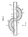
- an exhaust chamber 50 shown in Fig. 15 is possible.
- parts corresponding to those of Fig. 14 are represented with like reference numerals.
- the exhaust chamber 50 has noise reducers 41A and 41B filled with noise absorbing material K such as glass wool, rock wool, or urethane (if low temperature is expected).
- a scatter preventive mesh 51 can be arranged at each of the openings 1b, 1c, 1d, and 1e of the noise reducers 41A and 41B.
- the noise absorbing material K can further improve the emitted noise reducing effect.
- the exhaust chambers 10, 20,30,40, and 50 are each constructed by forming two sheet materials into proper shapes by pressing, abutting the two formed sheet materials against each other, and joining them together by, for example, welding or caulking.
- the exhaust chambers may be formed at lower cost by hydroforming.
- Figures 16, 17A, and 17B show an exhaust system according to the fourth embodiment of the present invention, in which Fig. 16 is a general view schematically showing the exhaust system and Figs. 17A and 17B are partly broken front and top sectional views showing a rear muffler incorporating an exhaust chamber according to the fourth embodiment.
- the structure of the exhaust chamber 60 of this embodiment is the same as the exhaust chamber 10 of the first embodiment, and therefore, the same parts as those of the first embodiment will not be explained in detail.
- the exhaust chamber 60 is arranged to also serve as a front end plate 61 in the rear muffler 55 in the exhaust system.
- the exhaust chamber 60 has a first end being open to an insertion tube 63A that is a part of an exhaust tube 1 to guide exhaust into the rear muffler 55.
- a second end of the exhaust chamber 60 is closed.
- the exhaust chamber 60 consists of a plurality of noise reducers 62A and 62B having different protrusion heights from the exhaust tube 1, i.e., different distances between the first and second ends of the exhaust chamber 60. The difference between the heights of the noise reducers 62A and 62B is predetermined.
- the noise reducers 62A and 62B have top faces 62Aa and 62Ba, respectively, corresponding to the second end of the exhaust chamber 60.
- the top faces 62Aa and 62Ba may substantially be parallel with the exhaust tube 1. In this case, the distances from the exhaust tube 1 to the top faces 62Aa and 62Ba of the noise reducers 62A and 62B, i.e., the projection heights of the noise reducers 62A and 62B differ from each other by a predetermined value.
- the insertion tube 63A has a first end that forms substantially a right angle to the exhaust tube 1 and communicates therewith and a second end that forms substantially a right angle to a partition wall 64 in the rear muffler 55 and is extended thereto.
- the difference between the projection heights of the noise reducers 62A and 62B and the cross-sectional areas of the noise reducers 62A and 62B are important factors of the fourth embodiment, like the first embodiment.
- the insertion tube 63A from which the exhaust chamber 60 protrudes guides exhaust to the downstream side thereof.
- the exhaust is discharged from the insertion tube 63A into a downstream chamber of the rear muffler 55 partitioned with the partition wall 64 having, for example, a mesh structure. Thereafter, the exhaust is guided into an exhaust tube 63B from which to the atmosphere. At this time, part of the exhaust passes through air holes 63a of the insertion tube 63A, air holes 63b of the exhaust tube 63B, and the partition wall 64. This results in canceling high-frequency noise caused by the exhaust.
- the exhaust chamber 60 as the acoustic dumper is arranged at an exhaust upstream side in the rear muffler 55 of the exhaust system. Accordingly, even if the exhaust discharged from the insertion tube 63A contains little high-frequency noise, the noise can be silenced when the exhaust passes through the air holes 63a of the insertion tube 63A, the air holes 63b of the exhaust tube 63B, and the partition wall 64. Thereafter, the noise silenced exhaust is discharged into the atmosphere.
- the exhaust chamber 60 can reduce noise-causing frequency levels and help standardize the rear muffler 55.
- the exhaust chamber 60 serves as the front end plate 61 of the rear muffler 55, to reduce noise emitted from the rear muffler 55 without increasing the number of parts. This results in greatly reducing the cost of the exhaust system.
- the exhaust chamber 60 is formed by protruding the noise reducers 62A and 62B from the insertion tube 63A communicating with the exhaust tube 1.
- the noise reducers 62A and 62B may be filled with noise absorbing material K such as glass wool, rock wool, or urethane (if low temperature is expected).
- a scatter preventive mesh M may be provided for an opening (substantially in the same plane as an inner wall face of the insertion tube 63A) of each of the noise reducers 62A and 62B. In this case, the noise absorbing material K further improves the noise reducing effect.
- Figures 19A and 19B show an exhaust chamber 70 according to a first modification of the fourth embodiment of the present invention.
- the exhaust chamber 70 of Figs. 19A and 19B is basically the same as the exhaust chamber 60 of Figs. 18A and 18B except that the exhaust chamber 70 has a noise reducer 71 of different shape and that the number of protruding noise reducers is different.
- a resonator structure of the exhaust chamber 70 is the same as that of the exhaust chamber 30 of the second embodiment, and therefore, detailed explanation thereof will be omitted.
- the exhaust chamber 70 is formed on an insertion tube 63A communicating with an exhaust tube 1.
- the noise reducer 71 of the exhaust chamber 70 protrudes from the insertion tube 63A and has a top face 71a inclined by a predetermined quantity.
- the noise reducer 71 may be filled with noise absorbing material K such as glass wool, rock wool, or urethane (if low temperature is expected).
- a scatter preventive mesh M may be provided for an opening (substantially in the same plane as an inner wall face of the insertion tube 63A) of the noise reducer 71. In this case, the noise absorbing material K further improves the noise reducing effect.
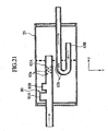
- Figure 21 shows an exhaust chamber 80 according to a second modification of the fourth embodiment of the present invention.
- the exhaust chamber 80 is basically the same as the exhaust chamber 60 of Figs. 17A and 17B except that the second modification employs an insertion tube 63A of different shape from which noise reducers 81 A and 81B of the exhaust chamber 80 protrude.
- the structure of the exhaust chamber 80 is the same as the exhaust chamber 10 of the first embodiment, and therefore, the detailed explanation thereof will be omitted.
- the insertion tube 63A from which the noise reducers 81A and 81B of the exhaust chamber 80 protrude has a first end substantially linearly communicating with an exhaust tube 1 and a second end substantially linearly extending to a partition wall 64 in a rear muffler 55.
- the exhaust chamber 80 is formed at an exhaust upstream side in the rear muffler 55 of the exhaust system. Exhaust generated in an engine or a compressor is passed through the exhaust tube 1 and guided into the rear muffler 55. At this time, the exhaust is guided into the noise reducers 81A and 81B of the exhaust chamber 80, to successively attenuate, through resonance, a frequency range of about 500 Hz to 3000 Hz of the exhaust that may cause noise. This effectively reduces pulsation levels of the noise discharged into an exhaust tube 63B.
- the exhaust chamber 80 is formed on the insertion tube 63A communicating with the exhaust tube 1 with the noise reducers 81A and 81B of the exhaust chamber 80 protruding from the insertion tube 63A.
- the noise reducers 81A and 81B may be filled with noise absorbing material K such as glass wool, rock wool, or methane (if low temperature is expected).
- a scatter preventive mesh M may be provided for an opening (substantially in the same plane as an inner wall face of the insertion tube 63A) of each of the noise reducers 81A and 81B. In this case, the noise absorbing material K further improves the noise reducing effect.
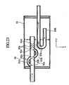
- Figure 23 shows an exhaust chamber 90 according to a third modification of the fourth embodiment of the present invention.
- the exhaust chamber 90 is basically the same as the exhaust chamber 70 of Fig. 22 except that the exhaust chamber 90 has noise reducers 91A and 91B of shapes different from those of Fig. 22.
- a resonator structure of the exhaust chamber 90 is the same as that of the exhaust chamber 40 of the third embodiment, and therefore, the explanation thereof will not be repeated.
- the exhaust chamber 90 is formed by forming two pairs of openings 92a, 92b, 92c, and 92d in an insertion tube 63A and connecting the openings 92a and 92b to each other through the noise reducer 91A, and the openings 92c and 92d to each other through the noise reducer 91B.
- a distance between the openings 92a and 92b of the noise reducer 91A and a distance between the openings 92c and 92d of the noise reducer 91B are changed in a predetermined range (about 50 mm to 200 mm according to this medication) depending on a peak level of emitted noise caused by exhaust.
- the total length of each of the noise reducers 91A and 91B is changed in a predetennined range (about 150 mm to 300 mm according to this modification).
- each of the noise reducers 91A and 91B is an important factor when designing the noise reducers 91 A and 91 B.
- the openings 92a and 92c to be arranged on the upstream side among the openings 92a, 92b, 92c, and 92d must be distanced at least by 50 mm from each other.
- the noise reducers 91A and 91B may be positioned anywhere on the insertion tube 63A.
- the openings 92a to 92d and the noise reducers 91A and 91B are each circular.
- the shapes of the openings 92a to 92d and the noise reducers 91A and 91B may be rectangular to provide the same effect as the circular ones if the equivalent diameter of the rectangular one is equal to the diameter of the circular one.
- the exhaust chamber 90 has a simple structure with the two pairs of the openings 92a, 92b, 92c, and 92d being formed in the insertion tube 63A and being connected to each other through the noise reducers 91A and 91B.
- the exhaust chamber 90 thesefore, has layout flexibility and is economical in cost.
- exhaust generated in an engine or a compressor is passed through an exhaust tube 1 and guided into a rear muffler 55.
- the exhaust is guided into the noise reducers 91A and 91B of the exhaust chamber 90, to cause interference in high-frequency components caused by pulsation of the exhaust.
- this simple structure can attenuate the levels of the high-frequency components of the exhaust that may cause noise and can effectively reduce a wide range of pulsation levels of the exhaust discharged into an exhaust tube 63B.
- the exhaust chamber 90 is arranged upstream from the rear muffler 55 in the exhaust system. Accordingly, even if the exhaust discharged from the insertion tube 63A contains little high-frequency noise, the noise can be silenced when the exhaust passes through air holes 63a of the insertion tube 63A, air holes 63b of the exhaust tube 63B, and a partition wall 64. Thereafter, the silenced exhaust is discharged into the atmosphere.
- the exhaust chamber 90 can reduce emitted noise, and therefore, can help standardize the rear muftler 55 and greatly reduce the cost of the exhaust system.
- the exhaust chamber 90 is constituted by forming the openings 92a, 92b, 92c, and 92d in the insertion tube 63A and connecting the openings 92a and 92b to each other through the noise reducer 91A and the openings 92c and 92d to each other through the noise reducer 91B.
- the noise reducers 91A and 91 B may be filled with noise absorbing material K such as glass wool, rock wool, or urethane (if low temperature is expected).
- a scatter preventive mesh M may be provided for each of the openings 92a, 92b, 92c, and 92d. In this case, the noise absorbing material K further improves the noise reducing effect.
- the exhaust chambers 60, 70, 80, and 90 according to the fourth embodiment and the modifications thereof are each formed by forming two sheet materials into proper shapes by pressing, abutting the two formed sheet materials against each other, and joining them together by, for example, welding or caulking.
- the exhaust chambers may be formed at lower costs by hydroforming.
Landscapes
- Engineering & Computer Science (AREA)
- Chemical & Material Sciences (AREA)
- Combustion & Propulsion (AREA)
- Mechanical Engineering (AREA)
- General Engineering & Computer Science (AREA)
- Physics & Mathematics (AREA)
- Acoustics & Sound (AREA)
- Multimedia (AREA)
- Exhaust Silencers (AREA)
Abstract
Description
- The present invention relates to an exhaust system to discharge exhaust produced in an engine of, for example, a vehicle or a compressor to the atmosphere and reduce noise caused by the exhaust
- Figure 1 shows an example of an exhaust system. The exhaust system includes
exhaust tubes 1, acast exhaust manifold 2 to collect exhaust from cylinders of an engine and send the collected exhaust to an adjacent one of theexhaust tubes 1, acatalytic converter 3 to convert a toxic substance such as CO, HC, and NOX contained in the exhaust into a harmless substance such as CO2, H2O, and NO2 through catalytic reaction, and apremuffler 4 andrear muffler 5 to muffle noise caused by the exhaust. Thesecomponents exhaust tubes 1. - A
flexible tube 6 is arranged between theexhaust tube 1 connected to thecast exhaust manifold 2 and theexhaust tube 1 connected to thecatalytic converter 3, to flexibly connect themanifold 2 and converter 3 to each other. - In recent years, exhaust systems have tended to increase the diameters of exhaust tubes to reduce back pressure, or increase the volumes of premufflers and rear mufflers to improve a muffling effect. This tendency has resulted in increasing the cross-sectional areas of the mufflers.
- Increasing the diameters of the
exhaust tubes 1 may decrease a pressure loss and hardly attenuate pulsating pressure produced from the engine. The pulsating pressure sometimes changes into shock wave. Namely, the pulsation easily results in emitting noise from a part of the exhaust system. - Enlarging the
premuffler 4 andrear muffler 5 to increase muffling effect must encounter limits related to a vehicle layout. To avoid the limits, themufflers rear muffler 5 is usually larger than thepremuffler 4, and therefore, it emits larger noise. - To reduce such noise, there are some recently disclosed techniques. For example, Japanese Unexamined Patent Application Publication No. 2002-21594 discloses a technique of changing the rigidity of a muffler to improve muffling efficiency, and Japanese Unexamined Patent Application Publication No. 9-49415 discloses a technique of filling a premuffler with noise absorbing material to improve the muffling effect of an exhaust system as a whole.
- Muffling levels achieved by the disclosure 2002-21594 are variable depending on exhaust systems, and therefore, the disclosure is inapplicable to standardizing mufflers. Namely, the disclosure must properly set the rigidity of a rear muffler for a given exhaust system, to increase the cost of the exhaust system. The disclosure involves such an unsolved problem.
- The disclosure 9-49415 uses a large quantity of noise absorbing material which increases the cost of the exhaust system. In addition, the noise absorbing material may scatter to deteriorate the muffling effect of the exhaust system and cause environmental problems. This disclosure involves such an unsolved problem.
- The noise absorbing material absorbs condensed water and sticks to the exhaust system to deteriorate the muffling effect thereof. In addition, the noise absorbing material is difficult to recycle and poses a demerit against such recent social trends. It is preferable, therefore, not to use the noise absorbing material if possible.
- To solve these problems, the present invention provides an exhaust system that is manufacturable at low cost and is capable of effectively reducing noise emission.
- A first aspect of the present invention provides an acoustic damper structure including a tubular member configured to discharge exhaust from an engine or a compressor and attenuate acoustic energy of a first frequency band and a resonator set configured to attenuate acoustic energy of a second frequency band, which is different from the first frequency band, and modulate the first frequency band.
- Based on the acoustic damper structure of the first aspect, a second aspect of the present invention provides the resonator set with at least two resonators. Each of the resonators has an open first end opening to an inner face of the tubular member and a closed second end. The resonators have different lengths.
- Based on the acoustic damper structure of the first aspect, a third aspect of the present invention provides the resonator set with at least one resonator. The resonator has an open first end opening to an inner face of the tubular member and a closed second end. The closed second end includes a plane that is not in parallel with the plane of the open first end.
- Based on the acoustic damper structure of the first aspect, a fourth aspect of the present invention provides the resonator set with at least one resonator. Each end of the resonator is open to an inner face of the tubular member.
- Based on the acoustic damper structure of any one of the first to fourth aspects, a fifth aspect of the present invention arranges the resonator set at an exhaust upstream side in a muffler connected to an end of the tubular member.
-
- Figure 1 is a general view schematically showing an exhaust system according to a related art;
- Fig. 2 is a general view schematically showing an exhaust system employing an exhaust chamber according to a first embodiment of the present invention;
- Fig. 3A is a sectional view showing the exhaust chamber according to the first embodiment;
- Fig. 3B is a sectional view taken along a line IIIB-IIIB of Fig. 3A;
- Fig. 4 is a graph showing a frequency analysis of muffler vibration acceleration;
- Fig. 5 is a graph showing a frequency analysis of emitted noise;
- Fig. 6 is a graph showing changes in linear attenuation center frequencies relative to noise reducer lengths;
- Fig. 7 is a graph showing an influence of the diameter of a noise reducer on muffling effect;
- Fig. 8 is a graph showing emitted noise characteristics relative to pulsator revolution speeds and exhaust chamber arranging positions;
- Figs. 9A-9C are graphs each showing emitted noise characteristics relative to frequencies and exhaust chamber arranging positions;
- Fig. 10 is a graph showing the emitted noise reducing effect of an exhaust chamber,
- Fig. 11 is a graph showing a relationship between emitted noise levels and frequencies;
- Fig. 12A is a view showing an exhaust chamber according to a modification of the first embodiment of the present invention;
- Fig. 12B is a sectional view taken along a line XIIB-XIIB of Fig. 12A;
- Fig. 13A is a view showing an exhaust chamber according to a second embodiment of the present invention;
- Fig. 13B is a sectional view taken along a line XIIIB-XIIIB of Fig. 13A;
- Fig. 14 is a sectional view showing an exhaust chamber according to a third embodiment of the present invention;
- Fig. 15 is a sectional view showing an exhaust chamber according to a modification of the third embodiment of the present invention;
- Fig. 16 is a general view schematically showing an exhaust system employing an exhaust chamber according to a fourth embodiment of the present invention;
- Fig. 17A is a view showing the exhaust chamber according to the fourth embodiment of the present invention;
- Fig. 17B is a sectional view taken along a line XVIIB-XVIIB of Fig. 17A;
- Fig. 18A is a view showing an exhaust chamber according to an alteration of the fourth embodiment of the present invention;
- Fig. 18B is a sectional view taken along a line XVIIIB-XVIIIB of Fig. 18A;
- Fig. 19A is a view showing an exhaust chamber according to a first modification of the fourth embodiment of the present invention;
- Fig. 19B is a sectional view taken along a line XIXB-XIXB of Fig. 19A;
- Fig. 20A is a view showing an exhaust chamber according to an alteration of the first modification of the fourth embodiment of the present invention;
- Fig. 20B is a sectional view taken along a line XXB-XXB of Fig. 20A;
- Fig. 21 is a view showing an exhaust chamber according to a second modification of the fourth embodiment of the present invention;
- Fig. 22 is a view showing an exhaust chamber according to an alteration of the second modification of the fourth embodiment of the present invention;
- Fig. 23 is a view showing an exhaust chamber according to a third modification of the fourth embodiment of the present invention; and
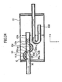
- Fig. 24 is a view showing an exhaust chamber according to an alteration of the third modification of the fourth embodiment of the present invention.
-
- Various embodiments of the present invention will be described in detail with reference to the accompanying drawings.
- Figures 2, 3A, and 3B show an exhaust system according to a first embodiment of the present invention, in which Fig. 2 is a general view schematically showing the exhaust system, Fig. 3A is a front view showing an exhaust chamber of the exhaust system, and Fig. 3B is a sectional view taken along a line IIIB-IIIB of Fig. 3A. In Fig. 2, parts corresponding to those of Fig. 1 are represented with like reference numerals. In Fig. 2, the
exhaust chamber 10 according to the first embodiment of the present invention is arranged in a rear part (close to a rear muffler 5) of anexhaust tube 1. Theexhaust tube 1 is a tubular member connecting apremuffler 4 to therear muftler 5 in the exhaust system. - In Figs. 3A and 3B, the
exhaust chamber 10 hasnoise reducers noise reducers - In a case where the top faces 12Aa and 12Ba of the
noise reducers exhaust tube 1, the number of the noise reducers is, for example, two with the distances from the outer circumferential face 1a to the top faces 12Aa and 12Ba of thenoise reducers noise reducers noise reducers noise reducers exhaust tube 1 except on the same circumference line around theexhaust tube 1. As will easily be understood, it is preferable to protrude thenoise reducers exhaust chamber 10 compact. - The
exhaust chamber 10 with such a structure is shaped to reduce frequency levels that generate noise from theexhaust chamber 10 itself. Theexhaust chamber 10 is manufacturable by forming two sheet materials into proper shapes by, for example, pressing and by joining the shaped materials together by, for example, butt welding or caulking. - To reduce nose generated in the
rear muffler 5, a measure must be taken at a stage in front of therear muffler 5. Namely, it is necessary to suppress frequency levels passing through theexhaust tube 1 and causing noise in therear muffler 5. - Figure 4 shows a relationship between muffler vibration acceleration levels and noise frequencies, and Fig. 5 shows a relationship between noise levels and noise frequencies. As is apparent in Figs. 4 and 5, particularly problematic noise components are high-frequency components in the range of 500 Hz to 3000 Hz (as depicted by Δf). The noise levels of these high-frequency components are particularly high.
- This tendency more or less appears in substantially every exhaust system, and therefore, the present inventors have paid attention to noise consisting of the frequency components in the range of 500 Hz to 3000 Hz. The inventors considered that noise emitted from a rear muffler of substantially any exhaust system is suppressible by providing an exhaust system with a resonator structure having a resonance characteristic that is different from the resonance characteristic of the exhaust system itself.
- The present inventors have employed a linear attenuation center frequency as an index representative of a level reducing characteristic. Figure 6 shows an example of measurement of the dependence of a linear attenuation frequency on the longitudinal lengths of the
noise reducers exhaust tube 1 to the top faces 12Aa and 12Ba) of thenoise reducers - The
exhaust chamber 10 according to the embodiment of the present invention makes compression waves in a predetermined frequency band resonate or interfere with one another to expedite the dissipation of acoustic energy of the compression waves and attenuate the vibration components thereof. The exhaust system has resonant elements that have the frequency characteristic (first frequency band) of Figs. 4 and 5 to attenuate acoustic energy. Theexhaust chamber 10 according to the embodiment is a resonator set configured to provide a frequency characteristic (second frequency band) that is different from the frequency characteristic of the exhaust system itself. Accordingly, when added to the exhaust system, theexhaust chamber 10 of the embodiment serves as an acoustic damper to modulate and correct the frequency characteristic of the exhaust system itself. - Figure 7 shows the attenuation characteristics of the
noise reducers noise reducers - According to this embodiment, the
noise reducers noise reducers - Detected results of the noise emission characteristics of exhaust systems each employing the
exhaust chamber 10 according to the embodiment of the present invention will be explained. - In the exhaust systems, the
exhaust chamber 10 was arranged in theexhaust tube 1 between thepremuffler 4 and therear muffler 5 alternatively at a front location (close to the premuffler 4), a middle location, and a rear location (close to the rear muffler 5). With these three arrangements of theexhaust chamber 10, Fig. 8 shows the dependence of noise levels on pulsator revolution speed and Figs. 9A-9C show frequency characteristics with the pulsator being fixed at a revolution speed of 4,350 rpm. - Figures 8 and 9A-9C show that a greater noise reduction effect is obtainable when the
exhaust chamber 10 is arranged close to therear muffler 5 and upstream from therear muffler 5 in an exhaust flowing direction. The reason for this is that because thenoise reducers exhaust chamber 10 define acoustic boundaries, arranging theexhaust chamber 10 at the front part of theexhaust tube 1 increases the influence of resonance between theexhaust chamber 10 and therear muffler 5. The frequency analysis results as shown in Figs. 8 and 9 show that the noise contains more high-frequency components of 8kHz or below as theexhaust chamber 10 to the front part of theexhaust tube 1 is arranged closer. - Figure 10 shows relationships between emitted noise levels and pulsator revolution speeds with and without the
exhaust chamber 10, to clarify the effect of theexhaust chamber 10. It is apparent from Fig. 10 that the effect of theexhaust chamber 10 becomes conspicuous as the revolution speed of the pulsator increases thus increasing high-frequency components and that the effect of theexhaust chamber 10 corresponds to 10 dB or more. - Figure 11 shows the effect of the
exhaust chamber 10 attached to an exhaust system on the reduction of frequency components in emitted noise. The effect is conspicuous, in particular, in the range of 500 Hz to 3000 Hz. It is understood that theexhaust chamber 10 is applicable to any exhaust system to reduce emitted noise. - The
exhaust chamber 10 according to the present invention has a simple structure involving thenoise reducers exhaust tube 1 by different protrusion heights. Due to this simple structure, theexhaust chamber 10 has layout flexibility and is economical in cost. Exhaust from an engine is passed through theexhaust tube 1 and is guided into thenoise reducers exhaust chamber 10, which successively attenuate compression waves of the exhaust having noise generating frequencies of 500 Hz to 3000 Hz through resonance or interference. In this way, theexhaust chamber 10 can effectively reduce the intensity of pulsating waves of exhaust discharged into therear muffler 5. - Since the
exhaust chamber 10 is arranged upstream (closer to the engine) from therear muffler 5 in the exhaust system, high-frequency noise remaining in the exhaust discharged into therear muffler 5 can be muffled in therear muffler 5, and the silenced exhaust is discharged to the outside. - When applied to an exhaust system, the
exhaust chamber 10 according to the present invention can reduce frequency levels that cause noise. Accordingly, theexhaust chamber 10 helps standardize the design of therear muffler 5, to greatly reduce the cost of the exhaust system. - The first embodiment forms the
exhaust chamber 10 by protruding thenoise reducers exhaust tube 1. The present invention is not limited to the embodiments described above. For example, as shown in Figs. 12A and 12B, thenoise reducers exhaust chamber 10 may be filled with noise absorbing material K such as glass wool, rock wool, or urethane (if low temperature is expected) to efficiently absorb the energy of compression waves. To prevent the noise absorbing material K from scattering, a scatterpreventive mesh 21 may be provided for an entrance (substantially in the same plane as an inner wall face of the exhaust tube 1) of each of thenoise reducers - Figures 13A and 13B show an exhaust chamber according to the second embodiment of the present invention, in which Fig. 13A is a front view showing the exhaust chamber and Fig. 13B is a sectional view taken along a line XIIIB-XIIIB of Fig. 13A.
- In Figs. 13A and 13B, the
exhaust chamber 30 is basically the same as theexhaust chamber 10 of the first embodiment except that theexhaust chamber 30 has anoise reducer 31 of different shape and the number of noise reducers is different from that of the first embodiment. - The
noise reducer 31 of theexhaust chamber 30 has different protrusion heights between front and rear parts thereof along the length (z-axis) of anexhaust tube 1. The protrusion heights are measured in a direction (x-axis direction) intersecting the principal direction (z-axis) of theexhaust tube 1, and distributes from about 30 mm to 150 mm according to the second embodiment. Due to the different protrusion heights, a closedtop end face 31a of thenoise reducer 31 inclines. - The
exhaust chamber 30 is arranged in theexhaust tube 1 close to arear muffler 5 in an exhaust system. Exhaust generated in an engine is passed through theexhaust tube 1 and is guided into thenoise reducer 31 before therear muffler 5, and thenoise reducer 31 successively attenuates, through resonance, frequency levels that are caused by pulsation of the exhaust and may cause noise. Since thetop face 31a of thenoise reducer 31 is inclined by a predetermined value, thenoise reducer 31 with a limited volume can attenuate a wide range of high-frequency levels and reduce a wide range of pulsation levels of the exhaust to be discharged into therear muffler 5. Theexhaust chamber 30 according to this embodiment is an acoustic damper serving as a resonator having theclosed end 31a and anopen end 31b capable of selecting a frequency band width of compression waves to damp from a wider range. The number of slopes on thetop face 31a is not limited to one. Namely, thetop face 31a may include a plurality of slopes or curved faces. - According to the second embodiment, the
exhaust chamber 30 is formed in theexhaust tube 1 with thenoise reducer 31 protruding from theexhaust tube 1 and thetop face 31a inclining by a predetermined value. This arrangement does not limit the present invention. For example, thenoise reducer 31 may be filled with noise absorbing material such as glass wool. To prevent the noise absorbing material from scattering, a scatter preventive mesh may be arranged at an entrance (substantially in the same plane as an inner wall face of the exhaust tube 1) of thenoise reducer 31. In this case, the noise absorbing material improves the dispersion of compression wave energy and further increases the effect of reducing high-frequency components. - Figure 14 is a sectional view showing an exhaust chamber according to the third embodiment of the present invention. The
exhaust chamber 40 of Fig. 14 is basically the same as theexhaust chamber 10 of the first embodiment except that theexhaust chamber 40 hasnoise reducers - A pair of
openings exhaust tube 1 and thenoise reducer 41A is arranged to connect theopenings openings 1d and 1e are formed on the outer circumferential face 1a and thenoise reducer 41B is arranged to connect theopenings 1d and 1e to each other. Namely, thenoise reducer 41A has the open ends 1b and 1c open to an inner circumferential face of theexhaust tube 1, and thenoise reducer 41B has the open ends 1d and 1e open to the inner circumferential face of theexhaust tube 1. - A distance between the
openings noise reducer 41A and a distance between theopenings 1d and 1e of thenoise reducer 41B may be changed in a predetermined range (about 50 mm to 200 mm in this embodiment) depending on a peak level of emitted noise caused by exhaust. At the same time, the total length of each of thenoise reducers noise reducer 41A and apart 41C of theexhaust tube 1 between theopenings noise reducer 41A for compression waves, a path length L0 of theexhaust tube part 41C for compression waves, and the difference of path length L1-L0 determine a peak level of emitted noise. Thenoise reducer 41B is also configured in the same way, - The
exhaust chamber 40 of the third embodiment expedites the dispersion of energy of compression waves in a given frequency band through resonance or interference, thereby attenuating the vibration components of the compression waves. Thenoise reducer 41A has the twoopen ends noise reducer 41B has the twoopen ends 1d and 1e, to form an acoustic damper serving as a resonator capable of selecting the center frequency and frequency band width of compression waves to attenuate. - The cross-sectional area of each of the
noise reducers noise reducers openings openings noise reducers exhaust tube 1. It is preferable to arrange thenoise reducers exhaust chamber 10 compact. - According to the third embodiment, the
openings noise reducers openings noise reducers - The
exhaust chamber 40 has a simple structure with at least two pairs ofopenings exhaust tube 1 and being connected to each other through thenoise reducers exhaust chamber 40, therefore, has layout flexibility and is economical in cost. In the exhaust system, exhaust from an engine is passed through theexhaust tube 1 and is guided into thenoise reducers exhaust chamber 40 before arear muffler 5. Theexhaust chamber 40 causes interference in high-frequency components produced by pulsation of the exhaust. As a result, theexhaust chamber 40 of simple structure attenuates the levels of high-frequency components of the exhaust that cause noise. Namely, theexhaust chamber 40 can effectively reduce a wide range of pulsation levels of the exhaust discharged into therear muffler 5. - Since the
exhaust chamber 40 is arranged upstream (on the engine side) from therear muffler 5 in the exhaust system, high-frequency noise remaining in the exhaust discharged into therear muffler 5 can be muffled by therear muffler 5, and the silenced exhaust can be discharged to the outside. - The
exhaust chamber 40 can reduce emitted noise by application to an exhaust system. Accordingly, theexhaust chamber 40 helps standardize the design of a rear muffler, to greatly reduce the cost of the exhaust system. - According to the third embodiment, the
exhaust chamber 40 is constituted by forming two pairs of theopenings exhaust tube 1 and by connecting these openings to each other with thenoise reducers exhaust chamber 50 shown in Fig. 15 is possible. In Fig 15, parts corresponding to those of Fig. 14 are represented with like reference numerals. Theexhaust chamber 50 hasnoise reducers preventive mesh 51 can be arranged at each of theopenings noise reducers - The exhaust chambers according to the first to third embodiments of the present invention have been explained. The present invention is not limited to these embodiments. Other various embodiments will be possible without departing from the spirit and scope of the present invention.
- According to the embodiments, the
exhaust chambers - Figures 16, 17A, and 17B, show an exhaust system according to the fourth embodiment of the present invention, in which Fig. 16 is a general view schematically showing the exhaust system and Figs. 17A and 17B are partly broken front and top sectional views showing a rear muffler incorporating an exhaust chamber according to the fourth embodiment. The structure of the
exhaust chamber 60 of this embodiment is the same as theexhaust chamber 10 of the first embodiment, and therefore, the same parts as those of the first embodiment will not be explained in detail. - In Fig. 16, the
exhaust chamber 60 according to this embodiment is arranged to also serve as afront end plate 61 in therear muffler 55 in the exhaust system. In Figs. 17A and 17B, theexhaust chamber 60 has a first end being open to aninsertion tube 63A that is a part of anexhaust tube 1 to guide exhaust into therear muffler 55. A second end of theexhaust chamber 60 is closed. Theexhaust chamber 60 consists of a plurality ofnoise reducers exhaust tube 1, i.e., different distances between the first and second ends of theexhaust chamber 60. The difference between the heights of thenoise reducers insertion tube 63A serving as thefront end plate 61 communicates with theexhaust tube 1 through anopening 55A of therear muffler 55. The noise reducers 62A and 62B have top faces 62Aa and 62Ba, respectively, corresponding to the second end of theexhaust chamber 60. The top faces 62Aa and 62Ba may substantially be parallel with theexhaust tube 1. In this case, the distances from theexhaust tube 1 to the top faces 62Aa and 62Ba of thenoise reducers noise reducers - The
insertion tube 63A has a first end that forms substantially a right angle to theexhaust tube 1 and communicates therewith and a second end that forms substantially a right angle to apartition wall 64 in therear muffler 55 and is extended thereto. - The difference between the projection heights of the
noise reducers noise reducers - The
insertion tube 63A from which theexhaust chamber 60 protrudes guides exhaust to the downstream side thereof. The exhaust is discharged from theinsertion tube 63A into a downstream chamber of therear muffler 55 partitioned with thepartition wall 64 having, for example, a mesh structure. Thereafter, the exhaust is guided into anexhaust tube 63B from which to the atmosphere. At this time, part of the exhaust passes throughair holes 63a of theinsertion tube 63A,air holes 63b of theexhaust tube 63B, and thepartition wall 64. This results in canceling high-frequency noise caused by the exhaust. - The
exhaust chamber 60 as the acoustic dumper is arranged at an exhaust upstream side in therear muffler 55 of the exhaust system. Accordingly, even if the exhaust discharged from theinsertion tube 63A contains little high-frequency noise, the noise can be silenced when the exhaust passes through theair holes 63a of theinsertion tube 63A, theair holes 63b of theexhaust tube 63B, and thepartition wall 64. Thereafter, the noise silenced exhaust is discharged into the atmosphere. - In the exhaust system, the
exhaust chamber 60 according to the fourth embodiment can reduce noise-causing frequency levels and help standardize therear muffler 55. In addition, theexhaust chamber 60 serves as thefront end plate 61 of therear muffler 55, to reduce noise emitted from therear muffler 55 without increasing the number of parts. This results in greatly reducing the cost of the exhaust system. - According to the fourth embodiment, the
exhaust chamber 60 is formed by protruding thenoise reducers insertion tube 63A communicating with theexhaust tube 1. This does not limit the present invention. For example, as shown in Fig. 18, thenoise reducers insertion tube 63A) of each of thenoise reducers - Figures 19A and 19B show an
exhaust chamber 70 according to a first modification of the fourth embodiment of the present invention. Theexhaust chamber 70 of Figs. 19A and 19B is basically the same as theexhaust chamber 60 of Figs. 18A and 18B except that theexhaust chamber 70 has anoise reducer 71 of different shape and that the number of protruding noise reducers is different. A resonator structure of theexhaust chamber 70 is the same as that of theexhaust chamber 30 of the second embodiment, and therefore, detailed explanation thereof will be omitted. - According to this modification, the
exhaust chamber 70 is formed on aninsertion tube 63A communicating with anexhaust tube 1. Thenoise reducer 71 of theexhaust chamber 70 protrudes from theinsertion tube 63A and has atop face 71a inclined by a predetermined quantity. This does not limit the present invention. For example, as shown in Figs. 20A and 20B, thenoise reducer 71 may be filled with noise absorbing material K such as glass wool, rock wool, or urethane (if low temperature is expected). To prevent the noise absorbing material K from scattering, a scatter preventive mesh M may be provided for an opening (substantially in the same plane as an inner wall face of theinsertion tube 63A) of thenoise reducer 71. In this case, the noise absorbing material K further improves the noise reducing effect. Second Modification - Figure 21 shows an
exhaust chamber 80 according to a second modification of the fourth embodiment of the present invention. Theexhaust chamber 80 is basically the same as theexhaust chamber 60 of Figs. 17A and 17B except that the second modification employs aninsertion tube 63A of different shape from which noise reducers 81 A and 81B of theexhaust chamber 80 protrude. The structure of theexhaust chamber 80 is the same as theexhaust chamber 10 of the first embodiment, and therefore, the detailed explanation thereof will be omitted. - The
insertion tube 63A from which the noise reducers 81A and 81B of theexhaust chamber 80 protrude has a first end substantially linearly communicating with anexhaust tube 1 and a second end substantially linearly extending to apartition wall 64 in arear muffler 55. - The
exhaust chamber 80 is formed at an exhaust upstream side in therear muffler 55 of the exhaust system. Exhaust generated in an engine or a compressor is passed through theexhaust tube 1 and guided into therear muffler 55. At this time, the exhaust is guided into the noise reducers 81A and 81B of theexhaust chamber 80, to successively attenuate, through resonance, a frequency range of about 500 Hz to 3000 Hz of the exhaust that may cause noise. This effectively reduces pulsation levels of the noise discharged into anexhaust tube 63B. - According to this modification, the
exhaust chamber 80 is formed on theinsertion tube 63A communicating with theexhaust tube 1 with the noise reducers 81A and 81B of theexhaust chamber 80 protruding from theinsertion tube 63A. This does not limit the present invention. For example, as shown in Fig. 22, the noise reducers 81A and 81B may be filled with noise absorbing material K such as glass wool, rock wool, or methane (if low temperature is expected). To prevent the noise absorbing material K from scattering, a scatter preventive mesh M may be provided for an opening (substantially in the same plane as an inner wall face of theinsertion tube 63A) of each of the noise reducers 81A and 81B. In this case, the noise absorbing material K further improves the noise reducing effect. - Figure 23 shows an
exhaust chamber 90 according to a third modification of the fourth embodiment of the present invention. Theexhaust chamber 90 is basically the same as theexhaust chamber 70 of Fig. 22 except that theexhaust chamber 90 hasnoise reducers exhaust chamber 90 is the same as that of theexhaust chamber 40 of the third embodiment, and therefore, the explanation thereof will not be repeated. - The
exhaust chamber 90 is formed by forming two pairs ofopenings insertion tube 63A and connecting theopenings noise reducer 91A, and theopenings noise reducer 91B. - A distance between the
openings noise reducer 91A and a distance between theopenings noise reducer 91B are changed in a predetermined range (about 50 mm to 200 mm according to this medication) depending on a peak level of emitted noise caused by exhaust. At the same time, the total length of each of thenoise reducers - The cross-sectional area of each of the
noise reducers noise reducers openings openings noise reducers insertion tube 63A. - According to this modification, the
openings 92a to 92d and thenoise reducers openings 92a to 92d and thenoise reducers - The
exhaust chamber 90 has a simple structure with the two pairs of theopenings insertion tube 63A and being connected to each other through thenoise reducers exhaust chamber 90, thesefore, has layout flexibility and is economical in cost. - According to the exhaust system, exhaust generated in an engine or a compressor is passed through an
exhaust tube 1 and guided into arear muffler 55. At this time, the exhaust is guided into thenoise reducers exhaust chamber 90, to cause interference in high-frequency components caused by pulsation of the exhaust. Namely, this simple structure can attenuate the levels of the high-frequency components of the exhaust that may cause noise and can effectively reduce a wide range of pulsation levels of the exhaust discharged into anexhaust tube 63B. - The
exhaust chamber 90 is arranged upstream from therear muffler 55 in the exhaust system. Accordingly, even if the exhaust discharged from theinsertion tube 63A contains little high-frequency noise, the noise can be silenced when the exhaust passes throughair holes 63a of theinsertion tube 63A,air holes 63b of theexhaust tube 63B, and apartition wall 64. Thereafter, the silenced exhaust is discharged into the atmosphere. - In the exhaust system, the
exhaust chamber 90 can reduce emitted noise, and therefore, can help standardize therear muftler 55 and greatly reduce the cost of the exhaust system. - According to this modification, the
exhaust chamber 90 is constituted by forming theopenings insertion tube 63A and connecting theopenings noise reducer 91A and theopenings noise reducer 91B. This does not limit the present invention. As shown in Fig. 24, thenoise reducers openings - Although the present invention has been explained with reference to exhaust chambers based on embodiments of the present invention, the present invention is not limited to these embodiments. Without departing from the spirit and scope of the present invention, various other embodiments are possible, and such embodiments are considered to fall in the scope of the present invention.
- For example, the
exhaust chambers
Claims (11)
- An acoustic damper for exhaust system comprising:a tubular member (1, 5, 55, 61) configured to discharge exhaust from a machine having one of an engine or a compressor and attenuate acoustic energy of a first frequency band; anda resonator set (10, 20, 30, 40, 50, 60, 70, 80, 90) configured to attenuate acoustic energy of a second frequency band, which is different from the first frequency band and modulates the first frequency band.
- The acoustic damper for exhaust system of claim 1, wherein:the resonator set (10, 20) comprises at least two resonators (12A, 12B);each of the resonators has a first end opening to an inner face of the tubular member and a closed second end; andthe resonators have different lengths.
- The acoustic damper for exhaust system of claim 1, wherein:the resonator set (30) comprises at least one resonator, andthe resonator has a first end (31b) opening to an inner face of the tubular member and a closed second end (31a) including a plane that is not in parallel with the virtual plane of the first end.
- The acoustic damper for exhaust system of claim 1, wherein:the resonator set (40, 50) comprises at least one resonator (41A, 41B); andeach end (1b, 1c, 1d, 1e) of the resonator is open to an inner face of the tubular member.
- The acoustic damper for exhaust system of any one of claims 2 to 4, wherein each of the resonators comprises noise absorbing material (K) and a scatter preventive part (21, 51).
- The acoustic damper for exhaust system of claim 1, wherein the resonator set (60, 70, 80, 90) is arranged at an exhaust upstream side in a muffler (55) connected to an end (63A) of the tubular member.
- The acoustic damper for exhaust system of claim 2, wherein the resonator set (60) is arranged at an exhaust upstream side in a muffler (55) connected to an end of the tubular member.
- The acoustic damper for exhaust system of claim 3, wherein the resonator set (70) is arranged at an exhaust upstream side in a muffler (55) connected to an end of the tubular member.
- The acoustic damper for exhaust system of anyone of claims 7 and 8, wherein the resonator set (60, 70) is formed on a front end plate (61) of the muffler (55).
- The acoustic damper for exhaust system of claim 4, wherein the resonator set (90) is arranged at an exhaust upstream side in a muffler (55) connected to an end of the tubular member.
- The acoustic damper for exhaust system of any one of claims 7, 8, and 10, wherein each of the resonators comprises noise absorbing material (K) and a scatter preventive part(M).
Applications Claiming Priority (4)
| Application Number | Priority Date | Filing Date | Title |
|---|---|---|---|
| JP2002323065A JP2004156535A (en) | 2002-11-06 | 2002-11-06 | Exhaust apparatus |
| JP2002323065 | 2002-11-06 | ||
| JP2002324128 | 2002-11-07 | ||
| JP2002324128A JP2004156554A (en) | 2002-11-07 | 2002-11-07 | Exhaust apparatus |
Publications (1)
| Publication Number | Publication Date |
|---|---|
| EP1418569A1 true EP1418569A1 (en) | 2004-05-12 |
Family
ID=32109520
Family Applications (1)
| Application Number | Title | Priority Date | Filing Date |
|---|---|---|---|
| EP20030025475 Withdrawn EP1418569A1 (en) | 2002-11-06 | 2003-11-06 | Acoustic damper for exhaust system |
Country Status (2)
| Country | Link |
|---|---|
| US (1) | US20040094360A1 (en) |
| EP (1) | EP1418569A1 (en) |
Cited By (2)
| Publication number | Priority date | Publication date | Assignee | Title |
|---|---|---|---|---|
| CN108231055A (en) * | 2016-12-14 | 2018-06-29 | 通用汽车环球科技运作有限责任公司 | Adjustable sound distributed system and vehicle |
| CN110645078A (en) * | 2019-10-21 | 2020-01-03 | 盐城工业职业技术学院 | A system for comprehensive recovery and utilization of automobile energy and its working method |
Families Citing this family (8)
| Publication number | Priority date | Publication date | Assignee | Title |
|---|---|---|---|---|
| DE10232291B4 (en) * | 2002-07-16 | 2004-05-27 | Eads Deutschland Gmbh | Device and method for active noise control and engine for aircraft |
| US7510050B2 (en) * | 2004-01-27 | 2009-03-31 | Emler Don R | Vehicle exhaust systems |
| US20080093162A1 (en) * | 2006-10-23 | 2008-04-24 | Marocco Gregory M | Gas flow sound attenuation device |
| DE102011005025A1 (en) * | 2011-03-03 | 2012-09-06 | Siemens Aktiengesellschaft | Resonator silencer for a radial flow machine, in particular for a centrifugal compressor |
| EP3467276B1 (en) * | 2013-02-12 | 2021-04-07 | Faurecia Emissions Control Technologies, USA, LLC | Vehicle exhaust system with resonance damping |
| DE102015214709A1 (en) * | 2015-07-31 | 2017-02-02 | Mahle International Gmbh | Flow channel and ventilation, heating or air conditioning |
| WO2020112450A1 (en) | 2018-11-27 | 2020-06-04 | Smith & Burgess Process Safety Consulting | Resonator for a pressurized fluid system |
| FR3121777B1 (en) * | 2021-04-08 | 2023-10-27 | Tallano Tech | Noise attenuator generated by a centrifugal pump. |
Citations (10)
| Publication number | Priority date | Publication date | Assignee | Title |
|---|---|---|---|---|
| DE753765C (en) * | 1941-12-23 | 1951-07-26 | Eberspaecher J | Silencer for internal combustion engines, in which several high-frequency and low-frequency dampers with separate chambers are used |
| DE3516442A1 (en) * | 1985-05-08 | 1986-11-13 | Jörg Prof. Dipl.-Ing.(FH) 7072 Heubach Linser | Silencer |
| EP0445431A2 (en) * | 1990-03-09 | 1991-09-11 | G + H Montage Gmbh | Resonator screen for a sound damping screen |
| WO1997009527A1 (en) * | 1995-09-05 | 1997-03-13 | Woco Franz-Josef Wolf & Co. | Exhaust silencer |
| DE19543967A1 (en) * | 1995-11-25 | 1997-05-28 | Knecht Filterwerke Gmbh | Induction noise damping device |
| US6009705A (en) * | 1995-11-06 | 2000-01-04 | Tennex Europe Limited | Noise attenuator for an induction system or an exhaust system |
| US6116375A (en) * | 1995-11-16 | 2000-09-12 | Lorch; Frederick A. | Acoustic resonator |
| EP1070903A1 (en) * | 1999-07-22 | 2001-01-24 | Peugeot Citroen Automobiles SA | Device for attenuating noise in a pipe carrying gas |
| US6290022B1 (en) * | 1998-02-05 | 2001-09-18 | Woco Franz-Josef Wolf & Co. | Sound absorber for sound waves |
| GB2365066A (en) * | 2000-07-28 | 2002-02-13 | Draftex Ind Ltd | Noise attenuation arrangements for pressurised-gas conduits |
Family Cites Families (18)
| Publication number | Priority date | Publication date | Assignee | Title |
|---|---|---|---|---|
| US189897A (en) * | 1877-04-24 | Improvement in stove-leg casters | ||
| US1740805A (en) * | 1928-04-10 | 1929-12-24 | Brice Cecil Henry | Exhaust silencer for internal-combustion engines |
| US2297046A (en) * | 1939-08-25 | 1942-09-29 | Maxim Silencer Co | Means for preventing shock excitation of acoustic conduits or chambers |
| US2661073A (en) * | 1950-08-09 | 1953-12-01 | Oldberg Mfg Company | Silencer or muffler |
| US4011922A (en) * | 1975-07-18 | 1977-03-15 | Nelson Industries, Inc. | Muffler construction |
| JPS5815708A (en) * | 1981-07-22 | 1983-01-29 | Nissan Motor Co Ltd | Muffler |
| US4673058A (en) * | 1986-05-09 | 1987-06-16 | G Enterprises Limited | High performance automotive muffler |
| US4821841A (en) * | 1987-06-16 | 1989-04-18 | Bruce Woodward | Sound absorbing structures |
| US4905791A (en) * | 1989-01-23 | 1990-03-06 | Ap Parts Manufacturing Company | Light weight hybrid exhaust muffler and method of manufacture |
| US5033581A (en) * | 1989-10-02 | 1991-07-23 | Feuling Engineering, Inc. | Muffler for an internal combustion engine |
| NL8902831A (en) * | 1989-11-16 | 1991-06-17 | Philips Nv | SPEAKER SYSTEM CONTAINING A HELMHOLTZ RESONATOR COUPLED WITH AN ACOUSTIC TUBE. |
| US5777947A (en) * | 1995-03-27 | 1998-07-07 | Georgia Tech Research Corporation | Apparatuses and methods for sound absorption using hollow beads loosely contained in an enclosure |
| US6112514A (en) * | 1997-11-05 | 2000-09-05 | Virginia Tech Intellectual Properties, Inc. | Fan noise reduction from turbofan engines using adaptive Herschel-Quincke tubes |
| US5936210A (en) * | 1998-01-15 | 1999-08-10 | Maremont Exhaust Products, Inc. | High performance muffler |
| DE29900995U1 (en) * | 1999-01-21 | 1999-04-01 | MAN Roland Druckmaschinen AG, 63075 Offenbach | Feed table |
| US6069840A (en) * | 1999-02-18 | 2000-05-30 | The United States Of America As Represented By The Secretary Of The Air Force | Mechanically coupled helmholtz resonators for broadband acoustic attenuation |
| JP3342461B2 (en) * | 2000-03-01 | 2002-11-11 | 本田技研工業株式会社 | Exhaust silencer |
| JP4627346B2 (en) * | 2000-03-31 | 2011-02-09 | 本田技研工業株式会社 | brake disc |
-
2003
- 2003-11-05 US US10/700,558 patent/US20040094360A1/en not_active Abandoned
- 2003-11-06 EP EP20030025475 patent/EP1418569A1/en not_active Withdrawn
Patent Citations (10)
| Publication number | Priority date | Publication date | Assignee | Title |
|---|---|---|---|---|
| DE753765C (en) * | 1941-12-23 | 1951-07-26 | Eberspaecher J | Silencer for internal combustion engines, in which several high-frequency and low-frequency dampers with separate chambers are used |
| DE3516442A1 (en) * | 1985-05-08 | 1986-11-13 | Jörg Prof. Dipl.-Ing.(FH) 7072 Heubach Linser | Silencer |
| EP0445431A2 (en) * | 1990-03-09 | 1991-09-11 | G + H Montage Gmbh | Resonator screen for a sound damping screen |
| WO1997009527A1 (en) * | 1995-09-05 | 1997-03-13 | Woco Franz-Josef Wolf & Co. | Exhaust silencer |
| US6009705A (en) * | 1995-11-06 | 2000-01-04 | Tennex Europe Limited | Noise attenuator for an induction system or an exhaust system |
| US6116375A (en) * | 1995-11-16 | 2000-09-12 | Lorch; Frederick A. | Acoustic resonator |
| DE19543967A1 (en) * | 1995-11-25 | 1997-05-28 | Knecht Filterwerke Gmbh | Induction noise damping device |
| US6290022B1 (en) * | 1998-02-05 | 2001-09-18 | Woco Franz-Josef Wolf & Co. | Sound absorber for sound waves |
| EP1070903A1 (en) * | 1999-07-22 | 2001-01-24 | Peugeot Citroen Automobiles SA | Device for attenuating noise in a pipe carrying gas |
| GB2365066A (en) * | 2000-07-28 | 2002-02-13 | Draftex Ind Ltd | Noise attenuation arrangements for pressurised-gas conduits |
Cited By (4)
| Publication number | Priority date | Publication date | Assignee | Title |
|---|---|---|---|---|
| CN108231055A (en) * | 2016-12-14 | 2018-06-29 | 通用汽车环球科技运作有限责任公司 | Adjustable sound distributed system and vehicle |
| CN108231055B (en) * | 2016-12-14 | 2022-02-08 | 通用汽车环球科技运作有限责任公司 | Adjustable sound distribution system and vehicle |
| CN110645078A (en) * | 2019-10-21 | 2020-01-03 | 盐城工业职业技术学院 | A system for comprehensive recovery and utilization of automobile energy and its working method |
| CN110645078B (en) * | 2019-10-21 | 2020-10-13 | 盐城工业职业技术学院 | Automobile energy comprehensive recycling system and working method thereof |
Also Published As
| Publication number | Publication date |
|---|---|
| US20040094360A1 (en) | 2004-05-20 |
Similar Documents
| Publication | Publication Date | Title |
|---|---|---|
| US7624841B2 (en) | Silencer | |
| US8806859B2 (en) | Exhaust gas apparatus of an internal combustion engine | |
| EP0839993A2 (en) | Multi-chamber muffler with sound absorbent material | |
| CN112049710B (en) | Exhaust muffler device | |
| US20120138384A1 (en) | Exhaust apparatus for an internal combustion engine | |
| US6595319B1 (en) | Muffler | |
| US20040094360A1 (en) | Acoustic dumper for exhaust system | |
| CA1083486A (en) | Louver flow muffler | |
| JP2003166689A (en) | Pressure fluctuation reducing device and pressure fluctuation reducing method | |
| JPS63306217A (en) | Exhauster for multicylinder engine | |
| CN100559018C (en) | exhaust muffler | |
| JP2009197751A (en) | Sound absorber | |
| RU2192548C2 (en) | Internal combustion engine multichamber muffler | |
| US11421569B2 (en) | Muffler | |
| JP3937195B2 (en) | Silencer | |
| KR101693887B1 (en) | Muffler with multi-resonator for construction equipment | |
| JPH10110611A (en) | Silencer | |
| JP2004156535A (en) | Exhaust apparatus | |
| RU2131519C1 (en) | Power unit exhaust system | |
| US3989121A (en) | Pulse converting exhaust silencing system | |
| JP2016114033A (en) | Vehicular muffler | |
| RU2191268C2 (en) | Internal combustion engine muffler | |
| JP2003138931A (en) | Exhaust gas purification device | |
| JPS636406Y2 (en) | ||
| RU55037U1 (en) | MULTI-CAMERA NOISE MUFFLER OF INTERNAL COMBUSTION ENGINE |
Legal Events
| Date | Code | Title | Description |
|---|---|---|---|
| PUAI | Public reference made under article 153(3) epc to a published international application that has entered the european phase |
Free format text: ORIGINAL CODE: 0009012 |
|
| AK | Designated contracting states |
Kind code of ref document: A1 Designated state(s): AT BE BG CH CY CZ DE DK EE ES FI FR GB GR HU IE IT LI LU MC NL PT RO SE SI SK TR |
|
| AX | Request for extension of the european patent |
Extension state: AL LT LV MK |
|
| 17P | Request for examination filed |
Effective date: 20040728 |
|
| AKX | Designation fees paid |
Designated state(s): DE FR GB |
|
| 17Q | First examination report despatched |
Effective date: 20080207 |
|
| R17C | First examination report despatched (corrected) |
Effective date: 20080207 |
|
| STAA | Information on the status of an ep patent application or granted ep patent |
Free format text: STATUS: THE APPLICATION IS DEEMED TO BE WITHDRAWN |
|
| 18D | Application deemed to be withdrawn |
Effective date: 20081216 |