-
The invention relates generally to the field of visual computing, and
in particular to the error sensitivity issues related to trifocal transfer.
-
The geometric constraint of trilinearity across three images of a
rigid scene under perspective projection has been revealed recently. A trifocal
model uses three frames simultaneously, instead of two as in stereo, and is
inherently more robust.
-
Trifocal transfer employs the trilinearity constraint to find the
corresponding point/line in the third image frame from the correspondence in the
first two frames. "Trifocal" means three cameras, and the three images under
perspective projection that are involved, and "transfer" refers to the reprojection of
points in the previous frames to the current frame. More specifically, given a
point (x,y) in the first image ψ, its correspondence (x',y') in the second image ψ' ,
and a trifocal tensor
T (
and i,j,k=1,2,3) across three images, trifocal transfer
finds the corresponding point (x", y") in the third image ψ" by a function mapping
(x",y") = f(x,y,x',y',T). The trifocal tensor
T is a set of 27 coefficients governing
the parameters and the motion of the three cameras, which can be written as a
3x3x3 matrix.
-
The capability of trifocal transfer to predict the location of the
entities (such as points and lines) not seen in a new image frame from the ones
already seen in the other frames makes it an attractive tool for a wide variety of
applications, such as image-based rendering, virtual navigation, motion estimation
and compensation, and video compression and manipulation. For example, in
image-based rendering, a collection of 2-D images is used to model a 3-D scene
without explicit 3-D reconstruction. The image under a new viewing condition
(view point, field of view, lighting, etc.) can be warped from the images already
stored in a database; trifocal transfer is an attractive tool for this task, as it
accounts for unconstrained camera motion under perspective projections.
Similarly, in virtual navigation, a virtual view of a rigid scene can actually be
predicted from those already seen and captured. It has great potential in
applications such as virtual reality, video gaming, tele-education, and virtual
museum. In motion estimation and compensation, trifocal transfer has the
potential of leading to less motion compensation residue and increased coding
efficiency, which has direct application in video compression and manipulation.
-
The representation of a 3-D object using the trifocal tensor has been
disclosed in a variety of patents: (1) U.S. Patent No. 5,821,943, "Apparatus and
method for recreating and manipulating a 3D object based on a 2D projection
thereof" to Amnon Shashua, discloses a method to generate information regarding
a 3D object from at least one 2D projection of the 3D object by the use of a
trifocal tensor. (2) U.S. Patent No. 6,219,444, "Synthesizing virtual two
dimensional images of three dimensional space from a collection of real two
dimensional images" to Amnon Shashua and Shai Avidan, discloses a method to
generate a virtual image of a 3D object from trifocal tensor and the
correspondence in the first two images. (3) U.S. Patent No. 6,198,852, "View
synthesis from plural images using a trifocal tensor data structure in a multi-view
parallax geometry" to P. Anandan, M. Irani, and D. Weinshall, discloses a method
for a similar task of virtual view generation by the use of plane-plus-parallax and
trifocal tensor data structure. (4) U.S. Patent No. 5,745,668, "Example-based
image analysis and synthesis using pixelwise correspondence" to Tomaso Poggio,
David Beymer and Amnon Shashua, discloses an image based analysis and
synthesis approach to generate a virtual view of an object by computing a
parameter set and determining the pixelwise dense optical flow, although the
trifocal tensor is not explicitly mentioned as the set of parameters to be used.
Meanwhile, studies on the use of trifocal representation were also published in
scientific and engineering journals. In particular, the trilinear equations first
appeared in "Algebraic functions for recognition" by A. Shashua, IEEE
Transactions on Pattern Analysis and Machine Intelligence, vol. 17, pp.779-789,
1995. The notion of trifocal tensor and other geometric relations across three
images were presented in "Lines and points in three views and the trifocal tensor"
by R. I. Hartley, International Journal on Computer Vision, vol. 22, pp. 125-140,
1997. And more comprehensive materials on this subject can be found in a book,
Multiple view geometry in computer vision, by R. Harley and A. Zisserman,
Cambridge University Press, 2001. The application of the trifocal model in
motion estimation and compensation, and video compression and manipulation
was studied in "Trifocal motion modeling for object-based video compression and
manipulation" by Z. Sun and A. M. Tekalp, IEEE Trans. On Circuits and Systems
for Video Technology, vol.8, pp. 667-685, 1998.
-
Although the solution of the function mapping of (x",y") =
f(x,y,x',y',T) is well understood, the error sensitivity issues have not been
thoroughly investigated. In fact, it has become one of the obstacles for the
widespread use of trifocal transfer in engineering. In practice, both point
correspondence and the trifocal tensor are almost always associated with certain
kind of noise. Points (x,y) and (x',y') are located based on the pixel intensity/color
around their neighborhood (e.g. through a comer detector). The precision of (x',y')
also depends on the involved matching or motion tracking scheme. The trifocal
tensor T is usually estimated from point correspondences and is subject to input
noise as well. Therefore it is of great interest to investigate the best achievable
performance with respect to the input noise level and the impact of the input
perturbation on the parameters to be estimated.
-
Error analysis for general error sensitivity issues and specific vision
problems has been studied before, and there are quite a few references available.
For example, a general framework of error propagation was presented in
"Covariance propagation in computer vision" by R. M. Haralick, International
Journal of Pattern Recognition and Artificial Intelligence, vol. 10, No. 5, pp.561-572,
1996. A first order approximation approach for structure from motion from
two perspective views was studied in "Motion and structure from two perspective
views: Algorithms, error analysis and error estimation" by J. Weng, T. Huang, and
N. Ahuja, IEEE Trans. on Pattern Analysis Machine Intelligence, vol. 11, pp.451-476,
May 1989. And a similar approach was taken for the factorization method in
"Error characterization of the factorization method" by Z. Sun, V. Ramesh and A.
M. Tekalp, Academic Press Journal Computer Vision and Image Understanding,
vo1.82, pp.110-137, May 2001. Furthermore, in U.S. Patent No. 5,661,696,
"Methods and apparatus for determining error in formation parameter
determinations" to C. K. Kimball and D. J. Scheibner, a method is disclosed for
determining the error in earth formations via sonic well logging technique.
However, none of the prior art is specific to the method of trifocal transfer.
-
In practical engineering applications, the error sensitivity issues
associated with trifocal transfer are as important as the algorithm itself. The
quantitative error measures help to pinpoint the performance of a specific scene
and camera configuration and answer such questions as: What is the transfer
uncertainty in (x", y") for the given input noise level? Which part of the scene
suffers more perturbation than the other parts and what else can be done to
improve the performance? If the uncertainty on point correspondence and the
trifocal tensor are fixed, how should we arrange the cameras in space such that the
overall transfer uncertainty is minimized on the frame Ψ"? Is the precision of
trifocal transfer sufficient for a given application? If not, what are the possible
approaches to improve it? To achieve transfer uncertainty under a certain level,
how apart (baselines between cameras) should the cameras be placed? What is the
minimal number of images to taken around an object such that transfer uncertainty
falls below a certain specified level? To answer these questions quantitatively,
there is an obvious need for, and it would be highly advantageous to have, a
systematic method for error analysis of trifocal transfer.
-
It is an object of the invention to derive the first order covariance
propagation for trifocal transfer and use the covariance as a vehicle to
quantitatively measure the uncertainty.
-
It is another object of the invention to derive the Cramer-Rao
performance bound for trifocal transfer to infer the best achievable performance at
a certain input noise level.
-
It is another object of the invention to use the error analysis results
to pinpoint the performances of each single point and the whole object.
-
It is yet another object of the invention to use the error analysis
results to arrange cameras such that the uncertainty of trifocal transfer is
minimized.
-
The present invention is directed to overcoming one or more of the
problems set forth above. Briefly summarized, according to one aspect of the
present invention, the invention resides in a technique of predicting the uncertainty
of trifocal transfer. The technique is an improvement to a method for determining
the perspective projection of a spatial point in three image frames, given the
geometric constraint of trilinearity as defined by a set of trilinear equations, where
trifocal transfer is used to predict a corresponding point in the third frame from a
trifocal tensor and points in the first two frames. The improvement comprises the
step of predicting the uncertainty of trifocal transfer in the third image subject to
the uncertainties on corresponding points in the first two images of a rigid scene
under perspective projection using the trifocal tensor.
-
The needs are met in this invention by the investigation of the error
sensitivity issues associated with trifocal transfer, i.e. how the uncertainty of point
correspondence in the first two frames and the trifocal tensor affects the
corresponding point in the third frame. The error analysis results are used for
camera planning, system performance evaluation and trifocal transfer on real
imagery. Closed-form analysis is presented for the first order covariance
propagation as well as the Cramer-Rao performance bound. The quantitative
analysis can lead to better understanding of the system performance in engineering
applications.
-
The advantages of the disclosed invention include: (1) predicting
the perturbation on a point in the third frame (x",y") given the perturbation on its
corresponding points in the first two frames (x,y,x',y') and the trifocal tensor; (2)
predicting the covariance of a point in the third frame given the covariances of its
corresponding points in the first two frames and the trifocal tensor; (3) predicting
the best achievable performance to transfer a point in the third frame at a given
noise level; (4) deriving quantitative measures from error analysis to pinpoint the
performance at each single point and the whole object; and (5) using the analysis
result to assist camera planning such that uncertainty of trifocal transfer is minimal
on the third frame.
-
These and other aspects, objects, features and advantages of the
present invention will be more clearly understood and appreciated from a review
of the following detailed description of the preferred embodiments and appended
claims, and by reference to the accompanying drawings.
- Fig. 1 is a perspective diagram of a computer system for
implementing the present invention.
- Fig. 2 is a diagram showing how point p" and its uncertainty in
frame ψ" can be predicted from trifocal tensor T and point correspondence p and
p' in frames ψ and ψ'.
- Fig. 3 outlines the procedure for covariance propagation for trifocal
transfer.
- Fig. 4 illustrates the procedure for Cramer-Rao performance bound
for trifocal transfer.
- Fig. 5 shows camera planning for minimal uncertainty of trifocal
transfer.
- Fig. 6 shows a 3-D plane model in VRML.
- Fig. 7 shows the uncertainty of trifocal transfer as a function of
angle in a YZ plane.
- Fig. 8 shows the uncertainty of trifocal transfer as a function of the
baseline between cameras C1 and C2.
- Fig. 9 shows the uncertainty of trifocal transfer as a function of
angle in XY plane.
- Figs. 10A - 10C show projections of a 3-D plane model in the third
frame and the associated uncertainty of 12 selected nodes in (c) that can be
predicted by those in the first two frames in (a) and (b).
- Figs. 11A - 11 C illustrate trifocal transfer and associated
uncertainty on real imagery.
-
-
In the following description, a preferred embodiment of the present
invention will be described in terms that would ordinarily be implemented as a
software program. Those skilled in the art will readily recognize that the
equivalent of such software may also be constructed in hardware. Because image
manipulation algorithms and systems are well known, the present description will
be directed in particular to algorithms and systems forming part of, or cooperating
more directly with, the system and method in accordance with the present
invention. Other aspects of such algorithms and systems, and hardware and/or
software for producing and otherwise processing the image signals involved
therewith, not specifically shown or described herein, may be selected from such
systems, algorithms, components and elements known in the art. Given the system
as described according to the invention in the following materials, software not
specifically shown, suggested or described herein that is useful for implementation
of the invention is conventional and within the ordinary skill in such arts.
-
Still further, as used herein, the computer program may be stored in
a computer readable storage medium, which may comprise, for example; magnetic
storage media such as a magnetic disk (such as a hard drive or a floppy disk) or
magnetic tape; optical storage media such as an optical disc, optical tape, or
machine readable bar code; solid state electronic storage devices such as random
access memory (RAM), or read only memory (ROM); or any other physical device
or medium employed to store a computer program.
-
Referring to Fig. 1, there is illustrated a computer system 110 for
implementing the present invention. Although the computer system 110 is shown
for the purpose of illustrating a preferred embodiment, the present invention is not
limited to the computer system 110 shown, but may be used on any electronic
processing system such as found in home computers, kiosks, retail or wholesale
photofinishing, or any other system for the processing of digital images. The
computer system 110 includes a microprocessor-based unit 112 for receiving and
processing software programs and for performing other processing functions. A
display 114 is electrically connected to the microprocessor-based unit 112 for
displaying user-related information associated with the software, e.g., by means of
a graphical user interface. A keyboard 116 is also connected to the
microprocessor based unit 112 for permitting a user to input information to the
software. As an alternative to using the keyboard 116 for input, a mouse 118 may
be used for moving a selector 120 on the display 114 and for selecting an item on
which the selector 120 overlays, as is well known in the art.
-
A compact disk-read only memory (CD-ROM) 124, which
typically includes software programs, is inserted into the microprocessor based
unit for providing a means of inputting the software programs and other
information to the microprocessor based unit 112. In addition, a floppy disk 126
may also include a software program, and is inserted into the microprocessor-based
unit 112 for inputting the software program. The compact disk-read only
memory (CD-ROM) 124 or the floppy disk 126 may alternatively be inserted into
externally located disk drive unit 122 which is connected to the microprocessor-based
unit 112. Still further, the microprocessor-based unit 112 may be
programmed, as is well known in the art, for storing the software program
internally. The microprocessor-based unit 112 may also have a network
connection 127, such as a telephone line, to an external network, such as a local
area network or the Internet. A printer 128 may also be connected to the
microprocessor-based unit 112 for printing a hardcopy of the output from the
computer system 110.
-
Images may also be displayed on the display 114 via a personal
computer card (PC card) 130, such as, as it was formerly known, a PCMCIA card
(based on the specifications of the Personal Computer Memory Card International
Association) which contains digitized images electronically embodied in the card
130. The PC card 130 is ultimately inserted into the microprocessor based unit
112 for permitting visual display of the image on the display 114. Alternatively,
the PC card 130 can be inserted into an externally located PC card reader 132
connected to the microprocessor-based unit 112. Images may also be input via the
compact disk 124, the floppy disk 126, or the network connection 127. Any
images stored in the PC card 130, the floppy disk 126 or the compact disk 124, or
input through the network connection 127, may have been obtained from a variety
of sources, such as a digital camera 134 or a scanner (not shown). Images may
also be input directly from the digital camera 134 via a camera docking port 136
connected to the microprocessor-based unit 112 or directly from the digital camera
134 via a cable connection 138 to the microprocessor-based unit 112 or via a
wireless connection 140 to the microprocessor-based unit 112.
-
Turning now to Fig. 2, the method of the present invention will be
outlined. Let p=(x,y,1 ), p'=(x',y',1) and p"=(x",y",1) denote the perspective
projection (homogeneous coordinate) of the same spatial point on three image
frames, ψ 220, ψ' 230 and ψ" 240. Given the trifocal tensor T 210, point p 250
and point p' 260 in the first two frames, the corresponding point p" 270 in frame
ψ" can be predicted by trifocal transfer, as shown in the following.
-
By the choice of two horizontal and vertical lines in frames ψ' and
ψ" passing through p' and p" respectively, the geometric constraint of trilinearity
can be expanded to four independent
trilinear equations 300,
The indices repeated in the contravariant (superscript) and covariant (subscript)
positions in indicate summation over the range of the index (contraction). For
example,
-
Let vectors
and
denote the
points in three frames, and let
denote the vector
representation of a trifocal tensor. The trilinear equations can be written as
f(u,z)
=0, where
f is a vector of four trilinear functions and z= [r
T, s
T, t
T]
T is a vector of
point correspondence and trifocal tensor. The relation between
u and
z can
actually be written as a linear system
Au=b, where
There are four
equations 300 for two variable (x",y"), and the solution to the over-determined
system is
u = (ATA)-1ATb. -
In addition to the solution of trifocal transfer, the robustness and
error sensitivity issues are of great interest as well in engineering applications.
The point uncertainty associated with point p" 270 can be predicted from those
associated with point p 250, point p' 260 and the trifocal tensor 210. In Fig. 2, the
point uncertainty is depicted as 2-D ellipses showing the magnitude and the
orientation of the uncertainty. Next, in Fig. 3 and Fig. 4, the details of two
approaches will be presented to determine the uncertainty of trifocal transfer.
-
Fig. 3 outlines the closed-form analysis of the first order
perturbation and covariance propagation for trifocal transfer. The results are valid
for small perturbation and give a general idea of the perturbation on (x",y") subject
to noise in point correspondence and trifocal tensor. Starting from the trilinear
equations (300) f(u,z)=0, we take partial derivatives 310 of f with respect to the
variables r, s, t, and u. The explicit representation of the partial derivatives will
be given as follows and can be calculated from the known entities.
-
The partial derivative of f with respect to point p in
frame ψ 322 is
The partial derivative of
f with respect to point p' in frame ψ' 324 is
The partial derivative of
f with respect to point p" in frame ψ" 328 is
And the partial derivative of f with respect to point
trifocal tensor 326 is
-
Meanwhile, the
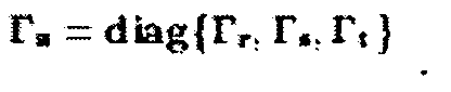
input covariances 330 are derived in Fig. 3 for the
point correspondence and trifocal tensor as measures of uncertainties. In general,
the covariance of the input vector
is a 31 x31 matrix (2 for (x,y), 2 for (x',y')
and 27 for T). When the cross correlation between point correspondence and
trifocal tensor is ignored,
can be written as a block diagonal matrix
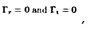
point covariances Γ
r 332 and
334 in the first two
frames can be estimated directly from image intensity (with an unknown scale
factor) as the inverse of the Hessian matrix. More specifically, covariance in the
first image 332 is
where k is a scale factor and the matrix elements are the second-order partial
derivatives of intensity I(x,y) along x and y axes. The Hessian matrix indicates the
curvature of the intensity surface around a feature point.
Covariance 334 can
be estimated similarly in the second frame.
-
The covariance of
trifocal transfer 336 is a function of the camera
parameters. Let the projection matrices of the three cameras be
P1 = [I|0|3×4, P2 = [A|a4|3×4, P3 = [B|b4]3×4
If there is a linear relation
t=DC between vector
t of the trifocal tensor and vector
C of all the distinctive camera parameters, where
then covariance
Γ
t 336 can be computed from the covariance of camera parameters Γ
c by linear
matrix computation Γ
t = DΓ
cD
T . In practice, the relation is nonlinear for
unconstrained camera motion and the availability of Γ
t is an issue.
-
All the partial derivatives and input covariances are fed to the
covariance propagation module 340. In this module, the first order uncertainty of
the input is propagated to the output, finding the impact of the input
perturbation
Δz on the output
Δu
Δu = - [(∂f∂u )(∂f∂u )T]-1(∂f∂u )(∂f∂z )TΔz= -QΔz
Accordingly, the first order covariance of (x",y") 350 becomes
Γu = E{ΔuΔu T} = QΓzQT.
When the cross correlation between point correspondence and trifocal tensor is
ignored, it is further simplified as
Γu = (fufu T)-1fu(fr TΓrfr + fs TΓsfs + ft TΓtft)fu T(fufu T)-1
where
are partial derivatives. It is clear that the
uncertainty of (x",y") is a function of that on (x,y), (x',y') and
T . In practice, the
observation/estimation are used instead of the ground truth for computational
purpose.
-
From the output covariance, we can derive quantitative error
measures for a
single point
360 or the
whole object
370 under a specific camera configuration. The
point covariance
360 indicates which points are more sensitive to the input perturbation, and could
lead to potential improvement. By comparing
object uncertainty 370 at different
camera and scene configurations, we can identify which is the optimal
configuration to achieve minimal transfer uncertainty in frame ψ".
-
Refer now to Fig. 4 for an alternative approach to find the best
achievable performance bound, known as the Cramer-Rao performance bound, for
trifocal transfer at a given noise level. We can not expect performance better than
the predicted bound given the amount of input noise. The task can be carried out
by customizing the general theory of statistical optimization to the specific task of
trifocal transfer.
-
Let (x",y") be the parameters to be estimated from a collection of
data (z
1,z
2, ..., z
N) available from repeated statistical tests on a model
1 400, where i=1,...,N, and assume ε is sampled from a Gaussian
distribution (0, σ
2)410 with the probability density of
The
score 420 by definition is
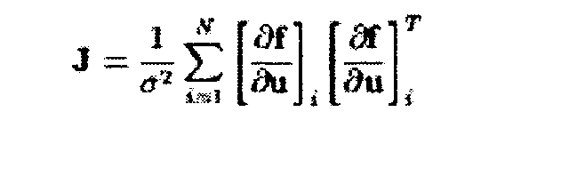
which leads to the
Fisher information matrix 430
The Cramer-Rao performance bound 440 then has the form of
Γu > J-1.
The
output covariance 350 of any unbiased estimator can not be smaller than the
inverse of the Fisher information matrix.
-
Furthermore, the variances of the x and
y components 450 in
closed-form can be derived as
A combination of the covariance propagation in Fig. 3 and the performance low
bound in Fig. 4 gives better results.
-
There are several noisy configurations in practice, depending on the
number of involved noisy and noise-free variables. The different configurations
only change the structure of vector z, and the analysis remains the same.
-
Having presented two methods for error analysis of trifocal transfer
in Fig. 3 and Fig. 4, we now turn to the following specific embodiments to show
how to use the derived error sensitivity measures.
-
Fig. 5 demonstrates how to use the error analysis results to arrange
cameras such that the overall uncertainty of trifocal transfer is minimized. Three
images (220, 230 and 240) of an object 500 in cube [-1,1]3 are taken by several
cameras under perspective projection. Let the three cameras have the same
intrinsic parameters. The center of the world coordinate system is chosen at the
optical center of the camera C1 520. The optical center of the camera C3 540 is
aligned on the X axis, which can be done by rotation of the coordinate system if
necessary. The distances from the center of C1 to the centers of C3 and the cube
500 are R and d, respectively. Another camera C2 530 is introduced for the
trifocal transfer from point p in frame ψ 220 (taken by camera C1) to p" in frame
ψ" 240 (taken by camera C3). If point correspondence and the locations of
cameras C2 and C3 are subject to noise, where should we place camera C2 so that
the transferred points in frame ψ" have the minimum uncertainty? The following
results are tested on a 3-D plane model 550 with 141 nodes as shown in VRML in
Fig. 6.
-
When there is only translational motion and the camera C2 is
placed on a
circle 515 in the YZ plane with radius r, the parameter vector of the
cameras C2 and C3, c= [a 1 / 4, a 2 / 4, a 3 / 4, b 1 / 4, b 2 / 4, b 3 / 4]
T has mean
C = [0, -r cos ,-r sin,
-R,0,0] and covariance
i.e., and the centers of
C2 and C3 are subject to the same identical and independent Gaussian noise
(0,σ
2 c). If points p and p' are also corrupted by Gaussian noise with covariances of
Γ
r=σ 2 / rI
2×2 and Γ
s=σ 2 / sI
2×2, the covariance of point p" can be predicted by linear
matrix computation. With the choice of parameters R=l, d=5R, r=R, and
the overall transfer uncertainty
with
-70°≤0≤75° is evaluated and plotted in Fig. 7. The minimal uncertainty is
reached at min = 6°, by placing the center of C2 somewhere close to (0, r, 0). As
shown in Fig. 8, the uncertainty of trifocal transfer drops as r increases (0 = π/4).
Given the same correspondence precision in frames ψ and ψ', the larger the
baseline between C1 and C2, the smaller the uncertainty of trifocal transfer in
frame ψ". Therefore the question about the location of camera C2 can be
answered quantitatively by using the error analysis results, even though the
optimal location varies with the choices of scene structure and camera
configurations.
-
If the cameras undergo both translational and rotation motion such
that they always point to the cube center (0,0,-d), the camera projection matrix
becomes
where tanα=y/d, tanβ=x/d. Camera C3 is again placed at (R,0,0), and C2 is placed
on a
circle 515 in XY plane in Fig. 5. Using the parameters of
the uncertainty curve of trifocal transfer is shown in Fig. 9, where
the minimal uncertainty is reached at =0 by placing C2 at (0,r,0) on Y axis. The
three perspective projections of the 3-D plane model and the noise associated with
12 selected nodes are depicted in Fig. 10, where camera C2 is placed at =π/3 and
r=R. Given the trifocal tensor and the correspondences of mesh nodes in (a) and
(b), the 2-D mesh model of the plane in (c) can be predicted by trifocal transfer.
Using the error analysis results, we can further predict the uncertainty of the mesh
nodes in (c) from the covariances of point correspondences in (a) and (b). The
shape and orientation of the error distribution (ellipses) in (c) change with , as
camera C2 moves on the circle.
-
In Fig. 11, the trifocal transfer and the associated error uncertainty
on real imagery are demonstrated. Three images (220, 230 and 240) of a static
scene are taken by a moving camera, and the trifocal tensor is recovered by a
random sampling scheme (RANSAC). The position of p" and the associated error
in Fig. 11(c) can be predicted from those in (a) and (b) by trifocal transfer and the
error analysis. In the figure, 15 feature points are detected in (a) then tracked to
(b), and the corresponding points and uncertainty in frame ψ" are shown in (c). It
provides a visualization tool for the error distribution of trifocal transfer (both
magnitude and orientation).
-
In summary, Trifocal transfer finds point/line correspondence
across three images of a rigid scene under perspective projection based on the
geometric constraint of trilinearity, and is useful for applications such as image-based
rendering, virtual navigation, motion estimation and compensation. The
invention discloses methods to determine the error sensitivities associated with
trifocal transfer, i.e. how the uncertainty of point correspondence in the first two
frames and the trifocal tensor affects the corresponding point in the third frame,
and uses the error analysis results for camera planning, system performance
evaluation and trifocal transfer on real imagery. Closed-form analysis is presented
for the first order covariance propagation as well as the Cramer-Rao performance
bound. The quantitative analysis can lead to better understanding of the system
performance in engineering applications.




 The indices repeated in the contravariant (superscript) and covariant (subscript) positions in indicate summation over the range of the index (contraction). For example,
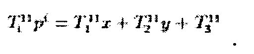
 and
and denote the points in three frames, and let
 denote the vector representation of a trifocal tensor. The trilinear equations can be written as f(u,z) =0, where f is a vector of four trilinear functions and z= [rT, sT, tT]T is a vector of point correspondence and trifocal tensor. The relation between u and z can actually be written as a linear system Au=b, where
 There are four
 The partial derivative of f with respect to point p" in frame ψ" 328 is
 And the partial derivative of f with respect to point

 can be written as a block diagonal matrix
 point covariances Γr 332 and
 334 in the first two frames can be estimated directly from image intensity (with an unknown scale factor) as the inverse of the Hessian matrix. More specifically, covariance in the


 The
The

 A combination of the covariance propagation in Fig. 3 and the performance low bound in Fig. 4 gives better results.
 the overall transfer uncertainty
 with -70°≤0≤75° is evaluated and plotted in Fig. 7. The minimal uncertainty is reached at min = 6°, by placing the center of C2 somewhere close to (0, r, 0). As shown in Fig. 8, the uncertainty of trifocal transfer drops as r increases (0 = π/4). Given the same correspondence precision in frames ψ and ψ', the larger the baseline between C1 and C2, the smaller the uncertainty of trifocal transfer in frame ψ". Therefore the question about the location of camera C2 can be answered quantitatively by using the error analysis results, even though the optimal location varies with the choices of scene structure and camera configurations.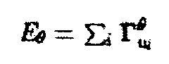

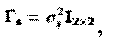 the uncertainty curve of trifocal transfer is shown in Fig. 9, where the minimal uncertainty is reached at =0 by placing C2 at (0,r,0) on Y axis. The three perspective projections of the 3-D plane model and the noise associated with 12 selected nodes are depicted in Fig. 10, where camera C2 is placed at =π/3 and r=R. Given the trifocal tensor and the correspondences of mesh nodes in (a) and (b), the 2-D mesh model of the plane in (c) can be predicted by trifocal transfer. Using the error analysis results, we can further predict the uncertainty of the mesh nodes in (c) from the covariances of point correspondences in (a) and (b). The shape and orientation of the error distribution (ellipses) in (c) change with , as camera C2 moves on the circle.