EP1418352A1 - Rotating shaft device - Google Patents
Rotating shaft device Download PDFInfo
- Publication number
- EP1418352A1 EP1418352A1 EP02755906A EP02755906A EP1418352A1 EP 1418352 A1 EP1418352 A1 EP 1418352A1 EP 02755906 A EP02755906 A EP 02755906A EP 02755906 A EP02755906 A EP 02755906A EP 1418352 A1 EP1418352 A1 EP 1418352A1
- Authority
- EP
- European Patent Office
- Prior art keywords
- shaft
- coolant
- housing
- temperature
- cooling
- Prior art date
- Legal status (The legal status is an assumption and is not a legal conclusion. Google has not performed a legal analysis and makes no representation as to the accuracy of the status listed.)
- Granted
Links
Images


Classifications
-
- B—PERFORMING OPERATIONS; TRANSPORTING
- B23—MACHINE TOOLS; METAL-WORKING NOT OTHERWISE PROVIDED FOR
- B23Q—DETAILS, COMPONENTS, OR ACCESSORIES FOR MACHINE TOOLS, e.g. ARRANGEMENTS FOR COPYING OR CONTROLLING; MACHINE TOOLS IN GENERAL CHARACTERISED BY THE CONSTRUCTION OF PARTICULAR DETAILS OR COMPONENTS; COMBINATIONS OR ASSOCIATIONS OF METAL-WORKING MACHINES, NOT DIRECTED TO A PARTICULAR RESULT
- B23Q11/00—Accessories fitted to machine tools for keeping tools or parts of the machine in good working condition or for cooling work; Safety devices specially combined with or arranged in, or specially adapted for use in connection with, machine tools
- B23Q11/12—Arrangements for cooling or lubricating parts of the machine
- B23Q11/126—Arrangements for cooling or lubricating parts of the machine for cooling only
- B23Q11/127—Arrangements for cooling or lubricating parts of the machine for cooling only for cooling motors or spindles
-
- B—PERFORMING OPERATIONS; TRANSPORTING
- B23—MACHINE TOOLS; METAL-WORKING NOT OTHERWISE PROVIDED FOR
- B23Q—DETAILS, COMPONENTS, OR ACCESSORIES FOR MACHINE TOOLS, e.g. ARRANGEMENTS FOR COPYING OR CONTROLLING; MACHINE TOOLS IN GENERAL CHARACTERISED BY THE CONSTRUCTION OF PARTICULAR DETAILS OR COMPONENTS; COMBINATIONS OR ASSOCIATIONS OF METAL-WORKING MACHINES, NOT DIRECTED TO A PARTICULAR RESULT
- B23Q1/00—Members which are comprised in the general build-up of a form of machine, particularly relatively large fixed members
- B23Q1/25—Movable or adjustable work or tool supports
- B23Q1/26—Movable or adjustable work or tool supports characterised by constructional features relating to the co-operation of relatively movable members; Means for preventing relative movement of such members
- B23Q1/40—Movable or adjustable work or tool supports characterised by constructional features relating to the co-operation of relatively movable members; Means for preventing relative movement of such members using ball, roller or wheel arrangements
-
- B—PERFORMING OPERATIONS; TRANSPORTING
- B23—MACHINE TOOLS; METAL-WORKING NOT OTHERWISE PROVIDED FOR
- B23Q—DETAILS, COMPONENTS, OR ACCESSORIES FOR MACHINE TOOLS, e.g. ARRANGEMENTS FOR COPYING OR CONTROLLING; MACHINE TOOLS IN GENERAL CHARACTERISED BY THE CONSTRUCTION OF PARTICULAR DETAILS OR COMPONENTS; COMBINATIONS OR ASSOCIATIONS OF METAL-WORKING MACHINES, NOT DIRECTED TO A PARTICULAR RESULT
- B23Q1/00—Members which are comprised in the general build-up of a form of machine, particularly relatively large fixed members
- B23Q1/70—Stationary or movable members for carrying working-spindles for attachment of tools or work
-
- F—MECHANICAL ENGINEERING; LIGHTING; HEATING; WEAPONS; BLASTING
- F16—ENGINEERING ELEMENTS AND UNITS; GENERAL MEASURES FOR PRODUCING AND MAINTAINING EFFECTIVE FUNCTIONING OF MACHINES OR INSTALLATIONS; THERMAL INSULATION IN GENERAL
- F16C—SHAFTS; FLEXIBLE SHAFTS; ELEMENTS OR CRANKSHAFT MECHANISMS; ROTARY BODIES OTHER THAN GEARING ELEMENTS; BEARINGS
- F16C19/00—Bearings with rolling contact, for exclusively rotary movement
- F16C19/52—Bearings with rolling contact, for exclusively rotary movement with devices affected by abnormal or undesired conditions
- F16C19/525—Bearings with rolling contact, for exclusively rotary movement with devices affected by abnormal or undesired conditions related to temperature and heat, e.g. insulation
-
- F—MECHANICAL ENGINEERING; LIGHTING; HEATING; WEAPONS; BLASTING
- F16—ENGINEERING ELEMENTS AND UNITS; GENERAL MEASURES FOR PRODUCING AND MAINTAINING EFFECTIVE FUNCTIONING OF MACHINES OR INSTALLATIONS; THERMAL INSULATION IN GENERAL
- F16C—SHAFTS; FLEXIBLE SHAFTS; ELEMENTS OR CRANKSHAFT MECHANISMS; ROTARY BODIES OTHER THAN GEARING ELEMENTS; BEARINGS
- F16C19/00—Bearings with rolling contact, for exclusively rotary movement
- F16C19/54—Systems consisting of a plurality of bearings with rolling friction
-
- F—MECHANICAL ENGINEERING; LIGHTING; HEATING; WEAPONS; BLASTING
- F16—ENGINEERING ELEMENTS AND UNITS; GENERAL MEASURES FOR PRODUCING AND MAINTAINING EFFECTIVE FUNCTIONING OF MACHINES OR INSTALLATIONS; THERMAL INSULATION IN GENERAL
- F16C—SHAFTS; FLEXIBLE SHAFTS; ELEMENTS OR CRANKSHAFT MECHANISMS; ROTARY BODIES OTHER THAN GEARING ELEMENTS; BEARINGS
- F16C25/00—Bearings for exclusively rotary movement adjustable for wear or play
- F16C25/06—Ball or roller bearings
- F16C25/08—Ball or roller bearings self-adjusting
-
- F—MECHANICAL ENGINEERING; LIGHTING; HEATING; WEAPONS; BLASTING
- F16—ENGINEERING ELEMENTS AND UNITS; GENERAL MEASURES FOR PRODUCING AND MAINTAINING EFFECTIVE FUNCTIONING OF MACHINES OR INSTALLATIONS; THERMAL INSULATION IN GENERAL
- F16C—SHAFTS; FLEXIBLE SHAFTS; ELEMENTS OR CRANKSHAFT MECHANISMS; ROTARY BODIES OTHER THAN GEARING ELEMENTS; BEARINGS
- F16C37/00—Cooling of bearings
- F16C37/007—Cooling of bearings of rolling bearings
-
- H—ELECTRICITY
- H02—GENERATION; CONVERSION OR DISTRIBUTION OF ELECTRIC POWER
- H02K—DYNAMO-ELECTRIC MACHINES
- H02K5/00—Casings; Enclosures; Supports
- H02K5/04—Casings or enclosures characterised by the shape, form or construction thereof
- H02K5/16—Means for supporting bearings, e.g. insulating supports or means for fitting bearings in the bearing-shields
- H02K5/173—Means for supporting bearings, e.g. insulating supports or means for fitting bearings in the bearing-shields using bearings with rolling contact, e.g. ball bearings
- H02K5/1732—Means for supporting bearings, e.g. insulating supports or means for fitting bearings in the bearing-shields using bearings with rolling contact, e.g. ball bearings radially supporting the rotary shaft at both ends of the rotor
-
- H—ELECTRICITY
- H02—GENERATION; CONVERSION OR DISTRIBUTION OF ELECTRIC POWER
- H02K—DYNAMO-ELECTRIC MACHINES
- H02K5/00—Casings; Enclosures; Supports
- H02K5/04—Casings or enclosures characterised by the shape, form or construction thereof
- H02K5/16—Means for supporting bearings, e.g. insulating supports or means for fitting bearings in the bearing-shields
- H02K5/173—Means for supporting bearings, e.g. insulating supports or means for fitting bearings in the bearing-shields using bearings with rolling contact, e.g. ball bearings
- H02K5/1737—Means for supporting bearings, e.g. insulating supports or means for fitting bearings in the bearing-shields using bearings with rolling contact, e.g. ball bearings radially supporting the rotor around a fixed spindle; radially supporting the rotor directly
-
- H—ELECTRICITY
- H02—GENERATION; CONVERSION OR DISTRIBUTION OF ELECTRIC POWER
- H02K—DYNAMO-ELECTRIC MACHINES
- H02K7/00—Arrangements for handling mechanical energy structurally associated with dynamo-electric machines, e.g. structural association with mechanical driving motors or auxiliary dynamo-electric machines
- H02K7/08—Structural association with bearings
- H02K7/083—Structural association with bearings radially supporting the rotary shaft at both ends of the rotor
-
- F—MECHANICAL ENGINEERING; LIGHTING; HEATING; WEAPONS; BLASTING
- F16—ENGINEERING ELEMENTS AND UNITS; GENERAL MEASURES FOR PRODUCING AND MAINTAINING EFFECTIVE FUNCTIONING OF MACHINES OR INSTALLATIONS; THERMAL INSULATION IN GENERAL
- F16C—SHAFTS; FLEXIBLE SHAFTS; ELEMENTS OR CRANKSHAFT MECHANISMS; ROTARY BODIES OTHER THAN GEARING ELEMENTS; BEARINGS
- F16C2322/00—Apparatus used in shaping articles
- F16C2322/39—General buildup of machine tools, e.g. spindles, slides, actuators
-
- Y—GENERAL TAGGING OF NEW TECHNOLOGICAL DEVELOPMENTS; GENERAL TAGGING OF CROSS-SECTIONAL TECHNOLOGIES SPANNING OVER SEVERAL SECTIONS OF THE IPC; TECHNICAL SUBJECTS COVERED BY FORMER USPC CROSS-REFERENCE ART COLLECTIONS [XRACs] AND DIGESTS
- Y10—TECHNICAL SUBJECTS COVERED BY FORMER USPC
- Y10S—TECHNICAL SUBJECTS COVERED BY FORMER USPC CROSS-REFERENCE ART COLLECTIONS [XRACs] AND DIGESTS
- Y10S384/00—Bearings
- Y10S384/90—Cooling or heating
-
- Y—GENERAL TAGGING OF NEW TECHNOLOGICAL DEVELOPMENTS; GENERAL TAGGING OF CROSS-SECTIONAL TECHNOLOGIES SPANNING OVER SEVERAL SECTIONS OF THE IPC; TECHNICAL SUBJECTS COVERED BY FORMER USPC CROSS-REFERENCE ART COLLECTIONS [XRACs] AND DIGESTS
- Y10—TECHNICAL SUBJECTS COVERED BY FORMER USPC
- Y10T—TECHNICAL SUBJECTS COVERED BY FORMER US CLASSIFICATION
- Y10T409/00—Gear cutting, milling, or planing
- Y10T409/30—Milling
- Y10T409/303976—Milling with means to control temperature or lubricate
-
- Y—GENERAL TAGGING OF NEW TECHNOLOGICAL DEVELOPMENTS; GENERAL TAGGING OF CROSS-SECTIONAL TECHNOLOGIES SPANNING OVER SEVERAL SECTIONS OF THE IPC; TECHNICAL SUBJECTS COVERED BY FORMER USPC CROSS-REFERENCE ART COLLECTIONS [XRACs] AND DIGESTS
- Y10—TECHNICAL SUBJECTS COVERED BY FORMER USPC
- Y10T—TECHNICAL SUBJECTS COVERED BY FORMER US CLASSIFICATION
- Y10T409/00—Gear cutting, milling, or planing
- Y10T409/30—Milling
- Y10T409/309352—Cutter spindle or spindle support
Definitions
- the invention relates to a rotating shaft apparatus such as a spindle apparatus of a machine tool or an industrial machine.
- Japanese Patent No. 3080253 discloses a spindle which is rotatably supported by a pair of angular ball bearings and a radial ball bearing, at the front and tail end portions of the spindle, respectively.
- a pair of angular ball bearings are disposed at the front side of the spindle.
- Japanese Unexamined Patent Publication (Kokai) No. 7-310742 discloses a configuration of a spindle which is rotatably supported by a pair of angular ball bearings and a cylindrical roller bearing, at the front and tail end portions of the spindle, respectively.
- Japanese Patent No. 2677505 discloses a spindle apparatus of a machine tool in which lubricating liquid is supplied into the spindle from the tail end thereof for the purpose of the cooling of the core portion of the spindle. Then, the lubricating liquid is further used for lubricating the bearings and for cooling the housing rotationally supporting the spindle. Further, Japanese Unexamined Patent Publication (Kokai) No.
- 6-134651 discloses a spindle apparatus which is provided with first and second cooling units for controlling the temperature of a lubricating oil supplied into the space of a bearing, in which space the bearing balls rotate, through a central portion of the spindle, and for controlling the temperature of cooling liquid supplied into a cooling jacket defined in the housing.
- the first and second cooling units are controlled on the basis of the temperatures of the spindle and the housing
- DN value (the product of the inner diameter of a bearing and the rotational speed) becomes higher because the diameter of a shaft and the rotational speed thereof are increased.
- the higher the DN value of a shaft the shorter the life of the bearings supporting the shaft becomes and, therefore, expensive bearings are required.
- contacting angles are defined between the balls and the inner and outer races, which results in spinning motions of the balls and slippage of balls relative to the inner and outer races, which further results in rupturing the lubricating oil film.
- the centrifugal force on the balls affects on the spinning motions of the balls and, therefore, the larger the DN value, the larger the problem becomes in connection with the spinning motions of the balls of an angular ball bearing.
- the radial force acting on the front end portion of a shaft, to which a functional member such as a tool of a machine tool is attached is generally larger than that acting on the tail end portion of the shaft. Therefore, there is a merit in providing the front end portion of a shaft with a diameter larger than that of the tail end portion.
- the larger the diameter of a shaft the larger must be the diameter of the bearing.
- the sizes of the angular bearings must be increased, because the spindle is rotatably supported at the front end portion by the pair of back-to-back angular bearings.
- the spindle is rotatably supported at the tail end portion by the back-to-back angular bearings, the spindle is formed with a constant diameter in the longitudinal direction, and therefore there is a problem, the same as in the first prior art, in connection with the increase in DN value accompanied with the increase in the rotational speed and the diameter of the shaft.
- the temperatures of the spindle (the inner race) and the housing (the outer race) must be precisely controlled.
- the housing is cooled by the lubricating oil, which has been heated by cooling the spindle core. Therefore, a cooling condition of the housing cannot be clearly obtained and optimal control of the temperatures of the spindle and the housing cannot be conducted. Therefore, according to the configuration of the third prior art, there is a problem that an optimal control of the temperatures of the inner and outer races of the bearings, attached to the spindle and the housing, respectively, cannot be conducted.
- the first and second cooling units are controlled on the basis of the detection results from first and second temperature sensors for detecting the housing and the spindle, respectively
- the first and second cooling units of the fourth prior art control the temperatures of the coolant and the lubricating oil so as to reduce the temperature gradient between the housing and the spindle.
- the diameter of an inner race is increased by the centrifugal force in addition to its thermal expansion. Therefore, the temperature of an inner race must be controlled in consideration of the rotational speed of the spindle.
- the temperatures of the inner and outer races are not measured and, therefore, the heat generated by the friction between the inner race, the outer race and the rolling elements cannot be eliminated, which may result in seizure of the bearing.
- the first temperature sensor detects the exterior of the housing and the second temperature sensor detects the outer surface of the front end portion of the spindle. Therefore, the temperature of the heat generating portion in the bearing cannot be precisely detected because the sensors do not detect the temperatures of the inner and outer races of the bearing.
- some rotating shaft apparatuses include a drive motor, that is a built-in motor disposed in the housing for rotationally driving the spindle.
- the housing is heated by the drive motor, in particular by its stator. Therefore, in order to cool the housing of a built-in motor type rotating shaft apparatus, the stator and a portion of the housing adjacent the stator are mainly cooled. However, in some cases, the housing is heated in the contrary by the coolant heated through the cooling of the stator.
- the lubricating liquid which has been heated through the cooling of the spindle core, flows through a spiral passage adjacent the stator.
- the stator cannot be sufficiently cooled by this configuration, and the heated lubricating liquid acts as a thermal medium heating the housing.
- the present invention is directed to solve the above-described problems of the prior art and the objective is to provide a rotating shaft apparatus adapted to a high speed and high rigidity of the shaft.
- the objective of the invention is to provide a rotating shaft apparatus adapted to provide a high speed and high rigidity of the shaft by optimizing the cooling of the shaft and the housing.
- the objective of the invention is to provide a rotating shaft apparatus in which the temperatures of the inner and outer races of the bearings supporting the shaft and the coolant are separately controlled on the basis of detection results to control the internal pressure of the bearings disposed between the shaft and the housing, which prevents damage to the bearings.
- the objective of the invention is to provide a rotating shaft apparatus in which the housing can be optimally cooled.
- the shaft is rotatably supported, at a loaded side, by a cylindrical roller bearing or a radial ball bearing of a large diameter and at the opposite side, by a pair of angular ball bearings of a small diameter.
- the shaft and the housing are cooled.
- inner race temperature detecting means for detecting the temperature of the inner race of the bearing rotationally supporting the shaft at the loaded side and outer race temperature detecting means for detecting the temperature of the outer race of the bearing, rotationally supporting the shaft at the loaded side, are provided to control the internal pressure of the bearing within an appropriate range by controlling the temperature of the coolant, supplied into the cooling passage of the shaft higher than that of the coolant supplied into the cooling passage of the housing, on the basis of the detection results.
- the shaft, the motor and the housing are cooled by separate systems.
- a rotating shaft apparatus for rotationally driving a shaft comprising a housing, a shaft rotatably supported in the housing by a cylindrical roller bearing or a radial ball bearing, which has a larger diameter, at a loaded side and by a pair of angular ball bearings, which have a smaller diameter, at the opposite side and a drive motor for rotationally driving the shaft.
- a rotating shaft apparatus for rotationally driving a shaft comprising a housing, a shaft rotatably supported in the housing by a cylindrical roller bearing or a radial ball bearing, which has a larger diameter, at a loaded side and by a pair of angular ball bearings, which have a smaller diameter, at the opposite side, a drive motor for rotationally driving the shaft, spindle core cooling means, having a cooling passage defined in the shaft along the center axis thereof, for cooling the shaft with a coolant supplied into the coolant passage and housing cooling means, having a coolant passage defined in the housing, for cooling the shaft with the coolant supplied into the coolant passage.
- a rotating shaft apparatus for rotationally driving a shaft comprising a housing, a shaft rotatably supported in the housing by a cylindrical roller bearing or a radial ball bearing, which has a larger diameter, at a loaded side and by a pair of angular ball bearings, which have a smaller diameter, at the opposite side, a drive motor for rotationally driving the shaft, first cooling means, having a cooling passage defined in the shaft along the center axis thereof, for cooling the shaft with a coolant supplied into the coolant passage, second cooling means, having a coolant passage defined in the housing, for cooling the shaft with the coolant supplied into the coolant passage, inner race temperature detecting means for detecting the temperature of the inner race of the bearing for rotationally supporting the shaft at the loaded side, outer race temperature detecting means for detecting the temperature of the outer race of the bearing for rotationally supporting the shaft at the loaded side, the first cooling means controlling the temperature of the coolant to be supplied into the cooling passage of the shaft on the basis of the temperature of
- the second cooling means controls the temperature of the coolant to be supplied into the coolant passage of the housing so that the temperature of the outer race of the bearing is higher that that of the inner race of the bearing by a predetermined temperature.
- a rotating shaft apparatus for rotationally driving a shaft comprising a housing, a shaft rotatably supported in the housing by a plurality of bearings disposed apart from each other, a drive motor for rotationally driving the shaft, first cooling means, having a cooling passage defined in the shaft along the center axis thereof, for cooling the shaft with a coolant supplied into the coolant passage, second cooling means, having a coolant passage defined in the housing, for cooling the shaft with the coolant supplied into the coolant passage, inner race temperature detecting means for detecting the temperature of the inner race of the bearing for rotationally supporting the shaft at the loaded side, outer race temperature detecting means for detecting the temperature of the outer race of the bearing for rotationally supporting the shaft at the loaded side, the first cooling means controlling the temperature of the coolant to be supplied into the cooling passage of the shaft on the basis of the temperature of the inner race detected by the inner race temperature detecting means, and the second cooling means controlling the temperature of the coolant to be supplied into the cooling passage of the housing on the
- the second cooling means preferably controls the temperature of the coolant to be supplied into the coolant passage of the housing so that the temperature of the outer race of the bearing is higher that that of the inner race of the bearing by a predetermined temperature.
- the bearing for the front side of the shaft to which larger load is applied has a larger diameter and the bearing for the rear side to which smaller load is applied has a smaller diameter.
- the front side bearing comprises a cylindrical roller bearing or a radial ball bearing which can bear a high radial load and the rear side bearing comprises a pair of angular ball bearings for receiving the radial and thrust loads. Therefore, the invention provides a rotating shaft apparatus which ensures the rigidity required of rotating shaft apparatuses, reduces the heat generation, and is suitable for high speed rotation. Further, according to the invention, the diameter of the shaft can be reduced to reduce its weight, which allows rapid control of the rotational speed of the shaft. According to the invention, because angular bearings are disposed at the smaller diameter portion of the shaft, relatively small angular bearings can be used to reduce the size of the rotating shaft apparatus and the production cost thereof. Further, according to the invention, the spinning motions of the angular ball bearings are reduced and therefore, the heat generation is also reduced. Therefore, a rotating shaft apparatus which is improved to increase its durability, reliability and rotational speed with relatively high DN value is realized.
- the cooling of the shaft and the housing allows the thermal deformation in the shaft and the housing to be reduced. Therefore, a rotating shaft apparatus which can rotate at a high speed with high precision is realized.
- the temperatures of the inner and outer races of the bearing can be directly detected and, on the basis of the detection results, the coolant supplied into the cooling passages in the shaft and the housing is controlled. Therefore, the coolant temperature can be precisely controlled. This allows the control of the internal pressure of the bearing, rotationally supporting the shaft, within an appropriate range, which reduces the heat generation due to the friction between the inner race, the outer race and the rolling elements to prevent the damage to the bearing when heat is generated during high speed rotation of the shaft. Therefore, the shaft can rotate at high speed because the heat generated in the bearing is reduced.
- the shaft with shaft cooling means and by providing the housing with motor cooling means and housing cooling means, the motor which generates much heat and the housing can be effectively cooled by the coolant supplied into the shaft, the motor and the housing through separate systems. Further, the shaft and the housing can be cooled separately from each other. Therefore, a precise rotating shaft apparatus is realized by reducing the thermal deformations in the shaft and in the housing.
- a rotating shaft apparatus 11 comprises a shaft 17 rotatably supported by bearings 19 and 21 within a housing 13 and 15.
- the housing 13 and 15 has a housing body 13 and a rear cover 15 for closing the rear open end of the housing body 13.
- the shaft 17 has a front end portion 17a, a rear end portion 17b opposite to the front end portion 17a and an intermediate potion 17c between the front and rear end portions 17a and 17b.
- a functional member such as a tool (not shown) of the machine tool is attached to the front end portion 17a (loaded side) of the shaft 17.
- the housing body 13 accommodates a drive motor 23 for rotationally driving the shaft 17 about its central axis O.
- the drive motor 23 has a rotor 23a secured to the intermediate potion 17c of the shaft 17 and a stator 23b secured to the inner surface of the housing body 13 facing the rotor 23a.
- the shaft 17 has a diameter,'at the front end portion 17 or a potion adjacent the front end portion 17a, larger than that of the rear end portion 17b or a portion adjacent the rear end portion 17b.
- the diameter of the front end portion 17a is ⁇ 75mm and the diameter of the rear end portion 17b is ⁇ 55mm.
- the front side bearing 19 preferably comprises a radial bearing including an inner race 19a secured to the outer surface of the shaft 17, an outer race 19b secured to the inner surface of the housing 13 and rolling elements 19c disposed between the inner and outer races 19a and 19b.
- a cylindrical roller bearing is shown as the front side bearing 19.
- the front side bearing 19 may comprise a radial ball bearing.
- the rear side bearing 21 comprises back-to-back angular ball bearings, which include inner races 21a secured to the outer surface of the shaft 17, outer races 21b secured to the inner surface of the housing 13 and rolling elements 21c disposed between the inner and outer races 21a and 21b.
- the radially force acting on the front end portion, to which a functional member such as a tool is attached is larger compared to the rear end portion. Therefore, it is advantageous to design a shaft so that the diameter of the front end portion of the shaft is larger than that of the rear end portion.
- the larger the diameter of the shaft the larger must be the size of the bearings.
- the larger angular ball bearings are required. The heat generated in an angular ball bearing increases with DN value, as described above. Further, angular ball bearings are used as pairs, and are very expensive compared with standard radial bearings.
- a machine tool 101 comprises a bed 103 secured to the floor of a factory, a column 105 secured to the top of the bed 103, a table 107, mounted to the top of the bed 103 for linear movements in orthogonal two horizontal directions (X- and Y-axes directions), for mounting a work W.
- a spindle head 201 is mounted to the column 105 for linear movement in the vertical direction (Z-axis direction).
- the table 107 is driven by X- and Y-axes feeding devices (not shown) provided within the bed 103, and the spindle head 201 is driven by a Z-axis feeding device (not shown) provided within the column 105.
- Each of the X-, Y- and Z-axes feeding devices includes a screw shaft (not shown) extending along each of the X-, Y- and Z-axes and a servomotor (not shown) for rotationally driving the screw shaft.
- the servomotors for driving the screw shafts and a spindle drive motor (indicated by 223 in Figure 3) for driving the spindle 205 are controlled by a machine controlling device 113.
- the machine controlling device 113 and an NC device (not shown) further control the whole of the machining process executed by the machine tool 101 as well as the servomotors and the spindle drive motor.
- the spindle head 201 includes a housing 203 mounted to the front face of the column 105 for linear movement in the Z-axis direction and a spindle 205 as a shaft.
- the spindle 205 extends in the Z-axis direction within the housing 203, and a tool T is attached to the front end of the spindle to face the table 107. Further, the spindle 205 is rotatably supported by the housing 203 through bearings 207 and 209 at the front and rear portions, respectively.
- the spindle 205 in order to attach the tool T to the spindle 205, the spindle 205 includes a tapered hole (not shown) for receiving a tapered portion provided at the tail end of a tool holder holding the tool T and a tool securing device including a draw bar is provided within the spindle 205 for securing the tool T or the tool holder within the tapered hole.
- the feeding devices of the machine tool are not limited to the above-described ones and a horizontal rotating axis may be employed.
- the spindle 205 includes a spindle core cooling passage 211 extending along its longitudinal axis.
- a coolant is supplied from a first coolant supply apparatus 109 into the spindle core cooling passage 211 through a rotary joint 213 provided at the tail end of the spindle 205.
- the coolant returns to the first coolant supply apparatus 109 after the coolant flows through the spindle core cooling passage 211 to cool the spindle 205.
- the first coolant supply apparatus 109 includes a tank (not shown) for containing the coolant, a coolant circulation pump (not shown) for feeding the coolant, a coolant temperature controlling device (not shown) for cooling and controlling the coolant temperature to a predetermined temperature.
- the first coolant supply apparatus 109 is connected to the machine controlling device 113 to receive a start-up signal for the first coolant supply apparatus 109 and information relative to the rotational speed N (min -1 ) of the spindle 205.
- the housing 203 comprises a hollow member for accommodating the substantial portion of the spindle 205 and for rotationally supporting the spindle 205 through the bearings 207 and 209.
- the bearings 207 and 209 preferably comprise rolling bearings having inner races 207a and 209a, outer races 207b and 209b and rolling elements 207c and 209c disposed between the inner races 207a and 209a and the outer races 207b and 209b.
- the bearing 207 which supports the front end portion, the loaded side, of the spindle 205, comprises a radial bearing such as a ball bearing comprising a plurality of balls as the rolling elements 207.
- the bearing 209 which rotationally supports the rear end portion of the spindle 205, preferably comprises a pair of back-to-back angular bearings.
- the bearings 207 and 209 are lubricated by an advantageous method such as an oil-air lubrication method.
- the housing 203 defines a housing coolant passage 215.
- a coolant is supplied from a second coolant supply apparatus 111 into the housing coolant passage 215 and returns to the second coolant supply apparatus 111 after it cools the housing 203.
- the second coolant supply apparatus 111 includes, as does the first coolant supply apparatus 109, a tank (not shown) for containing the coolant, a coolant circulation pump (not shown) for feeding the coolant, a coolant temperature controlling device (not shown) for cooling the coolant to be supplied to the housing 203 and controlling the coolant temperature to a predetermined temperature. Further, the second coolant supply apparatus 111 is connected to the machine controlling device 113 to receive a start-up signal for the first coolant supply apparatus 109 and information relative to the rotational speed N (min -1 ) of the spindle 205.
- First cooling means includes the spindle core cooling passage 211, the first coolant supply apparatus 109, and second cooling means includes the housing coolant passage 215 and the second coolant supply apparatus 111.
- a bed temperature sensor 115 for detecting the temperature of the bed 103, is attached to the bed 103 and is connected to the first coolant supply apparatus 109.
- an inner race temperature sensor 119 for detecting the temperature of the inner race 207a of the bearing 207 supporting the front end portion of the spindle 205
- a outer race temperature sensor 121 for detecting the temperature of the outer race 207b of the bearing 207, are provided in the housing 203 of the spindle head 201.
- the inner race temperature sensor 119 is connected to the coolant temperature controlling device of the first coolant supply apparatus 109
- the outer race temperature sensor 121 is connected to the coolant temperature controlling device of the second coolant supply apparatus 111.
- the bed temperature sensor 115 and the outer race temperature sensor 121 may comprise a thermistor or a thermocouple which contacts with the bed 103 and outer race 207 directly to detect the temperatures thereof.
- the inner race temperature 119 preferably comprises a non-contacting temperature sensor such as an infrared temperature sensor to detect the temperature of the inner race 207a in non-contacting manner.
- the temperature of the inner race 207a may be represented by the surface temperature of a portion of the spindle 205 adjacent the inner race 207a.
- the inner and outer race temperature sensors 119 and 121 are preferably disposed at the bearing 207 for the loaded side of the spindle 205 to which a larger load is applied.
- the spindle 205 defines a center bore 205a along the center axis O.
- a draw bar 217 for securing the tool or tool holder T to the front end portion of the spindle 205, extends along the center axis O.
- the draw bar 217 defines a coolant supply passage 217a along the center axis O.
- the coolant supply passage 217a is connected, at its tail end (not shown) to the rotary joint 213.
- the coolant supply passage 217a further has a radially extending outlet port 217b adjacent its front end 217c.
- the bearing is a double-row-type radial bearing having two ball bearings.
- the spindle head 201 comprises a spindle drive motor 223 having a stator 223a secured to the inner surface of the housing 203 and a rotor 223b secured to the outer surface of the spindle 205.
- the inner surface of the center bore 205a preferably defines a spiral groove 205b at the front end portion of the spindle 205, and a sleeve 219 is fitted into the center bore 205a to cover the spiral groove 205b.
- the spiral groove 205b and outer surface of the sleeve 219 defines a spiral passage.
- a connection sleeve 221, having a connection passage 221a, is disposed in the center bore 205a between the sleeve 219 and the draw bar 217.
- the connection passage 221a fluidly connected the outlet port 217b of the draw bar 217 to the front end portion of the spiral passage (the lowermost portion in Figure 3).
- the coolant is supplied through the rotary joint 213 and sequentially flows through the coolant supply conduit 217a and the outlet port 217b of the draw bar 217, the connection passage 221a, the spiral passage and the coolant return passage, as shown by arrows F1 to F4, then returns to the first coolant supply apparatus 109 through the rotary joint 213.
- the spindle core cooling passage 211 comprises the coolant supply conduit 217a, the outlet port 217b, the connection passage 221a, the spiral passage and the coolant return passage.
- the spiral groove 205b In the connection with the spiral passage, by providing the spiral groove 205b, the surface area of the spindle 205 contacting with the coolant is increased to promote heat transfer at the portion having the spiral passage which allows effective cooling of the spindle 205.
- the spiral passage In order to cool the inner race 207a of the bearing 207 through the spindle 205, the spiral passage is preferably disposed at a portion which overlaps at least partially the bearing 207. Further, by forming the spiral groove 205 so that a screw moves toward the tail end relative to the rotational direction of the spindle, a pumping action is obtained, that is, the rotation of the spindle 205 forces the coolant in the spiral passage toward the tail end of the spindle. This facilitates the coolant to flow through the spindle core cooling passage.
- the first and second coolant supply apparatuses 109 and 111 feed the coolant to the spindle core cooling passage 211 and the housing coolant passage 215 at the time of, or prior to, the activation of the spindle drive motor 103.
- the first coolant supply apparatus 109 controls the coolant temperature, on the basis of the temperatures Tb and Ti of the bed 103 and the inner race 207a detected by the bed temperature sensor 115 and the inner race temperature sensor 119 so that the temperature Ti of the inner race 207a becomes equal to the temperature Tb of the bed 103.
- the coolant temperature may be controlled so that the temperature Ti of the inner race 207a becomes equal'to the ambient temperature or a predetermined temperature.
- the second coolant supply apparatus 111 receives information relative to the temperature Ti of the inner race 207a from the first coolant supply apparatus 109 and controls the coolant temperature so that the temperature To of the outer race 207b is higher that the temperature Ti of the inner race 207a by a predetermined temperature difference ⁇ T.
- the temperature difference ⁇ T between the inner and outer races 207a and 207b may be determined to apply an appropriate internal pressure in the bearing relative to the rotational speed N (min -1 ) of the spindle 205.
- the temperature difference ⁇ T may be preliminary determined by an experiment or by a numerical analysis and stored in the second coolant supply apparatus 111 in the form of a function or a table relative to the rotational speed N (min -1 ) of the spindle 205 so that the temperature difference ⁇ T is calculated in the second coolant supply apparatus 111 on the basis of the information relative to the rotational speed N (min -1 ) of the spindle 205 which is received from the machine controlling device 113.
- the temperature of the coolant supplied from the second coolant supply apparatus 111 into the housing coolant passage 215 so that a temperature difference between the inner and outer races 207a and 207b is presented and, in particular, the temperature of the inner race 207a is higher than that of the outer race 207b by ⁇ T, the temperature of the inner race 207a is maintained lower that that of the outer race 207b, which prevents an excess increase in the internal pressure generated by the expansion of the inner race 207a.
- the temperature difference ⁇ T which provides an appropriate internal pressure in the bearing changes according to the rotational speed of the spindle.
- control of the internal pressure in the bearing can be executed more precisely, compared with the above-described fourth prior art in which the temperature difference between the inner and outer races is controlled constantly in the high rotational speed range where the effect of the centrifugal force is increased. This also contribute to an increase in the endurance of the bearing and the reliability of the spindle apparatus.
- the inner race temperature sensor 119 and the outer race temperature sensor 121 for detecting the temperatures Ti and To of the inner and outer races 207a and 207b, are connected to the machine controlling device 113.
- the first coolant supply apparatus 109 receives the information relative to the rotational speed N (min -1 ) of the spindle 205 and the temperature Ti of the inner race 207a from the machine controlling device 113 and the temperature Tb of the bed 103 from the bed temperature sensor 115, and controls the coolant temperature so that the temperature Ti of the inner race 207a becomes equal to the temperature Tb of the bed 103.
- the coolant temperature may be controlled so that the temperature Ti of the inner race 207a becomes equal to the ambient temperature or a predetermined temperature.
- the second coolant supply apparatus 111 receives the information relative to the temperature Ti of the inner race 207a from the machine controlling device 113 and controls the coolant temperature so that the temperature To of the outer race 207b becomes higher than the temperature Ti of the inner race 207a by the predetermined temperature difference ⁇ T.
- an anomaly may be detected and displayed when the temperature difference between the inner and outer races 207a and 207b is at or higher than a predetermined value on the basis of the temperatures of the inner and outer races 207a and 207b detected by the inner race temperature sensor 119 and outer race temperature sensor 121.
- the coolant temperature may be controlled so that the temperature of the outer race 207b becomes lower than that of the inner race 207a by ⁇ T. whereas in the above-described first and second embodiments, the coolant temperature is controlled so that the temperature of the inner race 207a becomes higher than that of the outer race 207b by ⁇ T.
- the spindle core cooling passage and the housing coolant passage may be provided in the shaft 17 and the housing 13, respectively, to cool the shaft 17 and housing 13.
- a single coolant supply apparatus or two coolant supply apparatuses, as shown in Figures 2 and 4 may feed the coolant into the spindle core cooling passage and the housing coolant passage. The thermal deformation of the shaft 17 and the housing 13 can be reduced by cooling them.
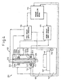
- a spindle apparatus 301 as the rotating shaft apparatus comprises a spindle 305 rotatably supported in a housing 303, 319 and 321 by bearings 307 and 309.
- the spindle 305 may haes large and small diameter portions at the front and tail end portions thereof, respectively, the front large diameter portion being rotatably supported a radial bearing (bearing 307) and rear small diameter portion being rotatably supported by a pair of angular bearings (bearing 309).
- the housing 303, 319 and 321 has a housing body 303, a front cover 319 closing the front open end of the housing body 303 and a rear cover 321 closing the rear open end of the housing body 303.
- the spindle 305 defines a spindle core cooling passage 311 extending along the center axis, a front outlet port 311a extending radially from the spindle core cooling passage 311 at the front end portion of the spindle 305 and a rear outlet port 311b extending radially from the spindle core cooling passage 311 at the rear end portion of the spindle 305.
- a drive motor 317 for rotationally driving the spindle 305 is disposed within the housing body 303.
- the drive motor 317 has a rotor 317a secured to the spindle 305 and a stator 317b secured to the inner surface of the housing body 303 facing the rotor 317a.
- the housing body 303 includes a spiral groove 313 defined in the inner surface of the housing body 303 disposed in a region where the stator 317b is disposed so as to define a spiral motor coolant passage 313 between the spiral groove 313 and the outer surface of the stator 317b.
- the housing body 303 further includes a housing coolant passage 315 defined by a cavity which is disposed to encompass the spiral motor coolant passage 313. Further, an outlet passage 319a is defined in the front cover 319 of the housing to fluidly communicate with the front outlet port 311a.
- the spindle core cooling passage 311 is fluidly connected to a rotary joint 333 attached to the tail end of the spindle 305 so that the coolant is supplied into the spindle core cooling passage 311 from a coolant supply apparatus 323, having a tank 323a and a coolant circulation pump 323b, through a coolant supply conduit 325, a spindle core coolant supply conduit 325a and the rotary joint 333.
- a portion of the coolant supplied into the spindle core cooling passage 311 returns to the coolant supply apparatus 323 through the front outlet port 311a, the outlet passage 319a and a coolant return conduit 327.
- the rest of the coolant supplied into the spindle core cooling passage 311 returns to the coolant supply apparatus 323 through the rear outlet port 311b and the coolant return conduit 327.
- the coolant circulation pump 323c of the coolant supply apparatus 323 feeds the coolant into the motor coolant passage 313 through a coolant supply conduit 331 and a motor coolant conduit 325b. At that time, a configuration may be conceived which allows the coolant supplied into the spiral motor coolant passage 313 to flow toward the rear end of the housing body 303 from the front end thereof.
- the coolant circulation pump 323c of the coolant supply apparatus 323 feeds the coolant into the housing coolant passage 315 through the coolant supply conduit 331 and a housing coolant supply conduit 325c.
- the coolant supplied into the motor coolant passage 313 and the housing coolant passage 315 returns to the coolant supply apparatus 323 through a housing coolant return conduit 329.
- the coolant circulation pump for the motor coolant passage 313 and the housing coolant passage 315 may comprise separate pumps.
- the housing coolant passage 315 is disposed radially outside of the motor coolant passage 313 so as to encompass it, and the coolant supplied into the motor coolant passage 313 removes the heat generated in the stator 317b, which prevents heat transfer to a substantial portion of the housing body 303. Further, the coolant supplied into the housing coolant passage 315 cools the housing body 303. Therefore, the thermal deformation of the housing body 303 due to the heat generation in the stator 317b is prevented.
- a rotor coolant passage may be defined in the spindle 305, for the rotor 317a, so as to cool the rotor 317a by introducing the coolant from the spindle core cooling passage 311 into the rotor coolant passage.
Landscapes
- Engineering & Computer Science (AREA)
- General Engineering & Computer Science (AREA)
- Mechanical Engineering (AREA)
- Power Engineering (AREA)
- Auxiliary Devices For Machine Tools (AREA)
- Mounting Of Bearings Or Others (AREA)
- Turning (AREA)
- Rolling Contact Bearings (AREA)
- Harvester Elements (AREA)
- Rotary Pumps (AREA)
- Compressors, Vaccum Pumps And Other Relevant Systems (AREA)
Abstract
Description
- The invention relates to a rotating shaft apparatus such as a spindle apparatus of a machine tool or an industrial machine.
- The shaft of a rotating shaft apparatus, such as a spindle of a machine tool, receives radial and thrust load. Therefore, the bearings rotationally supporting the shaft are determined in consideration of such loads. For example, Japanese Patent No. 3080253, as a first prior art, discloses a spindle which is rotatably supported by a pair of angular ball bearings and a radial ball bearing, at the front and tail end portions of the spindle, respectively. In general, a pair of angular ball bearings are disposed at the front side of the spindle. Further, Japanese Unexamined Patent Publication (Kokai) No. 7-310742, as a second prior art, discloses a configuration of a spindle which is rotatably supported by a pair of angular ball bearings and a cylindrical roller bearing, at the front and tail end portions of the spindle, respectively.
- Japanese Patent No. 2677505, as a third prior art, discloses a spindle apparatus of a machine tool in which lubricating liquid is supplied into the spindle from the tail end thereof for the purpose of the cooling of the core portion of the spindle. Then, the lubricating liquid is further used for lubricating the bearings and for cooling the housing rotationally supporting the spindle. Further, Japanese Unexamined Patent Publication (Kokai) No. 6-134651, as a fourth prior art, discloses a spindle apparatus which is provided with first and second cooling units for controlling the temperature of a lubricating oil supplied into the space of a bearing, in which space the bearing balls rotate, through a central portion of the spindle, and for controlling the temperature of cooling liquid supplied into a cooling jacket defined in the housing. The first and second cooling units are controlled on the basis of the temperatures of the spindle and the housing
- Recently, in the field of rotating shaft apparatuses for machine tools, increasing in the rotational speed of the shaft has been required and, therefore, the loads, on the bearings for rotationally supporting the shaft, have been also increased according to the increase in the rotational speed. Thus, DN value (the product of the inner diameter of a bearing and the rotational speed) becomes higher because the diameter of a shaft and the rotational speed thereof are increased. The higher the DN value of a shaft, the shorter the life of the bearings supporting the shaft becomes and, therefore, expensive bearings are required. Particularly, in an angular ball bearing, contacting angles are defined between the balls and the inner and outer races, which results in spinning motions of the balls and slippage of balls relative to the inner and outer races, which further results in rupturing the lubricating oil film. The centrifugal force on the balls affects on the spinning motions of the balls and, therefore, the larger the DN value, the larger the problem becomes in connection with the spinning motions of the balls of an angular ball bearing.
- Further, the radial force acting on the front end portion of a shaft, to which a functional member such as a tool of a machine tool is attached, is generally larger than that acting on the tail end portion of the shaft. Therefore, there is a merit in providing the front end portion of a shaft with a diameter larger than that of the tail end portion. However, the larger the diameter of a shaft, the larger must be the diameter of the bearing. In this connection, according to the first prior art, the sizes of the angular bearings must be increased, because the spindle is rotatably supported at the front end portion by the pair of back-to-back angular bearings.
- According to the second prior art, although the spindle is rotatably supported at the tail end portion by the back-to-back angular bearings, the spindle is formed with a constant diameter in the longitudinal direction, and therefore there is a problem, the same as in the first prior art, in connection with the increase in DN value accompanied with the increase in the rotational speed and the diameter of the shaft.
- On the other hand, in high-speed rotating shaft apparatuses of which rotational speed is higher than 20,000 min-1, such as recent spindle apparatuses of machine tools, the internal pressure generated in the bearings for rotationally supporting the shaft must be strictly controlled. In particular, the higher the rotational speed of a shaft, the larger the outer diameters of the inner races of bearings supporting the shaft become due to the centrifugal force and the thermal expansion thereof. On the other hand, the outer diameter of the outer races is restrained by the housing. Therefore, the inner diameter of the outer race is not increased by the centrifugal force. Further, the housings of the most high speed rotating shaft apparatuses are cooled. In such a case, if the housing is too cool, excessive internal pressure is applied to the rolling elements disposed between the inner and outer races, because the outer race cannot thermally expand. Therefore, the internal race and the rolling elements are urged to the outer race so that the heat generation due to the friction between the inner race, the outer race and the rolling elements is increased, which results in damage to the bearing.
- Thus, in order to prevent the excessive internal pressure on the rolling elements of a bearing, the temperatures of the spindle (the inner race) and the housing (the outer race) must be precisely controlled. In this connection, according to the third prior art, the housing is cooled by the lubricating oil, which has been heated by cooling the spindle core. Therefore, a cooling condition of the housing cannot be clearly obtained and optimal control of the temperatures of the spindle and the housing cannot be conducted. Therefore, according to the configuration of the third prior art, there is a problem that an optimal control of the temperatures of the inner and outer races of the bearings, attached to the spindle and the housing, respectively, cannot be conducted.
- In this connection, according to the fourth prior art, although the first and second cooling units are controlled on the basis of the detection results from first and second temperature sensors for detecting the housing and the spindle, respectively, the first and second cooling units of the fourth prior art control the temperatures of the coolant and the lubricating oil so as to reduce the temperature gradient between the housing and the spindle. As described above, the diameter of an inner race is increased by the centrifugal force in addition to its thermal expansion. Therefore, the temperature of an inner race must be controlled in consideration of the rotational speed of the spindle. However, according to the fourth prior art, the temperatures of the inner and outer races are not measured and, therefore, the heat generated by the friction between the inner race, the outer race and the rolling elements cannot be eliminated, which may result in seizure of the bearing. Further, in the fourth prior art, the first temperature sensor detects the exterior of the housing and the second temperature sensor detects the outer surface of the front end portion of the spindle. Therefore, the temperature of the heat generating portion in the bearing cannot be precisely detected because the sensors do not detect the temperatures of the inner and outer races of the bearing.
- Further, some rotating shaft apparatuses include a drive motor, that is a built-in motor disposed in the housing for rotationally driving the spindle. In such a built-in motor type rotating shaft apparatus, the housing is heated by the drive motor, in particular by its stator. Therefore, in order to cool the housing of a built-in motor type rotating shaft apparatus, the stator and a portion of the housing adjacent the stator are mainly cooled. However, in some cases, the housing is heated in the contrary by the coolant heated through the cooling of the stator. According to the third prior art, the lubricating liquid, which has been heated through the cooling of the spindle core, flows through a spiral passage adjacent the stator. However, the stator cannot be sufficiently cooled by this configuration, and the heated lubricating liquid acts as a thermal medium heating the housing.
- The present invention is directed to solve the above-described problems of the prior art and the objective is to provide a rotating shaft apparatus adapted to a high speed and high rigidity of the shaft.
- Further, the objective of the invention is to provide a rotating shaft apparatus adapted to provide a high speed and high rigidity of the shaft by optimizing the cooling of the shaft and the housing.
- Further, the objective of the invention is to provide a rotating shaft apparatus in which the temperatures of the inner and outer races of the bearings supporting the shaft and the coolant are separately controlled on the basis of detection results to control the internal pressure of the bearings disposed between the shaft and the housing, which prevents damage to the bearings.
- Further, the objective of the invention is to provide a rotating shaft apparatus in which the housing can be optimally cooled.
- In order to achieve the above-described objectives, according to the present invention, the shaft is rotatably supported, at a loaded side, by a cylindrical roller bearing or a radial ball bearing of a large diameter and at the opposite side, by a pair of angular ball bearings of a small diameter.
- Further, according to the invention, the shaft and the housing are cooled.
- Further, according to the invention, inner race temperature detecting means for detecting the temperature of the inner race of the bearing rotationally supporting the shaft at the loaded side, and outer race temperature detecting means for detecting the temperature of the outer race of the bearing, rotationally supporting the shaft at the loaded side, are provided to control the internal pressure of the bearing within an appropriate range by controlling the temperature of the coolant, supplied into the cooling passage of the shaft higher than that of the coolant supplied into the cooling passage of the housing, on the basis of the detection results.
- Further, in the present invention, the shaft, the motor and the housing are cooled by separate systems.
- According to the invention, there is provided a rotating shaft apparatus for rotationally driving a shaft comprising a housing, a shaft rotatably supported in the housing by a cylindrical roller bearing or a radial ball bearing, which has a larger diameter, at a loaded side and by a pair of angular ball bearings, which have a smaller diameter, at the opposite side and a drive motor for rotationally driving the shaft.
- According to the invention, there is provided a rotating shaft apparatus for rotationally driving a shaft comprising a housing, a shaft rotatably supported in the housing by a cylindrical roller bearing or a radial ball bearing, which has a larger diameter, at a loaded side and by a pair of angular ball bearings, which have a smaller diameter, at the opposite side, a drive motor for rotationally driving the shaft, spindle core cooling means, having a cooling passage defined in the shaft along the center axis thereof, for cooling the shaft with a coolant supplied into the coolant passage and housing cooling means, having a coolant passage defined in the housing, for cooling the shaft with the coolant supplied into the coolant passage.
- Further, according to the invention, there is provided a rotating shaft apparatus for rotationally driving a shaft comprising a housing, a shaft rotatably supported in the housing by a cylindrical roller bearing or a radial ball bearing, which has a larger diameter, at a loaded side and by a pair of angular ball bearings, which have a smaller diameter, at the opposite side, a drive motor for rotationally driving the shaft, first cooling means, having a cooling passage defined in the shaft along the center axis thereof, for cooling the shaft with a coolant supplied into the coolant passage, second cooling means, having a coolant passage defined in the housing, for cooling the shaft with the coolant supplied into the coolant passage, inner race temperature detecting means for detecting the temperature of the inner race of the bearing for rotationally supporting the shaft at the loaded side, outer race temperature detecting means for detecting the temperature of the outer race of the bearing for rotationally supporting the shaft at the loaded side, the first cooling means controlling the temperature of the coolant to be supplied into the cooling passage of the shaft on the basis of the temperature of the inner race detected by the inner race temperature detecting means, and the second cooling means controlling the temperature of the coolant to be supplied into the cooling passage of the housing on the basis of the temperature of the outer race detected by the outer race temperature detecting means.
- When a shaft rotates at a high speed, the inner race of a bearing is expanded by the centrifugal force, and the rolling elements are urged to the outer race. According to the invention, the second cooling means controls the temperature of the coolant to be supplied into the coolant passage of the housing so that the temperature of the outer race of the bearing is higher that that of the inner race of the bearing by a predetermined temperature.
- Further, according to the invention, there is provided a rotating shaft apparatus for rotationally driving a shaft comprising a housing, a shaft rotatably supported by the housing through bearings, a drive motor, having a stator secured to the housing and a rotator secured to the shaft to face to the stator, for rotationally driving the shaft, shaft cooling means, having a cooling passage defined in the shaft along the center axis thereof, for cooling the shaft with a coolant supplied into the coolant passage, motor cooling means, disposed in the housing and having coolant passage for cooling the periphery of the stator, for cooling the motor with the coolant supplied into the coolant passage and housing cooling means, disposed in the housing and having a coolant passage dispose outside of the motor cooling means, for cooling the housing with the coolant supplied into the coolant passage.
- Further, according to the invention, there is provided a rotating shaft apparatus for rotationally driving a shaft comprising a housing, a shaft rotatably supported in the housing by a plurality of bearings disposed apart from each other, a drive motor for rotationally driving the shaft, first cooling means, having a cooling passage defined in the shaft along the center axis thereof, for cooling the shaft with a coolant supplied into the coolant passage, second cooling means, having a coolant passage defined in the housing, for cooling the shaft with the coolant supplied into the coolant passage, inner race temperature detecting means for detecting the temperature of the inner race of the bearing for rotationally supporting the shaft at the loaded side, outer race temperature detecting means for detecting the temperature of the outer race of the bearing for rotationally supporting the shaft at the loaded side, the first cooling means controlling the temperature of the coolant to be supplied into the cooling passage of the shaft on the basis of the temperature of the inner race detected by the inner race temperature detecting means, and the second cooling means controlling the temperature of the coolant to be supplied into the cooling passage of the housing on the basis of the temperature of the outer race detected by the outer race temperature detecting means.
- The second cooling means preferably controls the temperature of the coolant to be supplied into the coolant passage of the housing so that the temperature of the outer race of the bearing is higher that that of the inner race of the bearing by a predetermined temperature.
- The bearing for the front side of the shaft to which larger load is applied has a larger diameter and the bearing for the rear side to which smaller load is applied has a smaller diameter.
- The front side bearing comprises a cylindrical roller bearing or a radial ball bearing which can bear a high radial load and the rear side bearing comprises a pair of angular ball bearings for receiving the radial and thrust loads. Therefore, the invention provides a rotating shaft apparatus which ensures the rigidity required of rotating shaft apparatuses, reduces the heat generation, and is suitable for high speed rotation. Further, according to the invention, the diameter of the shaft can be reduced to reduce its weight, which allows rapid control of the rotational speed of the shaft. According to the invention, because angular bearings are disposed at the smaller diameter portion of the shaft, relatively small angular bearings can be used to reduce the size of the rotating shaft apparatus and the production cost thereof. Further, according to the invention, the spinning motions of the angular ball bearings are reduced and therefore, the heat generation is also reduced. Therefore, a rotating shaft apparatus which is improved to increase its durability, reliability and rotational speed with relatively high DN value is realized.
- The cooling of the shaft and the housing allows the thermal deformation in the shaft and the housing to be reduced. Therefore, a rotating shaft apparatus which can rotate at a high speed with high precision is realized.
- According to the invention, the temperatures of the inner and outer races of the bearing can be directly detected and, on the basis of the detection results, the coolant supplied into the cooling passages in the shaft and the housing is controlled. Therefore, the coolant temperature can be precisely controlled. This allows the control of the internal pressure of the bearing, rotationally supporting the shaft, within an appropriate range, which reduces the heat generation due to the friction between the inner race, the outer race and the rolling elements to prevent the damage to the bearing when heat is generated during high speed rotation of the shaft. Therefore, the shaft can rotate at high speed because the heat generated in the bearing is reduced.
- By lowering the temperature of the inner race of the bearing to lower than that of the outer race, the pressure on the rolling elements to the outer race, due to the thermal expansion, is reduced. This allows an appropriate internal pressure of the bearing and reduces the heat generation, due to the friction, between the outer race and the rolling elements of the bearing, which prevents damage to the bearing.
- According to the invention, by providing the shaft with shaft cooling means and by providing the housing with motor cooling means and housing cooling means, the motor which generates much heat and the housing can be effectively cooled by the coolant supplied into the shaft, the motor and the housing through separate systems. Further, the shaft and the housing can be cooled separately from each other. Therefore, a precise rotating shaft apparatus is realized by reducing the thermal deformations in the shaft and in the housing.
-
- Figure 1 is a section of a preferable embodiment of a rotating shaft apparatus.
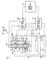
- Figure 2 is a schematic diagram of a machine tool which is provided with a rotating shaft apparatus of the invention.
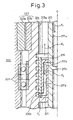
- Figure 3 is a partial section of the front end portion of the spindle of the machine tool of Figure 2, showing a spindle core cooling passage provided with a spiral passage.
- Figure 4 is a schematic diagram of another embodiment of a machine tool which is provided with a rotating shaft apparatus of the invention.
- Figure 5 is a section of another embodiment of a rotating shaft apparatus according to the invention.
-
- With reference to the drawings, a preferred embodiment of the invention will be described below. In this connection, in the embodiment described below, a spindle apparatus of a machine tool is described as an example of the rotating shaft apparatus.
- With reference to Figure 1, a
rotating shaft apparatus 11 comprises ashaft 17 rotatably supported bybearings housing housing housing body 13 and arear cover 15 for closing the rear open end of thehousing body 13. Theshaft 17 has afront end portion 17a, a rear end portion 17b opposite to thefront end portion 17a and anintermediate potion 17c between the front andrear end portions 17a and 17b. A functional member such as a tool (not shown) of the machine tool is attached to thefront end portion 17a (loaded side) of theshaft 17. Thehousing body 13 accommodates adrive motor 23 for rotationally driving theshaft 17 about its central axis O. Thedrive motor 23 has arotor 23a secured to theintermediate potion 17c of theshaft 17 and astator 23b secured to the inner surface of thehousing body 13 facing therotor 23a. - In this embodiment, the
shaft 17 has a diameter,'at thefront end portion 17 or a potion adjacent thefront end portion 17a, larger than that of the rear end portion 17b or a portion adjacent the rear end portion 17b. In this particular embodiment, the diameter of thefront end portion 17a is ϕ75mm and the diameter of the rear end portion 17b is ϕ55mm. On the other hand, thebearings shaft 17, including a front side bearing 19 for rotationally supporting the front end portion or a portion adjacent the front end portion of theshaft 17 and a rear side bearing 21 for rotationally supporting the rear end portion 17b or a portion adjacent the rear end portion of theshaft 17. The front side bearing 19 preferably comprises a radial bearing including aninner race 19a secured to the outer surface of theshaft 17, anouter race 19b secured to the inner surface of thehousing 13 and rollingelements 19c disposed between the inner andouter races front side bearing 19. The front side bearing 19 may comprise a radial ball bearing. The rear side bearing 21 comprises back-to-back angular ball bearings, which includeinner races 21a secured to the outer surface of theshaft 17,outer races 21b secured to the inner surface of thehousing 13 and rollingelements 21c disposed between the inner andouter races - In general, in rotating shaft apparatuses, the radially force acting on the front end portion, to which a functional member such as a tool is attached, is larger compared to the rear end portion. Therefore, it is advantageous to design a shaft so that the diameter of the front end portion of the shaft is larger than that of the rear end portion. However, the larger the diameter of the shaft, the larger must be the size of the bearings. In particular, if the front side of the shaft is supported by back-to-back angular ball bearings, the larger angular ball bearings are required. The heat generated in an angular ball bearing increases with DN value, as described above. Further, angular ball bearings are used as pairs, and are very expensive compared with standard radial bearings. Therefore, rotationally supporting the front side of a shaft by angular bearings considerably increases the cost of a rotating shaft apparatus. on the other hand, the radial force acting on the rear side of a shaft is much smaller than that acting on the front side, and therefore the diameter can be reduced. Therefore, if the rear end portion or a portion adjacent the rear end portion 17b of the
shaft 17 by a pair of back-to-back angular ball bearings to bear the radial load in the radial direction and the thrust load in the axial direction, the sizes of the angular bearings can be reduced so as to reduce the heat generation, because of the smaller DN value, and the cost of the rotating shaft apparatus. - With reference to Figure 2, an application of a rotating shaft apparatus according to the invention to a machine tool will be described below.
- In Figure 2, a
machine tool 101 comprises abed 103 secured to the floor of a factory, acolumn 105 secured to the top of thebed 103, a table 107, mounted to the top of thebed 103 for linear movements in orthogonal two horizontal directions (X- and Y-axes directions), for mounting a work W. Aspindle head 201 is mounted to thecolumn 105 for linear movement in the vertical direction (Z-axis direction). The table 107 is driven by X- and Y-axes feeding devices (not shown) provided within thebed 103, and thespindle head 201 is driven by a Z-axis feeding device (not shown) provided within thecolumn 105. Each of the X-, Y- and Z-axes feeding devices includes a screw shaft (not shown) extending along each of the X-, Y- and Z-axes and a servomotor (not shown) for rotationally driving the screw shaft. The servomotors for driving the screw shafts and a spindle drive motor (indicated by 223 in Figure 3) for driving thespindle 205 are controlled by amachine controlling device 113. Themachine controlling device 113 and an NC device (not shown) further control the whole of the machining process executed by themachine tool 101 as well as the servomotors and the spindle drive motor. - The
spindle head 201 includes ahousing 203 mounted to the front face of thecolumn 105 for linear movement in the Z-axis direction and aspindle 205 as a shaft. Thespindle 205 extends in the Z-axis direction within thehousing 203, and a tool T is attached to the front end of the spindle to face the table 107. Further, thespindle 205 is rotatably supported by thehousing 203 throughbearings spindle 205, thespindle 205 includes a tapered hole (not shown) for receiving a tapered portion provided at the tail end of a tool holder holding the tool T and a tool securing device including a draw bar is provided within thespindle 205 for securing the tool T or the tool holder within the tapered hole. Incidentally, the feeding devices of the machine tool are not limited to the above-described ones and a horizontal rotating axis may be employed. - Further, the
spindle 205 includes a spindlecore cooling passage 211 extending along its longitudinal axis. A coolant is supplied from a firstcoolant supply apparatus 109 into the spindlecore cooling passage 211 through a rotary joint 213 provided at the tail end of thespindle 205. The coolant returns to the firstcoolant supply apparatus 109 after the coolant flows through the spindlecore cooling passage 211 to cool thespindle 205. The firstcoolant supply apparatus 109 includes a tank (not shown) for containing the coolant, a coolant circulation pump (not shown) for feeding the coolant, a coolant temperature controlling device (not shown) for cooling and controlling the coolant temperature to a predetermined temperature. Further, the firstcoolant supply apparatus 109 is connected to themachine controlling device 113 to receive a start-up signal for the firstcoolant supply apparatus 109 and information relative to the rotational speed N (min-1) of thespindle 205. - The
housing 203 comprises a hollow member for accommodating the substantial portion of thespindle 205 and for rotationally supporting thespindle 205 through thebearings spindle 205 at a speed of above 20,000 min-1, thebearings inner races outer races elements inner races outer races bearing 207, which supports the front end portion, the loaded side, of thespindle 205, comprises a radial bearing such as a ball bearing comprising a plurality of balls as the rollingelements 207. On the other hand, thebearing 209, which rotationally supports the rear end portion of thespindle 205, preferably comprises a pair of back-to-back angular bearings. Thebearings - The
housing 203 defines a housing coolant passage 215. A coolant is supplied from a secondcoolant supply apparatus 111 into the housing coolant passage 215 and returns to the secondcoolant supply apparatus 111 after it cools thehousing 203. The secondcoolant supply apparatus 111 includes, as does the firstcoolant supply apparatus 109, a tank (not shown) for containing the coolant, a coolant circulation pump (not shown) for feeding the coolant, a coolant temperature controlling device (not shown) for cooling the coolant to be supplied to thehousing 203 and controlling the coolant temperature to a predetermined temperature. Further, the secondcoolant supply apparatus 111 is connected to themachine controlling device 113 to receive a start-up signal for the firstcoolant supply apparatus 109 and information relative to the rotational speed N (min-1) of thespindle 205. - First cooling means, described in claim 3, includes the spindle
core cooling passage 211, the firstcoolant supply apparatus 109, and second cooling means includes the housing coolant passage 215 and the secondcoolant supply apparatus 111. - A
bed temperature sensor 115, for detecting the temperature of thebed 103, is attached to thebed 103 and is connected to the firstcoolant supply apparatus 109. On the other hand, an innerrace temperature sensor 119, for detecting the temperature of theinner race 207a of thebearing 207 supporting the front end portion of thespindle 205, and a outer race temperature sensor 121, for detecting the temperature of theouter race 207b of thebearing 207, are provided in thehousing 203 of thespindle head 201. The innerrace temperature sensor 119 is connected to the coolant temperature controlling device of the firstcoolant supply apparatus 109, and the outer race temperature sensor 121 is connected to the coolant temperature controlling device of the secondcoolant supply apparatus 111. Thebed temperature sensor 115 and the outer race temperature sensor 121 may comprise a thermistor or a thermocouple which contacts with thebed 103 andouter race 207 directly to detect the temperatures thereof. Theinner race temperature 119 preferably comprises a non-contacting temperature sensor such as an infrared temperature sensor to detect the temperature of theinner race 207a in non-contacting manner. The temperature of theinner race 207a may be represented by the surface temperature of a portion of thespindle 205 adjacent theinner race 207a. The inner and outerrace temperature sensors 119 and 121 are preferably disposed at thebearing 207 for the loaded side of thespindle 205 to which a larger load is applied. - With reference to Figure 3, an enlarged half section of the front end portion of the
spindle 205 is indicated by reference "A" in Figure 2. Thespindle 205 defines acenter bore 205a along the center axis O. In the center bore 205a, adraw bar 217, for securing the tool or tool holder T to the front end portion of thespindle 205, extends along the center axis O. Thedraw bar 217 defines a coolant supply passage 217a along the center axis O. The coolant supply passage 217a is connected, at its tail end (not shown) to the rotary joint 213. The coolant supply passage 217a further has a radially extending outlet port 217b adjacent itsfront end 217c. As shown in Figure 3, by inserting thedraw bar 217 into the center bore 205a of thespindle 205, a coolant return passage is defined between the outer surface of thedraw bar 217 and the inner surface of the center bore 205a. Incidentally, in the embodiment of Figure 3, the bearing is a double-row-type radial bearing having two ball bearings. Further, thespindle head 201 comprises aspindle drive motor 223 having astator 223a secured to the inner surface of thehousing 203 and a rotor 223b secured to the outer surface of thespindle 205. - The inner surface of the center bore 205a preferably defines a
spiral groove 205b at the front end portion of thespindle 205, and asleeve 219 is fitted into the center bore 205a to cover thespiral groove 205b. Thespiral groove 205b and outer surface of thesleeve 219 defines a spiral passage. Aconnection sleeve 221, having aconnection passage 221a, is disposed in the center bore 205a between thesleeve 219 and thedraw bar 217. Theconnection passage 221a fluidly connected the outlet port 217b of thedraw bar 217 to the front end portion of the spiral passage (the lowermost portion in Figure 3). The coolant is supplied through the rotary joint 213 and sequentially flows through the coolant supply conduit 217a and the outlet port 217b of thedraw bar 217, theconnection passage 221a, the spiral passage and the coolant return passage, as shown by arrows F1 to F4, then returns to the firstcoolant supply apparatus 109 through the rotary joint 213. Thus, in the embodiment shown in Figure 3, the spindlecore cooling passage 211 comprises the coolant supply conduit 217a, the outlet port 217b, theconnection passage 221a, the spiral passage and the coolant return passage. - In the connection with the spiral passage, by providing the
spiral groove 205b, the surface area of thespindle 205 contacting with the coolant is increased to promote heat transfer at the portion having the spiral passage which allows effective cooling of thespindle 205. In order to cool theinner race 207a of thebearing 207 through thespindle 205, the spiral passage is preferably disposed at a portion which overlaps at least partially thebearing 207. Further, by forming thespiral groove 205 so that a screw moves toward the tail end relative to the rotational direction of the spindle, a pumping action is obtained, that is, the rotation of thespindle 205 forces the coolant in the spiral passage toward the tail end of the spindle. This facilitates the coolant to flow through the spindle core cooling passage. - The functional operation of the invention will be described below.
- When the
spindle drive motor 203 of thespindle 205 is activated by a command from themachine controlling device 113, thespindle 205 rotates and heat is generated in thebearings coolant supply apparatuses core cooling passage 211 and the housing coolant passage 215 at the time of, or prior to, the activation of thespindle drive motor 103. The firstcoolant supply apparatus 109 controls the coolant temperature, on the basis of the temperatures Tb and Ti of thebed 103 and theinner race 207a detected by thebed temperature sensor 115 and the innerrace temperature sensor 119 so that the temperature Ti of theinner race 207a becomes equal to the temperature Tb of thebed 103. In this connection, the coolant temperature may be controlled so that the temperature Ti of theinner race 207a becomes equal'to the ambient temperature or a predetermined temperature. - The second
coolant supply apparatus 111 receives information relative to the temperature Ti of theinner race 207a from the firstcoolant supply apparatus 109 and controls the coolant temperature so that the temperature To of theouter race 207b is higher that the temperature Ti of theinner race 207a by a predetermined temperature difference ΔT. The temperature difference ΔT between the inner andouter races spindle 205. The temperature difference ΔT may be preliminary determined by an experiment or by a numerical analysis and stored in the secondcoolant supply apparatus 111 in the form of a function or a table relative to the rotational speed N (min-1) of thespindle 205 so that the temperature difference ΔT is calculated in the secondcoolant supply apparatus 111 on the basis of the information relative to the rotational speed N (min-1) of thespindle 205 which is received from themachine controlling device 113. - Thus, by controlling the temperature of the coolant supplied from the second
coolant supply apparatus 111 into the housing coolant passage 215 so that a temperature difference between the inner andouter races inner race 207a is higher than that of theouter race 207b by ΔT, the temperature of theinner race 207a is maintained lower that that of theouter race 207b, which prevents an excess increase in the internal pressure generated by the expansion of theinner race 207a. - As described above, the internal pressure in a bearing is changed by the centrifugal force on the inner race in addition to the thermal deformation of the bearing. Therefore, the temperature difference ΔT which provides an appropriate internal pressure in the bearing changes according to the rotational speed of the spindle. According to the embodiment, by changing the temperature difference ΔT between the inner and outer races according to the rotational speed N (min-1) of the
spindle 205, control of the internal pressure in the bearing can be executed more precisely, compared with the above-described fourth prior art in which the temperature difference between the inner and outer races is controlled constantly in the high rotational speed range where the effect of the centrifugal force is increased. This also contribute to an increase in the endurance of the bearing and the reliability of the spindle apparatus. - With reference to Figure 4, another embodiment of the present invention will be described below. The present embodiment has substantially the same configuration, and in Figure 4, the elements similar to those of Figure 2 are indicated by the same reference numbers.
- In the embodiment shown in Figure 4, the inner
race temperature sensor 119 and the outer race temperature sensor 121, for detecting the temperatures Ti and To of the inner andouter races machine controlling device 113. The firstcoolant supply apparatus 109 receives the information relative to the rotational speed N (min-1) of thespindle 205 and the temperature Ti of theinner race 207a from themachine controlling device 113 and the temperature Tb of thebed 103 from thebed temperature sensor 115, and controls the coolant temperature so that the temperature Ti of theinner race 207a becomes equal to the temperature Tb of thebed 103. In this connection, the coolant temperature may be controlled so that the temperature Ti of theinner race 207a becomes equal to the ambient temperature or a predetermined temperature. - The second
coolant supply apparatus 111 receives the information relative to the temperature Ti of theinner race 207a from themachine controlling device 113 and controls the coolant temperature so that the temperature To of theouter race 207b becomes higher than the temperature Ti of theinner race 207a by the predetermined temperature difference ΔT. - Further, an anomaly may be detected and displayed when the temperature difference between the inner and
outer races outer races race temperature sensor 119 and outer race temperature sensor 121. - Furthermore, the coolant temperature may be controlled so that the temperature of the
outer race 207b becomes lower than that of theinner race 207a by ΔT. whereas in the above-described first and second embodiments, the coolant temperature is controlled so that the temperature of theinner race 207a becomes higher than that of theouter race 207b by ΔT. - In the
rotating shaft apparatus 11 shown in Figure 1, the spindle core cooling passage and the housing coolant passage, shown in Figures 2 and 4, may be provided in theshaft 17 and thehousing 13, respectively, to cool theshaft 17 andhousing 13. A single coolant supply apparatus or two coolant supply apparatuses, as shown in Figures 2 and 4, may feed the coolant into the spindle core cooling passage and the housing coolant passage. The thermal deformation of theshaft 17 and thehousing 13 can be reduced by cooling them. - With reference to Figure 5, another embodiment of the invention will be described below.
- In Figure 5, a
spindle apparatus 301 as the rotating shaft apparatus comprises aspindle 305 rotatably supported in ahousing bearings spindle 305 may haes large and small diameter portions at the front and tail end portions thereof, respectively, the front large diameter portion being rotatably supported a radial bearing (bearing 307) and rear small diameter portion being rotatably supported by a pair of angular bearings (bearing 309). Thehousing housing body 303, afront cover 319 closing the front open end of thehousing body 303 and arear cover 321 closing the rear open end of thehousing body 303. Thespindle 305 defines a spindlecore cooling passage 311 extending along the center axis, a front outlet port 311a extending radially from the spindlecore cooling passage 311 at the front end portion of thespindle 305 and a rear outlet port 311b extending radially from the spindlecore cooling passage 311 at the rear end portion of thespindle 305. - A drive motor 317 for rotationally driving the
spindle 305 is disposed within thehousing body 303. The drive motor 317 has arotor 317a secured to thespindle 305 and a stator 317b secured to the inner surface of thehousing body 303 facing therotor 317a. Thehousing body 303 includes aspiral groove 313 defined in the inner surface of thehousing body 303 disposed in a region where the stator 317b is disposed so as to define a spiralmotor coolant passage 313 between thespiral groove 313 and the outer surface of the stator 317b. Thehousing body 303 further includes ahousing coolant passage 315 defined by a cavity which is disposed to encompass the spiralmotor coolant passage 313. Further, anoutlet passage 319a is defined in thefront cover 319 of the housing to fluidly communicate with the front outlet port 311a. - The spindle
core cooling passage 311 is fluidly connected to a rotary joint 333 attached to the tail end of thespindle 305 so that the coolant is supplied into the spindlecore cooling passage 311 from acoolant supply apparatus 323, having a tank 323a and acoolant circulation pump 323b, through acoolant supply conduit 325, a spindle corecoolant supply conduit 325a and the rotary joint 333. A portion of the coolant supplied into the spindlecore cooling passage 311 returns to thecoolant supply apparatus 323 through the front outlet port 311a, theoutlet passage 319a and acoolant return conduit 327. The rest of the coolant supplied into the spindlecore cooling passage 311 returns to thecoolant supply apparatus 323 through the rear outlet port 311b and thecoolant return conduit 327. - The
coolant circulation pump 323c of thecoolant supply apparatus 323 feeds the coolant into themotor coolant passage 313 through acoolant supply conduit 331 and amotor coolant conduit 325b. At that time, a configuration may be conceived which allows the coolant supplied into the spiralmotor coolant passage 313 to flow toward the rear end of thehousing body 303 from the front end thereof. Likewise, thecoolant circulation pump 323c of thecoolant supply apparatus 323 feeds the coolant into thehousing coolant passage 315 through thecoolant supply conduit 331 and a housingcoolant supply conduit 325c. The coolant supplied into themotor coolant passage 313 and thehousing coolant passage 315 returns to thecoolant supply apparatus 323 through a housingcoolant return conduit 329. The coolant circulation pump for themotor coolant passage 313 and thehousing coolant passage 315 may comprise separate pumps. - According to the embodiment, the
housing coolant passage 315 is disposed radially outside of themotor coolant passage 313 so as to encompass it, and the coolant supplied into themotor coolant passage 313 removes the heat generated in the stator 317b, which prevents heat transfer to a substantial portion of thehousing body 303. Further, the coolant supplied into thehousing coolant passage 315 cools thehousing body 303. Therefore, the thermal deformation of thehousing body 303 due to the heat generation in the stator 317b is prevented. - Incidentally, a rotor coolant passage may be defined in the
spindle 305, for therotor 317a, so as to cool therotor 317a by introducing the coolant from the spindlecore cooling passage 311 into the rotor coolant passage.
Claims (7)
- A rotating shaft apparatus for rotationally driving a shaft characterized by a housing;
a shaft rotatably supported in the housing by a cylindrical roller bearing or a radial ball bearing, which has a larger diameter, at the loaded side thereof and by a pair of angular ball bearings, which have a smaller diameter, at the opposite side; and
a drive motor for rotationally driving the shaft. - A rotating shaft apparatus for rotationally driving a shaft characterized by a housing;
a shaft rotatably supported in the housing by a cylindrical roller bearing or a radial ball bearing, which has a larger diameter, at the loaded side thereof and by a pair of angular ball bearings, which have a smaller diameter, at the opposite side;
a drive motor for rotationally driving the shaft;
spindle core cooling means, having a cooling passage defined in the shaft along the center axis thereof, for cooling the shaft with a coolant supplied into the coolant passage; and
housing cooling means, having a coolant passage defined in the housing, for cooling the shaft with the coolant supplied into the coolant passage. - A rotating shaft apparatus for rotationally driving a shaft characterized by a housing;
a shaft rotatably supported in the housing by a cylindrical roller bearing or a radial ball bearing, which has a larger diameter, at the loaded side thereof and by a pair of angular ball bearings, which have a smaller diameter, at the opposite side;
a drive motor for rotationally driving the shaft;
first cooling means, having a cooling passage defined in the shaft along the center axis thereof, for cooling the shaft with a coolant supplied into the coolant passage;
second cooling means, having a coolant passage defined in the housing, for cooling the shaft with the coolant supplied into the coolant passage;
inner race temperature detecting means for detecting the temperature of the inner race of the bearing for rotationally supporting the shaft at the loaded side;
outer race temperature detecting means for detecting the temperature of the outer race of the bearing for rotationally supporting the shaft at the loaded side; and
the first cooling means controlling the temperature of the coolant to be supplied into the cooling passage of the shaft on the basis of the temperature of the inner race detected by the inner race temperature detecting means, and the second cooling means controlling the temperature of the coolant to be supplied into the cooling passage of the housing on the basis of the temperature of the outer race detected by the outer race temperature detecting means. - A rotating shaft apparatus according to claim 3, wherein the second cooling means controls the temperature of the coolant to be supplied into the coolant passage of the housing so that the temperature of the outer race of the bearing is higher that that of the inner race of the bearing by a predetermined temperature.
- A rotating shaft apparatus for rotationally driving a shaft characterized by a housing;
a shaft rotatably supported by the housing through bearings;
a drive motor, having a stator secured to the housing and a rotator secured to the shaft to face to the stator, for rotationally driving the shaft;
shaft cooling means, having a cooling passage defined in the shaft along the center axis thereof, for cooling the shaft with a coolant supplied into the coolant passage;
motor cooling means, disposed in the housing and having coolant passage for cooling the periphery of the stator, for cooling the motor with the coolant supplied into the coolant passage; and
housing cooling means, disposed in the housing and having a coolant passage dispose outside of the motor cooling means, for cooling the housing with the coolant supplied into the coolant passage. - A rotating shaft apparatus for rotationally driving a shaft characterized by a housing;
a shaft rotatably supported in the housing by a plurality of bearings disposed apart from each other;
a drive motor for rotationally driving the shaft;
first cooling means, having a cooling passage defined in the shaft along the center axis thereof, for cooling the shaft with a coolant supplied into the coolant passage;
second cooling means, having a coolant passage defined in the housing, for cooling the shaft with the coolant supplied into the coolant passage;
inner race temperature detecting means for detecting the temperature of the inner race of the bearing for rotationally supporting the shaft at the loaded side;
outer race temperature detecting means for detecting the temperature of the outer race of the bearing for rotationally supporting the shaft at the loaded side; and
the first cooling means controlling the temperature of the coolant to be supplied into the cooling passage of the shaft on the basis of the temperature of the inner race detected by the inner race temperature detecting means, and the second cooling means controlling the temperature of the coolant to be supplied into the cooling passage of the housing on the basis of the temperature of the outer race detected by the outer race temperature detecting means. - A rotating shaft apparatus according to claim 6, wherein the second cooling means controls the temperature of the coolant to be supplied into the coolant passage of the housing so that the temperature of the outer race of the bearing is higher that that of the inner race of the bearing by a predetermined temperature.
Applications Claiming Priority (5)
| Application Number | Priority Date | Filing Date | Title |
|---|---|---|---|
| JP2001245521 | 2001-08-13 | ||
| JP2001245696 | 2001-08-13 | ||
| JP2001245696A JP2003053632A (en) | 2001-08-13 | 2001-08-13 | Rotary axis device of machine tool |
| JP2001245521A JP2003056582A (en) | 2001-08-13 | 2001-08-13 | Rotary axis device |
| PCT/JP2002/008199 WO2003016733A1 (en) | 2001-08-13 | 2002-08-09 | Rotating shaft device |
Publications (3)
| Publication Number | Publication Date |
|---|---|
| EP1418352A1 true EP1418352A1 (en) | 2004-05-12 |
| EP1418352A4 EP1418352A4 (en) | 2007-02-14 |
| EP1418352B1 EP1418352B1 (en) | 2008-04-16 |
Family
ID=26620491
Family Applications (1)
| Application Number | Title | Priority Date | Filing Date |
|---|---|---|---|
| EP02755906A Expired - Lifetime EP1418352B1 (en) | 2001-08-13 | 2002-08-09 | Rotating shaft device |
Country Status (4)
| Country | Link |
|---|---|
| US (1) | US6913390B2 (en) |
| EP (1) | EP1418352B1 (en) |
| DE (1) | DE60226148T2 (en) |
| WO (1) | WO2003016733A1 (en) |
Cited By (2)
| Publication number | Priority date | Publication date | Assignee | Title |
|---|---|---|---|---|
| EP1992829B2 (en) † | 2007-05-18 | 2017-01-18 | Fibro GmbH | Method for adjusting the initial tension of a ball bearing, ball bearing unit with adjustable initial tension and rotary table and spindle with corresponding ball bearing unit |
| DE102007029571B4 (en) | 2007-05-18 | 2022-04-28 | Fibro Gmbh | Method for adjusting the preload of a roller bearing, roller bearing unit with adjustable preload and rotary table and spindle with the corresponding roller bearing unit |
Families Citing this family (27)
| Publication number | Priority date | Publication date | Assignee | Title |
|---|---|---|---|---|
| BR0311370A (en) | 2002-05-30 | 2005-03-15 | Ortho Tain Inc | Dental apparatus, sheet and system for treating malocclusion, method for correcting a patient's teeth position, kit, and methods for generating dental braces and for converting malocclusion in a patient's mouth |
| AU2003900336A0 (en) * | 2003-01-28 | 2003-02-13 | Steerable Wheel Systems Pty Ltd | Steerable single wheel unit for trailers |
| US7119471B2 (en) * | 2003-07-16 | 2006-10-10 | Motor Kinetics, Inc. | Direct drive high torque compact synchronous motor |
| DE102005043104B4 (en) * | 2005-09-10 | 2015-12-17 | Esa Eppinger Gmbh | Device for lubricating bearing points on machine tools or parts thereof |
| DE102006005911A1 (en) * | 2006-02-09 | 2007-08-16 | Voith Patent Gmbh | monitoring device |
| SE530523C2 (en) * | 2006-10-02 | 2008-07-01 | Metso Panelboard Ab | Rotary machine, refiner and method of vibration control of a rotary machine |
| JP4994164B2 (en) * | 2007-09-07 | 2012-08-08 | 株式会社牧野フライス製作所 | Method and apparatus for cooling moving body of machine tool |
| EP2110572A1 (en) * | 2008-04-16 | 2009-10-21 | Siemens Aktiengesellschaft | Cooling of the rotor lamination of a magnetic bearing |
| US8469597B2 (en) * | 2008-04-16 | 2013-06-25 | Honeywell International Inc. | Active preload control for rolling element bearings |
| DE102009056662A1 (en) * | 2009-12-02 | 2011-06-09 | Schaeffler Technologies Gmbh & Co. Kg | roller bearing assembly |
| JP2011156597A (en) * | 2010-01-29 | 2011-08-18 | Mitsubishi Heavy Ind Ltd | Main shaft device for boring machine |
| JP5690613B2 (en) * | 2011-02-25 | 2015-03-25 | オークマ株式会社 | Spindle device |
| WO2014094801A1 (en) * | 2012-12-20 | 2014-06-26 | Aktiebolaget Skf | Machine arrangement |
| DK2796740T3 (en) * | 2013-04-26 | 2017-05-22 | Siemens Ag | Directly operated wind turbine with a slide bearing device |
| JP6349276B2 (en) * | 2015-03-10 | 2018-06-27 | 三菱重工工作機械株式会社 | Machine tool spindle cooling method and machine tool |
| WO2018163428A1 (en) | 2017-03-10 | 2018-09-13 | 株式会社牧野フライス製作所 | Main spindle device for machine tool |
| WO2018179280A1 (en) * | 2017-03-30 | 2018-10-04 | 株式会社牧野フライス製作所 | Main shaft device |
| CN107381220B (en) * | 2017-09-14 | 2023-09-15 | 厦门宏发工业机器人有限公司 | Main shaft mechanism of winding machine |
| EP3784561A4 (en) | 2018-05-31 | 2021-07-21 | Wave Tamer LLC | GYROSCOPIC ROLLER STABILIZER |
| TWI730236B (en) * | 2018-06-15 | 2021-06-11 | 黃國軒 | Shaft rotating equipment and its cooling device |
| JP7303029B2 (en) * | 2019-06-06 | 2023-07-04 | ファナック株式会社 | machine tools and systems |
| TWI717916B (en) * | 2019-11-27 | 2021-02-01 | 黃國軒 | Cooling system of shaft rotating equipment |
| AU2021231492C1 (en) | 2020-03-02 | 2024-06-20 | Wavetamer Llc | Gyroscopic boat roll stabilizer with bearing cooling |
| JP7575033B2 (en) * | 2020-05-27 | 2024-10-29 | 株式会社リガク | Bearing device |
| US11807344B2 (en) | 2020-09-30 | 2023-11-07 | Wavetamer Llc | Gyroscopic roll stabilizer with flywheel cavity seal arrangement |
| WO2022072350A1 (en) | 2020-09-30 | 2022-04-07 | Wavetamer Llc | Gyroscopic roll stabilizer with flywheel shaft through passage |
| CN115815643B (en) * | 2022-11-29 | 2023-11-10 | 无锡阳光精机股份有限公司 | High-speed high-efficiency multi-linkage main shaft equipment for intelligent manufacturing of high-end equipment |
Family Cites Families (18)
| Publication number | Priority date | Publication date | Assignee | Title |
|---|---|---|---|---|
| US3555962A (en) * | 1968-06-03 | 1971-01-19 | New Britain Machine Co | Machine tool |
| JPS5776320A (en) * | 1980-10-30 | 1982-05-13 | Nakamuratome Seimitsu Kogyo Kk | Cooling device for bearing part |
| JPH0314280Y2 (en) * | 1984-10-08 | 1991-03-29 | ||
| DE3443537A1 (en) * | 1984-11-29 | 1986-06-05 | Werkzeugmaschinenfabrik Adolf Waldrich Coburg Gmbh & Co, 8630 Coburg | STORAGE OF A MACHINE SPINDLE WITH A COOLING DEVICE IN A HEADSTOCK |
| JPS6168848A (en) | 1985-08-26 | 1986-04-09 | Hitachi Ltd | phototube |
| US4919575A (en) * | 1988-05-20 | 1990-04-24 | Toyoda Koki Kabushiki Kaisha | Apparatus for compensating for the thermal displacement of the main spindle of a machine tool |
| EP0458499B1 (en) * | 1990-05-21 | 1997-07-23 | Makino Milling Machine Co. Ltd. | Apparatus for cooling a spindle bearing of a machine |
| JPH05209628A (en) | 1992-01-31 | 1993-08-20 | Ntn Corp | Bearing lubricator and control method therefor |
| JPH06134651A (en) | 1992-10-26 | 1994-05-17 | Nippon Seiko Kk | Temperature-controlled under lathe lubrication spindle device |
| JPH07266193A (en) * | 1994-03-30 | 1995-10-17 | Toshiba Mach Co Ltd | Heat displacement compensator |
| JPH0996312A (en) | 1995-09-29 | 1997-04-08 | Ntn Corp | Multi-row cylindrical roller bearing device and spindle device using it |
| JP3548330B2 (en) | 1996-04-09 | 2004-07-28 | エンシュウ株式会社 | Spindle bearing cooling system |
| US5798587A (en) * | 1997-01-22 | 1998-08-25 | Industrial Technology Research Institute | Cooling loop structure of high speed spindle |
| JP3949801B2 (en) * | 1997-12-16 | 2007-07-25 | 東芝機械株式会社 | Bearing device for machine tool spindle |
| JP2000158288A (en) * | 1998-11-27 | 2000-06-13 | Koyo Mach Ind Co Ltd | Main spindle cooling device for machine tool and spindle device |
| JP2001208088A (en) | 2000-01-21 | 2001-08-03 | Nsk Ltd | Bearing support device and method of using bearing |
| US6464435B1 (en) * | 2000-09-08 | 2002-10-15 | Hsi-Kuan Chen | Machine tool |
| TW549375U (en) * | 2000-10-05 | 2003-08-21 | Ind Tech Res Inst | High speed heat dissipation device for spindle |
-
2002
- 2002-08-09 US US10/399,160 patent/US6913390B2/en not_active Expired - Lifetime
- 2002-08-09 EP EP02755906A patent/EP1418352B1/en not_active Expired - Lifetime
- 2002-08-09 WO PCT/JP2002/008199 patent/WO2003016733A1/en not_active Ceased
- 2002-08-09 DE DE60226148T patent/DE60226148T2/en not_active Expired - Lifetime
Non-Patent Citations (2)
| Title |
|---|
| No further relevant documents disclosed * |
| See also references of WO03016733A1 * |
Cited By (2)
| Publication number | Priority date | Publication date | Assignee | Title |
|---|---|---|---|---|
| EP1992829B2 (en) † | 2007-05-18 | 2017-01-18 | Fibro GmbH | Method for adjusting the initial tension of a ball bearing, ball bearing unit with adjustable initial tension and rotary table and spindle with corresponding ball bearing unit |
| DE102007029571B4 (en) | 2007-05-18 | 2022-04-28 | Fibro Gmbh | Method for adjusting the preload of a roller bearing, roller bearing unit with adjustable preload and rotary table and spindle with the corresponding roller bearing unit |
Also Published As
| Publication number | Publication date |
|---|---|
| EP1418352A4 (en) | 2007-02-14 |
| EP1418352B1 (en) | 2008-04-16 |
| WO2003016733A1 (en) | 2003-02-27 |
| US20040013335A1 (en) | 2004-01-22 |
| DE60226148T2 (en) | 2009-07-02 |
| DE60226148D1 (en) | 2008-05-29 |
| US6913390B2 (en) | 2005-07-05 |
Similar Documents
| Publication | Publication Date | Title |
|---|---|---|
| EP1418352B1 (en) | Rotating shaft device | |
| EP3604843B1 (en) | Main shaft device | |
| EP0860232B1 (en) | High speed hydrostatic spindle | |
| EP0458499B1 (en) | Apparatus for cooling a spindle bearing of a machine | |
| US6505972B1 (en) | Bearing with adjustable setting | |
| WO2007010926A1 (en) | Lubricating device of rolling bearing | |
| JP2003053632A (en) | Rotary axis device of machine tool | |
| JP4679493B2 (en) | Machine tool spindle equipment | |
| JP5326304B2 (en) | Spindle device for machine tools | |
| JP2000237902A (en) | Main shaft device | |
| JPH11166549A (en) | Lubricating oil control device for bearing | |
| JP3845757B2 (en) | Spindle device of machine tool and operation method thereof | |
| JPH06134651A (en) | Temperature-controlled under lathe lubrication spindle device | |
| JPH08118199A (en) | Machine tool feeder | |
| JP2003056582A (en) | Rotary axis device | |
| JP5212142B2 (en) | Angular contact ball bearings for spindle equipment | |
| JP3548785B2 (en) | Constant flow control under-race lubrication spindle device | |
| JP3080253B2 (en) | Spindle device of machine tool | |
| KR100397972B1 (en) | Spindle cooling device of machine tools | |
| JP5262151B2 (en) | Spindle device for machine tools | |
| JP4527622B2 (en) | Rolling bearing lubrication system | |
| JP2005177909A (en) | Spindle device | |
| JP2001159421A (en) | Rolling bearing device | |
| KR100397973B1 (en) | Spindle cooling device of machine tools | |
| CN121322532A (en) | Air floatation main shaft, processing equipment and air floatation main shaft control method |
Legal Events
| Date | Code | Title | Description |
|---|---|---|---|
| PUAI | Public reference made under article 153(3) epc to a published international application that has entered the european phase |
Free format text: ORIGINAL CODE: 0009012 |
|
| 17P | Request for examination filed |
Effective date: 20030416 |
|
| AK | Designated contracting states |
Kind code of ref document: A1 Designated state(s): AT BE BG CH CY CZ DE DK EE ES FI FR GB GR IE IT LI LU MC NL PT SE SK TR |
|
| A4 | Supplementary search report drawn up and despatched |
Effective date: 20070117 |
|
| 17Q | First examination report despatched |
Effective date: 20070605 |
|
| GRAP | Despatch of communication of intention to grant a patent |
Free format text: ORIGINAL CODE: EPIDOSNIGR1 |
|
| GRAS | Grant fee paid |
Free format text: ORIGINAL CODE: EPIDOSNIGR3 |
|
| GRAA | (expected) grant |
Free format text: ORIGINAL CODE: 0009210 |
|
| AK | Designated contracting states |
Kind code of ref document: B1 Designated state(s): DE FR GB IT |
|
| REF | Corresponds to: |
Ref document number: 60226148 Country of ref document: DE Date of ref document: 20080529 Kind code of ref document: P |
|
| ET | Fr: translation filed | ||
| PLBE | No opposition filed within time limit |
Free format text: ORIGINAL CODE: 0009261 |
|
| STAA | Information on the status of an ep patent application or granted ep patent |
Free format text: STATUS: NO OPPOSITION FILED WITHIN TIME LIMIT |
|
| 26N | No opposition filed |
Effective date: 20090119 |
|
| REG | Reference to a national code |
Ref country code: FR Ref legal event code: PLFP Year of fee payment: 15 |
|
| REG | Reference to a national code |
Ref country code: FR Ref legal event code: PLFP Year of fee payment: 16 |
|
| REG | Reference to a national code |
Ref country code: FR Ref legal event code: PLFP Year of fee payment: 17 |
|
| PGFP | Annual fee paid to national office [announced via postgrant information from national office to epo] |
Ref country code: DE Payment date: 20190830 Year of fee payment: 18 Ref country code: IT Payment date: 20190806 Year of fee payment: 18 Ref country code: FR Payment date: 20190717 Year of fee payment: 18 Ref country code: GB Payment date: 20190628 Year of fee payment: 18 |
|
| REG | Reference to a national code |
Ref country code: DE Ref legal event code: R119 Ref document number: 60226148 Country of ref document: DE |
|
| GBPC | Gb: european patent ceased through non-payment of renewal fee |
Effective date: 20200809 |
|
| PG25 | Lapsed in a contracting state [announced via postgrant information from national office to epo] |
Ref country code: DE Free format text: LAPSE BECAUSE OF NON-PAYMENT OF DUE FEES Effective date: 20210302 Ref country code: FR Free format text: LAPSE BECAUSE OF NON-PAYMENT OF DUE FEES Effective date: 20200831 |
|
| PG25 | Lapsed in a contracting state [announced via postgrant information from national office to epo] |
Ref country code: GB Free format text: LAPSE BECAUSE OF NON-PAYMENT OF DUE FEES Effective date: 20200809 |
|
| PG25 | Lapsed in a contracting state [announced via postgrant information from national office to epo] |
Ref country code: IT Free format text: LAPSE BECAUSE OF NON-PAYMENT OF DUE FEES Effective date: 20200809 |