EP1418314A2 - Exhaust gas reflux apparatus for internal combustion engine - Google Patents
Exhaust gas reflux apparatus for internal combustion engine Download PDFInfo
- Publication number
- EP1418314A2 EP1418314A2 EP03257014A EP03257014A EP1418314A2 EP 1418314 A2 EP1418314 A2 EP 1418314A2 EP 03257014 A EP03257014 A EP 03257014A EP 03257014 A EP03257014 A EP 03257014A EP 1418314 A2 EP1418314 A2 EP 1418314A2
- Authority
- EP
- European Patent Office
- Prior art keywords
- rocker arm
- intake
- exhaust
- valve
- connection means
- Prior art date
- Legal status (The legal status is an assumption and is not a legal conclusion. Google has not performed a legal analysis and makes no representation as to the accuracy of the status listed.)
- Granted
Links
Images









Classifications
-
- F—MECHANICAL ENGINEERING; LIGHTING; HEATING; WEAPONS; BLASTING
- F02—COMBUSTION ENGINES; HOT-GAS OR COMBUSTION-PRODUCT ENGINE PLANTS
- F02D—CONTROLLING COMBUSTION ENGINES
- F02D13/00—Controlling the engine output power by varying inlet or exhaust valve operating characteristics, e.g. timing
- F02D13/02—Controlling the engine output power by varying inlet or exhaust valve operating characteristics, e.g. timing during engine operation
- F02D13/0276—Actuation of an additional valve for a special application, e.g. for decompression, exhaust gas recirculation or cylinder scavenging
-
- F—MECHANICAL ENGINEERING; LIGHTING; HEATING; WEAPONS; BLASTING
- F01—MACHINES OR ENGINES IN GENERAL; ENGINE PLANTS IN GENERAL; STEAM ENGINES
- F01L—CYCLICALLY OPERATING VALVES FOR MACHINES OR ENGINES
- F01L1/00—Valve-gear or valve arrangements, e.g. lift-valve gear
- F01L1/12—Transmitting gear between valve drive and valve
- F01L1/14—Tappets; Push rods
- F01L1/146—Push-rods
-
- F—MECHANICAL ENGINEERING; LIGHTING; HEATING; WEAPONS; BLASTING
- F01—MACHINES OR ENGINES IN GENERAL; ENGINE PLANTS IN GENERAL; STEAM ENGINES
- F01L—CYCLICALLY OPERATING VALVES FOR MACHINES OR ENGINES
- F01L1/00—Valve-gear or valve arrangements, e.g. lift-valve gear
- F01L1/12—Transmitting gear between valve drive and valve
- F01L1/18—Rocking arms or levers
- F01L1/181—Centre pivot rocking arms
-
- F—MECHANICAL ENGINEERING; LIGHTING; HEATING; WEAPONS; BLASTING
- F01—MACHINES OR ENGINES IN GENERAL; ENGINE PLANTS IN GENERAL; STEAM ENGINES
- F01L—CYCLICALLY OPERATING VALVES FOR MACHINES OR ENGINES
- F01L1/00—Valve-gear or valve arrangements, e.g. lift-valve gear
- F01L1/46—Component parts, details, or accessories, not provided for in preceding subgroups
-
- F—MECHANICAL ENGINEERING; LIGHTING; HEATING; WEAPONS; BLASTING
- F01—MACHINES OR ENGINES IN GENERAL; ENGINE PLANTS IN GENERAL; STEAM ENGINES
- F01L—CYCLICALLY OPERATING VALVES FOR MACHINES OR ENGINES
- F01L13/00—Modifications of valve-gear to facilitate reversing, braking, starting, changing compression ratio, or other specific operations
- F01L13/0015—Modifications of valve-gear to facilitate reversing, braking, starting, changing compression ratio, or other specific operations for optimising engine performances by modifying valve lift according to various working parameters, e.g. rotational speed, load, torque
- F01L13/0021—Modifications of valve-gear to facilitate reversing, braking, starting, changing compression ratio, or other specific operations for optimising engine performances by modifying valve lift according to various working parameters, e.g. rotational speed, load, torque by modification of rocker arm ratio
-
- F—MECHANICAL ENGINEERING; LIGHTING; HEATING; WEAPONS; BLASTING
- F01—MACHINES OR ENGINES IN GENERAL; ENGINE PLANTS IN GENERAL; STEAM ENGINES
- F01L—CYCLICALLY OPERATING VALVES FOR MACHINES OR ENGINES
- F01L13/00—Modifications of valve-gear to facilitate reversing, braking, starting, changing compression ratio, or other specific operations
- F01L13/0015—Modifications of valve-gear to facilitate reversing, braking, starting, changing compression ratio, or other specific operations for optimising engine performances by modifying valve lift according to various working parameters, e.g. rotational speed, load, torque
- F01L13/0036—Modifications of valve-gear to facilitate reversing, braking, starting, changing compression ratio, or other specific operations for optimising engine performances by modifying valve lift according to various working parameters, e.g. rotational speed, load, torque the valves being driven by two or more cams with different shape, size or timing or a single cam profiled in axial and radial direction
-
- F—MECHANICAL ENGINEERING; LIGHTING; HEATING; WEAPONS; BLASTING
- F02—COMBUSTION ENGINES; HOT-GAS OR COMBUSTION-PRODUCT ENGINE PLANTS
- F02M—SUPPLYING COMBUSTION ENGINES IN GENERAL WITH COMBUSTIBLE MIXTURES OR CONSTITUENTS THEREOF
- F02M26/00—Engine-pertinent apparatus for adding exhaust gases to combustion-air, main fuel or fuel-air mixture, e.g. by exhaust gas recirculation [EGR] systems
- F02M26/01—Internal exhaust gas recirculation, i.e. wherein the residual exhaust gases are trapped in the cylinder or pushed back from the intake or the exhaust manifold into the combustion chamber without the use of additional passages
-
- F—MECHANICAL ENGINEERING; LIGHTING; HEATING; WEAPONS; BLASTING
- F02—COMBUSTION ENGINES; HOT-GAS OR COMBUSTION-PRODUCT ENGINE PLANTS
- F02M—SUPPLYING COMBUSTION ENGINES IN GENERAL WITH COMBUSTIBLE MIXTURES OR CONSTITUENTS THEREOF
- F02M26/00—Engine-pertinent apparatus for adding exhaust gases to combustion-air, main fuel or fuel-air mixture, e.g. by exhaust gas recirculation [EGR] systems
- F02M26/13—Arrangement or layout of EGR passages, e.g. in relation to specific engine parts or for incorporation of accessories
- F02M26/41—Arrangement or layout of EGR passages, e.g. in relation to specific engine parts or for incorporation of accessories characterised by the arrangement of the recirculation passage in relation to the engine, e.g. to cylinder heads, liners, spark plugs or manifolds; characterised by the arrangement of the recirculation passage in relation to specially adapted combustion chambers
-
- F—MECHANICAL ENGINEERING; LIGHTING; HEATING; WEAPONS; BLASTING
- F02—COMBUSTION ENGINES; HOT-GAS OR COMBUSTION-PRODUCT ENGINE PLANTS
- F02M—SUPPLYING COMBUSTION ENGINES IN GENERAL WITH COMBUSTIBLE MIXTURES OR CONSTITUENTS THEREOF
- F02M26/00—Engine-pertinent apparatus for adding exhaust gases to combustion-air, main fuel or fuel-air mixture, e.g. by exhaust gas recirculation [EGR] systems
- F02M26/52—Systems for actuating EGR valves
- F02M26/55—Systems for actuating EGR valves using vacuum actuators
-
- F—MECHANICAL ENGINEERING; LIGHTING; HEATING; WEAPONS; BLASTING
- F01—MACHINES OR ENGINES IN GENERAL; ENGINE PLANTS IN GENERAL; STEAM ENGINES
- F01L—CYCLICALLY OPERATING VALVES FOR MACHINES OR ENGINES
- F01L13/00—Modifications of valve-gear to facilitate reversing, braking, starting, changing compression ratio, or other specific operations
- F01L2013/10—Auxiliary actuators for variable valve timing
- F01L2013/106—Pneumatic motors
-
- F—MECHANICAL ENGINEERING; LIGHTING; HEATING; WEAPONS; BLASTING
- F01—MACHINES OR ENGINES IN GENERAL; ENGINE PLANTS IN GENERAL; STEAM ENGINES
- F01L—CYCLICALLY OPERATING VALVES FOR MACHINES OR ENGINES
- F01L2305/00—Valve arrangements comprising rollers
-
- F—MECHANICAL ENGINEERING; LIGHTING; HEATING; WEAPONS; BLASTING
- F01—MACHINES OR ENGINES IN GENERAL; ENGINE PLANTS IN GENERAL; STEAM ENGINES
- F01L—CYCLICALLY OPERATING VALVES FOR MACHINES OR ENGINES
- F01L2800/00—Methods of operation using a variable valve timing mechanism
- F01L2800/10—Providing exhaust gas recirculation [EGR]
-
- F—MECHANICAL ENGINEERING; LIGHTING; HEATING; WEAPONS; BLASTING
- F01—MACHINES OR ENGINES IN GENERAL; ENGINE PLANTS IN GENERAL; STEAM ENGINES
- F01L—CYCLICALLY OPERATING VALVES FOR MACHINES OR ENGINES
- F01L2820/00—Details on specific features characterising valve gear arrangements
- F01L2820/03—Auxiliary actuators
- F01L2820/034—Pneumatic engines
-
- Y—GENERAL TAGGING OF NEW TECHNOLOGICAL DEVELOPMENTS; GENERAL TAGGING OF CROSS-SECTIONAL TECHNOLOGIES SPANNING OVER SEVERAL SECTIONS OF THE IPC; TECHNICAL SUBJECTS COVERED BY FORMER USPC CROSS-REFERENCE ART COLLECTIONS [XRACs] AND DIGESTS
- Y02—TECHNOLOGIES OR APPLICATIONS FOR MITIGATION OR ADAPTATION AGAINST CLIMATE CHANGE
- Y02T—CLIMATE CHANGE MITIGATION TECHNOLOGIES RELATED TO TRANSPORTATION
- Y02T10/00—Road transport of goods or passengers
- Y02T10/10—Internal combustion engine [ICE] based vehicles
- Y02T10/12—Improving ICE efficiencies
Definitions
- the present invention relates to an improvement in an exhaust gas reflux apparatus for an internal combustion engine that refluxes an exhaust gas into a combustion chamber to inhibit an excessive increase in combustion temperature of air-fuel mixture and to reduce NOx concentration in the exhaust gas.
- a known exhaust gas reflux apparatus for an internal combustion engine is, as disclosed in Japanese Utility Model Laid-Open No. 55-137245, such that an exhaust gas reflux valve is provided between a combustion chamber and an exhaust port, the exhaust gas reflux valve is opened in an interlocked manner with an intake rocker arm that is driven to open an intake valve, depending on operation conditions of the internal combustion engine, and an appropriate amount of exhaust gas is sucked into the combustion chamber from the exhaust port during an intake stroke.
- Such a construction of the exhaust gas reflux apparatus for an internal combustion engine has a problem in output performance of the engine, since a cylinder head requires a specific exhaust gas reflux valve besides an intake valve and an exhaust valve generally used, and the exhaust gas reflux valve prevents provision of sufficiently large opening areas of an intake port and an exhaust port opening into a limited ceiling surface area of the combustion chamber.
- the invention is achieved in view of the above described problems, and has an object to provide an exhaust gas reflux apparatus for an internal combustion engine that allows an exhaust gas to be sucked into a combustion chamber from an exhaust port using a general exhaust valve, when exhaust gas reflux is required, to thereby solve the above described problem.
- an exhaust gas reflux apparatus for an internal combustion engine having an intake rocker arm and an exhaust rocker arm that are pivotably supported on an engine body and driven to open and close an intake valve and an exhaust valve, respectively, wherein one-way connection means is provided between the intake rocker arm and the exhaust rocker arm, the one-way connection means moving between a non-operating position where the intake and exhaust rocker arms are released and an operating position where the intake and exhaust rocker arms are connected to open the exhaust valve only when the intake rocker arm rocks in a valve opening direction of the intake valve, and wherein an actuator for switching the one-way connection means between the non-operating position and the operating position is connected to the one-way connection means.
- the actuator when exhaust gas reflux is required, the actuator is used to move the one-way connection means to the operating position during an intake stroke, and thus the exhaust rocker arm is driven from the intake rocker arm to open the exhaust valve to suck an exhaust gas into a combustion chamber from an exhaust port.
- the one-way connection means does not interfere with rocking of the exhaust rocker arm, causing no problem in opening and closing of the exhaust valve.
- the one-way connection means is returned to the non-operating position, to thereby avoid interference between the intake rocker arm and the exhaust rocker arm.
- opening areas of an intake port and the exhaust port opening into a ceiling surface of the combustion chamber can be increased, to thereby improve output performance of the internal combustion engine.
- a simple configuration can be obtained since there is no increase in the number of valves.
- the actuator has a negative pressure type configuration that operates when a negative pressure introduced into a negative pressure chamber of the actuator reaches a predetermined value or more, and the negative pressure chamber communicates with a negative pressure taking-out hole opening into an intake path of a carburetor, the negative pressure of the predetermined value or more being taken out from the intake path through the negative pressure taking-out hole in a predetermined middle opening degree area of a throttle valve.
- the actuator is not operated and the exhaust gas reflux is not performed in an area from a fully-closed position to a predetermined low opening degree and an area with a predetermined high opening degree or more, other than the middle opening degree area of the throttle valve, thus allowing stable combustion and reduction in fuel consumption during low speed operation including idling of the internal combustion engine, and securing high output during high load operation.
- the one-way connection means includes an auxiliary rocker arm that is pivotably supported on the engine body so as to rock in an interlocked manner with the intake rocker arm and switched between a non-operating position and an operating position by the actuator, and a connection piece that is provided on the exhaust rocker arm and engages the auxiliary rocker arm only when the intake rocker arm rocks in the valve opening direction of the intake valve at the operating position of the auxiliary rocker arm.
- the one-way connection means having a simple configuration is used to drive the exhaust rocker arm from the intake rocker arm to reflux the exhaust gas, thus providing an inexpensive exhaust. gas reflux apparatus.
- the actuator is configured so that an operation stroke changes depending on an engine load
- the one-way connection means is configured so that a valve opening lift of the exhaust valve by the one-way connection means is changed depending on the operation stroke of the actuator.
- valve opening lift of the exhaust valve by the one-way connection means can be controlled depending on the engine load, and thus the amount of exhaust gas refluxed into the combustion chamber is adjusted depending on the engine load, to thereby allow stable combustion and reduction in NOx concentration in the exhaust gas.
- the one-way connection means includes an auxiliary rocker arm that is pivotably supported on the engine body so as to rock in an interlocked manner with the intake rocker arm, the operation position of the one-way connection means being controlled from an operation start point to an operation limit point by the actuator, and a connection piece that is provided on the exhaust rocker arm and engages the auxiliary rocker arm only when the intake rocker arm rocks in the valve opening direction of the intake valve within a range from the operation start point to the operation limit point of the auxiliary rocker arm, and the connection piece is formed so that a gap between the connection piece and the auxiliary rocker arm changes depending on movement of the auxiliary rocker arm from the operation start point to the operation limit point.
- the one-way connection means having a simple configuration is used to drive the exhaust rocker arm from the intake rocker arm, to thereby reflux the exhaust gas and adjust the amount of refluxed exhaust gas depending on the engine load.
- FIGS. 1 to 16 First, a first embodiment of the invention shown in FIGS. 1 to 16 will be described.
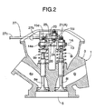
- an engine body 1 of an internal combustion engine E includes a cylinder block 2 having a cylinder bore 2a into which a piston 4 is fitted, and a cylinder head 3 joined to a top end of the cylinder block 2.
- the cylinder head 3 has a combustion chamber 5 communicating with the cylinder bore 2a, and an intake port 6i and an exhaust port 6e opening into a ceiling surface of the combustion chamber 5.
- a carburetor 7 (see FIG. 10) is connected to an upstream end of the intake port 6i.
- An exhaust muffler (not shown) is connected to a downstream end of the exhaust port 6e via an exhaust pipe.
- An intake valve 8i and an exhaust valve 8e that open and close openings of the intake port 6i and the exhaust port 6e, respectively, into the combustion chamber 5 are mounted to the cylinder head 3 with their axes in parallel.
- Valve springs 9i and 9e that urge the intake valve 8i and the exhaust valve 8e in a valve opening direction are mounted to the intake valve 8i and the exhaust valve 8e.
- the cylinder head 3 has a pair of supports 10 and 10' protruding upward.
- the supports 10 and 10' have a pair of upper support holes 11 and 11' and a pair of lower support holes 12 and 12'.
- a main rocker shaft 13 is supported by the lower support holes 12 and 12' of the supports 10 and 10'.
- An intake rocker arm 14i and an exhaust rocker arm 14e are pivotably supported by both ends of the main rocker shaft 13 protruding outward beyond the supports 10 and 10'.
- the intake rocker arm 14i is placed, with one end connected to a top end of the intake valve 8i via a gap adjustment bolt 15i and with the other end connected to a top end of an intake push rod 16i.
- the exhaust rocker arm 14e is placed, with one end connected to a top end of the exhaust valve 8e via a gap adjustment bolt 15e and with the other end connected to a top end of an exhaust push rod 16e.
- the intake push rod 16i and the exhaust push rod 16e are lifted and lowered, at their bottom ends, by an intake cam 17i; and an exhaust cam 17e, respectively, of a camshaft 17 driven in a decelerated manner from a crankshaft (not shown).
- An auxiliary rocker shaft 20 is supported by the upper support holes 11 and 11' of the supports 10 and 10'.
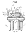
- An auxiliary rocker arm 21 placed between the supports 10 and 10' is pivotably and axially slidably supported by the auxiliary rocker shaft 20.
- a slot 22 is provided in one end of the auxiliary rocker arm 21.
- An interlock pin 23 protruding from one side of the intake rocker arm 14i in parallel with the main rocker shaft 13 is axially slidably fitted into the slot 22.
- a gap adjustment bolt 24 is threaded onto the other end of the auxiliary rocker arm 21.
- a connection piece 25 is formed on the exhaust rocker arm 14e correspondingly to the gap adjustment bolt 24.
- the auxiliary rocker arm 21 can move on the auxiliary rocker shaft 20 between a non-operating position A where the gap adjustment bolt 24 is laterally removed from above the connection piece 25, and an operating position B where the gap adjustment bolt 24 faces a top surface of the connection piece 25.
- the auxiliary rocker arm 21 that interlocks with the intake rocker arm 14i via the interlock pin 23 presses the connection piece 25 to rock the exhaust rocker arm 14e in the valve opening direction of the exhaust valve 8e.
- a direction of the slot 22 of the auxiliary rocker arm 21 that the interlock pin 23 engages is selected to reduce a rocking angle of the auxiliary rocker arm 21, and a valve opening lift of the exhaust valve 8e is set sufficiently smaller than a normal valve opening lift (see FIG. 12).
- the connection piece 25 simply moves apart from the auxiliary rocker arm 21 and is not interfered with by the auxiliary rocker arm 21.
- the auxiliary rocker arm.21 and the connection piece 25 constitute one-way connection means 26 that connects between the rocker arms 14i and 14e only when the intake rocker arm 14i rocks in the valve opening direction of the intake valve 8i.
- the shift fork 27 includes a fork 27a that clamps the auxiliary rocker arm 21 and is slidably supported on the auxiliary rocker shaft 20, a guide 27b that extends from one end of the fork 27a and slidably engages a guide groove 28 of the support 10' on the side of the exhaust rocker arm 14e, and a rod 27c that is connected to an end of the guide 27b and passes through one side wall of the cylinder head 3.
- the rod 27c is operated by a negative pressure type actuator 30.
- the negative pressure type actuator 30 includes a shell 31 mounted and secured to an appropriate position of the internal combustion engine E, a diaphragm 34 that partitions the interior of the shell 31 into an atmosphere chamber 32 and a negative pressure chamber 33, and a return spring 35 that urges the diaphragm 34 toward the non-operating position A of the auxiliary rocker arm 21 in the negative pressure chamber 33.
- An outer end of the rod 27c passing through one side wall of the shell 31 is connected to a central portion of the diaphragm 34.
- a negative pressure introduction pipe 36 leading to the negative pressure chamber 33 is formed on the other side wall of the shell 31.
- the negative pressure introduction pipe 36 is connected to a negative pressure taking-out hole 41 opening into an intake path 40 of the carburetor 7 via a negative pressure conduit 42, as shown in FIG. 10.
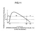
- the opening of the negative pressure taking-out hole 41 into the intake path 40 is situated upstream of a throttle valve 43 that opens and closes the intake path 40, when the throttle valve 43 occupies an idle opening degree position, and relatively moves downstream of the throttle valve 43 when the throttle valve 43 is opened to a predetermined middle opening degree or more. Therefore, a negative pressure taken out from the negative pressure taking-out hole 41 during the operation of the internal combustion engine E shows a mountain-shaped characteristic depending on increase in opening degree of the throttle valve 43, as shown in FIG. 11.
- a set load of the return spring 35 is set so that the diaphragm 34 of the actuator 30 operates when an introduced negative pressure into the negative pressure chamber 33 reaches a predetermined value P1 or more.
- reference numeral 44 denotes a main fuel nozzle opening into a venturi 40a of the intake path 40.
- the shift fork 27 holds the auxiliary rocker arm 21 at the non-operating position A by the set load of the return spring 35 in the shell 31, to remove the gap adjustment bolt 24 of the auxiliary rocker arm 21 from the connection piece 25 of the exhaust rocker arm 14e.
- the intake rocker arm 14i and the exhaust rocker arm 14e rock and cooperate with the valve springs 9i and 9e, to open and close the intake valve 8i and the exhaust valve 8e, respectively.
- rocking of the intake rocker arm 14i is transferred to the auxiliary rocker arm 21 via the interlock pin 23 to rock the auxiliary rocker arm 21, but the auxiliary rocker arm 21 holds the gap adjustment bolt 24 away from the connection piece 25 and does not interfere with the exhaust rocker arm 14e.
- the internal combustion engine E can perform intake and exhaust strokes as normal.
- the gap adjustment bolt 24 rides on the connection piece 25 of the exhaust rocker arm 14e.
- the auxiliary rocker arm 21 rocks in an interlocked manner to press down the connection piece 25 via the gap adjustment bolt 24.
- the exhaust rocker arm 14e rocks to slightly open the exhaust valve 8e.
- the exhaust valve 8e when the exhaust valve 8e is opened during the intake stroke, the exhaust gas remaining on the side of the exhaust port 6e is sucked into the combustion chamber 5, that is, the exhaust gas is refluxed.
- the exhaust gas inhibits an excessive increase in combustion temperature of the air-fuel mixture, to reduce NOx concentration in the exhaust gas.
- connection piece 25 of the exhaust rocker arm 14e moves apart from the gap adjustment bolt 24 of the auxiliary rocker arm 21, and is thus not interfered with the auxiliary rocker arm 21 and can open the exhaust valve 8e as normal.
- the actuator 30 enters the operating state, that is, an exhaust gas reflux state only when the throttle valve 43 is in the area M with the predetermined middle opening degree.
- the actuator 30 In the area L from the fully-closed position to the predetermined low opening degree of the throttle valve 43 and the area H with the predetermined high opening degree or more, the actuator 30 is not operated, and the exhaust gas is not refluxed. This allows stable combustion and reduction in fuel consumption during low speed operation including idling of the internal combustion engine E, and securing high output during high load operation.
- the exhaust valve 8e is used for the exhaust gas reflux, and thus as compared with a conventional apparatus having a special exhaust gas reflux valve, opening areas of the intake port 6i and the exhaust port 6e opening into the combustion chamber 5 can be increased, to thereby improve output performance of the internal combustion engine E. Besides, a simple configuration can be obtained since there is no increase in the number of valves, to thereby provide an inexpensive exhaust gas reflux apparatus.
- FIGS. 17 and 18 Next, a second embodiment of the invention shown in FIGS. 17 and 18 will be described.
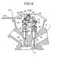
- the actuator 30 controls movement of the auxiliary rocker arm 21 from the non-operating position A to an operation start point B1 and to an operation limit point B3. Specifically, the operating position B of the auxiliary rocker arm 21 is controlled within a range from the operation start point B1 via an operation middle point B2 to the operation limit point B3.
- connection piece 25 provided on the exhaust rocker arm 14e has a slope 25a always facing a tip end of the gap adjustment bolt 24 of the auxiliary rocker arm 21 regardless of the non-operating position A, the operation start point B1, the operation middle point B2 and the operation limit point B3 of the auxiliary rocker arm 21.
- the slope 25a descends toward the non-operating position A of the auxiliary rocker arm 21.
- the slope 25a causes a gap g between the gap adjustment bolt 24 of the auxiliary rocker arm 21 and the connection piece 25 of the exhaust rocker arm 14e to increase toward the non-operating position A of the auxiliary rocker arm 21.
- the slope 25a is formed so that, when an operation stroke axially of the exhaust valve 8e of the gap adjustment bolt 24 associated with rocking of the auxiliary rocker arm 21 around the auxiliary rocker shaft 20 is S which is constant, the operation stroke S and the gap g have relationships according to the following expressions.
- the gap adjustment bolt 24 presses down the exhaust valve 8e via the connection piece 25 according to the expression g ⁇ S during the rocking of the auxiliary rocker arm 21 to provide a valve opening lift L of S - g to the exhaust valve 8e.
- the negative pressure introduced into the negative pressure chamber 33 of the actuator 30 from the carburetor 7 reaches a peak at a relatively low opening degree (when an engine load is relatively low), and then decreases with increase in opening degree (increase in load).
- the actuator 30 operates the auxiliary rocker arm 21 depending on the changes of the introduced negative pressure, and thus the valve opening lift L provided to the exhaust valve 8e by the auxiliary rocker arm 21 is high when the engine load is relatively low in the middle opening degree area M of the throttle valve 43, and then decreases with increase in engine load. Therefore, the amount of exhaust gas refluxed into the combustion chamber 5 is adjusted depending on the engine load, to thereby allow stable combustion and reduction in NOx concentration in the exhaust gas.
Landscapes
- Engineering & Computer Science (AREA)
- Mechanical Engineering (AREA)
- General Engineering & Computer Science (AREA)
- Chemical & Material Sciences (AREA)
- Combustion & Propulsion (AREA)
- Valve Device For Special Equipments (AREA)
- Exhaust-Gas Circulating Devices (AREA)
- Valve-Gear Or Valve Arrangements (AREA)
Abstract
Description
- When the
auxiliary rocker arm 21 is at the non-operating position A ... g > S - When the
auxiliary rocker arm 21 is at the operation start point B1 ... g = S - When the
auxiliary rocker arm 21 is at the operation middle point B2 ... g < S - When the
auxiliary rocker arm 21 is at the operation limit point B3 ... g = 0
Claims (5)
- An exhaust gas reflux apparatus for an internal combustion engine (E) having an intake rocker arm (14i) and an exhaust rocker arm (14e) that are pivotably supported on an engine body (1) and driven to open and close an intake valve (8i) and an exhaust valve (8e), respectively,
wherein one-way connection means (26) is provided between the intake rocker arm and the exhaust rocker arm, the one-way connection means moving between a non-operating position (A) where the intake and exhaust rocker arms are released and an operating position (B) where the intake and exhaust rocker arms are connected to open the exhaust valve only when the intake rocker arm rocks in a valve opening direction of the intake valve, and
wherein an actuator (30) for switching the one-way connection means between the non-operating position and the operating position is connected to the one-way connection means. - The exhaust gas reflux apparatus for an internal combustion engine (E) according to claim 1, wherein the actuator (30) has a negative pressure type configuration that operates when a negative pressure introduced into a negative pressure chamber (33) of the actuator reaches a predetermined value or more, and wherein the negative pressure chamber communicates with a negative pressure taking-out hole (41) opening into an intake path (40) of a carburetor (7), the negative pressure of the predetermined value or more being taken out from the intake path through the negative pressure taking-out hole in a predetermined middle opening degree area (M) of a throttle valve (43).
- The exhaust gas reflux apparatus for an internal combustion engine (E) according to claim 1 or 2, wherein the one-way connection means (26) includes an auxiliary rocker arm (21) that is pivotably supported on the engine body (1) so as to rock in an interlocked manner with the intake rocker arm (14i) and switched between a non-operating position (A) and an operating position (B) by the actuator (30), and a connection piece (25) that is provided on the exhaust rocker arm (14e) and engages the auxiliary rocker arm only when the intake rocker arm rocks in the valve opening direction of the intake valve at the operating position of the auxiliary rocker arm.
- The exhaust gas reflux apparatus for an internal combustion engine (E) according to any one of claims 1 to 3, wherein the actuator (30) is configured so that an operation stroke changes depending on an engine load, and wherein the one-way connection means (26) is configured so that a valve opening lift (L) of the exhaust valve (8e) by the one-way connection means is changed depending on the operation stroke of the actuator (30).
- The exhaust gas reflux apparatus for an internal combustion engine (E) according to claim 4, wherein the one-way connection means (26) includes an auxiliary rocker arm (21) that is pivotably supported on the engine body (1) so as to rock in an interlocked manner with the intake rocker arm (14i), the operation position of the one-way connection means being controlled from an operation start point (B1) to an operation limit point (B3) by the actuator (30), and a connection piece (25) that is provided on the exhaust rocker arm (14e) and engages the auxiliary rocker arm only when the intake rocker arm rocks in the valve opening direction of the intake valve (8i) within a range from the operation start point to the operation limit point of the auxiliary rocker arm, and wherein the connection piece is formed so that a gap (9) between the connection piece and the auxiliary rocker arm changes depending on movement of the auxiliary rocker arm from the operation start point to the operation limit point.
Applications Claiming Priority (4)
| Application Number | Priority Date | Filing Date | Title |
|---|---|---|---|
| JP2002323094 | 2002-11-06 | ||
| JP2002323094 | 2002-11-06 | ||
| JP2003347986 | 2003-10-07 | ||
| JP2003347986A JP4199086B2 (en) | 2002-11-06 | 2003-10-07 | Exhaust gas recirculation device for internal combustion engine |
Publications (3)
| Publication Number | Publication Date |
|---|---|
| EP1418314A2 true EP1418314A2 (en) | 2004-05-12 |
| EP1418314A3 EP1418314A3 (en) | 2007-04-11 |
| EP1418314B1 EP1418314B1 (en) | 2010-02-17 |
Family
ID=32109521
Family Applications (1)
| Application Number | Title | Priority Date | Filing Date |
|---|---|---|---|
| EP03257014A Expired - Lifetime EP1418314B1 (en) | 2002-11-06 | 2003-11-06 | Exhaust gas reflux apparatus for internal combustion engine |
Country Status (9)
| Country | Link |
|---|---|
| US (1) | US6892714B2 (en) |
| EP (1) | EP1418314B1 (en) |
| JP (1) | JP4199086B2 (en) |
| KR (1) | KR100585979B1 (en) |
| CN (1) | CN100339585C (en) |
| AT (1) | ATE458127T1 (en) |
| DE (1) | DE60331282D1 (en) |
| ES (1) | ES2339435T3 (en) |
| TW (1) | TWI244528B (en) |
Cited By (2)
| Publication number | Priority date | Publication date | Assignee | Title |
|---|---|---|---|---|
| WO2014090933A1 (en) * | 2012-12-12 | 2014-06-19 | Eaton Srl | A valve train assembly |
| WO2020118284A1 (en) | 2018-12-07 | 2020-06-11 | Jacobs Vehicle Systems, Inc. | Valve actuation system comprising at least two rocker arms and a one-way coupling mechanism |
Families Citing this family (11)
| Publication number | Priority date | Publication date | Assignee | Title |
|---|---|---|---|---|
| US7395790B2 (en) | 2004-11-18 | 2008-07-08 | S&S Cycle, Inc. | Reed valve breather for evolution engine |
| US7373909B2 (en) * | 2005-09-23 | 2008-05-20 | Jp Scope Llc | Valve apparatus for an internal combustion engine |
| US8528511B2 (en) | 2005-09-23 | 2013-09-10 | Jp Scope, Inc. | Variable travel valve apparatus for an internal combustion engine |
| JP4995924B2 (en) * | 2007-11-30 | 2012-08-08 | 本田技研工業株式会社 | EGR device and valve operation switching device |
| JP5145133B2 (en) | 2008-06-26 | 2013-02-13 | 本田技研工業株式会社 | General-purpose engine exhaust gas recirculation structure |
| USD610163S1 (en) | 2008-09-02 | 2010-02-16 | Wood Jeffery O | Engine |
| JP5171521B2 (en) * | 2008-09-30 | 2013-03-27 | 本田技研工業株式会社 | Variable valve gear for engine |
| USD749511S1 (en) | 2013-07-10 | 2016-02-16 | Champion Power Equipment, Inc. | Engine powered generator |
| CN104975900A (en) * | 2014-04-02 | 2015-10-14 | 陈永全 | Energy saving vehicle single cylinder engine air-stop mechanism |
| EP3309375A4 (en) * | 2015-06-15 | 2018-07-04 | Yamaha Hatsudoki Kabushiki Kaisha | Engine system and saddle ride-type vehicle |
| MX2019002668A (en) | 2016-09-09 | 2020-08-13 | Charles Price | Variable travel valve apparatus for an internal combustion engine. |
Family Cites Families (11)
| Publication number | Priority date | Publication date | Assignee | Title |
|---|---|---|---|---|
| JPS55137245A (en) | 1979-04-07 | 1980-10-25 | Unitika Ltd | Weaving of hard twisted yarn fabric by water jet loom |
| US4831915A (en) * | 1986-12-15 | 1989-05-23 | Maremont Corporation | Dual diaphragm three position actuator |
| JPS63167016A (en) * | 1986-12-27 | 1988-07-11 | Honda Motor Co Ltd | Valve train for multi-cylinder internal combustion engine |
| SE501437C2 (en) * | 1993-06-22 | 1995-02-13 | Volvo Ab | Valve mechanism in an internal combustion engine |
| JPH0893511A (en) * | 1994-09-28 | 1996-04-09 | Fuji Oozx Inc | Exhaust switching valve for internal combustion engine |
| US5960755A (en) * | 1998-06-09 | 1999-10-05 | Ford Global Technologies, Inc. | Internal combustion engine with variable camshaft timing and variable duration exhaust event |
| JP2000027654A (en) * | 1998-07-09 | 2000-01-25 | Toyota Motor Corp | Negative pressure device |
| JP2002541382A (en) * | 1999-04-14 | 2002-12-03 | ディーゼル エンジン リターダーズ,インコーポレイテッド | Exhaust and intake rocker arm assembly for correcting valve lift and valve timing during positive power |
| US6234126B1 (en) * | 1999-10-27 | 2001-05-22 | Vincent Kaye | Engine valve control |
| US6594996B2 (en) * | 2001-05-22 | 2003-07-22 | Diesel Engine Retarders, Inc | Method and system for engine braking in an internal combustion engine with exhaust pressure regulation and turbocharger control |
| US6505589B1 (en) * | 2002-02-01 | 2003-01-14 | General Motors Corporation | Single cam three-valve engine overhead valve train |
-
2003
- 2003-10-07 JP JP2003347986A patent/JP4199086B2/en not_active Expired - Fee Related
- 2003-10-29 TW TW092130089A patent/TWI244528B/en not_active IP Right Cessation
- 2003-11-04 US US10/700,051 patent/US6892714B2/en not_active Expired - Fee Related
- 2003-11-06 EP EP03257014A patent/EP1418314B1/en not_active Expired - Lifetime
- 2003-11-06 KR KR1020030078278A patent/KR100585979B1/en not_active Expired - Fee Related
- 2003-11-06 AT AT03257014T patent/ATE458127T1/en not_active IP Right Cessation
- 2003-11-06 ES ES03257014T patent/ES2339435T3/en not_active Expired - Lifetime
- 2003-11-06 DE DE60331282T patent/DE60331282D1/en not_active Expired - Lifetime
- 2003-11-06 CN CNB2003101038116A patent/CN100339585C/en not_active Expired - Fee Related
Cited By (6)
| Publication number | Priority date | Publication date | Assignee | Title |
|---|---|---|---|---|
| WO2014090933A1 (en) * | 2012-12-12 | 2014-06-19 | Eaton Srl | A valve train assembly |
| GB2522828A (en) * | 2012-12-12 | 2015-08-05 | Srl Eaton | A valve train assembly |
| GB2522828B (en) * | 2012-12-12 | 2017-06-14 | Eaton Srl | A valve train assembly |
| WO2020118284A1 (en) | 2018-12-07 | 2020-06-11 | Jacobs Vehicle Systems, Inc. | Valve actuation system comprising at least two rocker arms and a one-way coupling mechanism |
| EP3891367A4 (en) * | 2018-12-07 | 2022-09-07 | Jacobs Vehicle Systems, Inc. | VALVE ACTUATION SYSTEM INCLUDING AT LEAST TWO ROCKER ARMS AND A UNIDIRECTIONAL COUPLING MECHANISM |
| US11486274B2 (en) | 2018-12-07 | 2022-11-01 | Jacobs Vehicle Systems, Inc. | Valve actuation system comprising at least two rocker arms and a one-way coupling mechanism |
Also Published As
| Publication number | Publication date |
|---|---|
| EP1418314B1 (en) | 2010-02-17 |
| DE60331282D1 (en) | 2010-04-01 |
| US6892714B2 (en) | 2005-05-17 |
| ATE458127T1 (en) | 2010-03-15 |
| US20040154597A1 (en) | 2004-08-12 |
| CN100339585C (en) | 2007-09-26 |
| JP4199086B2 (en) | 2008-12-17 |
| CN1499069A (en) | 2004-05-26 |
| ES2339435T3 (en) | 2010-05-20 |
| EP1418314A3 (en) | 2007-04-11 |
| TWI244528B (en) | 2005-12-01 |
| TW200413635A (en) | 2004-08-01 |
| KR20040040394A (en) | 2004-05-12 |
| JP2004169687A (en) | 2004-06-17 |
| KR100585979B1 (en) | 2006-06-07 |
Similar Documents
| Publication | Publication Date | Title |
|---|---|---|
| EP1418314B1 (en) | Exhaust gas reflux apparatus for internal combustion engine | |
| EP2527630A3 (en) | Controller for an internal combustion engine with variable valve mechanism | |
| US5361734A (en) | Valve control device for an engine | |
| EP2138699B1 (en) | Exhaust gas reflux mechanism for multipurpose engine | |
| JP3983016B2 (en) | 4-stroke internal combustion engine valve deactivation mechanism | |
| JP4252670B2 (en) | Engine intake passage structure | |
| EP1273784A2 (en) | Four stroke internal combustion engine cylinder head | |
| JP2704660B2 (en) | Intake device for internal combustion engine | |
| JPS58190507A (en) | Variable driving apparatus for internal-combustion engine | |
| JPS6116219A (en) | Blow-by gas flow rate control valve for internal-combustion engine | |
| JPH0783013A (en) | Variable valve device for internal combustion engine | |
| JP3163587B2 (en) | Valve train control device for internal combustion engine | |
| JP2000328948A (en) | Engine intake control device | |
| JPS6034726Y2 (en) | Internal combustion engine intake control device | |
| JPH0629524B2 (en) | Valve timing switching device for internal combustion engine | |
| JPS6128002Y2 (en) | ||
| JPH0313560Y2 (en) | ||
| JPS6314037Y2 (en) | ||
| JPS624664Y2 (en) | ||
| JP2588362B2 (en) | Multi-cylinder internal combustion engine | |
| JPH1162564A (en) | Internal combustion engine | |
| JP2003003807A (en) | 4-stroke internal combustion engine with valve deactivation mechanism | |
| JPH021964B2 (en) | ||
| JP2001041047A (en) | Stratified scavenging two-cycle engine | |
| JPH02286870A (en) | Internal combustion engine |
Legal Events
| Date | Code | Title | Description |
|---|---|---|---|
| PUAI | Public reference made under article 153(3) epc to a published international application that has entered the european phase |
Free format text: ORIGINAL CODE: 0009012 |
|
| AK | Designated contracting states |
Kind code of ref document: A2 Designated state(s): AT BE BG CH CY CZ DE DK EE ES FI FR GB GR HU IE IT LI LU MC NL PT RO SE SI SK TR |
|
| AX | Request for extension of the european patent |
Extension state: AL LT LV MK |
|
| PUAL | Search report despatched |
Free format text: ORIGINAL CODE: 0009013 |
|
| AK | Designated contracting states |
Kind code of ref document: A3 Designated state(s): AT BE BG CH CY CZ DE DK EE ES FI FR GB GR HU IE IT LI LU MC NL PT RO SE SI SK TR |
|
| AX | Request for extension of the european patent |
Extension state: AL LT LV MK |
|
| RIC1 | Information provided on ipc code assigned before grant |
Ipc: F01L 1/46 20060101ALI20070302BHEP Ipc: F01L 1/34 20060101AFI20040220BHEP Ipc: F01L 1/14 20060101ALI20070302BHEP Ipc: F02D 13/02 20060101ALI20070302BHEP Ipc: F02M 25/07 20060101ALI20070302BHEP Ipc: F01L 13/00 20060101ALI20070302BHEP Ipc: F01L 1/18 20060101ALI20070302BHEP |
|
| 17P | Request for examination filed |
Effective date: 20071009 |
|
| AKX | Designation fees paid |
Designated state(s): AT BE BG CH CY CZ DE DK EE ES FI FR GB GR HU IE IT LI LU MC NL PT RO SE SI SK TR |
|
| 17Q | First examination report despatched |
Effective date: 20071213 |
|
| GRAP | Despatch of communication of intention to grant a patent |
Free format text: ORIGINAL CODE: EPIDOSNIGR1 |
|
| GRAS | Grant fee paid |
Free format text: ORIGINAL CODE: EPIDOSNIGR3 |
|
| GRAA | (expected) grant |
Free format text: ORIGINAL CODE: 0009210 |
|
| AK | Designated contracting states |
Kind code of ref document: B1 Designated state(s): AT BE BG CH CY CZ DE DK EE ES FI FR GB GR HU IE IT LI LU MC NL PT RO SE SI SK TR |
|
| REG | Reference to a national code |
Ref country code: GB Ref legal event code: FG4D |
|
| REG | Reference to a national code |
Ref country code: CH Ref legal event code: EP |
|
| REG | Reference to a national code |
Ref country code: IE Ref legal event code: FG4D |
|
| REF | Corresponds to: |
Ref document number: 60331282 Country of ref document: DE Date of ref document: 20100401 Kind code of ref document: P |
|
| REG | Reference to a national code |
Ref country code: ES Ref legal event code: FG2A Ref document number: 2339435 Country of ref document: ES Kind code of ref document: T3 |
|
| REG | Reference to a national code |
Ref country code: SE Ref legal event code: TRGR |
|
| REG | Reference to a national code |
Ref country code: NL Ref legal event code: VDEP Effective date: 20100217 |
|
| PG25 | Lapsed in a contracting state [announced via postgrant information from national office to epo] |
Ref country code: PT Free format text: LAPSE BECAUSE OF FAILURE TO SUBMIT A TRANSLATION OF THE DESCRIPTION OR TO PAY THE FEE WITHIN THE PRESCRIBED TIME-LIMIT Effective date: 20100617 |
|
| PG25 | Lapsed in a contracting state [announced via postgrant information from national office to epo] |
Ref country code: FI Free format text: LAPSE BECAUSE OF FAILURE TO SUBMIT A TRANSLATION OF THE DESCRIPTION OR TO PAY THE FEE WITHIN THE PRESCRIBED TIME-LIMIT Effective date: 20100217 Ref country code: AT Free format text: LAPSE BECAUSE OF FAILURE TO SUBMIT A TRANSLATION OF THE DESCRIPTION OR TO PAY THE FEE WITHIN THE PRESCRIBED TIME-LIMIT Effective date: 20100217 Ref country code: SI Free format text: LAPSE BECAUSE OF FAILURE TO SUBMIT A TRANSLATION OF THE DESCRIPTION OR TO PAY THE FEE WITHIN THE PRESCRIBED TIME-LIMIT Effective date: 20100217 |
|
| PG25 | Lapsed in a contracting state [announced via postgrant information from national office to epo] |
Ref country code: GR Free format text: LAPSE BECAUSE OF FAILURE TO SUBMIT A TRANSLATION OF THE DESCRIPTION OR TO PAY THE FEE WITHIN THE PRESCRIBED TIME-LIMIT Effective date: 20100518 Ref country code: RO Free format text: LAPSE BECAUSE OF FAILURE TO SUBMIT A TRANSLATION OF THE DESCRIPTION OR TO PAY THE FEE WITHIN THE PRESCRIBED TIME-LIMIT Effective date: 20100217 Ref country code: NL Free format text: LAPSE BECAUSE OF FAILURE TO SUBMIT A TRANSLATION OF THE DESCRIPTION OR TO PAY THE FEE WITHIN THE PRESCRIBED TIME-LIMIT Effective date: 20100217 Ref country code: EE Free format text: LAPSE BECAUSE OF FAILURE TO SUBMIT A TRANSLATION OF THE DESCRIPTION OR TO PAY THE FEE WITHIN THE PRESCRIBED TIME-LIMIT Effective date: 20100217 Ref country code: CY Free format text: LAPSE BECAUSE OF FAILURE TO SUBMIT A TRANSLATION OF THE DESCRIPTION OR TO PAY THE FEE WITHIN THE PRESCRIBED TIME-LIMIT Effective date: 20100217 |
|
| PG25 | Lapsed in a contracting state [announced via postgrant information from national office to epo] |
Ref country code: BG Free format text: LAPSE BECAUSE OF FAILURE TO SUBMIT A TRANSLATION OF THE DESCRIPTION OR TO PAY THE FEE WITHIN THE PRESCRIBED TIME-LIMIT Effective date: 20100517 Ref country code: CZ Free format text: LAPSE BECAUSE OF FAILURE TO SUBMIT A TRANSLATION OF THE DESCRIPTION OR TO PAY THE FEE WITHIN THE PRESCRIBED TIME-LIMIT Effective date: 20100217 Ref country code: SK Free format text: LAPSE BECAUSE OF FAILURE TO SUBMIT A TRANSLATION OF THE DESCRIPTION OR TO PAY THE FEE WITHIN THE PRESCRIBED TIME-LIMIT Effective date: 20100217 |
|
| PLBE | No opposition filed within time limit |
Free format text: ORIGINAL CODE: 0009261 |
|
| STAA | Information on the status of an ep patent application or granted ep patent |
Free format text: STATUS: NO OPPOSITION FILED WITHIN TIME LIMIT |
|
| 26N | No opposition filed |
Effective date: 20101118 |
|
| PG25 | Lapsed in a contracting state [announced via postgrant information from national office to epo] |
Ref country code: DK Free format text: LAPSE BECAUSE OF FAILURE TO SUBMIT A TRANSLATION OF THE DESCRIPTION OR TO PAY THE FEE WITHIN THE PRESCRIBED TIME-LIMIT Effective date: 20100217 |
|
| PG25 | Lapsed in a contracting state [announced via postgrant information from national office to epo] |
Ref country code: MC Free format text: LAPSE BECAUSE OF NON-PAYMENT OF DUE FEES Effective date: 20101130 |
|
| REG | Reference to a national code |
Ref country code: CH Ref legal event code: PL |
|
| PG25 | Lapsed in a contracting state [announced via postgrant information from national office to epo] |
Ref country code: LI Free format text: LAPSE BECAUSE OF NON-PAYMENT OF DUE FEES Effective date: 20101130 Ref country code: CH Free format text: LAPSE BECAUSE OF NON-PAYMENT OF DUE FEES Effective date: 20101130 |
|
| PG25 | Lapsed in a contracting state [announced via postgrant information from national office to epo] |
Ref country code: IE Free format text: LAPSE BECAUSE OF NON-PAYMENT OF DUE FEES Effective date: 20101106 |
|
| PG25 | Lapsed in a contracting state [announced via postgrant information from national office to epo] |
Ref country code: LU Free format text: LAPSE BECAUSE OF NON-PAYMENT OF DUE FEES Effective date: 20101106 Ref country code: HU Free format text: LAPSE BECAUSE OF FAILURE TO SUBMIT A TRANSLATION OF THE DESCRIPTION OR TO PAY THE FEE WITHIN THE PRESCRIBED TIME-LIMIT Effective date: 20100818 |
|
| PG25 | Lapsed in a contracting state [announced via postgrant information from national office to epo] |
Ref country code: TR Free format text: LAPSE BECAUSE OF FAILURE TO SUBMIT A TRANSLATION OF THE DESCRIPTION OR TO PAY THE FEE WITHIN THE PRESCRIBED TIME-LIMIT Effective date: 20100217 |
|
| PGFP | Annual fee paid to national office [announced via postgrant information from national office to epo] |
Ref country code: SE Payment date: 20141111 Year of fee payment: 12 Ref country code: FR Payment date: 20141110 Year of fee payment: 12 Ref country code: ES Payment date: 20141013 Year of fee payment: 12 Ref country code: DE Payment date: 20141029 Year of fee payment: 12 Ref country code: GB Payment date: 20141105 Year of fee payment: 12 |
|
| PGFP | Annual fee paid to national office [announced via postgrant information from national office to epo] |
Ref country code: IT Payment date: 20141112 Year of fee payment: 12 |
|
| PGFP | Annual fee paid to national office [announced via postgrant information from national office to epo] |
Ref country code: BE Payment date: 20141111 Year of fee payment: 12 |
|
| REG | Reference to a national code |
Ref country code: DE Ref legal event code: R119 Ref document number: 60331282 Country of ref document: DE |
|
| GBPC | Gb: european patent ceased through non-payment of renewal fee |
Effective date: 20151106 |
|
| PG25 | Lapsed in a contracting state [announced via postgrant information from national office to epo] |
Ref country code: IT Free format text: LAPSE BECAUSE OF NON-PAYMENT OF DUE FEES Effective date: 20151106 |
|
| REG | Reference to a national code |
Ref country code: FR Ref legal event code: ST Effective date: 20160729 |
|
| PG25 | Lapsed in a contracting state [announced via postgrant information from national office to epo] |
Ref country code: SE Free format text: LAPSE BECAUSE OF NON-PAYMENT OF DUE FEES Effective date: 20151107 |
|
| PG25 | Lapsed in a contracting state [announced via postgrant information from national office to epo] |
Ref country code: DE Free format text: LAPSE BECAUSE OF NON-PAYMENT OF DUE FEES Effective date: 20160601 Ref country code: GB Free format text: LAPSE BECAUSE OF NON-PAYMENT OF DUE FEES Effective date: 20151106 |
|
| PG25 | Lapsed in a contracting state [announced via postgrant information from national office to epo] |
Ref country code: FR Free format text: LAPSE BECAUSE OF NON-PAYMENT OF DUE FEES Effective date: 20151130 |
|
| REG | Reference to a national code |
Ref country code: ES Ref legal event code: FD2A Effective date: 20161227 |
|
| PG25 | Lapsed in a contracting state [announced via postgrant information from national office to epo] |
Ref country code: ES Free format text: LAPSE BECAUSE OF NON-PAYMENT OF DUE FEES Effective date: 20151107 |
|
| PG25 | Lapsed in a contracting state [announced via postgrant information from national office to epo] |
Ref country code: BE Free format text: LAPSE BECAUSE OF NON-PAYMENT OF DUE FEES Effective date: 20151130 |