EP1417785B1 - System and method for synchronizing telecom-related clocks in ethernet-based passive optical access network - Google Patents
System and method for synchronizing telecom-related clocks in ethernet-based passive optical access network Download PDFInfo
- Publication number
- EP1417785B1 EP1417785B1 EP02721496A EP02721496A EP1417785B1 EP 1417785 B1 EP1417785 B1 EP 1417785B1 EP 02721496 A EP02721496 A EP 02721496A EP 02721496 A EP02721496 A EP 02721496A EP 1417785 B1 EP1417785 B1 EP 1417785B1
- Authority
- EP
- European Patent Office
- Prior art keywords
- clock
- telecom
- data
- transmission
- clocks
- Prior art date
- Legal status (The legal status is an assumption and is not a legal conclusion. Google has not performed a legal analysis and makes no representation as to the accuracy of the status listed.)
- Expired - Lifetime
Links
- 238000000034 method Methods 0.000 title claims abstract description 28
- 230000003287 optical effect Effects 0.000 title claims description 28
- 230000005540 biological transmission Effects 0.000 claims abstract description 98
- 230000001360 synchronised effect Effects 0.000 claims abstract description 42
- 239000000284 extract Substances 0.000 claims description 4
- 238000012546 transfer Methods 0.000 abstract description 3
- 238000010586 diagram Methods 0.000 description 4
- 238000005516 engineering process Methods 0.000 description 3
- 230000001419 dependent effect Effects 0.000 description 2
- 239000013307 optical fiber Substances 0.000 description 2
- 230000002457 bidirectional effect Effects 0.000 description 1
- 238000012937 correction Methods 0.000 description 1
- 238000011161 development Methods 0.000 description 1
- 230000000694 effects Effects 0.000 description 1
- 238000004880 explosion Methods 0.000 description 1
- 239000000835 fiber Substances 0.000 description 1
Images



Classifications
-
- H—ELECTRICITY
- H04—ELECTRIC COMMUNICATION TECHNIQUE
- H04J—MULTIPLEX COMMUNICATION
- H04J3/00—Time-division multiplex systems
- H04J3/02—Details
- H04J3/06—Synchronising arrangements
- H04J3/0635—Clock or time synchronisation in a network
- H04J3/0638—Clock or time synchronisation among nodes; Internode synchronisation
- H04J3/0658—Clock or time synchronisation among packet nodes
- H04J3/0661—Clock or time synchronisation among packet nodes using timestamps
- H04J3/0664—Clock or time synchronisation among packet nodes using timestamps unidirectional timestamps
-
- H—ELECTRICITY
- H04—ELECTRIC COMMUNICATION TECHNIQUE
- H04J—MULTIPLEX COMMUNICATION
- H04J3/00—Time-division multiplex systems
- H04J3/02—Details
- H04J3/06—Synchronising arrangements
- H04J3/0635—Clock or time synchronisation in a network
- H04J3/0685—Clock or time synchronisation in a node; Intranode synchronisation
- H04J3/0697—Synchronisation in a packet node
-
- H—ELECTRICITY
- H04—ELECTRIC COMMUNICATION TECHNIQUE
- H04Q—SELECTING
- H04Q11/00—Selecting arrangements for multiplex systems
- H04Q11/0001—Selecting arrangements for multiplex systems using optical switching
- H04Q11/0062—Network aspects
- H04Q11/0066—Provisions for optical burst or packet networks
-
- H—ELECTRICITY
- H04—ELECTRIC COMMUNICATION TECHNIQUE
- H04Q—SELECTING
- H04Q11/00—Selecting arrangements for multiplex systems
- H04Q11/0001—Selecting arrangements for multiplex systems using optical switching
- H04Q11/0062—Network aspects
- H04Q11/0067—Provisions for optical access or distribution networks, e.g. Gigabit Ethernet Passive Optical Network (GE-PON), ATM-based Passive Optical Network (A-PON), PON-Ring
-
- H—ELECTRICITY
- H04—ELECTRIC COMMUNICATION TECHNIQUE
- H04Q—SELECTING
- H04Q11/00—Selecting arrangements for multiplex systems
- H04Q11/0001—Selecting arrangements for multiplex systems using optical switching
- H04Q11/0005—Switch and router aspects
- H04Q2011/0037—Operation
- H04Q2011/0045—Synchronisation
Definitions
- the invention relates generally to optical access networks, and more particularly to a system and method for synchronizing telecom clocks throughout a passive optical access network.
- DSL and CM technologies offer some improvements over more conventional last mile solutions. However, these technologies still do not provide enough bandwidth to support emerging services such as Video-On-Demand (VoD) or two-way video conferencing. In addition, not all customers can be covered by DSL and CM technologies due to distance limitations.
- DSL Digital Subscriber Line
- CM Cable Modem
- a point-to-multipoint PON is an optical access network architecture that facilitates broadband communications between an optical line terminal (OLT) and multiple remote optical network units (ONUs) over a purely passive optical distribution network.
- a point-to-multipoint PON utilizes passive fiber optic splitters and combiners to passively distribute optical signals between the OLT and the remote ONUs.
- EP 1 065 817 A2 discloses a method for generating a clock signal for the reverse channel of a bidirectional point-to-multipoint network.
- the method involves transmitting a central clock generated in the central station (1) over the network (2) to transmitter/receiver devices (3) in the form of digitally encoded frequency information.
- the transmitter/ receiver devices generate the clock for the return channel from the frequency information and a local clock.
- the central station provides individual phase corrections.
- Independent claims are also included for a module for generating a clock for the return channel of a bi-directional point-to-multipoint network, for a transmitter/ receiver and a central station for a network.
- EP0 977 461 A2 shows a system and method for the transmission of synchronization information from a wireless asynchronous transfer mode (ATM) base station across a point to point or point to multipoint wireless link, to one or more network interface units (NIUs).
- ATM wireless asynchronous transfer mode
- NIUs network interface units
- Each of the NIUs is capable of supporting a combination of structured or unstructured T1 and/or E1 circuit emulation services.
- the technique involves locking the wireless modem downstream symbol clock to an externally provided frequency reference from the base station.
- the reference is an N integer multiple of 8kHz which is the lowest common denominator for both the T1 and E1 clocking rates.
- Ethernet-based PONs are much more preferable than ATM-based PONs to interconnect Ethernet networks.
- IP protocol is the protocol for the internet.
- Ethernet was not originally designed to provide synchronization of telecom clocks to facilitate proper voice transmission through an Ethernet-based network. Therefore, in an Ethernet-based PON, synchronized telecom clocks may have to be independently extracted by the OLT and the ONUs from one or more external sources, such as central offices. Alternatively, a telecom clock may have to be distributed from a single source, such as the OLT, to the rest of the network, e.g., the ONUs, over a different transmission medium than the optical fibers that interconnect the OLT and the ONUs.
- these solutions significantly increase the overall cost of the PON components, as well as increase the complexity of the Ethernet-based PON.
- a system and method for synchronizing clocks related to telecommunications throughout s point-to-multipoint optical network utilizes downstream data timed using a high frequency transmission clock to distribute timing information of a central telecom-based clock to remote terminals.
- the point-to-multipoint optical network system is an Ethernet-based passive optical network (PON) system that may operate in accordance with a Gigabit Ethernet standard.
- PON passive optical network
- the timing information of the central telecom-based clock is extracted from the downstream data at each remote terminal by recovering the high frequency transmission clock and then, deriving a reference clock, which is synchronized with the central telecom-based clock, from the recovered transmission clock.
- the reference clock is then used to generate one or more telecom-related clocks that are needed by the remote terminal.
- the system and method allows telecom-related clocks throughout the system to be synchronized in an efficient and cost-effective manner.
- a method of synchronizing clocks related to telecommunications in a point-to-multipoint optical network in accordance with the present invention includes the steps of deriving a telecom-based clock at a first network terminal of the optical network from an external source, generating a data transmission clock from the telecom-based clock, transmitting data in variable-length packets from the first network terminal using the data transmission clock to embed a timing information of the telecom-based clock into the data, deriving a reference clock by extracting the timing information of the telecom-based clock from the data, and generating a remote telecom-related clock from the reference clock.
- the data transmission clock, the reference clock and the remote telecom-related clock are substantially synchronized with the telecom-based clock.
- the variable-length packets are compliant to an Ethernet-based protocol, such as a Gigabit Ethernet-based protocol.
- the method may further include the step of generating a transmission-based clock using the transmission rate of the data.
- the transmission-based clock is substantially synchronized with the data transmission clock that defined the transmission rate.
- two phase shifted transmission-based clocks are generated using the transmission rate.
- the clocks that are used by the method may be as follows: the data transmission clock may be a 125 MHz clock; the telecom-based clock and the reference clock may be 8 kHz clocks; the two phase shifted transmission-based clocks may be 62.5 MHz clocks that are phase shifted by 180 degrees to each other, and the telecom-related clock may be a 1.544 MHz clock, a 2.048 MHz clock, a 51.84 MHz clock, or any multiples thereof.
- a system in accordance with the present invention includes a central access module coupled to an external telecommunications network, and a number of remote terminals optically coupled to the central access module.
- the central access module includes a network interface that is configured to obtain a telecom-based clock from the external telecommunications network, a transmission clock generator configured to generate a data transmission clock using the telecom-based clock, and a transmitting sub-system that transmits said data in variable-length packets at a prescribed data rate, which is defined by the data transmission clock to carry timing information of the telecom-based clock with the data.
- the data transmission clock is substantially synchronized with the telecom-based clock.
- the transmitting sub-system is configured to transmit data in variable-length packets that are compliant to an Ethernet-based protocol, such as a Gigabit Ethernet-based protocol.
- Each remote terminal of the system includes a receiving sub-system that extracts the timing information of the telecom-based clock from the data and generates a reference clock, and a remote clock generator configured to generate a remote telecom-related clock from the reference clock.
- the remote telecom-related clock is substantially synchronized with the telecom-based clock at the central access module.
- the receiving sub-system of a remote terminal may include a physical layer module that generates one or more transmission-based clock from the data transmitted from the central access module, and a frequency divider operatively coupled to the physical layer module that generates the reference clock from the transmission-based clock, which is synchronized with said data transmission clock.
- the physical layer module may be configured to generate two phase shifted transmission-based clocks.
- the clocks that are used by the system may be as follows: the data transmission clock may be a 125 MHz clock; the telecom-based clock and the reference clock may be 8 kHz clocks; the two phase shifted transmission-based clocks may be 62.5 MHz clocks that are phase shifted by 180 degrees to each other; and the telecom-related clock may be a 1.544 MHz clock, a 2.048 MHz clock, a 51.84 MHz clock, or any multiples thereof.
- an Ethernet-based passive optical network (PON) system 100 in accordance with the present invention is shown.
- the PON system provides telecommunications between a central office 102 and a number of telephones 104 supported by the PON system.
- the central office and the supported telephones are connected to the PON system through conventional telecommunication lines, such as DS3 lines or T-1 lines.
- the PON system maintains synchronization of clocks related to telecommunications throughout the system in an efficient and economic manner.
- the Ethernet-based PON system 100 includes a central access module 106 that functions as a central hub for the system.
- the central access module contains a DS3 terminal (DS3T) 108, a switch 110, and a number of optical line terminals (OLTs) 112.
- the central access module is a chassis-based system that contains eight (8) OLTs.
- Each OLT of the system is connected to a number of optical network units (ONUs) 114 by optical fibers 116 and one or more splitter/combiners 118.
- ONUs optical network units
- splitter/combiners 118 As an example, each OLT may be connected to sixteen (16) ONUs.
- the PON system may support a total of one hundred twenty-eight (128) ONUs.
- the PON system uses the IEEE 802.3z protocol (commonly referred to as Gigabit Ethernet) to transmit variable-length packets of data between the OLTs and the ONUs.
- the ONUs of the system are connected, either directly or indirectly, to the telephones 104, which are supported by the PON system.
- additional telephones may be connected to each ONU.
- the number of telephones that can be connected to an ONU is dependent on the bandwidth and the number of the telecommunications lines provided by that ONU. For example, if an ONU is connected to a single T1 line, the ONU may be connected to and support up to thirty-two (32) telephones.
- the telephones may be connected to a central phone switch, such as a PBX, which is connected to the ONU.
- the telecom clocks used by the OLTs 112 for telecommunications should be synchronized with the corresponding telecom clocks used by the ONUs 114.
- a problem with providing synchronization between the OLTs and the ONUs is that the connections between the OLTs and the ONUs are based on Ethernet, and conventional Ethernet architectures are not designed to provide synchronization of telecom clocks across Ethernet connections. Therefore, the PON system 100 must resolve this problem of telecom clock synchronization in order to provide acceptable quality voice communications.
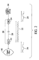
- Fig. 2 The problem of telecom clock synchronization is illustrated in Fig. 2 , which includes a simplified version 200 of the PON system 100 of Fig. 1 .
- Fig. 2 only a single OLT 212 and a single ONU 214 are shown.
- the OLT and the ONU are coupled to each other by an Ethernet connection 220.
- the OLT uses a telecom clock 216.
- the ONU uses a telecom clock 218.
- the telecom clocks 216 and 218 must be synchronized to provide proper telecommunications between the central office 102 and the telephone 104.
- any solution to the problem should efficiently and economically synchronize the telecom clock 216 at the OLT with the telecom clock 218 at the ONU.
- One prior art solution is for the OLT and the ONU to independently extract synchronized telecom clocks from one or more external sources.
- the telecom clock 216 may be derived from the central office 102, while the telecom clock 218 may be derived from a different central office (not shown).
- the telecom clock 216 may be derived from the central office 102, while the telecom clock 218 may be derived from a wireless clock source, which is synchronized with the central office.
- Another solution is for the OLT to transmit the telecom clock 216, which may be derived from the central office 102, to the ONU through a different medium than the Ethernet connection 220.
- both of these solutions require components that will significantly increase the cost for each ONU of the Ethernet-based PON system 100. Since the PON system may include up to one hundred twenty-eight (128) ONUs, even a modest increase in cost for each ONU will drastically increase the overall cost of the PON system.
- the Ethernet-based PON system 100 economically solves the problem of telecom clock synchronization by utilizing a data transmission clock 222 that is used to time the transmission of data between the OLT 212 and the ONU 214.
- a data transmission clock is independent from other clocks of the network, such as clocks related to telecommunications. Consequently, the data transmission clock 222 would not typically be synchronized with the telecom clocks 216 and 218, as illustrated in Fig. 2 . Thus, any data transmitted using the data transmission clock does not provide information to synchronize the telecom clock 218 at the ONU 214 with the telecom clock 216 at the OLT 212.
- the Ethernet-based PON system synchronizes the data transmission clock 222 with the telecom clock 216 used by the OLT to transmit the timing information of the telecom clock 216 to the ONU.
- the ONU then extracts the timing information from the transmitted data to generate the telecom clock 218, which is synchronized with the telecom clock 216 of the OLT.
- the telecom clock 218 of the ONU is synchronized with the data transmission clock 222, which in turn is synchronized with the telecom clock 216 of the OLT.
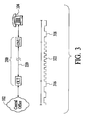
- Fig. 3 provides an illustration of a telecom clock 318 of the ONU that is synchronized with a data transmission clock 322, which in turn is synchronized with a telecom clock 316 of an ONU. As shown in Fig. 3 , the telecom clock 318 of the ONU is thus synchronized with the telecom clock 316 of the OLT.
- the OLT includes a media access control (MAC) module 402, a physical layer module 404, a Gigabit Ethernet transceiver 406, and a phase locked loop (PLL) module 408.
- the functions of these OLT components are described with respect to data transmission, since the functions are merely reversed for data reception.
- the MAC module 402 performs various data transfer functions in accordance with the Gigabit Ethernet protocol, including generating variable-length packets of data and encoding the outgoing data using 8B/10B coding, i.e., encoding 8 bits of data into 10 code bits.
- e physical layer module 404 receives the encoded data from the MAC module and serializes the data for transmission.
- the Gigabit Ethernet transceiver 406 converts the serialized bits of data, which are electrical signals, into optical signals.
- the PLL module 408 provides a data transmission clock of 125 MHz to the MAC module and the physical layer module.
- the 125 MHz data transmission clock is generated from an 8 kHz telecom-based clock, which is synchronized with the clock at the central office 102.
- the 125 MHz data transmission clock is used by the physical layer module to transmit the serialized bits of data at 1.25 Gbps in accordance with the Gigabit Ethernet protocol.
- the 8 kHz telecom-based clock used by the PLL module 408 is derived from the central office 102 through the DS3T 108 of the Ethernet-based PON system 100 shown in Fig. 1 .
- the DS3T receives a high frequency reference clock from the central office.
- the high frequency reference clock may be a 43.232 MHz clock (T3/DS3 clock).
- the DS3T then divides the high frequency reference clock to produce the 8kHz telecom-based clock, which is then distributed to the OLTs 112 by the switch 110.
- the PLL module 408 receives the 8 kHz telecom-based clock and generates the 125 MHz data transmission clock, which is synchronized with the 8 kHz telecom-based clock.
- the 125 MHz data transmission clock is then transmitted to the MAC module 402 and the physical layer module 404.
- the 125 MHz data transmission clock is used to time the transmission rate of data.
- the physical layer module multiplies the 125 MHz data transmission clock by a factor of ten, and then transmits the bits of data at a rate of 1.25 Gbps. Therefore, the transmitted data, which has been timed using the 125 MHz data transmission clock, is synchronized to the timing information of the 8 kHz telecom-based clock.
- the components of an exemplary ONU 114 are shown in Fig. 5 .
- the ONU includes a Gigabit Ethernet transceiver 502, a physical layer module 504, a MAC module 506, a frequency divider 508, and a synchronizer 510. Similar to the OLT components, the functions of the ONU components are described with respect to data reception, since the functions are merely reversed for data transmission.
- the Gigabit Ethernet transceiver 502 receives incoming bits of data in the form of optical signals and converts the optical signals to electrical signals.
- the physical layer module 504 then deserializes the converted bits of data and transmits the data bits to the MAC module 420, where the data bits are processed in accordance with the Ethernet protocol.
- the physical layer module 504 also generates two 180-degree phase-shifted 62.5 MHz transmission-based clocks, which are synchronized with the 125 MHz data transmission clock used by the OLT 112 for data transmission, from the incoming bits of data. That is, the 125 MHz data transmission clock used by the OLT is recovered from the incoming data by the physical layer module 504 in the form of two phase-shifted 62.5 MHz clocks. These phase-shifted 62.5 MHz clocks are then transmitted to the MAC module 506, where the two 62.5 MHz clocks are used to generate a 125 MHz clock, which is synchronized with the 125 MHz data transmission clock of the OLT, to process the received data.
- the phase-shifted 62.5 MHz clocks are also transmitted to the frequency divider 508 of the ONU 114.
- the frequency divider generates a reference 8 kHz telecom clock from the two phase-shifted 62.5 MHz clocks by dividing the phase-shifted clocks, in this case, by a non-integer, i.e., 7812.5. Consequently, the reference 8 kHz telecom clock is synchronized with the phase-shifted 62.5 MHz clocks.
- the frequency divider 508 generates a low frequency clock, i.e., the reference 8 kHz telecom clock, from high frequency clocks, i.e., the two 62.5 MHz clocks.
- the reference 8 kHz clock which is derived from the 62.5 MHz clocks, includes fewer errors than the 62.5 MHz clocks, which results in a more accurate clock. Since the reference 8 kHz telecom clock can be traced back to the 8 kHz telecom-based clock of the OLT 112, the reference 8 kHz telecom clock is synchronized with the 8 kHz telecom-based clock of the OLT.
- the reference 8 kHz telecom clock is used by the synchronizer 510 of the ONU 114 to generate one or more telecom clocks for telecom-related devices included in the ONU.
- the synchronizer may generate a 1.544 MHz telecom clock (T1 clock) from the reference 8 kHz telecom clock for a T1 interface module 512, as illustrated in Fig. 4 .
- the synchronizer may generate a 43.232 MHz (T3/DS3 clock), which is 28 times the T1 clock rate.
- the synchronizer may generate a 2.048 MHz clock (E1 clock) from the reference 8 kHz telecom clock for one or more E1 interface modules (not shown).
- the synchronizer may generate a 4.096 MHz telecom clock from the reference 8 kHz telecom clock for devices (not shown) related to PCM and echo cancellation.
- the synchronizer may generate a 32.768 MHz telecom clock (E3 clock), which is 16 times the E1 clock rate.
- the synchronizer may generate a 155.520 MHz clock (OC3 clock) from the reference 8 kHz telecom clock for a DS3 terminal (not shown) included in the ONU.
- the synchronizer can generate any signal that is based on an 8 kHz clock rate.
- the number and frequencies of the telecom clocks generated by the synchronizer are dependent on the various telecom-related devices that may be included in the ONU.
- these telecom-related clocks at the ONU are generated from the reference 8 kHz telecom clock, which is synchronized with the 8 kHz telecom-based clock at the OLT 112, the telecom-related clocks at the ONU are also synchronized with the 8 kHz telecom-based clock at the OLT 112.
- An advantageous feature of the Ethernet-based PON system 100 is that only a single master clock, i.e., the 8 kHz telecom-based clock, is needed to provide synchronized telecom-related clocks to all the ONUs 114 of the system.
- the master clock is derived from a single external source, i.e., the central office 102, and then distributed to the OLTs of the system. Each OLT then "distributes" the clock to the ONUs that are optically connected to that OLT.
- the telecom-related clocks at the ONUs are all derived from the single master clock.
- a telecom-based clock is derived from an external source, for example, the central office 102, at the access module 106 of the PON system.
- the telecom-based clock is derived by dividing the received clock from the external source to a lower frequency clock.
- the clock from the external source may be a 43.232 MHz clock (T3/DS3 clock).
- the telecom-based clock is an 8 kHz clock.
- the telecom-based clock is distributed to the OLTs 112 of the Ethernet-based PON system by the switch 100 of the access module.
- a data transmission clock is generated from the telecom-based clock at an OLT such that the data transmission clock is synchronized with the telecom-based clock.
- the data transmission clock is a 125 MHz clock.
- the data transmission clock is used by the MAC module 402 and the physical layer module 404 of the OLT to transmit downstream data to the ONUs that are optically connected to the OLT.
- the downstream data is optically transmitted in variable-length packets in accordance with a prescribed protocol using the data transmission clock.
- the downstream data is transmitted at a predetermined transmission rate, which is defined by the data transmission clock.
- the prescribed protocol is Gigabit Ethernet and the data transmission rate is 1.25 Gbps.
- the use of the data transmission clock, which is synchronized with the telecom-based clock, to transmit the downstream data has the effect of embedding timing information from the telecom-based clock into the data transmission clock.
- the downstream data is received at an ONU of the Ethernet-based PON system 100.
- two phase-shifted transmission-based clocks are derived from the received downstream data, which are received at the transmission rate defined by the data transmission clock of the transmitting OLT.
- the phase-shifted clocks are generated by the physical layer module 504 of the receiving ONU. Since these phase-shifted clocks are derived from the downstream data that was transmitted using the data transmission clock, the phase-shifted clocks are synchronized with the telecom-based clock at the transmitting OLT.
- the two phase-shifted clocks are two 62.5 MHz clocks, which are phase shifted by 180 degrees with respect to each other.
- an ONU reference clock is generated from the two phase-shifted clocks by the frequency divider 508 of the ONU. Since the phase-shifted clocks can be traced back to the telecom-based clock at the OLT, the ONU reference clock is synchronize with the telecom-based clock.
- one or more telecom-related clocks are generated by the synchronizer 510 of the ONU using the ONU reference clock.
- the telecom-related clocks may include a 1.544 MHz clock for a T1 interface, a 2.048 MHz clock for an E1 interface, or a 43.232 MHz clock for a DS3 interface.
- the telecom-related clocks may include a 4.096 MHz clock for devices related to PCM and echo cancellation, as well as other clocks that may be needed for telecommunications. Since these telecom-related clocks are derived from the ONU reference clock, which is synchronized with the telecom-based clock at the OLT, the telecom-related clocks at the ONU are also synchronized with the telecom-based clock at the OLT.
Landscapes
- Engineering & Computer Science (AREA)
- Computer Networks & Wireless Communication (AREA)
- Signal Processing (AREA)
- Small-Scale Networks (AREA)
- Optical Communication System (AREA)
- Synchronisation In Digital Transmission Systems (AREA)
- Time-Division Multiplex Systems (AREA)
Abstract
Description
- The invention relates generally to optical access networks, and more particularly to a system and method for synchronizing telecom clocks throughout a passive optical access network.
- The explosion of the Internet and the desire to provide multiple communications and entertainment services to end users have created a need for a broadband network architecture that improves access to end users. Although the bandwidth of backbone networks has experienced a substantial growth in recent years, the bandwidth provided by access networks has remained relatively unchanged. Thus, the "last mile" still remains a bottleneck between a high capacity LAN or Home network and the backbone network infrastructure.
- Digital Subscriber Line (DSL) and Cable Modem (CM) technologies offer some improvements over more conventional last mile solutions. However, these technologies still do not provide enough bandwidth to support emerging services such as Video-On-Demand (VoD) or two-way video conferencing. In addition, not all customers can be covered by DSL and CM technologies due to distance limitations.
- One broadband access network architecture that offers a solution to the "last mile" problem is a point-to-multipoint passive optical network (PON). A point-to-multipoint PON is an optical access network architecture that facilitates broadband communications between an optical line terminal (OLT) and multiple remote optical network units (ONUs) over a purely passive optical distribution network. A point-to-multipoint PON utilizes passive fiber optic splitters and combiners to passively distribute optical signals between the OLT and the remote ONUs.
-
EP 1 065 817 A2 -
EP0 977 461 A2 shows a system and method for the transmission of synchronization information from a wireless asynchronous transfer mode (ATM) base station across a point to point or point to multipoint wireless link, to one or more network interface units (NIUs). Each of the NIUs is capable of supporting a combination of structured or unstructured T1 and/or E1 circuit emulation services. The technique involves locking the wireless modem downstream symbol clock to an externally provided frequency reference from the base station. The reference is an N integer multiple of 8kHz which is the lowest common denominator for both the T1 and E1 clocking rates. - However, neither
EP 1 065 817 A2EP0 977 461 A2 mention to use an Ethernet protocol. - In the past, much of the PON development has been focused on ATM-based PONs. However, in recent years, there has been a growing interest in Ethernet-based PONs. This growing interest is partly due to the fact that about ninety-five percent (95%) of LANs currently use the Ethernet protocol. Therefore, Ethernet-based PONs are much more preferable than ATM-based PONs to interconnect Ethernet networks. Another contributing factor is that Ethernet is more compatible with the IP protocol, which is the protocol for the internet.
- However, unlike ATM, Ethernet was not originally designed to provide synchronization of telecom clocks to facilitate proper voice transmission through an Ethernet-based network. Therefore, in an Ethernet-based PON, synchronized telecom clocks may have to be independently extracted by the OLT and the ONUs from one or more external sources, such as central offices. Alternatively, a telecom clock may have to be distributed from a single source, such as the OLT, to the rest of the network, e.g., the ONUs, over a different transmission medium than the optical fibers that interconnect the OLT and the ONUs. However, these solutions significantly increase the overall cost of the PON components, as well as increase the complexity of the Ethernet-based PON.
- In view of the above concern, there is a need for a system and method for economically and efficiently synchronizing telecom clocks throughout an Ethernet-based PON.
- A system and method for synchronizing clocks related to telecommunications throughout s point-to-multipoint optical network utilizes downstream data timed using a high frequency transmission clock to distribute timing information of a central telecom-based clock to remote terminals. The point-to-multipoint optical network system is an Ethernet-based passive optical network (PON) system that may operate in accordance with a Gigabit Ethernet standard. The timing information of the central telecom-based clock is extracted from the downstream data at each remote terminal by recovering the high frequency transmission clock and then, deriving a reference clock, which is synchronized with the central telecom-based clock, from the recovered transmission clock. The reference clock is then used to generate one or more telecom-related clocks that are needed by the remote terminal. The system and method allows telecom-related clocks throughout the system to be synchronized in an efficient and cost-effective manner.
- A method of synchronizing clocks related to telecommunications in a point-to-multipoint optical network in accordance with the present invention includes the steps of deriving a telecom-based clock at a first network terminal of the optical network from an external source, generating a data transmission clock from the telecom-based clock, transmitting data in variable-length packets from the first network terminal using the data transmission clock to embed a timing information of the telecom-based clock into the data, deriving a reference clock by extracting the timing information of the telecom-based clock from the data, and generating a remote telecom-related clock from the reference clock. The data transmission clock, the reference clock and the remote telecom-related clock are substantially synchronized with the telecom-based clock. The variable-length packets are compliant to an Ethernet-based protocol, such as a Gigabit Ethernet-based protocol.
- The method may further include the step of generating a transmission-based clock using the transmission rate of the data. The transmission-based clock is substantially synchronized with the data transmission clock that defined the transmission rate. In an embodiment, two phase shifted transmission-based clocks are generated using the transmission rate.
- In an exemplary embodiment, the clocks that are used by the method may be as follows: the data transmission clock may be a 125 MHz clock; the telecom-based clock and the reference clock may be 8 kHz clocks; the two phase shifted transmission-based clocks may be 62.5 MHz clocks that are phase shifted by 180 degrees to each other, and the telecom-related clock may be a 1.544 MHz clock, a 2.048 MHz clock, a 51.84 MHz clock, or any multiples thereof.
- A system in accordance with the present invention includes a central access module coupled to an external telecommunications network, and a number of remote terminals optically coupled to the central access module. The central access module includes a network interface that is configured to obtain a telecom-based clock from the external telecommunications network, a transmission clock generator configured to generate a data transmission clock using the telecom-based clock, and a transmitting sub-system that transmits said data in variable-length packets at a prescribed data rate, which is defined by the data transmission clock to carry timing information of the telecom-based clock with the data. The data transmission clock is substantially synchronized with the telecom-based clock. The transmitting sub-system is configured to transmit data in variable-length packets that are compliant to an Ethernet-based protocol, such as a Gigabit Ethernet-based protocol.
- Each remote terminal of the system includes a receiving sub-system that extracts the timing information of the telecom-based clock from the data and generates a reference clock, and a remote clock generator configured to generate a remote telecom-related clock from the reference clock. The remote telecom-related clock is substantially synchronized with the telecom-based clock at the central access module.
- The receiving sub-system of a remote terminal may include a physical layer module that generates one or more transmission-based clock from the data transmitted from the central access module, and a frequency divider operatively coupled to the physical layer module that generates the reference clock from the transmission-based clock, which is synchronized with said data transmission clock. In an embodiment, the physical layer module may be configured to generate two phase shifted transmission-based clocks.
- In an exemplary embodiment, the clocks that are used by the system may be as follows: the data transmission clock may be a 125 MHz clock; the telecom-based clock and the reference clock may be 8 kHz clocks; the two phase shifted transmission-based clocks may be 62.5 MHz clocks that are phase shifted by 180 degrees to each other; and the telecom-related clock may be a 1.544 MHz clock, a 2.048 MHz clock, a 51.84 MHz clock, or any multiples thereof.
- Other aspects and advantages of the present invention will become apparent from the following detailed description, taken in conjunction with the accompanying drawings, illustrated by way of example of the principles of the invention.
-
-
Fig. 1 is a block diagram of an Ethernet-based passive optical network (PON) system in accordance with the present invention. -
Fig. 2 illustrates the problem of telecom clock synchronization across an Ethernet connection. -
Fig. 3 illustrates the use of a data transmission timing clock to resolve the problem of telecom clock synchronization across an Ethernet connection. -
Fig. 4 is a block diagram of the components of an OLT included in the Ethernet-based PON system. -
Fig. 5 is a block diagram of the components of an ONU included in the Ethernet-based PON system. -
Fig. 6 is a process flow diagram of a method of synchronizing telecom clocks in an Ethernet-based PON system in accordance with the present invention. - With reference to
Fig. 1 , an Ethernet-based passive optical network (PON)system 100 in accordance with the present invention is shown. The PON system provides telecommunications between acentral office 102 and a number oftelephones 104 supported by the PON system. The central office and the supported telephones are connected to the PON system through conventional telecommunication lines, such as DS3 lines or T-1 lines. The PON system maintains synchronization of clocks related to telecommunications throughout the system in an efficient and economic manner. - The Ethernet-based
PON system 100 includes acentral access module 106 that functions as a central hub for the system. The central access module contains a DS3 terminal (DS3T) 108, aswitch 110, and a number of optical line terminals (OLTs) 112. In an exemplary embodiment, the central access module is a chassis-based system that contains eight (8) OLTs. Each OLT of the system is connected to a number of optical network units (ONUs) 114 byoptical fibers 116 and one or more splitter/combiners 118. As an example, each OLT may be connected to sixteen (16) ONUs. Thus, the PON system may support a total of one hundred twenty-eight (128) ONUs. In an embodiment, the PON system uses the IEEE 802.3z protocol (commonly referred to as Gigabit Ethernet) to transmit variable-length packets of data between the OLTs and the ONUs. The ONUs of the system are connected, either directly or indirectly, to thetelephones 104, which are supported by the PON system. Although only a single telephone is shown to be connected to each ONU inFig. 1 , additional telephones may be connected to each ONU. The number of telephones that can be connected to an ONU is dependent on the bandwidth and the number of the telecommunications lines provided by that ONU. For example, if an ONU is connected to a single T1 line, the ONU may be connected to and support up to thirty-two (32) telephones. In an embodiment, the telephones may be connected to a central phone switch, such as a PBX, which is connected to the ONU. - In order to provide acceptable quality voice communications between the
telephones 104 and thecentral office 102, the telecom clocks used by theOLTs 112 for telecommunications should be synchronized with the corresponding telecom clocks used by theONUs 114. A problem with providing synchronization between the OLTs and the ONUs is that the connections between the OLTs and the ONUs are based on Ethernet, and conventional Ethernet architectures are not designed to provide synchronization of telecom clocks across Ethernet connections. Therefore, thePON system 100 must resolve this problem of telecom clock synchronization in order to provide acceptable quality voice communications. - The problem of telecom clock synchronization is illustrated in
Fig. 2 , which includes asimplified version 200 of thePON system 100 ofFig. 1 . InFig. 2 , only asingle OLT 212 and asingle ONU 214 are shown. The OLT and the ONU are coupled to each other by anEthernet connection 220. For telecommunications between theOLT 212 and thecentral office 102, the OLT uses atelecom clock 216. For telecommunications between theONU 214 and thetelephone 104, the ONU uses atelecom clock 218. Thus, the telecom clocks 216 and 218 must be synchronized to provide proper telecommunications between thecentral office 102 and thetelephone 104. Any solution to the problem should efficiently and economically synchronize thetelecom clock 216 at the OLT with thetelecom clock 218 at the ONU. One prior art solution is for the OLT and the ONU to independently extract synchronized telecom clocks from one or more external sources. As an example, thetelecom clock 216 may be derived from thecentral office 102, while thetelecom clock 218 may be derived from a different central office (not shown). Alternatively, thetelecom clock 216 may be derived from thecentral office 102, while thetelecom clock 218 may be derived from a wireless clock source, which is synchronized with the central office. Another solution is for the OLT to transmit thetelecom clock 216, which may be derived from thecentral office 102, to the ONU through a different medium than theEthernet connection 220. However, both of these solutions require components that will significantly increase the cost for each ONU of the Ethernet-basedPON system 100. Since the PON system may include up to one hundred twenty-eight (128) ONUs, even a modest increase in cost for each ONU will drastically increase the overall cost of the PON system. - The Ethernet-based
PON system 100 economically solves the problem of telecom clock synchronization by utilizing adata transmission clock 222 that is used to time the transmission of data between theOLT 212 and theONU 214. In conventional Ethernet architectures, a data transmission clock is independent from other clocks of the network, such as clocks related to telecommunications. Consequently, thedata transmission clock 222 would not typically be synchronized with the telecom clocks 216 and 218, as illustrated inFig. 2 . Thus, any data transmitted using the data transmission clock does not provide information to synchronize thetelecom clock 218 at theONU 214 with thetelecom clock 216 at theOLT 212. In contrast, the Ethernet-based PON system synchronizes thedata transmission clock 222 with thetelecom clock 216 used by the OLT to transmit the timing information of thetelecom clock 216 to the ONU. The ONU then extracts the timing information from the transmitted data to generate thetelecom clock 218, which is synchronized with thetelecom clock 216 of the OLT. In other words, thetelecom clock 218 of the ONU is synchronized with thedata transmission clock 222, which in turn is synchronized with thetelecom clock 216 of the OLT.Fig. 3 provides an illustration of atelecom clock 318 of the ONU that is synchronized with adata transmission clock 322, which in turn is synchronized with atelecom clock 316 of an ONU. As shown inFig. 3 , thetelecom clock 318 of the ONU is thus synchronized with thetelecom clock 316 of the OLT. - Turning to
Fig. 4 , the components of anexemplary OLT 112 of the Ethernet-basedPON system 100 are shown. The OLT includes a media access control (MAC)module 402, aphysical layer module 404, aGigabit Ethernet transceiver 406, and a phase locked loop (PLL)module 408. The functions of these OLT components are described with respect to data transmission, since the functions are merely reversed for data reception. TheMAC module 402 performs various data transfer functions in accordance with the Gigabit Ethernet protocol, including generating variable-length packets of data and encoding the outgoing data using 8B/10B coding, i.e., encoding 8 bits of data into 10 code bits. ephysical layer module 404 receives the encoded data from the MAC module and serializes the data for transmission. TheGigabit Ethernet transceiver 406 converts the serialized bits of data, which are electrical signals, into optical signals. ThePLL module 408 provides a data transmission clock of 125 MHz to the MAC module and the physical layer module. The 125 MHz data transmission clock is generated from an 8 kHz telecom-based clock, which is synchronized with the clock at thecentral office 102. The 125 MHz data transmission clock is used by the physical layer module to transmit the serialized bits of data at 1.25 Gbps in accordance with the Gigabit Ethernet protocol. - The 8 kHz telecom-based clock used by the
PLL module 408 is derived from thecentral office 102 through theDS3T 108 of the Ethernet-basedPON system 100 shown inFig. 1 . The DS3T receives a high frequency reference clock from the central office. As an example, the high frequency reference clock may be a 43.232 MHz clock (T3/DS3 clock). The DS3T then divides the high frequency reference clock to produce the 8kHz telecom-based clock, which is then distributed to theOLTs 112 by theswitch 110. At each OLT, thePLL module 408 receives the 8 kHz telecom-based clock and generates the 125 MHz data transmission clock, which is synchronized with the 8 kHz telecom-based clock. The 125 MHz data transmission clock is then transmitted to theMAC module 402 and thephysical layer module 404. At the.physical layer module, the 125 MHz data transmission clock is used to time the transmission rate of data. The physical layer module multiplies the 125 MHz data transmission clock by a factor of ten, and then transmits the bits of data at a rate of 1.25 Gbps. Therefore, the transmitted data, which has been timed using the 125 MHz data transmission clock, is synchronized to the timing information of the 8 kHz telecom-based clock. - The components of an
exemplary ONU 114 are shown inFig. 5 . The ONU includes aGigabit Ethernet transceiver 502, aphysical layer module 504, aMAC module 506, afrequency divider 508, and asynchronizer 510. Similar to the OLT components, the functions of the ONU components are described with respect to data reception, since the functions are merely reversed for data transmission. TheGigabit Ethernet transceiver 502 receives incoming bits of data in the form of optical signals and converts the optical signals to electrical signals. Thephysical layer module 504 then deserializes the converted bits of data and transmits the data bits to the MAC module 420, where the data bits are processed in accordance with the Ethernet protocol. Thephysical layer module 504 also generates two 180-degree phase-shifted 62.5 MHz transmission-based clocks, which are synchronized with the 125 MHz data transmission clock used by theOLT 112 for data transmission, from the incoming bits of data. That is, the 125 MHz data transmission clock used by the OLT is recovered from the incoming data by thephysical layer module 504 in the form of two phase-shifted 62.5 MHz clocks. These phase-shifted 62.5 MHz clocks are then transmitted to theMAC module 506, where the two 62.5 MHz clocks are used to generate a 125 MHz clock, which is synchronized with the 125 MHz data transmission clock of the OLT, to process the received data. - The phase-shifted 62.5 MHz clocks are also transmitted to the
frequency divider 508 of theONU 114. The frequency divider generates areference 8 kHz telecom clock from the two phase-shifted 62.5 MHz clocks by dividing the phase-shifted clocks, in this case, by a non-integer, i.e., 7812.5. Consequently, thereference 8 kHz telecom clock is synchronized with the phase-shifted 62.5 MHz clocks. Thus, thefrequency divider 508 generates a low frequency clock, i.e., thereference 8 kHz telecom clock, from high frequency clocks, i.e., the two 62.5 MHz clocks. The division of high frequency clocks to generate a low frequency clock reduces errors that may have been introduced into the high frequency clocks. Therefore, thereference 8 kHz clock, which is derived from the 62.5 MHz clocks, includes fewer errors than the 62.5 MHz clocks, which results in a more accurate clock. Since thereference 8 kHz telecom clock can be traced back to the 8 kHz telecom-based clock of theOLT 112, thereference 8 kHz telecom clock is synchronized with the 8 kHz telecom-based clock of the OLT. - The
reference 8 kHz telecom clock is used by thesynchronizer 510 of theONU 114 to generate one or more telecom clocks for telecom-related devices included in the ONU. In one embodiment, the synchronizer may generate a telecom clock that is a multiple of the T1 clock rate, i.e., an n×1.544 MHz clock, where n = 1, 2, 3... As an example, the synchronizer may generate a 1.544 MHz telecom clock (T1 clock) from thereference 8 kHz telecom clock for aT1 interface module 512, as illustrated inFig. 4 . As another example, the synchronizer may generate a 43.232 MHz (T3/DS3 clock), which is 28 times the T1 clock rate. In another embodiment, the synchronizer may generate a telecom clock that is a multiple of the E1 clock rate, i.e., an nx2.048 MHz clock, where n = 1, 2, 3... As an example, the synchronizer may generate a 2.048 MHz clock (E1 clock) from thereference 8 kHz telecom clock for one or more E1 interface modules (not shown). As another example, the synchronizer may generate a 4.096 MHz telecom clock from thereference 8 kHz telecom clock for devices (not shown) related to PCM and echo cancellation. As another example, the synchronizer may generate a 32.768 MHz telecom clock (E3 clock), which is 16 times the E1 clock rate. In still another embodiment, the synchronizer may generate a telecom clock that is a multiple of the OC1 clock rate, i.e., an n×51.84 MHz clock, where n = 1, 2, 3... As an example, the synchronizer may generate a 155.520 MHz clock (OC3 clock) from thereference 8 kHz telecom clock for a DS3 terminal (not shown) included in the ONU. Using thereference 8 kHz telecom clock, the synchronizer can generate any signal that is based on an 8 kHz clock rate. The number and frequencies of the telecom clocks generated by the synchronizer are dependent on the various telecom-related devices that may be included in the ONU. Since these telecom-related clocks at the ONU are generated from thereference 8 kHz telecom clock, which is synchronized with the 8 kHz telecom-based clock at theOLT 112, the telecom-related clocks at the ONU are also synchronized with the 8 kHz telecom-based clock at theOLT 112. - An advantageous feature of the Ethernet-based
PON system 100 is that only a single master clock, i.e., the 8 kHz telecom-based clock, is needed to provide synchronized telecom-related clocks to all theONUs 114 of the system. The master clock is derived from a single external source, i.e., thecentral office 102, and then distributed to the OLTs of the system. Each OLT then "distributes" the clock to the ONUs that are optically connected to that OLT. Thus, the telecom-related clocks at the ONUs are all derived from the single master clock. - A method of synchronizing telecom clocks throughout the Ethernet-based
PON system 100 in accordance with the present invention is described with reference toFig. 6 . Atstep 602, a telecom-based clock is derived from an external source, for example, thecentral office 102, at theaccess module 106 of the PON system. The telecom-based clock is derived by dividing the received clock from the external source to a lower frequency clock. As an example, the clock from the external source may be a 43.232 MHz clock (T3/DS3 clock).. In an exemplary embodiment, the telecom-based clock is an 8 kHz clock. Atstep 604, the telecom-based clock is distributed to theOLTs 112 of the Ethernet-based PON system by theswitch 100 of the access module. Next, atstep 606, a data transmission clock is generated from the telecom-based clock at an OLT such that the data transmission clock is synchronized with the telecom-based clock. In the exemplary embodiment, the data transmission clock is a 125 MHz clock. The data transmission clock is used by theMAC module 402 and thephysical layer module 404 of the OLT to transmit downstream data to the ONUs that are optically connected to the OLT. - Next, at
step 608, the downstream data is optically transmitted in variable-length packets in accordance with a prescribed protocol using the data transmission clock. The downstream data is transmitted at a predetermined transmission rate, which is defined by the data transmission clock. In the exemplary embodiment, the prescribed protocol is Gigabit Ethernet and the data transmission rate is 1.25 Gbps. The use of the data transmission clock, which is synchronized with the telecom-based clock, to transmit the downstream data has the effect of embedding timing information from the telecom-based clock into the data transmission clock. At step 610, the downstream data is received at an ONU of the Ethernet-basedPON system 100. Next, atstep 612, two phase-shifted transmission-based clocks are derived from the received downstream data, which are received at the transmission rate defined by the data transmission clock of the transmitting OLT. The phase-shifted clocks are generated by thephysical layer module 504 of the receiving ONU. Since these phase-shifted clocks are derived from the downstream data that was transmitted using the data transmission clock, the phase-shifted clocks are synchronized with the telecom-based clock at the transmitting OLT. In the exemplary embodiment, the two phase-shifted clocks are two 62.5 MHz clocks, which are phase shifted by 180 degrees with respect to each other. - Next, at
step 614, an ONU reference clock is generated from the two phase-shifted clocks by thefrequency divider 508 of the ONU. Since the phase-shifted clocks can be traced back to the telecom-based clock at the OLT, the ONU reference clock is synchronize with the telecom-based clock. Atstep 616, one or more telecom-related clocks are generated by thesynchronizer 510 of the ONU using the ONU reference clock. The telecom-related clocks may include a 1.544 MHz clock for a T1 interface, a 2.048 MHz clock for an E1 interface, or a 43.232 MHz clock for a DS3 interface. In addition, the telecom-related clocks may include a 4.096 MHz clock for devices related to PCM and echo cancellation, as well as other clocks that may be needed for telecommunications. Since these telecom-related clocks are derived from the ONU reference clock, which is synchronized with the telecom-based clock at the OLT, the telecom-related clocks at the ONU are also synchronized with the telecom-based clock at the OLT.
Claims (17)
- A method of distributing a telecom-based master clock in an Ethernet-based point-to-multipoint optical network (100) comprising:deriving said telecom-based master clock at a central terminal (106) of said point-to-multipoint optical network (100) from an external source, which is external to the point-to-multipoint optical network (102);generating a data transmission clock that is synchronized with said telecom-based master clock, said data transmission clock being a higher frequency clock than said telecom-based master clock; andtransmitting data in variable-length packets from said central terminal (106) to remote terminals (114), said data being transmitted at a transmission rate defined by said data transmission clock to carry timing information of said telecom-based master clock to said remote terminals (114) and said variable length packets are compliant to an Ethernet-based protocol.
- The method of claim 1 wherein said step of transmitting said data in said variable-length packets includes transmitting said data in said variable length packets that are compliant to a Gigabit Ethernet-based protocol.
- The method of claim 1 wherein said step of deriving said telecom-based master clock includes dividing a telecom-related clock from said external source to derive said telecom-based master clock, said telecom-based master clock being an 8 kHz clock.
- The method of claim 3 wherein said step of generating said data transmission clock includes generating a 125 MHz clock using said 8 kHz clock.
- The method of anyone of claims 1 to 4 comprising:receiving said data in variable-length packets at a remote terminal (114) of said point-to-multipoint optical network (100), said variable-length packets are compliant to an Ethernet-based protocol;deriving a reference clock by extracting timing information of said data transmission clock from said data, said reference clock being synchronized with said data transmission clock; andgenerating a telecom-related clock from said reference clock, said telecom-related clock being synchronized with said telecom-based master clock.
- The method of claim 5 wherein said step of receiving said data in said variable-length packets includes receiving said data in said variable-length packets that are compliant to a Gigabit Ethernet-based protocol.
- The method of claim 5 further comprising a step of generating a transmission-based clock using said transmission rate of said data, said transmission-based clock being synchronized with said data transmission clock that defined said transmission rate, and a step of generating said reference clock from said transmission based clock.
- The method of claim 7 wherein said step of generating said transmission-based clock includes generating two transmission-based clocks that are phase shifted.
- The method of claim 8 wherein said two transmission-based clocks are two 62.5 MHz clocks that are phase shifted by 180 degrees to each other, and wherein said data transmission clock is a 125 MHz clock.
- The method of claim 5 wherein said telecom-based master clock and said reference clock are 8 kHz clocks.
- The method of claim 5 wherein said step of generating said telecom-related clock from said reference clock includes generating said telecom-related clock selected from a group consisting of a 1.544 MHz clock, a 2.048 MHz clock, a 51.84 MHz clock, and multiples thereof.
- An Ethernet-based point-to-multipoint optical network system (100) comprising:a central access module (106) coupled to an external telecommunications network, which is external to the point-to-multipoint optical network system, said central access module (106) comprising:a network interface that receives data from said external telecommunications network, said network interface (112) configured to obtain a telecom-based clock from said external telecommunications network;a transmission clock generator (408) configured to generate a data transmission clock using said telecom-based clock, said data transmission clock being synchronized with said telecom-based clock; anda transmitting sub-system (406) that transmits said data in variable-length packets at a prescribed data rate, said prescribed data rate being defined by said data transmission clock to carry timing information of said telecom-based clock with said data and said variable length packets are compliant to an Ethernet-based protocol; andsaid Ethernet-based point-to-multipoint optical network system further comprising:a plurality of remote terminals (114) optically coupled to said central access module (106) to receive said data, each remote terminal (114) comprising:a receiving sub-system (502) that extracts said timing information of said telecom-based clock from said data and generates a reference clock; anda remote clock generator configured to generate a remote telecom-related clock from said reference clock, said remote telecom-related clock being synchronized with said telecom-based clock at said central access module.
- The system of claim 12 wherein said transmitting sub-system (406) of said central access module (106) is configured to transmit said data in said variable length packets that are compliant to a Gigabit Ethernet-based protocol.
- The system of claim 12 wherein said receiving sub-system (502) includes:a physical layer module (504) that generates a transmission-based clock from said data, said transmission-based clock being synchronized with said data transmission clock; anda frequency divider (508) operatively coupled to said physical layer module (504) that generates said reference clock from said transmission-based clock.
- The system of claim 14 wherein said physical layer module (504) generates two transmission-based clocks, said two transmission-based clocks being 62.5 MHz clocks that are phase shifted by 180 degrees.
- The system of claim 12 wherein said telecom-based clock and said reference clock are 8 kHz clocks.
- The system of claim 12 wherein said remote clock generator is configured to generate said remote telecom-related clock selected from a group consisting of a 1.544 MHz clock, a 2.048 MHz clock, a 51.84 MHz clock, and multiples thereof.
Applications Claiming Priority (3)
| Application Number | Priority Date | Filing Date | Title |
|---|---|---|---|
| US09/813,774 US6470032B2 (en) | 2001-03-20 | 2001-03-20 | System and method for synchronizing telecom-related clocks in ethernet-based passive optical access network |
| PCT/US2002/008553 WO2002075969A1 (en) | 2001-03-20 | 2002-03-20 | System and method for synchronizing telecom-related clocks in ethernet-based passive optical access network |
| US813774 | 2004-03-31 |
Publications (3)
| Publication Number | Publication Date |
|---|---|
| EP1417785A1 EP1417785A1 (en) | 2004-05-12 |
| EP1417785A4 EP1417785A4 (en) | 2005-10-19 |
| EP1417785B1 true EP1417785B1 (en) | 2009-11-11 |
Family
ID=25213345
Family Applications (1)
| Application Number | Title | Priority Date | Filing Date |
|---|---|---|---|
| EP02721496A Expired - Lifetime EP1417785B1 (en) | 2001-03-20 | 2002-03-20 | System and method for synchronizing telecom-related clocks in ethernet-based passive optical access network |
Country Status (7)
| Country | Link |
|---|---|
| US (2) | US6470032B2 (en) |
| EP (1) | EP1417785B1 (en) |
| AT (1) | ATE448611T1 (en) |
| DE (1) | DE60234349D1 (en) |
| ES (1) | ES2335868T3 (en) |
| TW (1) | TWI226769B (en) |
| WO (1) | WO2002075969A1 (en) |
Families Citing this family (68)
| Publication number | Priority date | Publication date | Assignee | Title |
|---|---|---|---|---|
| US6870836B1 (en) * | 2000-03-31 | 2005-03-22 | Nortel Networks Limited | System and method for transfer of IP data in an optical communication networks |
| US7228077B2 (en) * | 2000-05-12 | 2007-06-05 | Forster Energy Llc | Channel gain control for an optical communications system utilizing frequency division multiplexing |
| US6700903B1 (en) * | 2000-05-22 | 2004-03-02 | Terawave Communications, Inc. | Upstream scrambler seeding system and method in a passive optical network |
| US7028204B2 (en) * | 2000-09-06 | 2006-04-11 | Schneider Automation Inc. | Method and apparatus for ethernet prioritized device clock synchronization |
| US6572293B1 (en) * | 2000-09-14 | 2003-06-03 | Electronics For Imaging, Inc. | Simple and inexpensive high-capacity output catch tray for document production machines |
| US20020110157A1 (en) * | 2001-02-14 | 2002-08-15 | Kestrel Solutions | Method and apparatus for providing a gigabit ethernet circuit pack |
| US6470032B2 (en) * | 2001-03-20 | 2002-10-22 | Alloptic, Inc. | System and method for synchronizing telecom-related clocks in ethernet-based passive optical access network |
| EP1271825A1 (en) * | 2001-06-25 | 2003-01-02 | Lucent Technologies Inc. | Method and system for multiplexed optical information transport |
| FI111898B (en) * | 2001-08-17 | 2003-09-30 | Heikki Tapio Laamanen | Method of establishing a subscriber connection and system applying the method |
| US20030048501A1 (en) * | 2001-09-12 | 2003-03-13 | Michael Guess | Metropolitan area local access service system |
| US20030093703A1 (en) * | 2001-11-09 | 2003-05-15 | Adc Dsl Systems, Inc. | Multiple dataport clock synchronization |
| JP4491771B2 (en) * | 2001-11-29 | 2010-06-30 | 日本ビクター株式会社 | Optical transmission / reception system |
| KR100421151B1 (en) * | 2002-01-17 | 2004-03-04 | 삼성전자주식회사 | Method for implementation procedure in giga bit ethernet passive optical network and ethernet frame structure thereof |
| KR100419425B1 (en) * | 2002-02-01 | 2004-02-21 | 삼성전자주식회사 | Circuit for controlling output of idle pattern in gigabit ethernet - passive optical network |
| GB2385684A (en) * | 2002-02-22 | 2003-08-27 | Sony Uk Ltd | Frequency synchronisation of clocks |
| US7483450B1 (en) * | 2002-03-08 | 2009-01-27 | Nortel Networks Limited | Method and system for link-based clock synchronization in asynchronous networks |
| US7206516B2 (en) * | 2002-04-30 | 2007-04-17 | Pivotal Decisions Llc | Apparatus and method for measuring the dispersion of a fiber span |
| US6816018B1 (en) | 2002-07-19 | 2004-11-09 | 3Com Corporation | System and method for partitioning a system timing reference among multiple circuit boards |
| GB2392353B (en) * | 2002-08-21 | 2005-11-02 | Zarlink Semiconductor Ltd | Method and apparatus for distributing timing data across a packet network |
| US7079554B2 (en) * | 2002-10-16 | 2006-07-18 | Terasync, Ltd. | System and method for synchronizing between communication terminals of asynchronous packets networks |
| US7248802B2 (en) * | 2002-11-27 | 2007-07-24 | Nokia Corporation | Distribution of a synchronization signal in an optical communication system |
| US7804852B1 (en) * | 2003-01-24 | 2010-09-28 | Douglas Durham | Systems and methods for definition and use of a common time base in multi-protocol environments |
| US7844690B1 (en) | 2003-01-24 | 2010-11-30 | Douglas Durham | Systems and methods for creation and use of a virtual protocol analyzer |
| EP1595347A1 (en) * | 2003-02-20 | 2005-11-16 | Zarlink Semiconductor Inc. | Method providing distribution means for reference clocks across packetized networks |
| GB2399263A (en) | 2003-03-07 | 2004-09-08 | Zarlink Semiconductor Ltd | Clock synchronisation over a packet network |
| US9337948B2 (en) | 2003-06-10 | 2016-05-10 | Alexander I. Soto | System and method for performing high-speed communications over fiber optical networks |
| US20040264961A1 (en) * | 2003-06-12 | 2004-12-30 | Nam Hong Soon | Ethernet passive optical network system, and optical network terminal and optical line terminal provided in the same |
| US7409154B2 (en) * | 2003-08-05 | 2008-08-05 | Lucent Technologies Inc. | System and method for a protected optical access ring network |
| US7920601B2 (en) * | 2003-12-19 | 2011-04-05 | Gentex Corporation | Vehicular communications system having improved serial communication |
| US7103073B2 (en) * | 2004-02-19 | 2006-09-05 | Advanced Fibre Communications, Inc. | Optical line termination, passive optical network, and method and apparatus for performance monitoring |
| US20080247550A1 (en) * | 2004-05-14 | 2008-10-09 | Seiji Kozaki | Pon System with Encryption Function and Encryption Method of Pon System |
| US20060018322A1 (en) * | 2004-07-21 | 2006-01-26 | Moshe Oron | Dedicated service class for voice traffic |
| GB2417867B (en) * | 2004-09-03 | 2007-04-11 | Sony Uk Ltd | Data transmission |
| CN100370795C (en) * | 2004-09-09 | 2008-02-20 | 烽火通信科技股份有限公司 | Method for implementing pseudo loop-back clock of optical network unit in Ethernet passive optical network system |
| US8625547B1 (en) | 2005-03-11 | 2014-01-07 | At&T Intellectual Property Ii, L.P. | Two-tier wireless broadband access network |
| KR101242461B1 (en) | 2005-06-29 | 2013-03-12 | 테크노버스, 인크. | Accomodating Different Clock Frequencies In An Ethernet Passive Optical Network |
| CN100542083C (en) * | 2005-08-24 | 2009-09-16 | 华为技术有限公司 | Method and system for realizing network synchronization through packet network |
| CN1866803B (en) * | 2005-09-13 | 2012-05-30 | 华为技术有限公司 | Method for solving clock synchronization in total Ethernet |
| CN100589433C (en) * | 2005-10-25 | 2010-02-10 | 华为技术有限公司 | Method and system for providing clock synchronization over a packet network |
| DE602005024158D1 (en) * | 2005-12-19 | 2010-11-25 | Alcatel Lucent | A method of passing a constant bit rate signal over an Ethernet port and system for performing the method |
| CN101009584B (en) * | 2006-01-24 | 2011-04-20 | 华为技术有限公司 | Method, device and system for speed upgrade of the passive optical network |
| US7660330B1 (en) * | 2006-06-28 | 2010-02-09 | Atrica Israel Ltd. | Clock synchronization and distribution over an optical Ethernet network |
| US7649910B1 (en) | 2006-07-13 | 2010-01-19 | Atrica Israel Ltd. | Clock synchronization and distribution over a legacy optical Ethernet network |
| US9178713B1 (en) | 2006-11-28 | 2015-11-03 | Marvell International Ltd. | Optical line termination in a passive optical network |
| US8208815B1 (en) * | 2006-11-30 | 2012-06-26 | Marvell International Ltd. | Bit accurate upstream burst transmission phase method for reducing burst data arrival variation |
| WO2008072356A1 (en) * | 2006-12-15 | 2008-06-19 | Fujitsu Limited | Optical communication system, its optical communication method, and communication device |
| DE102006060821A1 (en) * | 2006-12-21 | 2008-06-26 | Infineon Technologies Ag | Network synchronous data interface |
| US7835644B2 (en) * | 2006-12-22 | 2010-11-16 | Verizon Patent And Licensing Inc. | System for intercepting signals to be transmitted over a fiber optic network and associated method |
| US7660333B2 (en) * | 2007-03-12 | 2010-02-09 | Tellabs Petaluma, Inc. | Method and apparatus for detecting and compensating for jitter in a communications network |
| JP2008301153A (en) * | 2007-05-31 | 2008-12-11 | Oki Electric Ind Co Ltd | Passive optical network communication method and system |
| US8401387B2 (en) * | 2007-08-30 | 2013-03-19 | Calix, Inc. | Optical network interface devices and methods |
| JP5188170B2 (en) * | 2007-12-21 | 2013-04-24 | 株式会社日立製作所 | Network system and OLT |
| US7864747B2 (en) * | 2008-03-28 | 2011-01-04 | Embarq Holdings Company, Llc | System and method for communicating timing to a remote node |
| CN101577600B (en) * | 2008-05-09 | 2013-04-24 | 华为技术有限公司 | Time synchronization method, system and optical network equipment for passive optical network system |
| CN101631014B (en) * | 2008-07-14 | 2012-04-04 | 华为技术有限公司 | Method, device and system for transmitting synchronous clock |
| CN101707505B (en) * | 2008-08-13 | 2013-08-28 | 华为技术有限公司 | Method and device for time synchronization in passive optical network and passive optical network |
| CN101729180A (en) * | 2008-10-21 | 2010-06-09 | 华为技术有限公司 | Method and system for synchronizing precision clocks, and precision clock frequency/time synchronizing device |
| US8942561B2 (en) * | 2008-10-21 | 2015-01-27 | Broadcom Corporation | Synchronization transport over passive optical networks |
| US9425983B2 (en) | 2009-01-16 | 2016-08-23 | Telefonaktiebolaget Lm Ericsson (Publ) | Method and an interconnecting node for use in an access network |
| CN101795423A (en) * | 2009-02-04 | 2010-08-04 | 中兴通讯股份有限公司 | Method and system for synchronizing time of passive optical network |
| US8335235B2 (en) * | 2009-03-20 | 2012-12-18 | Broadcom Corporation | Methods and apparatus for extending MAC control message in EPON |
| CN102136900B (en) * | 2010-01-22 | 2014-11-05 | 华为技术有限公司 | Time synchronization method for passive optical network, device and system |
| US9252904B2 (en) * | 2011-06-01 | 2016-02-02 | Coriant Operations, Inc. | Method and apparatus for distributing network timing in a mesh optical network |
| CN102264012B (en) * | 2011-07-29 | 2017-11-28 | 中兴通讯股份有限公司 | The local oscillator synchronous method and ONU and OLT of a kind of PON system |
| US9762434B2 (en) * | 2011-08-12 | 2017-09-12 | Rambus Inc. | Temporal redundancy |
| EP3185487B1 (en) * | 2014-08-22 | 2018-12-12 | Nippon Telegraph And Telephone Corporation | Station-side device in optical transmission system, optical transmission system and optical transmission method |
| CN104539438B (en) * | 2015-01-07 | 2018-04-17 | 烽火通信科技股份有限公司 | A kind of system and method for being used in PON system realize multicast service layering |
| WO2018161282A1 (en) * | 2017-03-08 | 2018-09-13 | 华为技术有限公司 | Clock synchronization method and apparatus and passive optical network system |
Family Cites Families (20)
| Publication number | Priority date | Publication date | Assignee | Title |
|---|---|---|---|---|
| US5260978A (en) | 1992-10-30 | 1993-11-09 | Bell Communications Research, Inc. | Synchronous residual time stamp for timing recovery in a broadband network |
| DE59408360D1 (en) | 1994-03-15 | 1999-07-08 | Siemens Ag | Method for receiving clock supply for video signals transmitted digitally by means of ATM in fiber / coaxial subscriber access networks |
| JP3386221B2 (en) * | 1994-03-17 | 2003-03-17 | 富士通株式会社 | Clock transfer circuit for asynchronous data |
| IT1270046B (en) * | 1994-04-21 | 1997-04-28 | Italtel Spa | METHOD AND DEVICE FOR TIMING THE TRANSMISSION OF DIGITAL SIGNALS INTO A TDMA PON SYSTEM |
| US5796795A (en) * | 1994-11-30 | 1998-08-18 | Gte Laboratories Incorporated | Data transferring circuit which aligns clock and data |
| CA2224605C (en) * | 1995-06-27 | 2002-10-22 | British Telecommunications Public Limited Company | Synchronisation in digital communications networks |
| DE19620723A1 (en) * | 1996-05-23 | 1997-11-27 | Sel Alcatel Ag | Optical network unit and headquarters of an optical communication network |
| US6044122A (en) | 1997-01-23 | 2000-03-28 | Ericsson, Inc. | Digital phase acquisition with delay locked loop |
| US6038226A (en) | 1997-03-31 | 2000-03-14 | Ericcson Inc. | Combined signalling and PCM cross-connect and packet engine |
| US5978374A (en) | 1997-04-03 | 1999-11-02 | Ericsson, Inc. | Protocol for data communication over a point-to-multipoint passive optical network |
| US6070248A (en) * | 1997-12-12 | 2000-05-30 | Advanced Micro Devices, Inc. | Generation of a stable reference clock frequency from a base clock frequency that may vary depending on source |
| CA2243888C (en) * | 1998-07-27 | 2005-10-18 | Newbridge Networks Corporation | Ds-o synchronization over a wireless atm link |
| US6665316B1 (en) * | 1998-09-29 | 2003-12-16 | Agilent Technologies, Inc. | Organization of time synchronization in a distributed system |
| GB2349315B (en) * | 1999-04-16 | 2003-06-04 | Fujitsu Ltd | Delay adjustment unit and method, optical network unit, and communication system |
| DE19929337C2 (en) * | 1999-06-26 | 2002-04-25 | Alcatel Sa | Method for generating a clock for the return channel of a bidirectional point-to-multipoint network |
| DE60035116T2 (en) * | 1999-09-03 | 2008-02-07 | Broadcom Corp., Irvine | SYSTEM AND METHOD FOR SYNCHRONIZING AND DISTRIBUTING TELEPHONE CONTACT INFORMATION IN A CABLE MODEM NETWORK |
| US20030012158A1 (en) * | 2001-01-25 | 2003-01-16 | Hang Jin | System and method for synchronizing a base station in a distributed radio system |
| US7301968B2 (en) * | 2001-03-02 | 2007-11-27 | Pmc-Sierra Israel Ltd. | Communication protocol for passive optical network topologies |
| US6470032B2 (en) * | 2001-03-20 | 2002-10-22 | Alloptic, Inc. | System and method for synchronizing telecom-related clocks in ethernet-based passive optical access network |
| WO2003017545A1 (en) * | 2001-08-21 | 2003-02-27 | Broadcom Corporation | System, method, and computer program product for ethernet-passive optical networks |
-
2001
- 2001-03-20 US US09/813,774 patent/US6470032B2/en not_active Expired - Lifetime
-
2002
- 2002-03-18 TW TW091105034A patent/TWI226769B/en not_active IP Right Cessation
- 2002-03-20 ES ES02721496T patent/ES2335868T3/en not_active Expired - Lifetime
- 2002-03-20 DE DE60234349T patent/DE60234349D1/en not_active Expired - Lifetime
- 2002-03-20 EP EP02721496A patent/EP1417785B1/en not_active Expired - Lifetime
- 2002-03-20 AT AT02721496T patent/ATE448611T1/en not_active IP Right Cessation
- 2002-03-20 WO PCT/US2002/008553 patent/WO2002075969A1/en not_active Ceased
- 2002-10-18 US US10/273,536 patent/US7555015B2/en not_active Expired - Lifetime
Also Published As
| Publication number | Publication date |
|---|---|
| US6470032B2 (en) | 2002-10-22 |
| ES2335868T3 (en) | 2010-04-06 |
| US20030039272A1 (en) | 2003-02-27 |
| TWI226769B (en) | 2005-01-11 |
| US20020136232A1 (en) | 2002-09-26 |
| ATE448611T1 (en) | 2009-11-15 |
| WO2002075969A1 (en) | 2002-09-26 |
| DE60234349D1 (en) | 2009-12-24 |
| EP1417785A1 (en) | 2004-05-12 |
| EP1417785A4 (en) | 2005-10-19 |
| US7555015B2 (en) | 2009-06-30 |
Similar Documents
| Publication | Publication Date | Title |
|---|---|---|
| US6470032B2 (en) | System and method for synchronizing telecom-related clocks in ethernet-based passive optical access network | |
| US5543951A (en) | Method for receive-side clock supply for video signals digitally transmitted with ATM in fiber/coaxial subscriber line networks | |
| US8712243B2 (en) | Methods and apparatus for achieving multiple bit rates in passive optical networks | |
| CA2186800C (en) | Method and apparatus for converting synchronous narrowband signals into a sonet virtual tributary group for combining with broadband asynchronous transfer mode signals in an integrated telecommunications network | |
| US20040264961A1 (en) | Ethernet passive optical network system, and optical network terminal and optical line terminal provided in the same | |
| US9100130B2 (en) | Burst mode to continuous mode converter | |
| WO1997049210A1 (en) | Synchronous plesiochronous digital hierarchy transmission systems | |
| CA2332387A1 (en) | Method and apparatus for tdm/tdma communications | |
| WO2007011455A2 (en) | Method and apparatus for facilitating asymmetric line rates in an ethernet passive optical network | |
| EP1342106A2 (en) | Point-to-multipoint passive optical network that utilizes variable-length packets and variable-length upstream tine slots | |
| US20040246989A1 (en) | SONET over PON | |
| US6792101B2 (en) | Method to transport a reference clock signal | |
| KR100704111B1 (en) | Data processing device and method for transmission convergence layer function in passive optical branch network | |
| JP2006067354A (en) | PON system and TDM signal transmission method | |
| Du Chaffaut et al. | A flexible ATM PON system for the local loop | |
| KR100362174B1 (en) | Apparatus for PON Interface and Service multiplexing in ATM-PON pole ONU | |
| Keller et al. | Optical broadband access using ATM on a passive optical network | |
| KR20010063842A (en) | Apparatus For Master Matching Of Passive Optical Network | |
| US20100166021A1 (en) | Subscriber line interface circuitry with integrated serial interfaces | |
| US20100166019A1 (en) | Subscriber line interface circuitry with integrated serial interfaces | |
| Wu et al. | Implementation of Flexible Access System | |
| US20100166434A1 (en) | Subscriber line interface circuitry with integrated serial interfaces | |
| Reynolds | Wireline Access Networks | |
| WO2010078474A2 (en) | Subscriber line interface circuitry with integrated serial interfaces | |
| KR20040060277A (en) | Apparatus for transmitting framer in asynchronous transfer mode based passive optical network |
Legal Events
| Date | Code | Title | Description |
|---|---|---|---|
| PUAI | Public reference made under article 153(3) epc to a published international application that has entered the european phase |
Free format text: ORIGINAL CODE: 0009012 |
|
| 17P | Request for examination filed |
Effective date: 20040206 |
|
| AK | Designated contracting states |
Kind code of ref document: A1 Designated state(s): AT BE CH CY DE DK ES FI FR GB GR IE IT LI LU MC NL PT SE TR |
|
| A4 | Supplementary search report drawn up and despatched |
Effective date: 20050906 |
|
| RIC1 | Information provided on ipc code assigned before grant |
Ipc: 7H 04J 3/00 A |
|
| 17Q | First examination report despatched |
Effective date: 20071023 |
|
| GRAP | Despatch of communication of intention to grant a patent |
Free format text: ORIGINAL CODE: EPIDOSNIGR1 |
|
| RAP1 | Party data changed (applicant data changed or rights of an application transferred) |
Owner name: HUAWEI TECHNOLOGIES CO., LTD. |
|
| GRAS | Grant fee paid |
Free format text: ORIGINAL CODE: EPIDOSNIGR3 |
|
| GRAA | (expected) grant |
Free format text: ORIGINAL CODE: 0009210 |
|
| AK | Designated contracting states |
Kind code of ref document: B1 Designated state(s): AT BE CH CY DE DK ES FI FR GB GR IE IT LI LU MC NL PT SE TR |
|
| REG | Reference to a national code |
Ref country code: GB Ref legal event code: FG4D |
|
| REG | Reference to a national code |
Ref country code: CH Ref legal event code: EP |
|
| REG | Reference to a national code |
Ref country code: IE Ref legal event code: FG4D |
|
| REF | Corresponds to: |
Ref document number: 60234349 Country of ref document: DE Date of ref document: 20091224 Kind code of ref document: P |
|
| REG | Reference to a national code |
Ref country code: ES Ref legal event code: FG2A Ref document number: 2335868 Country of ref document: ES Kind code of ref document: T3 |
|
| PG25 | Lapsed in a contracting state [announced via postgrant information from national office to epo] |
Ref country code: PT Free format text: LAPSE BECAUSE OF FAILURE TO SUBMIT A TRANSLATION OF THE DESCRIPTION OR TO PAY THE FEE WITHIN THE PRESCRIBED TIME-LIMIT Effective date: 20100311 Ref country code: SE Free format text: LAPSE BECAUSE OF FAILURE TO SUBMIT A TRANSLATION OF THE DESCRIPTION OR TO PAY THE FEE WITHIN THE PRESCRIBED TIME-LIMIT Effective date: 20091111 Ref country code: FI Free format text: LAPSE BECAUSE OF FAILURE TO SUBMIT A TRANSLATION OF THE DESCRIPTION OR TO PAY THE FEE WITHIN THE PRESCRIBED TIME-LIMIT Effective date: 20091111 |
|
| PG25 | Lapsed in a contracting state [announced via postgrant information from national office to epo] |
Ref country code: CY Free format text: LAPSE BECAUSE OF FAILURE TO SUBMIT A TRANSLATION OF THE DESCRIPTION OR TO PAY THE FEE WITHIN THE PRESCRIBED TIME-LIMIT Effective date: 20091111 |
|
| PG25 | Lapsed in a contracting state [announced via postgrant information from national office to epo] |
Ref country code: AT Free format text: LAPSE BECAUSE OF FAILURE TO SUBMIT A TRANSLATION OF THE DESCRIPTION OR TO PAY THE FEE WITHIN THE PRESCRIBED TIME-LIMIT Effective date: 20091111 Ref country code: BE Free format text: LAPSE BECAUSE OF FAILURE TO SUBMIT A TRANSLATION OF THE DESCRIPTION OR TO PAY THE FEE WITHIN THE PRESCRIBED TIME-LIMIT Effective date: 20091111 |
|
| PG25 | Lapsed in a contracting state [announced via postgrant information from national office to epo] |
Ref country code: DK Free format text: LAPSE BECAUSE OF FAILURE TO SUBMIT A TRANSLATION OF THE DESCRIPTION OR TO PAY THE FEE WITHIN THE PRESCRIBED TIME-LIMIT Effective date: 20091111 |
|
| PLBE | No opposition filed within time limit |
Free format text: ORIGINAL CODE: 0009261 |
|
| STAA | Information on the status of an ep patent application or granted ep patent |
Free format text: STATUS: NO OPPOSITION FILED WITHIN TIME LIMIT |
|
| 26N | No opposition filed |
Effective date: 20100812 |
|
| PG25 | Lapsed in a contracting state [announced via postgrant information from national office to epo] |
Ref country code: GR Free format text: LAPSE BECAUSE OF FAILURE TO SUBMIT A TRANSLATION OF THE DESCRIPTION OR TO PAY THE FEE WITHIN THE PRESCRIBED TIME-LIMIT Effective date: 20100212 Ref country code: MC Free format text: LAPSE BECAUSE OF NON-PAYMENT OF DUE FEES Effective date: 20100331 |
|
| REG | Reference to a national code |
Ref country code: CH Ref legal event code: PL |
|
| PG25 | Lapsed in a contracting state [announced via postgrant information from national office to epo] |
Ref country code: IE Free format text: LAPSE BECAUSE OF NON-PAYMENT OF DUE FEES Effective date: 20100320 |
|
| PG25 | Lapsed in a contracting state [announced via postgrant information from national office to epo] |
Ref country code: LI Free format text: LAPSE BECAUSE OF NON-PAYMENT OF DUE FEES Effective date: 20100331 Ref country code: CH Free format text: LAPSE BECAUSE OF NON-PAYMENT OF DUE FEES Effective date: 20100331 |
|
| PG25 | Lapsed in a contracting state [announced via postgrant information from national office to epo] |
Ref country code: LU Free format text: LAPSE BECAUSE OF NON-PAYMENT OF DUE FEES Effective date: 20100320 |
|
| PG25 | Lapsed in a contracting state [announced via postgrant information from national office to epo] |
Ref country code: TR Free format text: LAPSE BECAUSE OF FAILURE TO SUBMIT A TRANSLATION OF THE DESCRIPTION OR TO PAY THE FEE WITHIN THE PRESCRIBED TIME-LIMIT Effective date: 20091111 |
|
| REG | Reference to a national code |
Ref country code: FR Ref legal event code: PLFP Year of fee payment: 15 |
|
| REG | Reference to a national code |
Ref country code: FR Ref legal event code: PLFP Year of fee payment: 16 |
|
| REG | Reference to a national code |
Ref country code: FR Ref legal event code: PLFP Year of fee payment: 17 |
|
| PGFP | Annual fee paid to national office [announced via postgrant information from national office to epo] |
Ref country code: FR Payment date: 20210210 Year of fee payment: 20 Ref country code: NL Payment date: 20210312 Year of fee payment: 20 |
|
| PGFP | Annual fee paid to national office [announced via postgrant information from national office to epo] |
Ref country code: DE Payment date: 20210310 Year of fee payment: 20 Ref country code: GB Payment date: 20210310 Year of fee payment: 20 |
|
| PGFP | Annual fee paid to national office [announced via postgrant information from national office to epo] |
Ref country code: ES Payment date: 20210406 Year of fee payment: 20 |
|
| PGFP | Annual fee paid to national office [announced via postgrant information from national office to epo] |
Ref country code: IT Payment date: 20210211 Year of fee payment: 20 |
|
| REG | Reference to a national code |
Ref country code: DE Ref legal event code: R071 Ref document number: 60234349 Country of ref document: DE |
|
| REG | Reference to a national code |
Ref country code: NL Ref legal event code: MK Effective date: 20220319 |
|
| REG | Reference to a national code |
Ref country code: GB Ref legal event code: PE20 Expiry date: 20220319 |
|
| PG25 | Lapsed in a contracting state [announced via postgrant information from national office to epo] |
Ref country code: GB Free format text: LAPSE BECAUSE OF EXPIRATION OF PROTECTION Effective date: 20220319 |
|
| REG | Reference to a national code |
Ref country code: ES Ref legal event code: FD2A Effective date: 20220627 |
|
| PG25 | Lapsed in a contracting state [announced via postgrant information from national office to epo] |
Ref country code: ES Free format text: LAPSE BECAUSE OF EXPIRATION OF PROTECTION Effective date: 20220321 |
|
| P01 | Opt-out of the competence of the unified patent court (upc) registered |
Effective date: 20230524 |