EP1417419B1 - Locating pin on double ended stud - Google Patents
Locating pin on double ended stud Download PDFInfo
- Publication number
- EP1417419B1 EP1417419B1 EP02704395A EP02704395A EP1417419B1 EP 1417419 B1 EP1417419 B1 EP 1417419B1 EP 02704395 A EP02704395 A EP 02704395A EP 02704395 A EP02704395 A EP 02704395A EP 1417419 B1 EP1417419 B1 EP 1417419B1
- Authority
- EP
- European Patent Office
- Prior art keywords
- stud
- shoulder
- panel
- shaft
- flange
- Prior art date
- Legal status (The legal status is an assumption and is not a legal conclusion. Google has not performed a legal analysis and makes no representation as to the accuracy of the status listed.)
- Expired - Lifetime
Links
- 238000009434 installation Methods 0.000 claims abstract description 28
- 238000000034 method Methods 0.000 claims description 13
- 239000000463 material Substances 0.000 claims description 11
- 238000005242 forging Methods 0.000 abstract description 55
- 230000000717 retained effect Effects 0.000 abstract description 2
- 230000013011 mating Effects 0.000 description 23
- 239000002184 metal Substances 0.000 description 10
- 230000036961 partial effect Effects 0.000 description 7
- 238000012986 modification Methods 0.000 description 2
- 230000004048 modification Effects 0.000 description 2
- 230000001154 acute effect Effects 0.000 description 1
- 238000012840 feeding operation Methods 0.000 description 1
- 230000002452 interceptive effect Effects 0.000 description 1
- 230000000670 limiting effect Effects 0.000 description 1
- 230000014759 maintenance of location Effects 0.000 description 1
- 230000002093 peripheral effect Effects 0.000 description 1
- 230000000284 resting effect Effects 0.000 description 1
- 238000003466 welding Methods 0.000 description 1
Images


Classifications
-
- F—MECHANICAL ENGINEERING; LIGHTING; HEATING; WEAPONS; BLASTING
- F16—ENGINEERING ELEMENTS AND UNITS; GENERAL MEASURES FOR PRODUCING AND MAINTAINING EFFECTIVE FUNCTIONING OF MACHINES OR INSTALLATIONS; THERMAL INSULATION IN GENERAL
- F16B—DEVICES FOR FASTENING OR SECURING CONSTRUCTIONAL ELEMENTS OR MACHINE PARTS TOGETHER, e.g. NAILS, BOLTS, CIRCLIPS, CLAMPS, CLIPS OR WEDGES; JOINTS OR JOINTING
- F16B37/00—Nuts or like thread-engaging members
- F16B37/04—Devices for fastening nuts to surfaces, e.g. sheets, plates
- F16B37/06—Devices for fastening nuts to surfaces, e.g. sheets, plates by means of welding or riveting
- F16B37/062—Devices for fastening nuts to surfaces, e.g. sheets, plates by means of welding or riveting by means of riveting
- F16B37/065—Devices for fastening nuts to surfaces, e.g. sheets, plates by means of welding or riveting by means of riveting by deforming the material of the nut
-
- B—PERFORMING OPERATIONS; TRANSPORTING
- B23—MACHINE TOOLS; METAL-WORKING NOT OTHERWISE PROVIDED FOR
- B23P—METAL-WORKING NOT OTHERWISE PROVIDED FOR; COMBINED OPERATIONS; UNIVERSAL MACHINE TOOLS
- B23P19/00—Machines for simply fitting together or separating metal parts or objects, or metal and non-metal parts, whether or not involving some deformation; Tools or devices therefor so far as not provided for in other classes
- B23P19/04—Machines for simply fitting together or separating metal parts or objects, or metal and non-metal parts, whether or not involving some deformation; Tools or devices therefor so far as not provided for in other classes for assembling or disassembling parts
- B23P19/06—Screw or nut setting or loosening machines
- B23P19/062—Pierce nut setting machines
-
- F—MECHANICAL ENGINEERING; LIGHTING; HEATING; WEAPONS; BLASTING
- F16—ENGINEERING ELEMENTS AND UNITS; GENERAL MEASURES FOR PRODUCING AND MAINTAINING EFFECTIVE FUNCTIONING OF MACHINES OR INSTALLATIONS; THERMAL INSULATION IN GENERAL
- F16B—DEVICES FOR FASTENING OR SECURING CONSTRUCTIONAL ELEMENTS OR MACHINE PARTS TOGETHER, e.g. NAILS, BOLTS, CIRCLIPS, CLAMPS, CLIPS OR WEDGES; JOINTS OR JOINTING
- F16B37/00—Nuts or like thread-engaging members
- F16B37/04—Devices for fastening nuts to surfaces, e.g. sheets, plates
- F16B37/06—Devices for fastening nuts to surfaces, e.g. sheets, plates by means of welding or riveting
- F16B37/062—Devices for fastening nuts to surfaces, e.g. sheets, plates by means of welding or riveting by means of riveting
- F16B37/068—Devices for fastening nuts to surfaces, e.g. sheets, plates by means of welding or riveting by means of riveting by deforming the material of the support, e.g. the sheet or plate
-
- Y—GENERAL TAGGING OF NEW TECHNOLOGICAL DEVELOPMENTS; GENERAL TAGGING OF CROSS-SECTIONAL TECHNOLOGIES SPANNING OVER SEVERAL SECTIONS OF THE IPC; TECHNICAL SUBJECTS COVERED BY FORMER USPC CROSS-REFERENCE ART COLLECTIONS [XRACs] AND DIGESTS
- Y10—TECHNICAL SUBJECTS COVERED BY FORMER USPC
- Y10T—TECHNICAL SUBJECTS COVERED BY FORMER US CLASSIFICATION
- Y10T29/00—Metal working
- Y10T29/49—Method of mechanical manufacture
- Y10T29/49826—Assembling or joining
- Y10T29/49833—Punching, piercing or reaming part by surface of second part
- Y10T29/49835—Punching, piercing or reaming part by surface of second part with shaping
- Y10T29/49837—Punching, piercing or reaming part by surface of second part with shaping of first part
-
- Y—GENERAL TAGGING OF NEW TECHNOLOGICAL DEVELOPMENTS; GENERAL TAGGING OF CROSS-SECTIONAL TECHNOLOGIES SPANNING OVER SEVERAL SECTIONS OF THE IPC; TECHNICAL SUBJECTS COVERED BY FORMER USPC CROSS-REFERENCE ART COLLECTIONS [XRACs] AND DIGESTS
- Y10—TECHNICAL SUBJECTS COVERED BY FORMER USPC
- Y10T—TECHNICAL SUBJECTS COVERED BY FORMER US CLASSIFICATION
- Y10T403/00—Joints and connections
- Y10T403/49—Member deformed in situ
- Y10T403/4933—Member deformed in situ by separate, deformable element
Definitions
- the invention relates to a fastener.
- the invention is specifically related to a self-attaching double or single ended stud.
- Studs are used by the automotive industry to assemble vehicles in which many components of various kinds are attached to metal plates or panels.
- studs are used to attach lamps, brackets, modules, and sheet metal parts to the vehicle.
- rotating tools such as an air or electric torque gun, set to the specified torque values.
- the self-attaching stud must therefore have the necessary and sufficient anti-torque or rotation resistance (the force that keeps the stud from rotating on the mating metal plate when the nut is tightened on the stud).
- the studs When self-attaching studs are being driven into a metal panel the studs may be continuously supplied to the installation tooling through an outlet of a supply device, such as a hopper. Studs are easily adapted to automatic feeding machines because of the large length to diameter ratio. The larger the ratio the more efficient the high-speed feeding operations become.
- a stud that can be attached by means other than welding where the stud also has a very high push-out force, and where the stud can be configured as either a single-ended stud or a double-ended stud.
- Figure 1 is a perspective view of a double-ended stud embodying the present invention.
- Figure 2 is an elevational view of a stud at the beginning of the final step of the stud forming process with the header tool (in section) partially advanced and beginning to form the back angled portion of the shoulder.
- Figure 3 is an elevational view of a stud at the final step of the stud forming process with the header tool (in section) fully advanced and the back angled shoulder fully formed.
- Figure 4 is an elevational view of a stud and installation punch in partial cross-section showing the finished stud inserted in a mating metal panel with the installation punch ready to deform the mating panel into the back angled portion of the stud.
- Figure 5 is an elevational view of the stud and installation punch in partial cross-section showing the punch having deformed the mating metal panel into the back angled portion of the stud.
- Figure 6 is an elevational view in partial cross-section of a stud installed in a mating panel illustrating the flow of panel metal into the back angled portion of the stud and into engagement with the anti-rotation feature of the stud.
- Figure 7 is a perspective view of an alternate embodiment of the stud wherein the back angled shoulder of the stud comprises a multi-sided polygon.
- Figure 8 shows an alternate embodiment of a single ended self-attaching stud.
- Figure 9 shows an elevation view of an installed stud similar to Figure 5 wherein the installation punch deforms the host panel to be flush with the flange bottom.
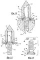
- Figure 10 is an exploded elevation view of a self-forging stud showing the forging collar in partial section.
- Figure 11 is a perspective view of the forging collar illustrating the forging rings at one end thereof.
- Figure 12 is an elevational view of a stud to be installed in a host plate prior to the forging of the forging collar onto the stud shaft.
- Figure 13 is an elevational view in partial cross-section of a self-forging stud installed in a host plate with the forging collar forged in place.
- Figure 14 illustrates a single-ended stud and an alternate forging collar configuration.
- Fig. 1 shows a double-ended stud 10, which is one of the preferred embodiments of the present invention, and illustrates its various components.
- Stud 10 in its preferred embodiment comprises a threaded upper shaft 12 and a co-axial lower threaded shaft 14.
- An annular flange 16 is positioned between shafts 12 and 14 and extends radially therefrom at a substantially right angle to the longitudinal axis of shafts 12 and 14.
- a shoulder 24 is adjacent the upper surface 18 of flange 16.
- Shoulder 24 extends radially from upper threaded shaft 12 wherein a top portion of the shoulder has a recess 26 immediately adjacent shaft 12 and a crown portion 28 at its outer periphery.
- the base of shoulder 24 is adjacent to the upper surface 18 of flange 16.
- Face 34 of shoulder 24 and upper surface 18 of flange 16 define an undercut 30 such that the diameter of shoulder 24 is smaller at its base than at the top or crown portion 28.
- At least one anti-rotation tab 22 protrudes into the area between crown portion 28 and upper surface 18 of flange 16.
- the self-attaching portion of the stud 10, comprising shoulder 24, anti-rotation tabs 22, and flange 16 is formed in a multi-step process. Typically, there are three to five steps or stations, more commonly called “blows" required in the heading process to fully form the attaching portion of the stud.
- the initial steps in the heading process are well known in the art and, while described herein, are not shown in the figures. Initially, coiled wire is fed into the heading machine and the wire is cut to the required length in and positioned in the first die. The die then begins to form annular flange 16, and shoulder 24 above annular flange 16.
- the shoulder 24 may be formed in a variety of shapes such as circular, square, octagonal, or any other polygonal shape with the preferred embodiment being a circular shoulder 24 as shown in Fig. 1.
- anti-rotation tabs 22 are partially formed on the top 18 of the annular flange 16.
- Anti-rotation tabs 22 can be formed as any geometric irregularity to prevent stud 10 from rotating in its host panel after installation described below. Each successive step or blow to the stud in the header moves progressively more metal towards the final shape of the stud.
- Figs. 2-3 illustrate the last station of the header process wherein a back angle between shoulder face 34 and top surface 18 of flange 16 is formed defining back angled portion 30 of the stud 10.
- the die 46 in the header tool has an aperture 48 into which is received upper shaft 12 of stud 10.
- Die 46 contains an annular nose 52 on the surface of the tool about the periphery of aperture 48.
- the advancement of the tool creates pressure that is applied to the top 28 of the shoulder 24 and forces the top or crown 28 of the shoulder 24 radially outward from the center of the stud and also creates recessed portion 26. This forms the back angled portion 30 between the top surface 18 of the annular flange 16 and the top 28 of the shoulder 24.
- shoulder 24 required for a particular application depends on the thickness of material into which it is to be installed.
- the height dimension from upper surface 18 of flange 16 to crown 28 is slightly greater than the material thickness into which it is to be installed.
- a stud 10 for installation in mating panel 76.
- flange 16 of stud 10 rests on an upper surface 64 of installation fixture 60 such that lower threaded shaft 14 extends into or is received by aperture 62.
- Mating panel 76 rests on top of anti-rotation tabs 22 on the upper surface 18 of flange 16. It will also be noted that the crown portion 28 of shoulder 24 extends above an upper surface of mating panel 76.
- An installation punch 66 having an aperture 67 therethrough is lowered over stud 10 such that upper threaded shaft 12 is received into aperture 67.
- the bottom portion of installation punch 66 has an inner bottom surface 70 immediately adjacent the periphery of aperture 67 and also has an annular protrusion 68 extending below inner bottom surface 70.
- the arrangement of crown 28, the upper surface of mating panel 76, inner bottom surface 70, and annular protrusion 68 is such that annular protrusion 68 contacts the upper surface of mating panel 76 substantially coincident with the contact of inner bottom surface 70 with crown 28.
- the size of the hole and mating panel 76 that receives the shoulder 24 of stud 10 is marginally greater than the largest diameter of shoulder 24. In such a manner, there is a relatively larger clearance between the aperture wall and shoulder 24 in the area of undercut 30 while maintaining a relatively minimum clearance between the aperture wall and the upper portion of shoulder 24 more proximate to crown 28.
- Fig. 5 the mating of stud 10 to mating panel 76 is complete wherein the installation punch has been forced toward installation fixture 60 with sufficient pressure that the material of mating panel 76 has flowed to contour over anti-rotation tabs 22 and come in contact with upper surface 18 of flange 16. Additionally, annular protrusion 68 by deformably bearing into the upper surface of mating panel 76 has caused the material about the periphery of shoulder 24 to flow into back angled area 30 and conform to the contour of shoulder face 34. Additionally, inner bottom surface 70 of installation punch 66 bearing against crown 28 has displaced crown 28 downward and radially outward to further engage mating panel 76.
- the mated panel 76 and stud 10 can be removed from the installation fixture 60 and installation punch 66.
- the final stud as installed is shown in Fig. 6 in partial cross-section showing the anti-rotation tab 22 extending into or above the bottom surface of mating panel 76.
- a recess 78 created by annular protrusion 68 is apparent in the top surface of mating panel 76 proximate to and about the periphery of crown 28.
- the mating panel 76 material about the periphery of shoulder 24 has flowed into contact with shoulder face 34 and into back angled area 30 thus firmly affixing stud 10 in mating panel 76.
- the self-attaching stud can accommodate a very high push out force.
- the angle, height, or diameter of shoulder and thus the bearing area of shoulder face 34 the push out force of the combined panel and stud can be adjusted to meet the needs for a particular application.
- stud 80 having an upper non-threaded shaft 81 and a lower threaded shaft 82, thereby illustrating that the upper shaft 81 and lower shaft 82 can be configured differently depending on the requirements for a particular installation.
- shoulder 83 is shown as a multi-sided element having a plurality of sides forming a periphery of the shoulder. In the illustrated embodiment, the shoulder is shown as an octagon, however, any multiple sided polygon can be utilized. Those skilled in the art will also readily recognize that the intersection of adjacent sides of the polygon forming shoulder 83 can also function as anti-rotation tabs and therefore eliminate the necessity to form anti-rotation tabs on the upper surface of flange 88.
- Stud 80 also includes a back angled area 87 and a crown area 85 to shoulder 83 wherein back angled area 87 and crown 85 are formed in a manner similar to stud 10 whereby a header tool die 46 having a nose 52 is pressed down upon a top surface of shoulder 83.
- Fig. 8 shows yet another embodiment wherein stud 90 is a single ended stud having one threaded shaft 91 extending upwardly from flange 94 and shoulder 92. Shoulder 92 and anti-rotation tabs 93 are identical to shoulder 24 and anti-rotation tabs 22 as shown in stud 10 above. Stud 90 is shown to illustrate that the lower shaft can be eliminated while still incorporating the features of the instant invention on a single ended stud.
- Figure 9 illustrates an alternate punch 73 for installing stud 10 in panel 76.
- Punch 73 mates panel 76 to the shoulder 24 of the stud 10 in a manner identical to that of punch 66.
- punch 73 also includes an outer annular area 74 that extends downwardly from the outer periphery of punch 73.
- outer annular area 74 deforms panel 76 downwardly around flange 16 so that the bottom surface of flange 16 and the bottom surface of panel 76 are substantially flush.
- a self-forging stud 110 has an upper shaft 112 and a lower shaft 114.
- Shaft 112 in this embodiment is non-threaded, and lower shaft 114 can be either threaded or unthreaded.
- lower shaft 114 can be eliminated depending on the desired use of stud 110.
- stud 110 shares many of the identical features as stud 10 in Fig. 1 wherein like features are similarly numbered and preceded by the numeral 1.
- upper shaft 112 and lower shaft 114 are coaxial and an annular flange 1-16 is positioned intermediate shafts 112 and 114.
- Shoulder 124 is adjacent the upper surface 118 of flange 116 and extends radially from upper shaft 112.
- a top portion of shoulder 124 has a recess 126 immediately adjacent shaft 112 and a crown portion 128 at its outer periphery.
- Shoulder 124 also has a face 134 that forms an acute angle with upper surface 118 to define an undercut 130 at the base of shoulder 24.
- the diameter of shoulder 124 is smaller at its base than at the top or crown portion 128.
- One or more anti-rotation tabs 122 can protrude into the area between crown portion 128 and upper surface 118.
- the self-attaching portion of stud 110, which comprises shoulder 124, anti-rotation tabs 122 and flange 116 is formed in a multi-step process identical to that of stud 10 as described above.
- Upper shaft 112 further includes a groove 132 formed at the base of shaft 112 immediately above shoulder 124. Groove 132 extends about the circumference of the base of shaft 112.
- Stud 110 also includes forging collar 140.
- Forging collar 140 is cylindrical in configuration and defines central aperture 142.
- the diameter of central aperture 142 is equal to or slightly smaller than the diameter of upper shaft 112 to create an interference fit when forging collar 140 is installed on shaft 112.
- Forging collar 140 at an end opposite from flange 116 can be configured according to the requirements of a particular application, and in this case is shown as a conical closed end 150.
- the end of forging collar 140 that is received onto shaft 112 in a sleeve-like fashion is most clearly illustrated in Fig. 11.
- the end of forging collar 140 comprises an inner forging ring 146 adjacent the periphery of central aperture 142 and an outer forging ring 148 radially spaced from inner forging ring 146.
- Forging rings 146 and 148 protrude from the end surface of forging tower 140 and define therebetween forging surface 144.
- FIG. 12 illustrates lower shaft 114 received in aperture 67 of installation fixture 60 with lower surface 120 of flange 116 resting on upper surface 64 of installation fixture 60. Shoulder 124 is received in an aperture of host plate 176 such that host place 176 rests on the upper surface of anti-rotation tabs 122.
- Forging collar 140 has been sleeved over upper shaft 112 such that outer forging ring 148 is in contact with the upper surface of host plate 176, and inner forging ring 146 is immediately adjacent groove 132 at the base of upper shaft 112.
- axial force is applied to forging collar 140, which is resisted by installation fixture 60.
- the axial force causes forging collar 140 to be advanced toward installation fixture 60 resulting in the self-forging mating of forging collar 140 for retention on upper pin 112.
- Fig. 13 shows a partial cross-section of the completed installation of stud 110 in host panel 176.
- outer forging ring 148 caused the material of panel 176 immediately adjacent the aperture therein to flow into the undercut 130 and around anti-rotation tabs 122 until host panel 176 contacted upper surface 118 of flange 116.
- forging surface 144 caused crown 128 to deform radially outward to further engage the host panel 176 at the periphery of the aperture.
- Inner forging ring 146 was upset at the top of shoulder 124 and deformed into groove 132, thus locking forging collar 140 onto upper shaft 112.
- Fig. 14 illustrates an alternate embodiment wherein stud 160 is a single-ended stud having a single shaft 161.
- Flange 164 and collar 162 are positioned at one end of shaft 161 and are configured in the same manner as flange 116 and collar 124 of stud 110.
- Anti-rotation tabs 163 are positioned intermediate to shoulder 162 and flange 164.
- Shaft 161 can be configured such that a base portion 167 of the shaft immediately above groove 166 is adapted for receiving forging collar 168. Further, a second portion 165 of shaft 161 having a diameter smaller than base portion 167 can be threaded, tapered, or otherwise configured as required for a particular application.
- Forging collar 168 is identical in configuration to forging collar 140 except that its thickness is substantially equal to or less than portion 167 of shaft 161.
- Collar 168 is forged on shaft 161 and attached to a host panel in the same manner as stud 110.
- a self-forging stud is identical to stud 110 as shown in Fig. 10 except that the stud includes a deformable second shoulder at the base of upper shaft. Second shoulder has a diameter greater than upper shaft but less than the diameter of shoulder. Shoulder is identical to shoulder 124 as shown and described with respect to Figs. 10-13 and thus is not further described here.
- a forging collar is substantially identical to the forging collar 140 as described in Figs. 10-13 except that inner forging ring 146 is eliminated and a dovetail recess is formed at the base of central aperture.
- Dovetail recess has a forging surface such that when forging collar is forced downwardly on stud outer forging ring of forging collar deforms host panel 76 thereabout in a manner identical to that shown in Figs. 10-13. Additionally, forging surface bears upon deformable second shoulder to deform second shoulder into dovetail recess. In this manner, forging collar is retained on stud by the deformed shoulder filling and bearing upon the surfaces of dovetail recess.
Landscapes
- Engineering & Computer Science (AREA)
- General Engineering & Computer Science (AREA)
- Mechanical Engineering (AREA)
- Forging (AREA)
- Connection Of Plates (AREA)
- Flanged Joints, Insulating Joints, And Other Joints (AREA)
- Dowels (AREA)
- Radar Systems Or Details Thereof (AREA)
- Joining Of Building Structures In Genera (AREA)
- Insertion Pins And Rivets (AREA)
Abstract
Description
- The invention relates to a fastener. The invention is specifically related to a self-attaching double or single ended stud.
- Studs are used by the automotive industry to assemble vehicles in which many components of various kinds are attached to metal plates or panels. For example studs are used to attach lamps, brackets, modules, and sheet metal parts to the vehicle. When such parts are attached a nut is placed over the end of the installed stud and the nut is tightened with rotating tools such as an air or electric torque gun, set to the specified torque values. The self-attaching stud must therefore have the necessary and sufficient anti-torque or rotation resistance (the force that keeps the stud from rotating on the mating metal plate when the nut is tightened on the stud).
- Examples for such studs are described in US 5,513,933, US 914,327 and US 5,251,370.
- When self-attaching studs are being driven into a metal panel the studs may be continuously supplied to the installation tooling through an outlet of a supply device, such as a hopper. Studs are easily adapted to automatic feeding machines because of the large length to diameter ratio. The larger the ratio the more efficient the high-speed feeding operations become.
- After a component is attached to the stud on the metal plate, external forces such as vibration and shear and tensile forces are applied to the joint (the stud and nut combination with the attached part). These forces act upon the stud from the pull through direction attempting to pull the studs from the metal plate in which they are attached. Therefore, the installed stud must have sufficient push out and pull out resistance. Previously, the only way to ensure a very high push out or pull out force was to weld the stud to the mating material. Earlier attempts to use double-ended studs that were not welded resulted in studs with very low push-in and push-out values. A low push-out value limits the number of applications in which the stud can be used, since a stud with a low push-out value can not attach parts of any significant amount of mass.
- Thus, there is a need in the industry for a stud that can be attached by means other than welding where the stud also has a very high push-out force, and where the stud can be configured as either a single-ended stud or a double-ended stud.
- The need is satisfied by a stud according to independent claim 1 and by a method according to independent claim 3.
- Figure 1 is a perspective view of a double-ended stud embodying the present invention.
- Figure 2 is an elevational view of a stud at the beginning of the final step of the stud forming process with the header tool (in section) partially advanced and beginning to form the back angled portion of the shoulder.
- Figure 3 is an elevational view of a stud at the final step of the stud forming process with the header tool (in section) fully advanced and the back angled shoulder fully formed.
- Figure 4, is an elevational view of a stud and installation punch in partial cross-section showing the finished stud inserted in a mating metal panel with the installation punch ready to deform the mating panel into the back angled portion of the stud.
- Figure 5 is an elevational view of the stud and installation punch in partial cross-section showing the punch having deformed the mating metal panel into the back angled portion of the stud.
- Figure 6, is an elevational view in partial cross-section of a stud installed in a mating panel illustrating the flow of panel metal into the back angled portion of the stud and into engagement with the anti-rotation feature of the stud.
- Figure 7 is a perspective view of an alternate embodiment of the stud wherein the back angled shoulder of the stud comprises a multi-sided polygon.
- Figure 8 shows an alternate embodiment of a single ended self-attaching stud.
- Figure 9 shows an elevation view of an installed stud similar to Figure 5 wherein the installation punch deforms the host panel to be flush with the flange bottom.
- Figure 10 is an exploded elevation view of a self-forging stud showing the forging collar in partial section.
- Figure 11 is a perspective view of the forging collar illustrating the forging rings at one end thereof.
- Figure 12 is an elevational view of a stud to be installed in a host plate prior to the forging of the forging collar onto the stud shaft.
- Figure 13 is an elevational view in partial cross-section of a self-forging stud installed in a host plate with the forging collar forged in place.
- Figure 14 illustrates a single-ended stud and an alternate forging collar configuration.
- For purposes of description herein, the terms "upper", "lower", right", "left", "rear", "front", "vertical", "horizontal", and derivatives thereof shall relate to the invention as oriented in Figs. 1 and 2. However, it is to be understood that the invention may assume various alternative orientations and step sequences, except where expressly specified to the contrary. It is also to be understood that the specific devices and processes illustrated in the attached drawings, and described in the following specification are simply exemplary embodiments of the inventive concept defined in the appended claims. Hence, specific dimensions and other physical characteristics relating to the embodiments disclosed herein are not to be considered as limiting, unless the claims expressly state otherwise.
- Turning to the drawings, Fig. 1 shows a double-
ended stud 10, which is one of the preferred embodiments of the present invention, and illustrates its various components. -
Stud 10 in its preferred embodiment comprises a threadedupper shaft 12 and a co-axial lower threadedshaft 14. Anannular flange 16 is positioned betweenshafts shafts shoulder 24 is adjacent theupper surface 18 offlange 16.Shoulder 24 extends radially from upper threadedshaft 12 wherein a top portion of the shoulder has arecess 26 immediatelyadjacent shaft 12 and acrown portion 28 at its outer periphery. The base ofshoulder 24 is adjacent to theupper surface 18 offlange 16.Face 34 ofshoulder 24 andupper surface 18 offlange 16 define an undercut 30 such that the diameter ofshoulder 24 is smaller at its base than at the top orcrown portion 28. At least oneanti-rotation tab 22 protrudes into the area betweencrown portion 28 andupper surface 18 offlange 16. - The self-attaching portion of the
stud 10, comprisingshoulder 24,anti-rotation tabs 22, andflange 16 is formed in a multi-step process. Typically, there are three to five steps or stations, more commonly called "blows" required in the heading process to fully form the attaching portion of the stud. The initial steps in the heading process are well known in the art and, while described herein, are not shown in the figures. Initially, coiled wire is fed into the heading machine and the wire is cut to the required length in and positioned in the first die. The die then begins to formannular flange 16, andshoulder 24 aboveannular flange 16. Theshoulder 24 may be formed in a variety of shapes such as circular, square, octagonal, or any other polygonal shape with the preferred embodiment being acircular shoulder 24 as shown in Fig. 1. In the later stages of the heading operationanti-rotation tabs 22 are partially formed on thetop 18 of theannular flange 16.Anti-rotation tabs 22 can be formed as any geometric irregularity to preventstud 10 from rotating in its host panel after installation described below. Each successive step or blow to the stud in the header moves progressively more metal towards the final shape of the stud. - Figs. 2-3 illustrate the last station of the header process wherein a back angle between
shoulder face 34 andtop surface 18 offlange 16 is formed defining back angledportion 30 of thestud 10. In this operation the die 46 in the header tool has anaperture 48 into which is receivedupper shaft 12 ofstud 10. Die 46 contains anannular nose 52 on the surface of the tool about the periphery ofaperture 48. As the header tool advances it forces theannular nose 52 on the die to make contact with the top ofshoulder 24 of thestud 10. The advancement of the tool creates pressure that is applied to thetop 28 of theshoulder 24 and forces the top orcrown 28 of theshoulder 24 radially outward from the center of the stud and also createsrecessed portion 26. This forms the backangled portion 30 between thetop surface 18 of theannular flange 16 and thetop 28 of theshoulder 24. - The height of
shoulder 24 required for a particular application depends on the thickness of material into which it is to be installed. The height dimension fromupper surface 18 offlange 16 to crown 28 is slightly greater than the material thickness into which it is to be installed. Those skilled in the art will readily recognize that since there are specific standard gauges of sheet material used in industry only a limited number of shoulder sizes need be produced to accommodate these standard gauges. - Referring now to Figs. 4-6, a
stud 10 according to the preferred embodiment is shown for installation inmating panel 76. As illustrated in Fig. 4,flange 16 ofstud 10 rests on anupper surface 64 ofinstallation fixture 60 such that lower threadedshaft 14 extends into or is received byaperture 62.Mating panel 76 rests on top ofanti-rotation tabs 22 on theupper surface 18 offlange 16. It will also be noted that thecrown portion 28 ofshoulder 24 extends above an upper surface ofmating panel 76. Aninstallation punch 66 having anaperture 67 therethrough is lowered overstud 10 such that upper threadedshaft 12 is received intoaperture 67. The bottom portion ofinstallation punch 66 has aninner bottom surface 70 immediately adjacent the periphery ofaperture 67 and also has anannular protrusion 68 extending belowinner bottom surface 70. The arrangement ofcrown 28, the upper surface ofmating panel 76,inner bottom surface 70, andannular protrusion 68 is such thatannular protrusion 68 contacts the upper surface ofmating panel 76 substantially coincident with the contact of innerbottom surface 70 withcrown 28. Those skilled in the art will understand that slight variations in this arrangement are possible while maintaining the intent and scope of the invention. Those skilled in the art will also understand that the size of the hole andmating panel 76 that receives theshoulder 24 ofstud 10 is marginally greater than the largest diameter ofshoulder 24. In such a manner, there is a relatively larger clearance between the aperture wall andshoulder 24 in the area of undercut 30 while maintaining a relatively minimum clearance between the aperture wall and the upper portion ofshoulder 24 more proximate to crown 28. - Turning now to Fig. 5, the mating of
stud 10 tomating panel 76 is complete wherein the installation punch has been forced towardinstallation fixture 60 with sufficient pressure that the material ofmating panel 76 has flowed to contour overanti-rotation tabs 22 and come in contact withupper surface 18 offlange 16. Additionally,annular protrusion 68 by deformably bearing into the upper surface ofmating panel 76 has caused the material about the periphery ofshoulder 24 to flow into backangled area 30 and conform to the contour ofshoulder face 34. Additionally,inner bottom surface 70 ofinstallation punch 66 bearing againstcrown 28 has displacedcrown 28 downward and radially outward to further engagemating panel 76. - Upon completion of the operation shown in Fig. 5, the mated
panel 76 andstud 10 can be removed from theinstallation fixture 60 andinstallation punch 66. The final stud as installed is shown in Fig. 6 in partial cross-section showing theanti-rotation tab 22 extending into or above the bottom surface ofmating panel 76. Arecess 78 created byannular protrusion 68 is apparent in the top surface ofmating panel 76 proximate to and about the periphery ofcrown 28. Additionally, themating panel 76 material about the periphery ofshoulder 24 has flowed into contact withshoulder face 34 and into backangled area 30 thus firmly affixingstud 10 inmating panel 76. - The flowing of the peripheral material of
panel 76 into the undercut or backangled area 30 ofpanel 24 and also as a result of the expansion ofcrown 28 into interfering contact with the material ofmating panel 76, the self-attaching stud can accommodate a very high push out force. Those skilled in the art will understand that by adjusting the angle, height, or diameter of shoulder and thus the bearing area ofshoulder face 34, the push out force of the combined panel and stud can be adjusted to meet the needs for a particular application. - Turning now to Fig. 7, an
alternate embodiment stud 80 is shown having an uppernon-threaded shaft 81 and a lower threadedshaft 82, thereby illustrating that theupper shaft 81 andlower shaft 82 can be configured differently depending on the requirements for a particular installation. Further,shoulder 83 is shown as a multi-sided element having a plurality of sides forming a periphery of the shoulder. In the illustrated embodiment, the shoulder is shown as an octagon, however, any multiple sided polygon can be utilized. Those skilled in the art will also readily recognize that the intersection of adjacent sides of thepolygon forming shoulder 83 can also function as anti-rotation tabs and therefore eliminate the necessity to form anti-rotation tabs on the upper surface offlange 88.Stud 80 also includes a backangled area 87 and acrown area 85 toshoulder 83 wherein backangled area 87 andcrown 85 are formed in a manner similar tostud 10 whereby a header tool die 46 having anose 52 is pressed down upon a top surface ofshoulder 83. - Fig. 8 shows yet another embodiment wherein
stud 90 is a single ended stud having one threadedshaft 91 extending upwardly fromflange 94 andshoulder 92.Shoulder 92 andanti-rotation tabs 93 are identical toshoulder 24 andanti-rotation tabs 22 as shown instud 10 above.Stud 90 is shown to illustrate that the lower shaft can be eliminated while still incorporating the features of the instant invention on a single ended stud. - Figure 9 illustrates an
alternate punch 73 for installingstud 10 inpanel 76.Punch 73mates panel 76 to theshoulder 24 of thestud 10 in a manner identical to that ofpunch 66. However, punch 73 also includes an outerannular area 74 that extends downwardly from the outer periphery ofpunch 73. Asinner bottom surface 70 andannular protrusion 68forgingly mate shoulder 24 andpanel 76, outerannular area 74 deformspanel 76 downwardly aroundflange 16 so that the bottom surface offlange 16 and the bottom surface ofpanel 76 are substantially flush. - Referring now to Fig. 10 a self-forging
stud 110 has anupper shaft 112 and alower shaft 114.Shaft 112 in this embodiment is non-threaded, andlower shaft 114 can be either threaded or unthreaded. Those practiced in the art will understand thatlower shaft 114 can be eliminated depending on the desired use ofstud 110. In this embodiment,stud 110 shares many of the identical features asstud 10 in Fig. 1 wherein like features are similarly numbered and preceded by the numeral 1. Thus,upper shaft 112 andlower shaft 114 are coaxial and an annular flange 1-16 is positionedintermediate shafts Shoulder 124 is adjacent theupper surface 118 offlange 116 and extends radially fromupper shaft 112. A top portion ofshoulder 124 has arecess 126 immediatelyadjacent shaft 112 and acrown portion 128 at its outer periphery.Shoulder 124 also has aface 134 that forms an acute angle withupper surface 118 to define an undercut 130 at the base ofshoulder 24. Thus, the diameter ofshoulder 124 is smaller at its base than at the top orcrown portion 128. One or moreanti-rotation tabs 122 can protrude into the area betweencrown portion 128 andupper surface 118. The self-attaching portion ofstud 110, which comprisesshoulder 124,anti-rotation tabs 122 andflange 116 is formed in a multi-step process identical to that ofstud 10 as described above.Upper shaft 112 further includes agroove 132 formed at the base ofshaft 112 immediately aboveshoulder 124.Groove 132 extends about the circumference of the base ofshaft 112. -
Stud 110 also includes forgingcollar 140. Forgingcollar 140 is cylindrical in configuration and definescentral aperture 142. The diameter ofcentral aperture 142 is equal to or slightly smaller than the diameter ofupper shaft 112 to create an interference fit when forgingcollar 140 is installed onshaft 112. Forgingcollar 140 at an end opposite fromflange 116 can be configured according to the requirements of a particular application, and in this case is shown as a conicalclosed end 150. The end of forgingcollar 140 that is received ontoshaft 112 in a sleeve-like fashion is most clearly illustrated in Fig. 11. The end of forgingcollar 140 comprises an inner forgingring 146 adjacent the periphery ofcentral aperture 142 and an outer forgingring 148 radially spaced from inner forgingring 146. Forgingrings tower 140 and definetherebetween forging surface 144. - Turning now to Figs. 12-13, the installation of
stud 110 in ahost plate 176 is illustrated. Fig. 12 illustrateslower shaft 114 received inaperture 67 ofinstallation fixture 60 withlower surface 120 offlange 116 resting onupper surface 64 ofinstallation fixture 60.Shoulder 124 is received in an aperture ofhost plate 176 such thathost place 176 rests on the upper surface ofanti-rotation tabs 122. Forgingcollar 140 has been sleeved overupper shaft 112 such that outer forgingring 148 is in contact with the upper surface ofhost plate 176, and inner forgingring 146 is immediatelyadjacent groove 132 at the base ofupper shaft 112. - An axial force is applied to forging
collar 140, which is resisted byinstallation fixture 60. The axial forcecauses forging collar 140 to be advanced towardinstallation fixture 60 resulting in the self-forging mating of forgingcollar 140 for retention onupper pin 112. Fig. 13 shows a partial cross-section of the completed installation ofstud 110 inhost panel 176. As the forgingcollar 140 advanced towardflange 116, outer forgingring 148 caused the material ofpanel 176 immediately adjacent the aperture therein to flow into the undercut 130 and aroundanti-rotation tabs 122 untilhost panel 176 contactedupper surface 118 offlange 116. At the same time, forgingsurface 144 causedcrown 128 to deform radially outward to further engage thehost panel 176 at the periphery of the aperture. Inner forgingring 146 was upset at the top ofshoulder 124 and deformed intogroove 132, thus locking forgingcollar 140 ontoupper shaft 112. - Fig. 14 illustrates an alternate embodiment wherein
stud 160 is a single-ended stud having asingle shaft 161.Flange 164 andcollar 162 are positioned at one end ofshaft 161 and are configured in the same manner asflange 116 andcollar 124 ofstud 110.Anti-rotation tabs 163 are positioned intermediate toshoulder 162 andflange 164.Shaft 161 can be configured such that abase portion 167 of the shaft immediately abovegroove 166 is adapted for receiving forgingcollar 168. Further, asecond portion 165 ofshaft 161 having a diameter smaller thanbase portion 167 can be threaded, tapered, or otherwise configured as required for a particular application. Forgingcollar 168 is identical in configuration to forgingcollar 140 except that its thickness is substantially equal to or less thanportion 167 ofshaft 161.Collar 168 is forged onshaft 161 and attached to a host panel in the same manner asstud 110. - In a variation of the embodiment shown in Figs. 10-13, a self-forging stud is identical to
stud 110 as shown in Fig. 10 except that the stud includes a deformable second shoulder at the base of upper shaft. Second shoulder has a diameter greater than upper shaft but less than the diameter of shoulder. Shoulder is identical toshoulder 124 as shown and described with respect to Figs. 10-13 and thus is not further described here. A forging collar is substantially identical to the forgingcollar 140 as described in Figs. 10-13 except that inner forgingring 146 is eliminated and a dovetail recess is formed at the base of central aperture. Dovetail recess has a forging surface such that when forging collar is forced downwardly on stud outer forging ring of forging collar deformshost panel 76 thereabout in a manner identical to that shown in Figs. 10-13. Additionally, forging surface bears upon deformable second shoulder to deform second shoulder into dovetail recess. In this manner, forging collar is retained on stud by the deformed shoulder filling and bearing upon the surfaces of dovetail recess. - In the foregoing description, those skilled in the art will readily appreciate that modifications may be made to the invention without departing from the concepts disclosed herein. Such modifications are to be considered as included in the following claims, unless these claims expressly state otherwise.
Claims (7)
- A stud (10, 80, 90, 110, 160) for installation in a host panel (76, 176) aperture, said stud (10, 80, 90, 110, 160) comprising:a shaft (12, 14, 81, 82, 91, 112, 114, 161) having a longitudinal axis;an annular flange (16, 88, 94, 116, 164) integral with and extending radially from said shaft (12, 14, 81, 82, 91, 112, 114, 161), and having an upper surface (18, 118) for supporting said panel (76, 176);a shoulder (24, 83, 92, 124, 162) integral with said shaft (12, 14, 81, 82, 91, 112, 114, 161) and said flange (16, 88, 94, 116, 164), said shoulder (24, 83, 92, 124, 162) having a top adjacent said shaft (12, 14, 81, 82, 91, 112, 114, 161) and a base adjacent to said flange (16, 88, 94, 116, 164), said shoulder (24, 83, 92, 124, 162) having a surface inclined radially from said shaft (12, 14, 81, 82, 91, 112, 114, 161) to an outer crown (28, 85, 128) defining a recess (26, 126), said shoulder (24, 83, 92, 124, 162) and said flange (16, 88, 94, 116, 164) defining an undercut (30, 87, 130) therebetween at said base such that a diameter of said shoulder (24, 83, 92, 124, 162) is smaller at said base than at said top.
- A stud (10, 80, 90, 110, 160) according to claim 1, additionally comprising at least one anti-rotation tab (22, 93, 163) intermediate said shoulder (24, 83, 92, 124, 162) top and said flange (16, 88, 94, 116, 164), said at least one anti-rotation tab (22, 93, 163) aligned for engagement with said host panel (76, 176).
- A method for installing a stud (10, 80, 90, 110, 160) in a host panel (76, 176) aperture wherein said stud (10, 80, 90, 110, 160) has a shaft portion (12, 14, 81, 82, 91, 112, 114, 161), an annular flange (16, 88, 94, 116, 164) and a shoulder (24, 83, 92, 124, 162) with an outer crown (28, 85, 128), wherein said shoulder (24, 83, 92, 124, 162) has a surface inclined radially from said shaft (12, 14, 81, 82, 91, 112, 114, 161) to said outer crown (28, 85, 128) defining a recess (26, 126) and said shoulder (24, 83, 92, 124, 162) has a face (34, 134) with a back angled portion which defines between said shoulder (24, 83, 92, 124, 162) and said flange (16, 88, 94, 116, 164) an undercut (30, 87, 130), said method comprising the steps:supporting one end of the stud (10, 80, 90, 110, 160) and the flange (16, 88, 94, 116, 164) with an installation fixture (60);placing the host panel aperture and an installation punch (66, 73) over an opposite end of the stud (10, 80, 90, 110, 160) wherein the installation punch (66, 73) has a face portion (70) bearing on the shoulder crown (28, 85, 128) and an annular protrusion (68) bearing on the panel area proximate to the panel aperture receiving the stud (10, 80, 90, 110, 160);applying force to the punch (66, 73) in a direction toward the installation fixture (60); therebyflowing the panel material defining the panel aperture into the back angled portion defining the undercut (30, 87, 130); anddeflecting the shoulder crown (28, 85, 128) radially outward to engage the panel (76, 176) at the periphery of the panel aperture.
- A method according to claim 3, wherein the annular flange (16, 88, 94, 116, 164) has anti-rotation tabs (22, 93, 163) projecting from it and the method comprises deforming the panel (76, 176) around the anti-rotation tabs (22, 93, 163).
- A stud (10, 80, 90, 110, 160) and panel (76, 176) assembly, comprising:a panel (76, 176); anda stud (10, 80, 90, 110, 160) according to any of claims 1 or 2, whereinsaid panel (76, 176) has been deformed around said shoulder portion (24, 83, 92, 124, 162) thereby retaining said panel (76, 176) to said stud (10, 80, 90, 110, 160).
- A stud (10, 80, 90, 110, 160) and panel (76, 176) assembly according to claim 5, wherein the flange portion (16, 88, 94, 116, 164) includes a plurality of anti-rotation tabs (22, 93, 163) on its upper surface (76, 176) and the panel (76, 176) is deformed into spaces between said anti-rotation tabs (22, 93, 163).
- A stud (10, 80, 90, 110, 160) and panel (76, 176) assembly according to claim 6, wherein said anti-rotation tabs (22, 93, 163) are in the form of a plurality of circumferentially spaced radial ribs projecting from said upper surface (18, 118) of said annular flange (16, 88, 94, 116, 164).
Applications Claiming Priority (5)
| Application Number | Priority Date | Filing Date | Title |
|---|---|---|---|
| US909260 | 1992-07-06 | ||
| US09/909,260 US6592311B2 (en) | 2001-07-19 | 2001-07-19 | Double-ended self-attaching stud |
| US09/957,720 US6491487B1 (en) | 2001-07-19 | 2001-09-21 | Double-ended self-attaching stud |
| US957720 | 2001-09-21 | ||
| PCT/US2002/003746 WO2003008817A1 (en) | 2001-07-19 | 2002-02-07 | Locating pin on double ended stud |
Publications (3)
| Publication Number | Publication Date |
|---|---|
| EP1417419A1 EP1417419A1 (en) | 2004-05-12 |
| EP1417419A4 EP1417419A4 (en) | 2005-03-30 |
| EP1417419B1 true EP1417419B1 (en) | 2006-08-16 |
Family
ID=27129517
Family Applications (1)
| Application Number | Title | Priority Date | Filing Date |
|---|---|---|---|
| EP02704395A Expired - Lifetime EP1417419B1 (en) | 2001-07-19 | 2002-02-07 | Locating pin on double ended stud |
Country Status (11)
| Country | Link |
|---|---|
| US (1) | US6491487B1 (en) |
| EP (1) | EP1417419B1 (en) |
| JP (1) | JP4133813B2 (en) |
| CN (1) | CN1524164A (en) |
| AT (1) | ATE336666T1 (en) |
| BR (1) | BR0211037A (en) |
| CA (1) | CA2448716A1 (en) |
| DE (1) | DE60214008T2 (en) |
| ES (1) | ES2272671T3 (en) |
| MX (1) | MXPA04000501A (en) |
| WO (1) | WO2003008817A1 (en) |
Families Citing this family (38)
| Publication number | Priority date | Publication date | Assignee | Title |
|---|---|---|---|---|
| US6746285B2 (en) * | 2001-02-20 | 2004-06-08 | Newfrey Llc | Grounding stud |
| US7056161B2 (en) | 2001-02-20 | 2006-06-06 | Newfrey Llc | Grounding stud |
| US6864015B2 (en) * | 2001-07-17 | 2005-03-08 | Delphi Technologies, Inc. | Anti-rotation terminal connection assembly |
| US7698799B2 (en) | 2001-07-19 | 2010-04-20 | Whitesell International Corporation | Method of attaching a clinch spacer to a panel |
| US7124492B2 (en) * | 2001-07-19 | 2006-10-24 | Whitesell International Corporation | Fastener, method of attaching a fastener to a panel and fastener and panel assembly |
| US6641326B2 (en) * | 2001-12-21 | 2003-11-04 | General Electric Company | Removable stud for joining casing flanges |
| US20050111934A1 (en) * | 2003-11-14 | 2005-05-26 | Ladouceur Harold A. | Self-riveting male fastener and panel assembly |
| US20050025605A1 (en) * | 2003-07-30 | 2005-02-03 | Vrana John J. | Locator stud and method of assembly |
| GB0413866D0 (en) * | 2004-06-21 | 2004-07-21 | Bas Components Ltd | Captive fastener |
| US7282662B2 (en) * | 2005-12-12 | 2007-10-16 | Nelson Stud Welding, Inc. | Paint groove stud |
| US7614125B2 (en) * | 2006-08-07 | 2009-11-10 | Newfrey Llc | Positive hold tube weld stud assembly |
| DE102006056065B4 (en) | 2006-11-20 | 2018-08-09 | Newfrey Llc | Pre-assembled contacting unit and mounting arrangement |
| JP4345988B2 (en) * | 2007-04-16 | 2009-10-14 | Ntn株式会社 | Wheel bearing device |
| DE102007022624A1 (en) * | 2007-05-15 | 2008-11-27 | Nedschroef Plettenberg Gmbh | Unround punch nut |
| US7892049B1 (en) * | 2009-08-18 | 2011-02-22 | GM Global Technology Operations LLC | Electrical connector assemblies |
| KR101214011B1 (en) * | 2010-05-31 | 2012-12-26 | 로베르트 보쉬 게엠베하 | Structure of electrode terminal and secondary battery using the same |
| CN101968070B (en) * | 2010-09-29 | 2012-02-15 | 芜湖恒丰机械有限公司 | Through bolt |
| EP2600503B1 (en) * | 2011-12-02 | 2019-02-13 | Lakeview Innovation Ltd. | Brush support for a brush commuted electric motor and electric motor |
| CN103511429A (en) * | 2012-06-21 | 2014-01-15 | 昆山神昌精密金属制品有限公司 | Stud |
| WO2014004989A1 (en) * | 2012-06-29 | 2014-01-03 | Infastech Intellectual Properties Pte. Ltd. | Self-clinching fastener |
| FI124657B (en) * | 2012-12-31 | 2014-11-28 | Suunto Oy | Male connector for telemetric receiver |
| DE102013101068A1 (en) * | 2013-02-01 | 2014-08-07 | Ejot Tezmak Baglanti Elemanlari Teknolojileri San. Ve Tic. A.S. | Einpressbolzen |
| DE102013113763A1 (en) * | 2013-12-10 | 2015-06-11 | Dr. Ing. H.C. F. Porsche Aktiengesellschaft | Adhesive bolts and mounting method |
| US9200661B2 (en) * | 2013-12-19 | 2015-12-01 | GM Global Technology Operations LLC | Flow drill screw |
| US9680239B2 (en) | 2014-04-23 | 2017-06-13 | Ramco Specialties, Inc. | Grounding stud and electrical connections |
| DE102014211656A1 (en) * | 2014-06-18 | 2016-01-07 | Bayerische Motoren Werke Aktiengesellschaft | Method for pressing a ball with a first component and component connection |
| US10335907B2 (en) | 2015-05-18 | 2019-07-02 | Reo Hydro-Pierce, Inc. | Method and apparatus for installing pierce nuts |
| KR102451126B1 (en) | 2015-12-18 | 2022-10-05 | 주식회사 성우하이텍 | Mounting bolt for sub-frame |
| USD803267S1 (en) * | 2016-04-08 | 2017-11-21 | Enrique J. Baiz | Solenoid cover |
| USD803266S1 (en) * | 2016-04-08 | 2017-11-21 | Enrique J. Baiz | Solenoid cover |
| EP3634662A4 (en) * | 2017-05-09 | 2021-05-19 | Penn Engineering & Manufacturing Corp. | Fastener and installation method for very thin sheets |
| CN107477069A (en) * | 2017-07-31 | 2017-12-15 | 太仓市众翔精密五金有限公司 | A kind of wear-resisting stud for exempting from driver |
| US10876556B2 (en) * | 2018-03-26 | 2020-12-29 | GM Global Technology Operations LLC | Double-ended dual attached fastener |
| DE102019110635A1 (en) | 2018-05-02 | 2019-11-07 | Profil Verbindungstechnik Gmbh & Co. Kg | Assembly part consisting of a component and an element with a head part and a collar arranged on one side of the head part and production method |
| JP7156124B2 (en) * | 2019-03-25 | 2022-10-19 | 株式会社Jvcケンウッド | Stud pins and stud pin crimping methods |
| DE112020007083T5 (en) * | 2020-06-19 | 2023-02-02 | Aoyama Seisakusho Co., Ltd. | Crimp locking structure of a stud, crimp locking method for a crimp stud, and crimp die |
| DE102020134255A1 (en) * | 2020-12-18 | 2022-06-23 | Te Connectivity Germany Gmbh | Busbar contact for attachment to a busbar, and method of attaching a busbar contact |
| FR3118833A1 (en) * | 2021-01-12 | 2022-07-15 | Valeo Systemes Thermiques | Device for thermal management of an electrical and/or electronic element for a motor vehicle. |
Family Cites Families (9)
| Publication number | Priority date | Publication date | Assignee | Title |
|---|---|---|---|---|
| US914327A (en) * | 1908-05-16 | 1909-03-02 | Standard Underground Cable Company | Binding-post. |
| US1114013A (en) * | 1914-01-16 | 1914-10-20 | William B Millar | Concrete-insert. |
| US2972730A (en) * | 1955-05-16 | 1961-02-21 | Cambridge Thermionic Corp | Pressure mounted lug |
| US3820579A (en) * | 1971-03-29 | 1974-06-28 | Southco | Blind stud fastener |
| US5441417A (en) * | 1981-01-28 | 1995-08-15 | Multifastener Corporation | Electrical grounding stud |
| US4543023A (en) * | 1981-05-28 | 1985-09-24 | Russell, Burdsall & Ward Corporation | Fastener |
| US5251370A (en) * | 1991-10-31 | 1993-10-12 | Profil Verbindungstechnik Gmbh & Co. | Method of attaching a fastening element to a panel |
| US6125524A (en) * | 1994-03-25 | 2000-10-03 | Multifastener Corporation | Rivetable element, assembly, method of assembly and riveting die |
| US5513933A (en) * | 1994-04-04 | 1996-05-07 | Textron Inc. | Staked fastener with undercut |
-
2001
- 2001-09-21 US US09/957,720 patent/US6491487B1/en not_active Expired - Fee Related
-
2002
- 2002-02-07 BR BR0211037-7A patent/BR0211037A/en not_active Application Discontinuation
- 2002-02-07 CA CA002448716A patent/CA2448716A1/en not_active Abandoned
- 2002-02-07 DE DE60214008T patent/DE60214008T2/en not_active Expired - Lifetime
- 2002-02-07 CN CNA028137019A patent/CN1524164A/en active Pending
- 2002-02-07 AT AT02704395T patent/ATE336666T1/en not_active IP Right Cessation
- 2002-02-07 ES ES02704395T patent/ES2272671T3/en not_active Expired - Lifetime
- 2002-02-07 EP EP02704395A patent/EP1417419B1/en not_active Expired - Lifetime
- 2002-02-07 JP JP2003514129A patent/JP4133813B2/en not_active Expired - Fee Related
- 2002-02-07 WO PCT/US2002/003746 patent/WO2003008817A1/en not_active Ceased
- 2002-02-07 MX MXPA04000501A patent/MXPA04000501A/en active IP Right Grant
Also Published As
| Publication number | Publication date |
|---|---|
| EP1417419A1 (en) | 2004-05-12 |
| JP2005508485A (en) | 2005-03-31 |
| JP4133813B2 (en) | 2008-08-13 |
| ATE336666T1 (en) | 2006-09-15 |
| MXPA04000501A (en) | 2005-07-25 |
| ES2272671T3 (en) | 2007-05-01 |
| BR0211037A (en) | 2005-04-19 |
| WO2003008817A1 (en) | 2003-01-30 |
| EP1417419A4 (en) | 2005-03-30 |
| DE60214008T2 (en) | 2007-03-29 |
| CN1524164A (en) | 2004-08-25 |
| DE60214008D1 (en) | 2006-09-28 |
| US6491487B1 (en) | 2002-12-10 |
| CA2448716A1 (en) | 2003-01-30 |
Similar Documents
| Publication | Publication Date | Title |
|---|---|---|
| US6491487B1 (en) | Double-ended self-attaching stud | |
| US6592311B2 (en) | Double-ended self-attaching stud | |
| US6125524A (en) | Rivetable element, assembly, method of assembly and riveting die | |
| KR100460232B1 (en) | Joining method and component assembly of fastener members | |
| EP1532371B1 (en) | Clinch-type blind nut | |
| JP3781057B2 (en) | Rivetable element, assembly, assembly method and riveting die | |
| US4018257A (en) | Self-flanging nut and joint construction | |
| US3253631A (en) | Cold-formed self-piercing nut | |
| US5445483A (en) | Female clinch fastener with cold-formed locking flange and associated installation method | |
| KR100249118B1 (en) | How to attach the fastening element to the panel | |
| EP0571930B1 (en) | Self-attaching fastening element and method of attachment | |
| US20060062652A1 (en) | Self-attaching nut | |
| US9897129B2 (en) | Captive floating flare nut | |
| US5309618A (en) | Method of attaching a female fastener assembly to a panel | |
| US3828382A (en) | Method of manufacturing a fastener such as a bolt, rivet, or the like | |
| US6893198B2 (en) | Self-attaching female fastener element and method of attachment | |
| KR20020037744A (en) | Method for placing a functional element; die. functional element; assembly element and die arrangement | |
| US5560094A (en) | Method of attaching a fastener to a panel | |
| US7152294B2 (en) | Self-attaching female fastener element and method of installation | |
| US8584343B2 (en) | Method for the application of a joint or function element to planar material rivet connection | |
| CN114810772B (en) | Self-stamping functional element, component assembly and method for producing a component assembly | |
| CN102889275B (en) | Connecting element, part assembly and method for forming the part assembly | |
| JP5148074B2 (en) | Member and part assembly that can be attached to sheet metal part by riveting, and method for manufacturing the part assembly | |
| MXPA96004264A (en) | Rivetable element, assembly, method of assembly and assembly remac |
Legal Events
| Date | Code | Title | Description |
|---|---|---|---|
| PUAI | Public reference made under article 153(3) epc to a published international application that has entered the european phase |
Free format text: ORIGINAL CODE: 0009012 |
|
| 17P | Request for examination filed |
Effective date: 20040216 |
|
| AK | Designated contracting states |
Kind code of ref document: A1 Designated state(s): AT BE CH CY DE DK ES FI FR GB GR IE IT LI LU MC NL PT SE TR |
|
| AX | Request for extension of the european patent |
Extension state: AL LT LV MK RO SI |
|
| A4 | Supplementary search report drawn up and despatched |
Effective date: 20050216 |
|
| 17Q | First examination report despatched |
Effective date: 20050620 |
|
| RAP1 | Party data changed (applicant data changed or rights of an application transferred) |
Owner name: WHITESELL INTERNATIONAL CORPORATION |
|
| GRAP | Despatch of communication of intention to grant a patent |
Free format text: ORIGINAL CODE: EPIDOSNIGR1 |
|
| GRAS | Grant fee paid |
Free format text: ORIGINAL CODE: EPIDOSNIGR3 |
|
| GRAA | (expected) grant |
Free format text: ORIGINAL CODE: 0009210 |
|
| AK | Designated contracting states |
Kind code of ref document: B1 Designated state(s): AT BE CH CY DE DK ES FI FR GB GR IE IT LI LU MC NL PT SE TR |
|
| PG25 | Lapsed in a contracting state [announced via postgrant information from national office to epo] |
Ref country code: FI Free format text: LAPSE BECAUSE OF FAILURE TO SUBMIT A TRANSLATION OF THE DESCRIPTION OR TO PAY THE FEE WITHIN THE PRESCRIBED TIME-LIMIT Effective date: 20060816 Ref country code: CH Free format text: LAPSE BECAUSE OF FAILURE TO SUBMIT A TRANSLATION OF THE DESCRIPTION OR TO PAY THE FEE WITHIN THE PRESCRIBED TIME-LIMIT Effective date: 20060816 Ref country code: IT Free format text: LAPSE BECAUSE OF FAILURE TO SUBMIT A TRANSLATION OF THE DESCRIPTION OR TO PAY THE FEE WITHIN THE PRESCRIBED TIME-LIMIT;WARNING: LAPSES OF ITALIAN PATENTS WITH EFFECTIVE DATE BEFORE 2007 MAY HAVE OCCURRED AT ANY TIME BEFORE 2007. THE CORRECT EFFECTIVE DATE MAY BE DIFFERENT FROM THE ONE RECORDED. Effective date: 20060816 Ref country code: BE Free format text: LAPSE BECAUSE OF FAILURE TO SUBMIT A TRANSLATION OF THE DESCRIPTION OR TO PAY THE FEE WITHIN THE PRESCRIBED TIME-LIMIT Effective date: 20060816 Ref country code: NL Free format text: LAPSE BECAUSE OF FAILURE TO SUBMIT A TRANSLATION OF THE DESCRIPTION OR TO PAY THE FEE WITHIN THE PRESCRIBED TIME-LIMIT Effective date: 20060816 Ref country code: AT Free format text: LAPSE BECAUSE OF FAILURE TO SUBMIT A TRANSLATION OF THE DESCRIPTION OR TO PAY THE FEE WITHIN THE PRESCRIBED TIME-LIMIT Effective date: 20060816 Ref country code: LI Free format text: LAPSE BECAUSE OF FAILURE TO SUBMIT A TRANSLATION OF THE DESCRIPTION OR TO PAY THE FEE WITHIN THE PRESCRIBED TIME-LIMIT Effective date: 20060816 |
|
| REG | Reference to a national code |
Ref country code: GB Ref legal event code: FG4D |
|
| REG | Reference to a national code |
Ref country code: CH Ref legal event code: EP |
|
| REG | Reference to a national code |
Ref country code: IE Ref legal event code: FG4D |
|
| REF | Corresponds to: |
Ref document number: 60214008 Country of ref document: DE Date of ref document: 20060928 Kind code of ref document: P |
|
| PG25 | Lapsed in a contracting state [announced via postgrant information from national office to epo] |
Ref country code: SE Free format text: LAPSE BECAUSE OF FAILURE TO SUBMIT A TRANSLATION OF THE DESCRIPTION OR TO PAY THE FEE WITHIN THE PRESCRIBED TIME-LIMIT Effective date: 20061116 Ref country code: DK Free format text: LAPSE BECAUSE OF FAILURE TO SUBMIT A TRANSLATION OF THE DESCRIPTION OR TO PAY THE FEE WITHIN THE PRESCRIBED TIME-LIMIT Effective date: 20061116 |
|
| PG25 | Lapsed in a contracting state [announced via postgrant information from national office to epo] |
Ref country code: PT Free format text: LAPSE BECAUSE OF FAILURE TO SUBMIT A TRANSLATION OF THE DESCRIPTION OR TO PAY THE FEE WITHIN THE PRESCRIBED TIME-LIMIT Effective date: 20070116 |
|
| NLV1 | Nl: lapsed or annulled due to failure to fulfill the requirements of art. 29p and 29m of the patents act | ||
| PG25 | Lapsed in a contracting state [announced via postgrant information from national office to epo] |
Ref country code: MC Free format text: LAPSE BECAUSE OF NON-PAYMENT OF DUE FEES Effective date: 20070228 |
|
| REG | Reference to a national code |
Ref country code: CH Ref legal event code: PL |
|
| ET | Fr: translation filed | ||
| REG | Reference to a national code |
Ref country code: ES Ref legal event code: FG2A Ref document number: 2272671 Country of ref document: ES Kind code of ref document: T3 |
|
| PLBE | No opposition filed within time limit |
Free format text: ORIGINAL CODE: 0009261 |
|
| STAA | Information on the status of an ep patent application or granted ep patent |
Free format text: STATUS: NO OPPOSITION FILED WITHIN TIME LIMIT |
|
| 26N | No opposition filed |
Effective date: 20070518 |
|
| PG25 | Lapsed in a contracting state [announced via postgrant information from national office to epo] |
Ref country code: IE Free format text: LAPSE BECAUSE OF NON-PAYMENT OF DUE FEES Effective date: 20070207 |
|
| PG25 | Lapsed in a contracting state [announced via postgrant information from national office to epo] |
Ref country code: GR Free format text: LAPSE BECAUSE OF FAILURE TO SUBMIT A TRANSLATION OF THE DESCRIPTION OR TO PAY THE FEE WITHIN THE PRESCRIBED TIME-LIMIT Effective date: 20061117 |
|
| PG25 | Lapsed in a contracting state [announced via postgrant information from national office to epo] |
Ref country code: LU Free format text: LAPSE BECAUSE OF NON-PAYMENT OF DUE FEES Effective date: 20070207 Ref country code: CY Free format text: LAPSE BECAUSE OF FAILURE TO SUBMIT A TRANSLATION OF THE DESCRIPTION OR TO PAY THE FEE WITHIN THE PRESCRIBED TIME-LIMIT Effective date: 20060816 |
|
| PG25 | Lapsed in a contracting state [announced via postgrant information from national office to epo] |
Ref country code: TR Free format text: LAPSE BECAUSE OF FAILURE TO SUBMIT A TRANSLATION OF THE DESCRIPTION OR TO PAY THE FEE WITHIN THE PRESCRIBED TIME-LIMIT Effective date: 20060816 |
|
| REG | Reference to a national code |
Ref country code: FR Ref legal event code: PLFP Year of fee payment: 15 |
|
| REG | Reference to a national code |
Ref country code: FR Ref legal event code: PLFP Year of fee payment: 16 |
|
| REG | Reference to a national code |
Ref country code: DE Ref legal event code: R082 Ref document number: 60214008 Country of ref document: DE Representative=s name: BARDEHLE PAGENBERG PARTNERSCHAFT MBB PATENTANW, DE Ref country code: DE Ref legal event code: R081 Ref document number: 60214008 Country of ref document: DE Owner name: WHITESELL FORMED COMPONENTS, INC, WATERFORD, US Free format text: FORMER OWNER: WHITESELL INTERNATIONAL CORP., TAYLOR, MICH., US |
|
| REG | Reference to a national code |
Ref country code: ES Ref legal event code: PC2A Owner name: WHITESELL FORMED COMPONENTS, INC. Effective date: 20171023 |
|
| REG | Reference to a national code |
Ref country code: FR Ref legal event code: CA Effective date: 20171109 Ref country code: FR Ref legal event code: CD Owner name: WHITESELL FORMED COMPONENTS, INC., US Effective date: 20171109 |
|
| REG | Reference to a national code |
Ref country code: FR Ref legal event code: PLFP Year of fee payment: 17 |
|
| PGFP | Annual fee paid to national office [announced via postgrant information from national office to epo] |
Ref country code: FR Payment date: 20210113 Year of fee payment: 20 |
|
| PGFP | Annual fee paid to national office [announced via postgrant information from national office to epo] |
Ref country code: DE Payment date: 20210126 Year of fee payment: 20 Ref country code: GB Payment date: 20210127 Year of fee payment: 20 Ref country code: ES Payment date: 20210310 Year of fee payment: 20 |
|
| PGFP | Annual fee paid to national office [announced via postgrant information from national office to epo] |
Ref country code: IT Payment date: 20210112 Year of fee payment: 20 |
|
| REG | Reference to a national code |
Ref country code: GB Ref legal event code: PE20 Expiry date: 20220206 |
|
| PG25 | Lapsed in a contracting state [announced via postgrant information from national office to epo] |
Ref country code: GB Free format text: LAPSE BECAUSE OF EXPIRATION OF PROTECTION Effective date: 20220206 |
|
| REG | Reference to a national code |
Ref country code: ES Ref legal event code: FD2A Effective date: 20220526 |
|
| PG25 | Lapsed in a contracting state [announced via postgrant information from national office to epo] |
Ref country code: ES Free format text: LAPSE BECAUSE OF EXPIRATION OF PROTECTION Effective date: 20220208 |