EP1417136B1 - Product holder with point-of-sale security - Google Patents
Product holder with point-of-sale security Download PDFInfo
- Publication number
- EP1417136B1 EP1417136B1 EP02754013A EP02754013A EP1417136B1 EP 1417136 B1 EP1417136 B1 EP 1417136B1 EP 02754013 A EP02754013 A EP 02754013A EP 02754013 A EP02754013 A EP 02754013A EP 1417136 B1 EP1417136 B1 EP 1417136B1
- Authority
- EP
- European Patent Office
- Prior art keywords
- cap
- container
- point
- security system
- stop member
- Prior art date
- Legal status (The legal status is an assumption and is not a legal conclusion. Google has not performed a legal analysis and makes no representation as to the accuracy of the status listed.)
- Expired - Lifetime
Links
- 235000001674 Agaricus brunnescens Nutrition 0.000 claims description 8
- 238000003780 insertion Methods 0.000 description 2
- 230000037431 insertion Effects 0.000 description 2
- 238000012986 modification Methods 0.000 description 2
- 230000004048 modification Effects 0.000 description 2
- 238000013475 authorization Methods 0.000 description 1
- 239000000820 nonprescription drug Substances 0.000 description 1
- 230000000717 retained effect Effects 0.000 description 1
- 238000000926 separation method Methods 0.000 description 1
- 239000002453 shampoo Substances 0.000 description 1
- 229940034610 toothpaste Drugs 0.000 description 1
- 239000000606 toothpaste Substances 0.000 description 1
Images







Classifications
-
- A—HUMAN NECESSITIES
- A47—FURNITURE; DOMESTIC ARTICLES OR APPLIANCES; COFFEE MILLS; SPICE MILLS; SUCTION CLEANERS IN GENERAL
- A47F—SPECIAL FURNITURE, FITTINGS, OR ACCESSORIES FOR SHOPS, STOREHOUSES, BARS, RESTAURANTS OR THE LIKE; PAYING COUNTERS
- A47F5/00—Show stands, hangers, or shelves characterised by their constructional features
- A47F5/08—Show stands, hangers, or shelves characterised by their constructional features secured to the wall, ceiling, or the like; Wall-bracket display devices
- A47F5/0807—Display panels, grids or rods used for suspending merchandise or cards supporting articles; Movable brackets therefor
- A47F5/0861—Anti-theft means therefor
-
- B—PERFORMING OPERATIONS; TRANSPORTING
- B65—CONVEYING; PACKING; STORING; HANDLING THIN OR FILAMENTARY MATERIAL
- B65D—CONTAINERS FOR STORAGE OR TRANSPORT OF ARTICLES OR MATERIALS, e.g. BAGS, BARRELS, BOTTLES, BOXES, CANS, CARTONS, CRATES, DRUMS, JARS, TANKS, HOPPERS, FORWARDING CONTAINERS; ACCESSORIES, CLOSURES, OR FITTINGS THEREFOR; PACKAGING ELEMENTS; PACKAGES
- B65D50/00—Closures with means for discouraging unauthorised opening or removal thereof, with or without indicating means, e.g. child-proof closures
- B65D50/02—Closures with means for discouraging unauthorised opening or removal thereof, with or without indicating means, e.g. child-proof closures openable or removable by the combination of plural actions
- B65D50/04—Closures with means for discouraging unauthorised opening or removal thereof, with or without indicating means, e.g. child-proof closures openable or removable by the combination of plural actions requiring the combination of simultaneous actions, e.g. depressing and turning, lifting and turning, maintaining a part and turning another one
- B65D50/045—Closures with means for discouraging unauthorised opening or removal thereof, with or without indicating means, e.g. child-proof closures openable or removable by the combination of plural actions requiring the combination of simultaneous actions, e.g. depressing and turning, lifting and turning, maintaining a part and turning another one where one action elastically deforms or deflects at least part of the closure, the container or an intermediate element, e.g. a ring
-
- B—PERFORMING OPERATIONS; TRANSPORTING
- B65—CONVEYING; PACKING; STORING; HANDLING THIN OR FILAMENTARY MATERIAL
- B65D—CONTAINERS FOR STORAGE OR TRANSPORT OF ARTICLES OR MATERIALS, e.g. BAGS, BARRELS, BOTTLES, BOXES, CANS, CARTONS, CRATES, DRUMS, JARS, TANKS, HOPPERS, FORWARDING CONTAINERS; ACCESSORIES, CLOSURES, OR FITTINGS THEREFOR; PACKAGING ELEMENTS; PACKAGES
- B65D50/00—Closures with means for discouraging unauthorised opening or removal thereof, with or without indicating means, e.g. child-proof closures
- B65D50/02—Closures with means for discouraging unauthorised opening or removal thereof, with or without indicating means, e.g. child-proof closures openable or removable by the combination of plural actions
- B65D50/06—Closures with means for discouraging unauthorised opening or removal thereof, with or without indicating means, e.g. child-proof closures openable or removable by the combination of plural actions requiring the combination of different actions in succession
-
- B—PERFORMING OPERATIONS; TRANSPORTING
- B65—CONVEYING; PACKING; STORING; HANDLING THIN OR FILAMENTARY MATERIAL
- B65D—CONTAINERS FOR STORAGE OR TRANSPORT OF ARTICLES OR MATERIALS, e.g. BAGS, BARRELS, BOTTLES, BOXES, CANS, CARTONS, CRATES, DRUMS, JARS, TANKS, HOPPERS, FORWARDING CONTAINERS; ACCESSORIES, CLOSURES, OR FITTINGS THEREFOR; PACKAGING ELEMENTS; PACKAGES
- B65D73/00—Packages comprising articles attached to cards, sheets or webs
- B65D73/0064—Packages comprising articles attached to cards, sheets or webs the articles being supported by or suspended from a tag-like element
Definitions
- This invention relates to a product container having point-of-sale security inherent therein. After purchase, the point-of-sale security feature is disabled, and the product container may be used by the consumer to store the article or articles which are sold in the product container.
- a second object of the invention is to provide an attachment for such container having an article therein, so that such point-of-sale security may be provided.
- a third object of the present invention is to provide such an attachment which cannot readily be bypassed or disabled, thereby voiding such point-of-sale security.
- the present invention provides a point-of-sale security system for a product according to claim 1.
- the point-of-sale security system includes a container for containing the product, and a holder assembly, the holder assembly including a closure device for the container.
- the closure device and the container are provided with cooperative members which are operatively associated with the container and with the closure device.
- the cooperative members are configured such that, when enabled by a stop member, the container is prevented from being decoupled from the device and when the stop member is disabled, the container can be decoupled from the holder device.
- the stop member is configured to selectively prevent the decoupling of the container and the device.
- the closure device is a cap for the container, the cap being integral with, and projecting outwardly from, the holder assembly, e.g., the hang tag.
- the cap includes a pair of flexibly-movable parts, the holder assembly, e.g., the hang tag, is integrally associated with the stop member, and the holder member, e.g., the hang tag is configured to be severed, along with its stop member, from the cap and to be discarded. This disables the stop member and enables the cap to be decoupled from the container.
- the holder assembly e.g., the hang tag
- the cap includes a pair of slits to enable flexing of the two associated flexibly-movable parts of the cap.
- the cap can be decoupled from the container.
- the cap is provided with at least two external locking ramped projections and the container is provided with a like number of cooperating locking apertures. These ramped projections and apertures enable the cap and the container to be selectively coupled and decoupled.
- the stop member is an integral tongue projecting from the holder assembly, e.g., the hang tag, and that tongue is slidably disposed within a longitudinal slot between two opposed integral internally-oriented projections within the interior of the cap.
- the cap comprises two flexibly-movable parts which are held in united orientation by a pair of integrally-molded straps, so that these integrally-molded straps comprise the stop member.
- the parts of the cap may be urged towards one another, so that the cap can be decoupled from the container.
- the cap is provided with at least two external locking ramped projections and the container is provided with a like number of cooperating locking apertures. These ramped projections and apertures enable the cap and the container to be selectively coupled and decoupled.
- the flexibly-movable parts of the cap are held in position and the cap is simultaneously secured to the container, by means of a pin passing through cooperating aligned apertures in the cap and the container, the pin being secured in the aperture.
- the pin is structurally-altered to enable its removal from the apertures, the two parts of the cap may be urged towards one another, so that the cap can be decoupled from the container.
- the two flexibly-movable parts of the cap are also held in position by severable, integrally-molded straps.
- the cap is provided with at least two external locking ramped projections, and the container is provided with a like number of cooperating locking apertures. These ramped projections and apertures enable the cap and the container to be selectively coupled and decoupled.
- the cap is secured to the holder assembly, e.g., the hang tag, by mushroom pins and cooperating apertures operatively associated with the holder member, e.g., the hang tag and the cap.
- the mushroom pins are structurally-altered to enable removal from the apertures, the two parts of the cap can be urged towards one another, so that the cap can be decoupled from the container.
- the cap is provided with at least two external locking ramped projections and the container is provided with a like number of cooperating locking apertures. These ramped projections and apertures enable the cap and the container to be selectively coupled and decoupled.
- the stop member is an integral tongue projecting from the holder assembly, e.g., the hang tag, and that tongue is slidably disposed within a longitudinal slot between two opposed integral internally-oriented projections within the interior of the cap.
- the holder assembly is preferably a hang tag
- the holder assembly e.g., the hang tag
- the holder assembly is provided with an integral cap which is inset within the lower edge of the holder assembly, e.g, the hang tag.
- the stop member is an integral tongue depending from the holder assembly, e.g., the hang tag, and is situated within the integral cap. Severing of the holder assembly, e.g., the hang tag and tongue enables separation of the holder assembly, e.g., the hang tag, from the container. Manual removal of the severed tongue enables access to the contents of the container.
- cap portion having tabs extending axially therefrom, which engage in corresponding slots in the end of the tube, to act as a further obstacle to prevent twisting of the tube in an attempt to separate it from the hang tag.
- the present invention provides a combination of a container and a holder assembly, e.g., a hang tag.
- the container can only be separated from the holder, e.g., the hang tag by cutting at cut points. This is something which the purchaser can do easily at home, but not so easily in a retail (store) environment.
- a part of the holder, e.g., hang tag can be used as a cap for the container.
- destructible straps, or destructible pins when cut or structurally-altered, enable the container to be decoupled from the holder assembly, e.g., the hang tag.
- the container can be used to hold a variety of single or multiple articles.
- the articles which can be so held are small hardware items, e.g., drill bits, toiletry articles, OTC medications, shampoos, toothpaste, etc.
- the container preferably is cylindrical.
- Fig. 1 shows one embodiment of the present invention in the form of a container 10 which is constituted by the form of a cylindrical tube containing a product 12, e.g., a drill bit, and a holder assembly 14.
- the holder assembly 14 preferably is a hang tag portion 16 which preferably has a hole 18 for hanging the product 12 at the point-of-sale.
- the holder assembly 14 also initially includes an integral projecting cap portion 20 which may be separated from the holder assembly 14 (hang tag 16) by cutting at two cut points, to be described hereinafter.
- the cap portion 20 includes a primary portion 22 which is integral with the holder assembly 14 (hang tag 16), and a reduced diameter portion 24. Reduced diameter portion 24 is provided with two, diametrically-opposed integral locking ramped projections 26 (only one of which can be seen) along its outer circumference.
- the end 28 of the tube 10 is provided with two diametrically-opposed locking openings 30.
- the locking ramped projections 26 are configured to engage with the locking openings 30 to lock the tube 10 in place against a face 32 of the larger-diameter primary portion 22 of the cap 20.
- the cap 20 has two diametrically-opposed, longitudinally-extending slots 34, which can be urged to closer proximity at their open ends to permit the locking ramped projections 26 to mate with the locking openings 30 in order to couple the tube 10 with the cap 20. These slots 34 also permit the cap 20 to be manually squeezed so that the locking ramped projections 26 can be disengaged from the locking openings 30, to decouple the cap 20 from the tube 20.
- Such removal of the cap 20 from the tube 10 is prevented by a security element provided by various embodiments of this invention.
- One embodiment of such security element comprises a tongue 36 which projects into the interior of the cap 20 and which is integral with the holder assembly 14 (hang tag 16).
- the tongue 36 is slidably disposed between two integral, inwardly-oriented projections 38 within the interior of the cap 20. It is noted that the tongue 36 and the two internal inwardly-oriented projections 38 have a cruciform shape.
- the cap 20 may be manually-squeezed to urge the slots 34 closer together at their open ends to decouple the cap 20 from the tube 10.
- Fig. 3 shows the cap 20 holder assembly 14 (hang tag 16) in its "as molded" orientation. It will be noted that the cap 20, as molded is formed of two open jaw parts 42, 44. The inwardly-oriented projections 38 are also seen, as is the tongue 36 which is integral with the holder assembly 14 (hang tag 16).
- Fig. 4 is an enlarged view of Fig. 1 showing the cap 20 and the holder assembly 14 (hang tag 16) in its orientation ready to be received in the tube 10.
- Figs. 5 and 6 show the cut points to separate the holder assembly 14 (hang tag 16) from the cap 20.
- the tongue 36 is integrally molded with the holder assembly 14 (hang tag16) and is shown projecting downwardly into the cap 20. Cutting the hang tag portion at the two spaced-apart locations 46, 48, allows the holder assembly 14 (hang tag 16) and tongue 36 to be removed as a unit from the cap 20.
- the cap 20 is still attached to the tube 10. However, as explained hereinabove, the cap 20 may now easily be decoupled from the tube 10 by squeezing the cap 20:
- Fig. 7 shows a second embodiment of the security element combination of this invention.
- the tongue 52 is a separate piece, which is manually-inserted into the slot 40 between the two inwardly-oriented projections 38 (See Fig. 2 ) before the cap 20 is attached to the tube 10.
- the holder assembly 14 (hang tag 16) can be bent at bend lines 64, and the tongue 52 can then be removed by pliers.
- the cap 20 can then be squeezed and decoupled from the tube 10 as previously described.
- the holder assembly 14 (hang tag 16) can be retained or fully separated from the cap 20 and discarded.
- Figs. 8 to 11 show one manner in which the cap 20/tube 10 may be hung up after it is decoupled from the holder assembly 14 (hang tag 16) by the consumer. This manner is by way of either a tear-drop hole 56 (see Fig. 8 ) or a simple aperture 58 (See Figs. 9 and 11 ).
- Figs. 12 to 14 show views of an overall assembly of the holder assembly 14 (hang tag 16), the cap 20 and the tube 10 which includes, for example, a drill bit 12 as the article.
- Figs. 15 to 17 show another embodiment of a security element according to this invention.
- the two parts 42, 44 constituting the 20 are secured together, with the cap 20 being attached to the tube 10, held secure by means of an integrally-molded strap 150, (See Fig.15 ).
- the two parts 42, 44 constituting the cap 20 can flex to enable manually squeezing together thereof. This permits the locking ramped projections 26 to be removed from the locking apertures 30, and thereby permit the cap 20 to be decoupled from the tube 10.
- Figs. 18 to 20 show still another embodiment of a security element according to this invention.
- the two parts 42, 44 are held in position, and the tube 10 is secured to the cap 20 by a pin 180 passing through cooperating holes 182 in cap 20 and 184 in tube 10.
- the pin 180 can be heat-staked after insertion, or flattened on both ends, to make removal at the retail site difficult. However, the flattened ends can be severed, i.e., the pin can be structurally-altered, to enable removal of the pin 180. Once the pin 180 is removed, the cap 20 and tube 10 can be decoupled.
- This embodiment also shows the strap 150 (described in Figs. 15 to 18 ). However, such strap is not essential for operation of this embodiment of the invention.
- Figs. 21 to 27 show yet still another embodiment of a security element according to this invention.
- the cap 20 is secured to the holder assembly 14 (hang tag 16) by means of mushroom pins 210 operatively inserted into associated holes 212.
- the pins 210 may be provided either on the holder assembly 14 (hang tag 16) or in the cap 20 with the holes 212 respectively. In the cap 20 or in the holder assembly 14 (hang tag 16). As shown herein, however, the pins 210 are on the holder assembly 14 (hang tag 16), and the holes 212 are in the cap 20.
- the cap 20 is placed onto the tube 10, and the tongue 36 is inserted into the slot 40 in the cap 20 between the two integral inwardly-oriented projections 38.
- the pins 210 on one component are pressed through the holes 212 in the other component to complete the assembly.
- the mushroom head prevents removal of the pins 210 from the holes 212. This must be done by special cutters either at the point-of-sale or later by the consumer. However, once the mushroom heads are severed, the pins 210 may be removed from the holes 212, and the cap 20 can be decoupled from the tube 10.
- Figs 28 and 29 show a still further embodiment of the security element of the present invention.
- the holder assembly 14 (hang tag 16) is provided with a U-shaped cap 2820 which is inset from the lower edge thereof.
- the cap 2820 includes a closure element 2824.
- the lower ends of the U-shaped cap 2820 are provided with inwardly-facing, ramped projections 2826.
- a stop tongue 2836 is integral with the holder assembly 14 (hang tag 16) and extends through the closure element 2824.
- Assembly of the holder assembly 14 (hang tag 16) is the same as the assembly of the cap 20 and tube 10 of Figs. 1 to 4 .
- Decoupling is effected by cutting at cut lines 2846, 2848, and removal of the holder assembly 14 (hang tag 16) from the tube.
- the separated portion of the holder assembly 14 (hang tag 16) constituting the cap 2820 may be used as a cap for the tube 10 as described with respect to Figs. 1 to 4 .
- Fig. 30 shows a still further embodiment of the security element of the present invention.
- the cap portion 20 has tabs 60 extending axially therefrom, which engage in corresponding slots 62 in the end of the tube (one on each side of the tube, for example). This acts as a further obstacle to prevent twisting of the tube in an attempt to separate it from the hang tag.
- the invention provides a container which it is more difficult for consumers to open without authorization at the point of sale.
Landscapes
- Engineering & Computer Science (AREA)
- Mechanical Engineering (AREA)
- Closures For Containers (AREA)
- Packages (AREA)
Abstract
Description
- This invention relates to a product container having point-of-sale security inherent therein. After purchase, the point-of-sale security feature is disabled, and the product container may be used by the consumer to store the article or articles which are sold in the product container.
- There are many patents directed to providing articles in a container which is sold to consumers. One such patent is
U.S. Patent No. 6,321,944 issued November 27, 2001 to E.M. Centrangolo . - There are also many patents directed to providing evidence that the contents of a container have been tampered with. Among such patents are the following:
-
U.S. Patent No. 6,191,898 issued Sept 19, 2000 to R.C.G. Dark ; -
U.S. Patent No. 5,875,902 issued Mar 2,1999 to Dieter F. Lay ; -
U.S. Patent No. 5,799,840 issued Sept 1, 1998 to Jens Mogard ; -
U.S. Patent No. 5,386,918 issued Feb 7,1995 to George J: Neveras et al ; and -
U.S. Patent No. 5,356,044 issued Oct 18,1994 to Donald La Vange . - However, none of these patents provide a point-of-sale security feature.
-
U.S. Patent 3,703,975 issued Nov. 28, 1972 to Wittemer discloses a point-of-sale security system having the features of the pre-characterising clause ofClaim 1. - Accordingly it is a first object of the present invention to provide a point-of-sale security feature to a container having an article therein.
- A second object of the invention is to provide an attachment for such container having an article therein, so that such point-of-sale security may be provided.
- A third object of the present invention is to provide such an attachment which cannot readily be bypassed or disabled, thereby voiding such point-of-sale security.
- The present invention provides a point-of-sale security system for a product according to
claim 1. The point-of-sale security system includes a container for containing the product, and a holder assembly, the holder assembly including a closure device for the container. The closure device and the container are provided with cooperative members which are operatively associated with the container and with the closure device. The cooperative members are configured such that, when enabled by a stop member, the container is prevented from being decoupled from the device and when the stop member is disabled, the container can be decoupled from the holder device. The stop member is configured to selectively prevent the decoupling of the container and the device. - In a first preferred feature of this invention, the closure device is a cap for the container, the cap being integral with, and projecting outwardly from, the holder assembly, e.g., the hang tag.
- In a first subsidiary feature of this first preferred feature of this invention, the cap includes a pair of flexibly-movable parts, the holder assembly, e.g., the hang tag, is integrally associated with the stop member, and the holder member, e.g., the hang tag is configured to be severed, along with its stop member, from the cap and to be discarded. This disables the stop member and enables the cap to be decoupled from the container.
- In a second subsidiary feature of this first preferred feature of this invention, the cap includes a pair of slits to enable flexing of the two associated flexibly-movable parts of the cap. When the two associated, flexibly-movable parts of the cap are urged towards one another, the cap can be decoupled from the container.
- In an auxiliary feature of this second subsidiary feature of this first preferred feature of this invention, the cap is provided with at least two external locking ramped projections and the container is provided with a like number of cooperating locking apertures. These ramped projections and apertures enable the cap and the container to be selectively coupled and decoupled.
- In a fourth subsidiary feature of this first preferred feature of this invention, the stop member is an integral tongue projecting from the holder assembly, e.g., the hang tag, and that tongue is slidably disposed within a longitudinal slot between two opposed integral internally-oriented projections within the interior of the cap.
- In a fifth subsidiary feature of this first preferred feature of this invention, the cap comprises two flexibly-movable parts which are held in united orientation by a pair of integrally-molded straps, so that these integrally-molded straps comprise the stop member. When the straps are severed, the parts of the cap may be urged towards one another, so that the cap can be decoupled from the container.
- In an auxiliary feature of this fifth subsidiary feature of this first preferred feature of this invention, the cap is provided with at least two external locking ramped projections and the container is provided with a like number of cooperating locking apertures. These ramped projections and apertures enable the cap and the container to be selectively coupled and decoupled.
- In a sixth subsidiary feature of the first preferred feature of this invention, the flexibly-movable parts of the cap are held in position and the cap is simultaneously secured to the container, by means of a pin passing through cooperating aligned apertures in the cap and the container, the pin being secured in the aperture. When the pin is structurally-altered to enable its removal from the apertures, the two parts of the cap may be urged towards one another, so that the cap can be decoupled from the container.
- In a first auxiliary feature of this sixth subsidiary feature of the first preferred feature of this invention, the two flexibly-movable parts of the cap are also held in position by severable, integrally-molded straps.
- In a second auxiliary feature of this sixth subsidiary feature of the first preferred feature of this invention, the cap is provided with at least two external locking ramped projections, and the container is provided with a like number of cooperating locking apertures. These ramped projections and apertures enable the cap and the container to be selectively coupled and decoupled.
- In a seventh subsidiary feature of this first preferred embodiment of this invention, the cap is secured to the holder assembly, e.g., the hang tag, by mushroom pins and cooperating apertures operatively associated with the holder member, e.g., the hang tag and the cap. When the mushroom pins are structurally-altered to enable removal from the apertures, the two parts of the cap can be urged towards one another, so that the cap can be decoupled from the container.
- In a first auxiliary feature of this seventh subsidiary feature of this first preferred embodiment of this invention, the cap is provided with at least two external locking ramped projections and the container is provided with a like number of cooperating locking apertures. These ramped projections and apertures enable the cap and the container to be selectively coupled and decoupled.
- In a second auxiliary feature of this seventh subsidiary feature of this first preferred embodiment of this invention, the stop member is an integral tongue projecting from the holder assembly, e.g., the hang tag, and that tongue is slidably disposed within a longitudinal slot between two opposed integral internally-oriented projections within the interior of the cap.
- In a second preferred feature of this invention, the holder assembly is preferably a hang tag, and the holder assembly, e.g., the hang tag, is provided with an integral cap which is inset within the lower edge of the holder assembly, e.g, the hang tag.
- In a first auxiliary feature of this second preferred feature of this invention, the stop member is an integral tongue depending from the holder assembly, e.g., the hang tag, and is situated within the integral cap. Severing of the holder assembly, e.g., the hang tag and tongue enables separation of the holder assembly, e.g., the hang tag, from the container. Manual removal of the severed tongue enables access to the contents of the container.
- Yet another feature is the cap portion having tabs extending axially therefrom, which engage in corresponding slots in the end of the tube, to act as a further obstacle to prevent twisting of the tube in an attempt to separate it from the hang tag.
- Further features will be described or will become apparent in the course of the following detailed description.
- The present invention provides a combination of a container and a holder assembly, e.g., a hang tag. In one embodiment, the container can only be separated from the holder, e.g., the hang tag by cutting at cut points. This is something which the purchaser can do easily at home, but not so easily in a retail (store) environment. Once the holder, e.g., hang tag, is separated from the container, a part of the holder, e.g., hang tag, can be used as a cap for the container.
- In other embodiments, destructible straps, or destructible pins, when cut or structurally-altered, enable the container to be decoupled from the holder assembly, e.g., the hang tag.
- The container can be used to hold a variety of single or multiple articles. Among the articles which can be so held are small hardware items, e.g., drill bits, toiletry articles, OTC medications, shampoos, toothpaste, etc. The container preferably is cylindrical.
- In the accompanying drawings,
-
Fig. 1 is an exploded perspective view showing a product-containing tube and a cap including a point-of-sale security element associated with an integral holder assembly, e.g., hang tag; -
Fig. 2 is an exploded perspective view similar to that inFig. 1 , showing the tube, and the cap which are no longer integrally associated with the security element and holder assembly, e.g., hang tag; -
Fig. 3 is a perspective view of an integrally-molded cap and security element and integral holder assembly, e.g., hang tag in its "as-molded" orientation; -
Fig. 4 is a perspective view similar to the view inFig. 3 , but where the cap is in its orientation which is configured to receive the container, as shown inFig. 1 ; -
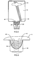
Fig. 5 is a plan view showing cut points to separate the cap from the security element and holder assembly, e.g., hang tag; -
Fig. 6 is an expanded view of the cut point area shown inFig. 5 ; -
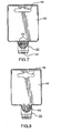
Fig. 7 is a plan view showing an embodiment of the invention in which the security element is inserted between the inward projections within the cap before the cap is attached to the container; -
Fig. 8 is a plan view showing an alternative embodiment in which the cap has a "teardrop" hole for hanging the container and cap once they have been separated as an integral unit from the security element and holder assembly, e.g., hang tag; -
Figs. 9 to 11 are views of an embodiment in which the cap has a through hole for hanging the container and cap once they have been separated as a unit from the security element and holder assembly, e.g., hang tag, in which -
Fig. 9 is a plan view thereof, -
Fig. 10 is a side view thereof, and -
Fig. 11 is a plan view in partial section; -
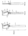
Figs. 12, 13 and 14 are views of an overall assembly including an example of a drill bit within the container, as shown inFig. 1 , in which -
Fig. 12 is a decoupled front view, -
Fig. 13 is a coupled front view, and -
Fig. 14 is a coupled side view; -
Figs. 15 to 17 are views of another embodiment of the invention in which the security element includes an integrally-molded strap between opposed sides of the cap, in which -
Fig. 15 is a side view thereof in its coupled orientation, -
Fig. 16 is a side view thereof after the strap has been cut to enable decoupling, and -
Fig. 17 is an enlarged close-up of the view ofFig. 16 ; -
Figs. 18 to 20 are views of yet another embodiment of this invention in which the security element includes a pin securing the container to the cap which is integral with the holder assembly, e.g., hang tag, in which -
Fig. 18 is a decoupled front view thereof, -
Fig. 19 is a coupled front view thereof, and -
Fig. 20 is a coupled side view thereof also showing insertion of a pin; -
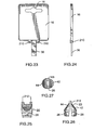
Figs. 21 to 27 are views of still another embodiment of this invention in which one portion of the security element includes protruding mushroom pins to engage the cap, and a stop member which is integral with another portion of the holder member assembly, e.g,. hang tag, of the security element, in which -
Fig. 21 is a front view of the coupled holder assembly, e.g., hang tag and cap, -
Fig. 22 is a side view of the view shown inFig. 21 , -
Fig. 23 is a front view of the holder assembly, e.g., hang tag, including the security element, -
Fig. 24 is a side view of the view shown inFig. 23 , -
Fig. 25 is a front view of the cap element, -
Fig. 26 is a side view of the cap element, and -
Fig. 27 is a bottom view of the cap element; and -
Fig. 28 and Fig. 29 are views of yet a further embodiment of the invention in which the cap is inset rather than projecting from the lower edge of the holder assembly, e.g., hang tag, in which -
Fig. 28 is a front view thereof; -
Fig. 29 is a side view thereof; and -
Fig 30 . is a perspective view showing an additional rib or tab aimed at preventing rotation of the tube. -
Fig. 1 shows one embodiment of the present invention in the form of acontainer 10 which is constituted by the form of a cylindrical tube containing aproduct 12, e.g., a drill bit, and aholder assembly 14. Theholder assembly 14 preferably is ahang tag portion 16 which preferably has ahole 18 for hanging theproduct 12 at the point-of-sale. Theholder assembly 14 also initially includes an integral projectingcap portion 20 which may be separated from the holder assembly 14 (hang tag 16) by cutting at two cut points, to be described hereinafter. - The
cap portion 20 includes aprimary portion 22 which is integral with the holder assembly 14 (hang tag 16), and a reduceddiameter portion 24. Reduceddiameter portion 24 is provided with two, diametrically-opposed integral locking ramped projections 26 (only one of which can be seen) along its outer circumference. - The
end 28 of thetube 10 is provided with two diametrically-opposedlocking openings 30. The locking rampedprojections 26 are configured to engage with the lockingopenings 30 to lock thetube 10 in place against aface 32 of the larger-diameterprimary portion 22 of thecap 20. - The
cap 20 has two diametrically-opposed, longitudinally-extendingslots 34, which can be urged to closer proximity at their open ends to permit the locking rampedprojections 26 to mate with the lockingopenings 30 in order to couple thetube 10 with thecap 20. Theseslots 34 also permit thecap 20 to be manually squeezed so that the locking rampedprojections 26 can be disengaged from the lockingopenings 30, to decouple thecap 20 from thetube 20. - Such removal of the
cap 20 from thetube 10 is prevented by a security element provided by various embodiments of this invention. One embodiment of such security element, as shown inFigs. 1 to 4 , comprises atongue 36 which projects into the interior of thecap 20 and which is integral with the holder assembly 14 (hang tag 16). Thetongue 36 is slidably disposed between two integral, inwardly-orientedprojections 38 within the interior of thecap 20. It is noted that thetongue 36 and the two internal inwardly-orientedprojections 38 have a cruciform shape. - Once the holder assembly 14 (hang tag 16) is cut away from the
cap 20 and is discarded, as shown inFig. 2 , thetongue 36 no longer is seen. In its place, is a longitudinally-extendingslot 40 between the two internal inwardly-orientedprojections 38. - In the absence of the
tongue 36, thecap 20 may be manually-squeezed to urge theslots 34 closer together at their open ends to decouple thecap 20 from thetube 10. -
Fig. 3 shows thecap 20 holder assembly 14 (hang tag 16) in its "as molded" orientation. It will be noted that thecap 20, as molded is formed of twoopen jaw parts projections 38 are also seen, as is thetongue 36 which is integral with the holder assembly 14 (hang tag 16). -
Fig. 4 is an enlarged view ofFig. 1 showing thecap 20 and the holder assembly 14 (hang tag 16) in its orientation ready to be received in thetube 10. -
Figs. 5 and 6 show the cut points to separate the holder assembly 14 (hang tag 16) from thecap 20. In this embodiment, thetongue 36 is integrally molded with the holder assembly 14 (hang tag16) and is shown projecting downwardly into thecap 20. Cutting the hang tag portion at the two spaced-apartlocations tongue 36 to be removed as a unit from thecap 20. Thecap 20 is still attached to thetube 10. However, as explained hereinabove, thecap 20 may now easily be decoupled from thetube 10 by squeezing the cap 20: -
Fig. 7 shows a second embodiment of the security element combination of this invention. In this embodiment thetongue 52 is a separate piece, which is manually-inserted into theslot 40 between the two inwardly-oriented projections 38 (SeeFig. 2 ) before thecap 20 is attached to thetube 10. In order to decouple thecap 20 from thetube 10, the holder assembly 14 (hang tag 16) can be bent at bend lines 64, and thetongue 52 can then be removed by pliers. Thecap 20 can then be squeezed and decoupled from thetube 10 as previously described. The holder assembly 14 (hang tag 16) can be retained or fully separated from thecap 20 and discarded. -
Figs. 8 to 11 show one manner in which thecap 20/tube 10 may be hung up after it is decoupled from the holder assembly 14 (hang tag 16) by the consumer. This manner is by way of either a tear-drop hole 56 (seeFig. 8 ) or a simple aperture 58 (SeeFigs. 9 and 11 ). -
Figs. 12 to 14 show views of an overall assembly of the holder assembly 14 (hang tag 16), thecap 20 and thetube 10 which includes, for example, adrill bit 12 as the article. -
Figs. 15 to 17 show another embodiment of a security element according to this invention. In this embodiment of the invention, the twoparts cap 20 being attached to thetube 10, held secure by means of an integrally-moldedstrap 150, (SeeFig.15 ). - After sale, when the
strap 150 is cut by the consumer (SeeFigs. 16 and 17 ) the twoparts cap 20 can flex to enable manually squeezing together thereof. This permits the locking rampedprojections 26 to be removed from the lockingapertures 30, and thereby permit thecap 20 to be decoupled from thetube 10. -
Figs. 18 to 20 show still another embodiment of a security element according to this invention. In this embodiment of the invention, the twoparts tube 10 is secured to thecap 20 by apin 180 passing through cooperatingholes 182 incap tube 10. Thepin 180 can be heat-staked after insertion, or flattened on both ends, to make removal at the retail site difficult. However, the flattened ends can be severed, i.e., the pin can be structurally-altered, to enable removal of thepin 180. Once thepin 180 is removed, thecap 20 andtube 10 can be decoupled. - This embodiment also shows the strap 150 (described in
Figs. 15 to 18 ). However, such strap is not essential for operation of this embodiment of the invention. -
Figs. 21 to 27 show yet still another embodiment of a security element according to this invention. In this embodiment, thecap 20 is secured to the holder assembly 14 (hang tag 16) by means of mushroom pins 210 operatively inserted into associatedholes 212. Thepins 210 may be provided either on the holder assembly 14 (hang tag 16) or in thecap 20 with theholes 212 respectively. In thecap 20 or in the holder assembly 14 (hang tag 16). As shown herein, however, thepins 210 are on the holder assembly 14 (hang tag 16), and theholes 212 are in thecap 20. - In use, the
cap 20 is placed onto thetube 10, and thetongue 36 is inserted into theslot 40 in thecap 20 between the two integral inwardly-orientedprojections 38. When the holder assembly 14 (hang tag 16) is fully seated, thepins 210 on one component are pressed through theholes 212 in the other component to complete the assembly. The mushroom head prevents removal of thepins 210 from theholes 212. This must be done by special cutters either at the point-of-sale or later by the consumer. However, once the mushroom heads are severed, thepins 210 may be removed from theholes 212, and thecap 20 can be decoupled from thetube 10. -
Figs 28 and 29 show a still further embodiment of the security element of the present invention. The holder assembly 14 (hang tag 16) is provided with aU-shaped cap 2820 which is inset from the lower edge thereof. Thecap 2820 includes aclosure element 2824. The lower ends of theU-shaped cap 2820 are provided with inwardly-facing, rampedprojections 2826. Astop tongue 2836 is integral with the holder assembly 14 (hang tag 16) and extends through theclosure element 2824. - Assembly of the holder assembly 14 (hang tag 16) is the same as the assembly of the
cap 20 andtube 10 ofFigs. 1 to 4 . - Decoupling is effected by cutting at
cut lines cap 2820 may be used as a cap for thetube 10 as described with respect toFigs. 1 to 4 . -
Fig. 30 shows a still further embodiment of the security element of the present invention. In this embodiment, thecap portion 20 hastabs 60 extending axially therefrom, which engage in correspondingslots 62 in the end of the tube (one on each side of the tube, for example). This acts as a further obstacle to prevent twisting of the tube in an attempt to separate it from the hang tag. - The main advantages of embodiments of this invention is the point-of-sale security which is provided, and the potential for the consumer subsequently to reuse the container with its cap.
- Although the accompanying drawings illustrate only a cylindrical embodiment of the container, it should be readily appreciated that the principle of the invention could be readily employed with a square, oval, rectangular or any other shape which would still permit squeezing of the cap to disengage the ramped projections. Similarly, it should be appreciated that there could be, for example in a rectangular embodiment, a number of such ramped projections along both upper and lower edges, such that squeezing the cap would disengage each of those multiple projections.
- From the foregoing description, one skilled in the art can easily ascertain the essential characteristics of this invention, and without departing from the scope thereof, can make various changes and modifications of the invention to adapt it to various usages and conditions. Consequently, such changes and modifications are properly, equitably, and "intended" to be, within the full range of equivalence of the following claims.
- The invention provides a container which it is more difficult for consumers to open without authorization at the point of sale.
Claims (23)
- A point-of-sale security system for a product (12), said system comprising:a container (10) for containing said product;a holder assembly (14), said holder assembly including a closure device (2) for closing said container and hanging means (16, 18);said holder assembly and said container being operatively coupled together by means of flexibly-movable parts (42, 44), characterized in that said flexibly-movable parts (42, 44) are configured so that:a) when an associated stop member (36, 150) is enabled, said flexibly-movable parts (42, 44) provide a rigid assembly to prevent decoupling of said holder assembly from said container, andb) when said stop member (36, 150) is disabled, said flexibly-movable parts (42, 44) enable decoupling of said holder assembly from said container.
- The point-of-sate security system as claimed in claim 1, wherein said hanging means is a hang tag (16).
- The point-of-sale security system as claimed in claim 2, wherein said closure device comprises a cap (20) which is integral with said hang tag (16).
- The point-of-sale security system as claimed in claim 3, wherein:said cap (20) includes a pair of flexibly-movable parts (42, 44);said hang tag (16) is integrally associated with said stop member (36; 150); andsaid hang tag is configured to be severed, along with its stop member, from said cap and to be discarded;thereby disabling said stop member and permitting said cap to be decoupled from said container (10).
- The point-of-sate security system as claimed in claim 4, wherein said cap (20) includes a pair of slits (34) to enable flexing of said two associated flexibly-movable parts (42, 44) of said cap, thereby to urge movement of said slits towards one another at their open ends, to enable decoupling of said cap from said container (10).
- The point-of-sale security system as claimed in claim 5, wherein
said cap (20) is provided with at least two external locking ramped projections (26); and
said container (10) is provided with a like number of cooperating locking apertures (30), whereby said cap and said container may be selectively coupled and decoupled. - The point-of-sale security system as claimed in claim 6, wherein:said stop member is a tongue (36) projecting from said hang tag (16); andsaid tongue is slidably disposed within a longitudinal slot (40) between two opposed integral, internally-oriented projections (38) within the interior of said cap (20).
- The point-of-sate security system as claimed in claim 3, wherein
said cap (20) comprises two flexibly-movable parts (42, 44) which are held in position by at least one integrally-molded strap (150); and
said at least one integrally-molded strap comprising said stop member:
whereby, when said at least one strap is severed, said two parts of said cap may be urged towards one another, thereby enabling decoupling of said cap from said container. - The point-of-sate security system as claimed in claim 8, wherein
said cap (20) is provided with at least two external locking ramped projections (26); and
said container (10) is provided with a like number of cooperating locking apertures (30),
whereby said cap and said container may be selectively coupled and decoupled. - The point-of-sate security system as claimed in claim 3, wherein
said cap (20) comprises two flexibly-movable parts (42, 44); and
said flexibly-movable parts are held in position, and said cap is secured to said container (10), by means of a pin (180) passing through cooperating aligned apertures (182, 184) in said cap and said container, said pin being secured in said apertures;
whereby, said pin is structurally altered to enable decoupling of said cap from said container. - The point-of-sate security system as claimed in claim 10, wherein said two flexibly-movable parts (42, 44) of said cap (20) are also held in position by severable, hitegrally-molded straps.
- The point-of-sale security system as claimed in claim 10, wherein:said cap (20) is provided with at least two external locking ramped projections (26); andsaid container (10) is provided with a like number of cooperating locking apertures (30),whereby said cap and said container may be selectively coupled and decoupled.
- The point-of-sale security system as claimed in claim 3, wherein:said cap (20) includes a pair of flexibly-movable parts (42, 44);said hang tag (16) is integrally associated with said stop member (36); andsaid cap is secured to said hang tag by means of mushroom pins(210) and cooperating apertures (212) which are operatively associated with said hang tag and said cap;whereby, when said mushroom pins are structurally-altered to enable removal from said apertures, the two parts of said capmay, after removal of said stop member (36), be urged towards one another to enable decoupling of said cap and said container.
- The point-of-sate security system as claimed in claim 13, wherein:said cap (20) is provided with at least two external locking projections (26); andsaid container (10) is provided with a like number of cooperating locking apertures (30), whereby said cap and said container may be selectively coupled and decoupled.
- The point-of-sale security system as claimed in claim 14, wherein:said stop member is a tongue (36) projecting from said hang tag; andsaid tongue is slidably disposed within a longitudinal slot (40) between two opposed internal, inwardly-oriented projections (38) within the interior of said cap.
- The point-of-sale security system as claimed in claim 1, wherein:said cap includes an integral cap (2820) which is inset within a lower edge of said hang tag (16);said hang tag is integrally associated with said stop member (2836); andsaid hang tag is configured to be severed, along with its stop member, from said cap and to be discarded;thereby disabling said stop member and permitting said cap to be decoupled from said container (10).
- The point-of-sale security system as claimed in claim 16, wherein:said cap (2820) is provided with at least two external locking ramped projections (2826); andsaid container (10) is provided with a like number of cooperating locking apertures (30);whereby said cap and said container may be selectively coupled and decoupled.
- The point-of-sale security system as claimed in claim 17, wherein:said stop member is a tongue (2836) projecting from said hang tag (16); andsaid tongue is slidably disposed within a longitudinal slot between two opposed internal, inwardly-oriented projections within the interior of said cap.
- The point-of-sale security system as claimed in claim 1, wherein said holder assembly has at least one tab (60) extending axially therefrom, each said tab engaging in a corresponding slot (62) in said container (10) to prevent the container from rotating about its axis while attached to said holder.
- The point-of-sale security system as claimed in claim 1 wherein said closure device is a cap (20).
- The point-of-sale security device as claimed in claim 22 wherein said cap (20) and said container (10) are coupled together to form a container assembly.
- The point-of-sals security system as claimed in claim 23 wherein said stop member is integral with said container assembly.
- The point-of-sale security system as claimed in claim 23 wherein said stop member is integral with said cap.
Applications Claiming Priority (3)
| Application Number | Priority Date | Filing Date | Title |
|---|---|---|---|
| US31108401P | 2001-08-10 | 2001-08-10 | |
| US311084P | 2001-08-10 | ||
| PCT/CA2002/001232 WO2003013971A1 (en) | 2001-08-10 | 2002-08-08 | Product holder with point-of-sale security |
Publications (2)
| Publication Number | Publication Date |
|---|---|
| EP1417136A1 EP1417136A1 (en) | 2004-05-12 |
| EP1417136B1 true EP1417136B1 (en) | 2008-06-25 |
Family
ID=23205324
Family Applications (1)
| Application Number | Title | Priority Date | Filing Date |
|---|---|---|---|
| EP02754013A Expired - Lifetime EP1417136B1 (en) | 2001-08-10 | 2002-08-08 | Product holder with point-of-sale security |
Country Status (5)
| Country | Link |
|---|---|
| US (2) | US6854594B2 (en) |
| EP (1) | EP1417136B1 (en) |
| AT (1) | ATE399133T1 (en) |
| DE (1) | DE60227261D1 (en) |
| WO (1) | WO2003013971A1 (en) |
Families Citing this family (38)
| Publication number | Priority date | Publication date | Assignee | Title |
|---|---|---|---|---|
| US7111422B2 (en) * | 2003-04-29 | 2006-09-26 | Jpj Investment Holding Corp. | Hangtag for multiple tools |
| US7121031B2 (en) * | 2003-06-10 | 2006-10-17 | Olympia Group, Inc. | Hangtag with tool securing mechanism |
| USD520875S1 (en) | 2003-06-10 | 2006-05-16 | Olympia Group, Inc. | Hangtag |
| US7210663B2 (en) * | 2003-06-17 | 2007-05-01 | Jpj Investment Holding Corporation | Tool securing mechanism for hangtag assembly |
| US20040256262A1 (en) * | 2003-06-17 | 2004-12-23 | Wheeler Thomas J. | Tool securing mechanism for hangtag assembly |
| FR2862618B1 (en) * | 2003-11-24 | 2007-04-13 | Pierre Malek | TOOL DISCHARGE TOOL STORAGE DEVICE |
| US20050126943A1 (en) * | 2003-12-16 | 2005-06-16 | Liu Yung Y. | Hanging card mechanism for a socket |
| DE102005003416B4 (en) * | 2004-04-01 | 2013-09-12 | Peter Rösler | Hanger for drills |
| WO2005097602A2 (en) * | 2004-04-05 | 2005-10-20 | Loctite (R & D) Limited | A container and combination packaging |
| US20050230587A1 (en) * | 2004-04-16 | 2005-10-20 | Yang Hsiu C | Display device for article for sale |
| US7175151B2 (en) * | 2005-03-22 | 2007-02-13 | Chi-Tsai Chang | Hand tool suspension device |
| DE202005007586U1 (en) * | 2005-05-13 | 2005-08-04 | Rösler, Peter | Container with locking connection for receiving heavy objects has locking connection between upper and lower parts consisting of locking tongues and slots |
| US7264213B2 (en) * | 2005-08-11 | 2007-09-04 | Yung Yuan Liu | Hanging device for tool |
| US20070193313A1 (en) * | 2006-02-21 | 2007-08-23 | Yu-Chi Tsai | Anti-theft tag |
| US20090023328A1 (en) * | 2007-07-16 | 2009-01-22 | Tsung-Da Lin | Burglarproof socket exhibition assembly |
| US7841468B2 (en) * | 2007-11-08 | 2010-11-30 | Robert Bosch Gmbh | Accessory holder |
| US20110108553A1 (en) * | 2009-11-11 | 2011-05-12 | Pantelleria Joseph A | Container/lid assembly |
| TWM385264U (en) * | 2010-02-11 | 2010-08-01 | ji-cai Zhang | Safety hanging structure for tool box |
| US8690400B2 (en) | 2011-06-29 | 2014-04-08 | Target Brands, Inc. | Holding structure for light socket |
| US8381905B1 (en) * | 2011-11-18 | 2013-02-26 | Jui-Chien Kao | Burglarproof bit socket bracket assembly |
| US8443972B1 (en) | 2011-12-23 | 2013-05-21 | Robert Bosch Gmbh | Hang tag assembly for a hole saw |
| US20130180878A1 (en) * | 2012-01-18 | 2013-07-18 | Maxtech Consumer Products Limited | Plastic packaging, and method and apparatus for producing same |
| TWM439552U (en) * | 2012-05-28 | 2012-10-21 | Ming-Hong Lin | Tool hanging card |
| TWM449072U (en) * | 2012-09-21 | 2013-03-21 | Chun Nien Plastic Led | Anti-theft safety hanging member |
| US8567220B1 (en) | 2013-02-26 | 2013-10-29 | Hamid Mchatet | Magnetic lock assembly |
| US8667818B1 (en) | 2013-07-11 | 2014-03-11 | Hamid Mchatet | Packaging lock assembly |
| US9078532B1 (en) | 2014-01-07 | 2015-07-14 | Hamid Mchatet | Circular lock assembly |
| US9289080B1 (en) | 2014-05-13 | 2016-03-22 | Hamid Mchatet | Rail assembly lock |
| US10315819B2 (en) * | 2016-04-24 | 2019-06-11 | Li-Tang Jhu | Tool display device |
| US10000322B2 (en) * | 2016-06-30 | 2018-06-19 | Robert Bosch Gmbh | Hang tag for displaying an object |
| US20180370697A1 (en) * | 2017-06-23 | 2018-12-27 | Jared Koett | Closed container system |
| WO2020257072A1 (en) | 2019-06-17 | 2020-12-24 | Milwaukee Electric Tool Corporation | Drill bit packaging |
| US12006084B2 (en) | 2021-03-18 | 2024-06-11 | Milwaukee Electric Tool Corporation | Drill bit packaging |
| KR102733145B1 (en) * | 2022-04-05 | 2024-11-25 | 주식회사 삼에스코리아 | Wafer container and cap assembly used therefor |
| EP4311793B1 (en) * | 2022-07-27 | 2024-05-22 | Hilti Aktiengesellschaft | Merchandise hanger, sales product and method of manufacture |
| GB2634495B (en) * | 2023-10-03 | 2026-01-07 | Coral Tools Ltd | Improvements in or relating to paint roller tube packaging |
| PL447593A1 (en) * | 2024-01-23 | 2025-07-28 | Chudy Joanna Mgr Inż. Joanna Chudy Glas Hit Eksport Import | Tool element hanger |
| GB2641533A (en) * | 2024-06-04 | 2025-12-10 | Coral Tools Ltd | Improvements in or relating to paint roller tube packaging |
Family Cites Families (18)
| Publication number | Priority date | Publication date | Assignee | Title |
|---|---|---|---|---|
| US3023925A (en) * | 1959-09-21 | 1962-03-06 | Fred D Sher | Container for packaging merchandise |
| US3703975A (en) * | 1970-06-19 | 1972-11-28 | William C Wittemer | Safety closure |
| US4378068A (en) * | 1981-05-07 | 1983-03-29 | Container Corporation Of America | Composite carded display package with cover |
| US4480762A (en) * | 1982-06-11 | 1984-11-06 | Ryder International Corporation | Reuseable vial cap |
| US4445622A (en) * | 1982-07-09 | 1984-05-01 | Leonardo Sideri | Self-locking pilfer proof container |
| US4712671A (en) * | 1986-05-27 | 1987-12-15 | Salacuse Frank S | Universal hanging packaging system |
| US5386918A (en) | 1993-04-22 | 1995-02-07 | Colgate-Palmolive Co. | Closure with tamper evidence structure |
| US5356044A (en) | 1993-09-10 | 1994-10-18 | Polytop Corporation | Tamper evident seal for dispensing closure |
| US5373953A (en) * | 1994-02-17 | 1994-12-20 | Fenton; Russell R. | Display mounting cap for containers |
| US5799840A (en) | 1996-04-25 | 1998-09-01 | Tetra Laval Holdings & Finance, S A | Closure formed as a single, integral part |
| US5979649A (en) * | 1997-02-28 | 1999-11-09 | Rose Plastic Gmbh | Elongated packing container for an elongated object |
| US5740911A (en) * | 1997-04-10 | 1998-04-21 | Chou; Ta-Ching | Display pack having a security device |
| US5988413A (en) * | 1997-06-18 | 1999-11-23 | Jsn Product Concepts, Inc. | Child resistant container and closure |
| US5875902A (en) | 1997-12-03 | 1999-03-02 | Better Sleep Mfg., Co. | Locking means for over-the-door shelf |
| US5918752A (en) * | 1998-01-14 | 1999-07-06 | Owens-Illinois Closure Inc. | Tamper-evident squeeze-and-turn child-resistant closure |
| US6321944B1 (en) | 1998-05-29 | 2001-11-27 | Edward M. Cetrangolo | Display apparatus for a collapsible tube dispenser |
| DE19901295A1 (en) | 1999-01-15 | 2000-07-20 | Zeiss Carl Fa | Optical imaging device, in particular objective, with at least one optical element |
| US6662948B1 (en) * | 2001-10-04 | 2003-12-16 | Stephen P. Velliquette | Retail display hang tag device |
-
2002
- 2002-08-08 AT AT02754013T patent/ATE399133T1/en not_active IP Right Cessation
- 2002-08-08 EP EP02754013A patent/EP1417136B1/en not_active Expired - Lifetime
- 2002-08-08 WO PCT/CA2002/001232 patent/WO2003013971A1/en not_active Ceased
- 2002-08-08 DE DE60227261T patent/DE60227261D1/en not_active Expired - Lifetime
- 2002-08-09 US US10/214,589 patent/US6854594B2/en not_active Expired - Fee Related
-
2005
- 2005-01-26 US US11/042,198 patent/US20050126933A1/en not_active Abandoned
Also Published As
| Publication number | Publication date |
|---|---|
| ATE399133T1 (en) | 2008-07-15 |
| US6854594B2 (en) | 2005-02-15 |
| US20030029756A1 (en) | 2003-02-13 |
| EP1417136A1 (en) | 2004-05-12 |
| DE60227261D1 (en) | 2008-08-07 |
| WO2003013971A1 (en) | 2003-02-20 |
| US20050126933A1 (en) | 2005-06-16 |
Similar Documents
| Publication | Publication Date | Title |
|---|---|---|
| US6854594B2 (en) | Product holder with point-of-sale security | |
| US6206189B1 (en) | Display container having secure closure mechanism | |
| JP2793368B2 (en) | Thermoplastic safety seal | |
| US9975682B2 (en) | Jewelry display hanger with security tag | |
| US4378068A (en) | Composite carded display package with cover | |
| US5791079A (en) | Multi-purpose tag for irreversible fixing to objects displayed for sale | |
| US6463696B2 (en) | Container and tag assembly | |
| US5291996A (en) | Reusable display sheath with frangible latch means | |
| US5918741A (en) | Tool case | |
| US4514882A (en) | Device for retaining in side-by-side relationship flexible tying means such as shoelaces | |
| US7624865B2 (en) | Specialty product hang tag | |
| US20190099015A1 (en) | Earring security display hanger | |
| EP0921513B1 (en) | Sealing device | |
| US10631669B2 (en) | Necklace security display hanger | |
| US11745924B2 (en) | Saw blade holder | |
| US9637273B2 (en) | Hang tag package for a saw blade | |
| JPH0823364B2 (en) | Clip | |
| EP2169158B1 (en) | Disposable anti-theft device for eyeglasses | |
| EP4420999A1 (en) | Wiper blade packaging | |
| CN117957172B (en) | Components for storing and displaying personal care products | |
| EP0761561B1 (en) | Hanger | |
| GB2413315A (en) | Container having an opening means | |
| JP3076867U (en) | Packaging tools | |
| JPH0661772U (en) | Carrying case | |
| CN108496208A (en) | Point of sale component with anti-theft feature and its method |
Legal Events
| Date | Code | Title | Description |
|---|---|---|---|
| PUAI | Public reference made under article 153(3) epc to a published international application that has entered the european phase |
Free format text: ORIGINAL CODE: 0009012 |
|
| 17P | Request for examination filed |
Effective date: 20040304 |
|
| AK | Designated contracting states |
Kind code of ref document: A1 Designated state(s): AT BE BG CH CY CZ DE DK EE ES FI FR GB GR IE IT LI LU MC NL PT SE SK TR |
|
| AX | Request for extension of the european patent |
Extension state: AL LT LV MK RO SI |
|
| GRAP | Despatch of communication of intention to grant a patent |
Free format text: ORIGINAL CODE: EPIDOSNIGR1 |
|
| GRAS | Grant fee paid |
Free format text: ORIGINAL CODE: EPIDOSNIGR3 |
|
| GRAA | (expected) grant |
Free format text: ORIGINAL CODE: 0009210 |
|
| AK | Designated contracting states |
Kind code of ref document: B1 Designated state(s): AT BE BG CH CY CZ DE DK EE ES FI FR GB GR IE IT LI LU MC NL PT SE SK TR |
|
| REG | Reference to a national code |
Ref country code: GB Ref legal event code: FG4D |
|
| REG | Reference to a national code |
Ref country code: CH Ref legal event code: EP |
|
| REF | Corresponds to: |
Ref document number: 60227261 Country of ref document: DE Date of ref document: 20080807 Kind code of ref document: P |
|
| REG | Reference to a national code |
Ref country code: IE Ref legal event code: FG4D |
|
| PG25 | Lapsed in a contracting state [announced via postgrant information from national office to epo] |
Ref country code: FI Free format text: LAPSE BECAUSE OF FAILURE TO SUBMIT A TRANSLATION OF THE DESCRIPTION OR TO PAY THE FEE WITHIN THE PRESCRIBED TIME-LIMIT Effective date: 20080625 |
|
| PG25 | Lapsed in a contracting state [announced via postgrant information from national office to epo] |
Ref country code: NL Free format text: LAPSE BECAUSE OF FAILURE TO SUBMIT A TRANSLATION OF THE DESCRIPTION OR TO PAY THE FEE WITHIN THE PRESCRIBED TIME-LIMIT Effective date: 20080625 Ref country code: AT Free format text: LAPSE BECAUSE OF FAILURE TO SUBMIT A TRANSLATION OF THE DESCRIPTION OR TO PAY THE FEE WITHIN THE PRESCRIBED TIME-LIMIT Effective date: 20080625 |
|
| NLV1 | Nl: lapsed or annulled due to failure to fulfill the requirements of art. 29p and 29m of the patents act | ||
| PG25 | Lapsed in a contracting state [announced via postgrant information from national office to epo] |
Ref country code: CZ Free format text: LAPSE BECAUSE OF FAILURE TO SUBMIT A TRANSLATION OF THE DESCRIPTION OR TO PAY THE FEE WITHIN THE PRESCRIBED TIME-LIMIT Effective date: 20080625 Ref country code: SE Free format text: LAPSE BECAUSE OF FAILURE TO SUBMIT A TRANSLATION OF THE DESCRIPTION OR TO PAY THE FEE WITHIN THE PRESCRIBED TIME-LIMIT Effective date: 20080925 Ref country code: PT Free format text: LAPSE BECAUSE OF FAILURE TO SUBMIT A TRANSLATION OF THE DESCRIPTION OR TO PAY THE FEE WITHIN THE PRESCRIBED TIME-LIMIT Effective date: 20081125 Ref country code: ES Free format text: LAPSE BECAUSE OF FAILURE TO SUBMIT A TRANSLATION OF THE DESCRIPTION OR TO PAY THE FEE WITHIN THE PRESCRIBED TIME-LIMIT Effective date: 20081006 |
|
| PG25 | Lapsed in a contracting state [announced via postgrant information from national office to epo] |
Ref country code: BE Free format text: LAPSE BECAUSE OF FAILURE TO SUBMIT A TRANSLATION OF THE DESCRIPTION OR TO PAY THE FEE WITHIN THE PRESCRIBED TIME-LIMIT Effective date: 20080625 Ref country code: SK Free format text: LAPSE BECAUSE OF FAILURE TO SUBMIT A TRANSLATION OF THE DESCRIPTION OR TO PAY THE FEE WITHIN THE PRESCRIBED TIME-LIMIT Effective date: 20080625 |
|
| PG25 | Lapsed in a contracting state [announced via postgrant information from national office to epo] |
Ref country code: MC Free format text: LAPSE BECAUSE OF NON-PAYMENT OF DUE FEES Effective date: 20080831 |
|
| REG | Reference to a national code |
Ref country code: CH Ref legal event code: PL |
|
| PG25 | Lapsed in a contracting state [announced via postgrant information from national office to epo] |
Ref country code: EE Free format text: LAPSE BECAUSE OF FAILURE TO SUBMIT A TRANSLATION OF THE DESCRIPTION OR TO PAY THE FEE WITHIN THE PRESCRIBED TIME-LIMIT Effective date: 20080625 Ref country code: DK Free format text: LAPSE BECAUSE OF FAILURE TO SUBMIT A TRANSLATION OF THE DESCRIPTION OR TO PAY THE FEE WITHIN THE PRESCRIBED TIME-LIMIT Effective date: 20080625 Ref country code: BG Free format text: LAPSE BECAUSE OF FAILURE TO SUBMIT A TRANSLATION OF THE DESCRIPTION OR TO PAY THE FEE WITHIN THE PRESCRIBED TIME-LIMIT Effective date: 20080925 |
|
| PLBE | No opposition filed within time limit |
Free format text: ORIGINAL CODE: 0009261 |
|
| STAA | Information on the status of an ep patent application or granted ep patent |
Free format text: STATUS: NO OPPOSITION FILED WITHIN TIME LIMIT |
|
| GBPC | Gb: european patent ceased through non-payment of renewal fee |
Effective date: 20080925 |
|
| REG | Reference to a national code |
Ref country code: IE Ref legal event code: MM4A |
|
| 26N | No opposition filed |
Effective date: 20090326 |
|
| PG25 | Lapsed in a contracting state [announced via postgrant information from national office to epo] |
Ref country code: CH Free format text: LAPSE BECAUSE OF NON-PAYMENT OF DUE FEES Effective date: 20080831 Ref country code: LI Free format text: LAPSE BECAUSE OF NON-PAYMENT OF DUE FEES Effective date: 20080831 |
|
| PG25 | Lapsed in a contracting state [announced via postgrant information from national office to epo] |
Ref country code: IE Free format text: LAPSE BECAUSE OF NON-PAYMENT OF DUE FEES Effective date: 20080808 |
|
| PG25 | Lapsed in a contracting state [announced via postgrant information from national office to epo] |
Ref country code: IT Free format text: LAPSE BECAUSE OF FAILURE TO SUBMIT A TRANSLATION OF THE DESCRIPTION OR TO PAY THE FEE WITHIN THE PRESCRIBED TIME-LIMIT Effective date: 20080625 |
|
| PG25 | Lapsed in a contracting state [announced via postgrant information from national office to epo] |
Ref country code: GB Free format text: LAPSE BECAUSE OF NON-PAYMENT OF DUE FEES Effective date: 20080925 |
|
| PG25 | Lapsed in a contracting state [announced via postgrant information from national office to epo] |
Ref country code: CY Free format text: LAPSE BECAUSE OF FAILURE TO SUBMIT A TRANSLATION OF THE DESCRIPTION OR TO PAY THE FEE WITHIN THE PRESCRIBED TIME-LIMIT Effective date: 20080625 Ref country code: LU Free format text: LAPSE BECAUSE OF NON-PAYMENT OF DUE FEES Effective date: 20080808 |
|
| PG25 | Lapsed in a contracting state [announced via postgrant information from national office to epo] |
Ref country code: TR Free format text: LAPSE BECAUSE OF FAILURE TO SUBMIT A TRANSLATION OF THE DESCRIPTION OR TO PAY THE FEE WITHIN THE PRESCRIBED TIME-LIMIT Effective date: 20080625 |
|
| PG25 | Lapsed in a contracting state [announced via postgrant information from national office to epo] |
Ref country code: GR Free format text: LAPSE BECAUSE OF FAILURE TO SUBMIT A TRANSLATION OF THE DESCRIPTION OR TO PAY THE FEE WITHIN THE PRESCRIBED TIME-LIMIT Effective date: 20080926 |
|
| PGFP | Annual fee paid to national office [announced via postgrant information from national office to epo] |
Ref country code: DE Payment date: 20101015 Year of fee payment: 9 |
|
| PGFP | Annual fee paid to national office [announced via postgrant information from national office to epo] |
Ref country code: FR Payment date: 20110922 Year of fee payment: 10 |
|
| REG | Reference to a national code |
Ref country code: FR Ref legal event code: ST Effective date: 20130430 |
|
| PG25 | Lapsed in a contracting state [announced via postgrant information from national office to epo] |
Ref country code: DE Free format text: LAPSE BECAUSE OF NON-PAYMENT OF DUE FEES Effective date: 20130301 |
|
| PG25 | Lapsed in a contracting state [announced via postgrant information from national office to epo] |
Ref country code: FR Free format text: LAPSE BECAUSE OF NON-PAYMENT OF DUE FEES Effective date: 20120831 |
|
| REG | Reference to a national code |
Ref country code: DE Ref legal event code: R119 Ref document number: 60227261 Country of ref document: DE Effective date: 20130301 |