BACKGROUND OF THE INVENTION
1. Field of the Invention
The present invention relates to an optical
transmission systems comprising a plurality of optical
amplification relay sections connected in series.
2. Description of Related Art
In recent years, data communications represented
by the Internet are showing a rapidly increasing demand.
Along with it, research and development for achieving ultra
long haul and ultra high capacity communications are being
vigorously pursued. To achieve this type of optical
networks, an optical amplifier, which is a component of an
optical transmission line, is required to reduce noise,
loss of an optical fiber, and nonlinear optical effects in
the optical fiber.
To resolve these problems and to achieve next-generation
40 Gb/s ultra high speed optical transmission
systems, a Raman effects optical fiber amplifier
(hereinafter, referred to as Raman amplifier) has been a
focus of attention. The Raman amplifier sends a pumping
light to an optical fiber, which is a transmission line, to
use the optical fiber as both of a transmission line and an
amplifier. Therefore, the Raman amplifier is possible to
increase the minimum loss level on the transmission line.
Thereby, deterioration of a signal-to-noise ratio (SN
ratio) can be inhibited.
An actual optical transmission line preferably
keeps its transmission quality without deterioration
thereof caused by a change with time (an increase of
optical fiber loss, an optical amplifier failure, etc.).
The Raman amplifier, however, permits an extremely high
input level at which a signal light gain is saturated and
therefore it is almost always running with a desaturated
gain at normal input levels of the optical communication
system. Accordingly, it has a problem of being susceptible
to deterioration with time or the like. More specifically,
if an input signal level is low, an output signal level is
low, too. If the input signal level is high, the output
signal level is high, too. Therefore, a fluctuation of the
input signal level is directly reflected on the output
signal level.
SUMMARY OF THE INVENTION
It is an object of the present invention to
provide optical transmission systems capable of keeping
stable qualities from deteriorating with time as well as
utilizing advantages of the Raman amplifier.
According to an aspect of the present invention,
there is provided an optical transmission system comprising
a plurality of optical amplification relay sections
connected in series, the optical amplification relay
sections comprising a plurality of first optical
amplification relay sections with Raman amplifiers and a
single second optical amplification relay section with an
optical fiber amplifier in a subsequent stage of the first
optical amplification relay sections. The optical
amplification relay section is defined as a section
comprising a pair of optical amplifiers and a transmission
line.
According to another aspect of the present
invention, there is provided an optical transmission system
comprising a plurality of optical amplification relay
sections connected in series, the optical amplification
relay sections comprising N (N is 2 or a greater integer)
first optical amplification relay sections with Raman
amplifiers and a single second optical amplification relay
section with an optical fiber amplifier in a subsequent
stage of the first optical amplification relay sections.
Therefore, the single second optical amplification relay
section is disposed in the subsequent stage of the N first
optical amplification relay sections.
As set forth in the above, the Raman amplifier
operates at an input signal level where a pumping gain is
constant. Therefore, if the input signal level is low, the
output signal level is low, too, while if the input signal
level is high, the output signal level is high, too. In
other words, the output signal of the Raman amplifier
reflects a fluctuation of the input signal level directly.
Thereby, a signal level having passed through the plurality
of or N first optical amplification relay sections reflects
accumulated errors in each Raman amplifier or a level
fluctuation that has occurred halfway. Therefore, it is
likely to cause a value to depart significantly from a
preset value. Therefore, the single second optical
amplification relay section is disposed in the subsequent
stage of the plurality of or N first optical amplification
relay sections. The optical fiber amplifier of the second
optical amplification relay section operates so that the
output signal level becomes constant. Therefore, the
output signal level returns to the constant value, namely,
the setting value, independently of whether the input
signal level is low or high.
BRIEF DESCRIPTION OF THE DRAWINGS
The above and other objects, features and
advantages of the present invention will become more
apparent from the following detailed description when taken
in conjunction with the accompanying drawings wherein:
DETAILED DESCRIPTION OF THE PREFERRED EMBODIMENTS
A basic configuration of an optical transmission
systems according to the present invention and its
principle of operation will now be described hereinafter.
Referring to Fig. 1, there is shown an embodiment
of an optical transmission system according to the present
invention: Fig. 1(a) is a block diagram showing an outline,
Fig. 1(b) is a schematic of a Raman optical fiber amplifier,
and Fig. 1(c) is a schematic of an optical fiber amplifier.
The preferred embodiment will now be described hereinafter
by referring to these drawings. The description will be
made by giving an example of an Erbium-doped optical fiber
amplifier (hereinafter, referred to as EDFA) as the optical
fiber amplifier. Erbium (Er) has a transition for a
wavelength 1.55 µm region that is the minimum transmission
loss in a normal single mode optical fiber. Therefore, it
is suitable for amplifying a signal light transmitted at a
low loss particularly in a long-distance transmission.
Hereinafter, the optical relay section with the
Raman amplifier is referred to as Raman amplification relay
section and the optical relay section with the EDFA doped
with Erbium as rare earth is referred to as EDFA relay
section. The optical transmission system 10 according to
this embodiment comprises Raman amplification relay
sections 11 to 1N and an EDFA relay section 21. Assuming
that N is 2 or a greater integer, the single EDFA relay
section 21 is disposed in the subsequent stage of the N
Raman amplification relay sections 11 to 1N.
In the optical transmission system 10, the total
length of the optical transmission line is formed by a
repetition of a basic block unit 30 comprising the N Raman
amplification relay sections 11 to 1N and the EDFA relay
section 21. This structure enables the optical
transmission line to be suitable for the ultra long haul
optical transmission system. Note that, however, N for the
repeated basic block unit 30 is not necessarily fixed. A
composition ratio of the Raman amplification relay sections
11 to 1N to the EDFA relay section 21 is preferably 3 or
greater to 1, more preferably 4 or greater to 1, and most
preferably 5 or greater to 1. In other words, N is
preferably 3 or greater, more preferably 4 or greater, and
most preferably 5 or greater. By way of example, an
arrangement of a single rare-earth-elements-doped optical
fiber amplifier (hereinafter, referred to as an optical
fiber amplifier) combined with only one Raman amplifier is
disclosed in the following patent document 1:
Patent document 1: Japanese Unexamined Patent Publication
(Kokai) No. Hei 11-84440 (Fig. 7 and Fig. 5).
As N is smaller, however, the number of the Raman
amplification relay sections 11 to 1N decreases, thereby a
waveform distortion or the like is caused by the EDFA.
In addition, note that the technology disclosed in
the patent document 1 is for enabling a broadband
amplification by combining the Raman amplifier with the
optical fiber amplifier and not for compensating for power
variation.
Since the respective Raman amplification relay
sections 11 to 1N have the same configuration, the Raman
amplification relay section 11 will be described here. The
Raman amplification relay section 11 comprises an optical
fiber 111 and a Raman amplifier 115. The Raman amplifier
115 comprises a wavelength division multiplexing (WDM)
coupler 112, a pumping light source 113, and an optical
isolator 114. The optical fiber 111 is a combined fiber
made by combining a positive dispersion fiber having a
positive wavelength dispersion and a dispersion slope with
a negative dispersion fiber having a negative wavelength
dispersion and a dispersion slope. Instead of the combined
fiber, a normal single mode fiber or a dispersion shifted
fiber (DSF) can be used, too. The pumping light source 113
uses 4 wavelengths (for example, 1,424 nm, 1,437 nm, 1,449
nm, and 1,465 nm) of semiconductor lasers in a bundle to
secure gain flatness. A pumping light 116 output from the
pumping light source 113 is emitted in a reverse direction
to the signal light 31. As the WDM coupler 112, for
example, a fused type WDM coupler is used. The optical
isolator 114 having a return loss more than or equal to 40
dB is used. Power of the pumping light 116 is feedback-controlled
so as to be constantly uniform. In this manner,
the pumping gain of the Raman amplifier is controlled so as
to be constant. While a counter-propagating pumping type
is described in this embodiment, a co-propagating pumping
type or a co-propagating and counter-propagating pumping
type can also be used. Since a general operation of the
Raman amplifier 115 is already known, the description will
be omitted here.
The EDFA relay section 21 comprises an optical
fiber 211 and an EDFA 217. The EDFA 217 comprises optical
isolators 212 and 216, a pumping light source 213, a WDM
coupler 214, and an amplification optical fiber 215. The
optical fiber 211 to be used is the same as, for example,
the optical fiber 111. A pumping light 218 output from the
pumping light source 213 is emitted in the same direction
as of the signal light 31. The amplification optical fiber
215 is an Erbium-doped optical fiber (EDF). The pumping
light 218 is controlled so as to maintain its output power
uniformly. The power of the pumping light 218 may be
feedback-controlled so as to be constantly uniform. In
addition, while the co-propagating pumping type is
described in this embodiment, a counter-propagating pumping
type or a co-propagating and counter-propagating pumping
type can be used, too. A general operation of the EDFA 217
is already known and therefore the description will be
omitted here.
Referring to Fig. 2, there is shown a graph of an
operational comparison of the Raman amplifier in Fig. 1 and
the EDFA (a control of pumping light power uniformity).
Fig. 2(a) shows pumping gains of the respective amplifiers
at input signal levels. Fig. 2(b) shows output signal
levels of the respective amplifiers at input signal levels.
In Fig. 2, the operations of the Raman amplifier and the
EDFA are indicated by a solid line and a dashed line,
respectively. Hereinafter, they are described by referring
to Fig. 1 and Fig. 2.
In Fig. 2(a), an abscissa axis represents input
signal levels, while an ordinate axis represents pumping
gains of the respective amplifiers. In the input signal
levels on the abscissa axis, a value of the Raman amplifier
115 equals a value obtained by subtracting a loss of the
optical transmission line from the fiber input signal level.
In the pumping gains on the ordinate axis, a value of the
Raman amplifier 115 equals a value obtained by subtracting
a loss of the optical transmission line from a net gain.
In the Raman amplifier 115, a loss and a gain occur
simultaneously on the optical transmission line, thereby
requiring the above definition.
In Fig. 2(b), the abscissa axis represents input
signal levels, while the ordinate axis represents output
signal levels of the respective amplifiers. It shows an
operating condition with a 10dB pumping gain (Output signal
level from the amplifier: 0 dBm) where the input signal
level is -10 dBm assuming a 10dB loss of the optical
transmission line. Under these operating conditions, the
Raman amplifier 115 operates with an almost uniform gain,
while the EDFA 217 for the control of pumping light power
uniformity operates with a uniform output signal level.
In this connection, consider that the input signal
level has decreased by 5 dB. The EDFA 217 for the control
of pumping light power uniformity shows an increase of the
pumping gain together with the decrease of the input signal
level (Fig. 2(a)). As a result, the output signal level
gets constant (Fig. 2(b)).
The Raman amplifier 115, however, shows a uniform
gain and keeps 10 dB (Fig. 2(a)). As a result, the output
signal level decreases to -5 dBm (Fig. 2(b)). It indicates
that, if a level fluctuation such as a loss increase occurs
in the optical transmission line, the output signal level
is corrected to the initial setting level in the EDFA relay
section 21 and the output signal level varies according to
the fluctuation in the Raman amplification relay sections
11 to 1N.
Referring to Fig. 3, there is shown a graph of
power variation at respective transmission distances in the
optical transmission system according to the present
invention. In this embodiment, there is given an example
of a case where the composition ratio of the Raman
amplification relay sections to the EDFA relay section 21
is 4 to 1. Hereinafter, the embodiment is described by
referring to Fig. 1 to Fig. 3.
It is assumed that each section input signal level
is -10 dBm, a loss in the transmission line per section is
10 dB, and a pumping gain in each section is 10 dB. Fig.
3(a) shows a normal operation. The Raman amplifier 115
outputs the pumping light 116 in the reverse direction to
the signal light 31 to amplify the light with the optical
fiber 111 that is the optical transmission line. Thereby,
the signal levels in the Raman amplification relay sections
11 to 14 and 15 are gradually attenuated according to the
distance, gradually recover upon reaching the minimum value,
and return to the initial level just before each Raman
amplifier 115. On the other hand, the signal level in the
EDFA relay section 21 is gradually attenuated according to
the distance and sharply returns to the initial level just
behind the EDFA 217 upon reaching the minimum value. It is
because, in the case of the EDFA 217, the pumping light 218
is output to the amplification optical fiber 215 and the
light is amplified only in the EDFA 217.
Fig. 3(b) shows an operation in which a loss
increase occurs at an X point. The light is transmitted at
low signal levels from the X point up to an output end of
the EDFA relay section 21. With passing through the EDFA
relay section 21, however, the signal level is returned to
a predetermined signal level (-10 dBm).
In addition, also when the net gain obtained by
subtracting a loss of the optical transmission line from a
gain of the optical amplification is slightly higher or
lower than 0 dB in the Raman amplification relay sections
11 to 14, the deviation can be reset with the EDFA relay
section 21. For example, as shown in Fig. 3(c), consider
that the net gain in the Raman amplification relay sections
11 to 14 is +0.1 dB. The transmission signal power is +0.4
dB higher than the setting value (-10 dBm) after the
transmission of four Raman amplification relay sections 11
to 14. By disposing the EDFA relay section 21 in the
subsequent stage, however, the output signal level can be
returned to the setting value. Furthermore, as shown in
Fig. 3(d), the same is true in the case where the net gain
of the Raman amplification relay sections 11 to 14 is
slightly lower than 0 dB.
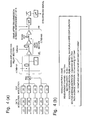
Fig. 4 and Fig. 5 are related to a simulation in
the optical transmission system shown in Fig. 1. Fig. 4(a)
is a schematic showing the optical transmission system for
use in the simulation and Fig. 4(b) is a diagram showing
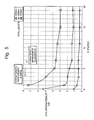
various conditions for use in the simulation. Fig. 5 is a
graph showing a result of the simulation. Hereinafter, the
embodiment is described by referring to these drawings.
As shown in Fig. 4(a), a basic block unit
comprises N Raman amplification relay sections and a single
EDFA relay section disposed in a subsequent stage of the
Raman amplification relay sections. The optical
transmission system for use in the simulation is formed by
repeating the basic block unit M times. In the optical
transmission system shown in Fig. 4(a), the simulation has
been performed under the conditions shown in Fig. 4(b).
Main abbreviations shown in Fig. 4 are then
described here: LN (LiNbO3 waveguide-type optical
modulator), PBS (polarization beam splitter), DCF
(dispersion compensation fiber), OSNR (optical signal to
noise ratio), BPF (band pass filter), LPF (low pass filter),
and SMF (single mode optical fiber).
Deterioration of an optical signal includes
deterioration caused by noise added by an optical amplifier
and deterioration caused by nonlinear optical effects that
occurs during transmission. The former can be calculated
relatively easily, while the latter need be quantified with
an actual experiment or a simulation. Therefore, the
latter deterioration has been quantified with a simulation
under the condition of a fixed total amount of noise (OSNR
fixed) that occurs in the optical amplifier. A result of
the simulation is shown in Fig. 5.
The abscissa axis in Fig. 5 represents the number
N of the Raman amplification relay sections to the single
EDFA relay section. N=0 indicates that only the EDFA relay
section exists. The ordinate axis in Fig. 5 represents an
eye-opening penalty. An aperture between a mark and a
space at an identification time is referred to as eye
opening. As the eye opening increases, an allowance for
noise grows. An existence of a waveform distortion makes
the eye opening narrow, thereby increasing received light
power for acquiring a necessary bit error rate (BER). The
eye-opening penalty is obtained by subtracting an eye
opening at the receiving end from an eye opening at the
transmission in dB. In other words, as the eye-opening
penalty increases, the waveform distortion grows.
If the number of the Raman amplification relay
sections decreases relative to the EDFA relay section, the
eye-opening penalty increases. The reason for it is as
follows. The Raman amplifier emits pumping light to the
transmission line and amplifies it. Therefore, as apparent
from Fig. 3, loss occurs simultaneously with the
amplification on the transmission line, thus relatively
increasing the minimum loss level. On the other hand, as
for the EDFA, only loss occurs on the transmission line,
thus causing the minimum loss level just before the
amplification to be low. There is no big difference
between them in noise levels. Therefore, the EDFA having
the lower minimum loss level has an OSNR more deteriorated
than that of the Raman amplifier. As noise is amplified
together with a signal light in each amplifier, the signal
light is amplified in a deteriorated OSNR condition in the
EDFA consequently. Therefore, as the ratio of the EDFA to
the Raman amplifiers increases, the OSNR deteriorates, by
which the eye-opening penalty increases consequently.
On the other hand, it will now be considered that
the minimum loss level in the EDFA relay section is
controlled to be the same as in the Raman amplification
relay section to prevent the above. To achieve it, the
output level of the EDFA need be higher than that of the
Raman amplifier. An increase of signal light power in the
optical transmission line, however, causes another problem
of easily causing nonlinear optical effects. Particularly,
in the case of a high-speed transmission of 40 Gb/s, it
causes SPM-GVD that is a synergistic action of an
accumulated dispersion and the nonlinear optical effects.
It deteriorates the transmission waveform significantly,
thus increasing the eye-opening penalty consequently.
Therefore, in both cases, the eye-opening penalty
of the EDFA relay section easily gets higher than that of
the Raman amplification relay section.
Therefore, as apparent from the graph of Fig. 5, N
is preferably 3 or greater, more preferably 4 or greater,
most preferably 5 or greater.
When N is smaller than 5, as the total length is
greater, the eye-opening penalty sharply grows. It is
because the greater total length causes the deterioration
of the OSNR to be more easily accumulated.
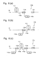
Referring to Fig. 6, there is shown a schematic of
an example of the Raman amplification relay section
according to the present invention: Fig. 6(a) shows a first
example, Fig. 6(b) shows a second example, and Fig. 6(c)
shows a third example. Hereinafter, the description will
be made by referring to these drawings. Note that, however,
like reference numerals refer to the same parts as in Fig.
1(b), thereby omitting the description.
A Raman amplification relay section 11a in Fig.
6(a) has the same configuration as for the Raman
amplification relay section 11 in Fig. 1(b), which is of a
counter-propagating pumping type emitting pumping light
116a in a reverse direction to a signal light 31. A Raman
amplification relay section 11b in Fig. 6(b) is of a co-propagating
pumping type emitting pumping light 116b in the
same direction as for the signal light 31. A Raman
amplification relay section 11c in Fig. 6(c) has both
configurations of the counter-propagating pumping type
emitting the pumping light 116a in the reverse direction to
the signal light 31 and the co-propagating pumping type
emitting the pumping light 116b in the same direction as
for the signal light 31. It is possible to use any Raman
amplification relay section among (a) to (c) in the above.
Also in the EDFA, any of the co-propagating
pumping type, the counter-propagating pumping type, and co-propagating
and counter-propagating pumping type can be
used as described above.
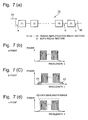
Referring to Fig. 7, there is shown an explanatory
diagram of an operation of reducing an amplified
spontaneous emission (ASE) noise outside the signal
wavelength range in the optical transmission system in Fig.
1. Hereinafter, the description will be made by referring
to Fig. 1 to Fig. 7.
If a plurality of pumping wavelengths are used for
securing gain flatness in the Raman amplification relay
sections 11 to 1N, a gain occurs outside the signal
wavelength range, too. This easily causes the ASE noise.
Accordingly, a wavelength range of an EDFA 217 is set in
such a way as to remove the ASE light by using a filter or
the like (not shown). With this, the ASE noise outside the
signal wavelength range can be inhibited.
Referring to Fig. 7(a), there is shown a basic
block unit 30 comprising the Raman amplification relay
sections 11 to 1N and the EDFA relay section 21 at a ratio
of N to 1. A signal at the a point in Fig. 7(a) has just
entered the basic block unit 30 and has not been affected
yet by the Raman amplification relay section. A spectrum
of this signal is shown in Fig. 7(b). A signal at the b
point in Fig. 7(a) has just passed the N Raman
amplification relay sections 11 to 1N. A spectrum of this
signal is shown in Fig. 7(c). As shown, ASE noises 41 and
42 occur outside the signal wavelength range. A signal at
the c point in Fig. 7(a) has just passed the EDFA relay
section 21. A spectrum of this signal is shown in Fig.
7(d). By using the EDFA 217 having a wavelength range 43
as shown in Fig. 7(d) for the EDFA relay section 21, the
ASE noises 41 and 42 shown in Fig. 7(c) can be removed.
Naturally the present invention is not limited to
the above embodiments. For example, a thulium doped fiber
amplifier (TDFA) or the like can be used instead of the
EDFA.
As set forth hereinabove, according to the optical
transmission system of the present invention, even if a
signal level significantly deviates from a setting value in
a plurality of first optical amplification relay sections
with Raman amplifiers, it is possible to return the output
signal level to the setting value in a second optical
amplification relay section with an optical fiber amplifier
(for example, an EDFA) disposed in the subsequent stage.
Therefore, according to the present invention,
even if a signal level changes due to a failure or a
disturbance in the first optical amplification relay
sections, the signal level can be returned to the initial
setting value. It is because an optical fiber amplifier
(for example, an EDFA) disposed in the subsequent stage is
operating with a control of output uniformity.
The Raman amplifier has a feature of decreasing
peak power of a signal light in an optical fiber at a low
level, thereby preventing deterioration of a signal-to-noise
ratio (SN ratio) and therefore preventing the
transmission deterioration caused by nonlinear optical
effects. It, however, has a weakness of being susceptible
to deterioration with time. On the other hand, an optical
fiber amplifier has a feature of achieving a stable quality
against deterioration with time. It, however, has a
weakness of having trouble in keeping the peak power low,
thereby easily having transmission deterioration caused by
nonlinear optical effects. Therefore, with a plurality of
Raman amplifiers and a single optical fiber amplifier, they
make up for each other's weaknesses so as to utilize their
own features. The optical transmission system according to
the present invention is capable of preventing both of the
quality deterioration and deterioration with time in
transmissions.
To enhance these effects, it is more preferable
that the ratio of the first optical amplification relay
sections to the second optical amplification relay section
is 5 or greater to 1. In addition, it is more preferable
that the Raman amplifier has a uniform gain and the optical
fiber amplifier has a uniform output signal level.
Furthermore, according to the present invention,
the amplification wavelength range of the second optical
amplification relay section with the optical fiber
amplifier is set to a signal wavelength range, thereby
effectively removing an ASE noise accumulated outside the
signal wavelength range by means of the first optical
amplification relay sections with the Raman amplifiers.
While the present invention has been described in
connection with certain preferred embodiments, it is to be
understood that the subject matter encompassed by way of
this invention is not limited to those specific embodiments.
On the contrary, it is intended for the subject matter of
the invention to include all alternative, modification, and
equivalents as can be included within the spirit and scope
of the following claims.