EP1416595B1 - Double clad fiber amplifier - Google Patents
Double clad fiber amplifier Download PDFInfo
- Publication number
- EP1416595B1 EP1416595B1 EP02360303A EP02360303A EP1416595B1 EP 1416595 B1 EP1416595 B1 EP 1416595B1 EP 02360303 A EP02360303 A EP 02360303A EP 02360303 A EP02360303 A EP 02360303A EP 1416595 B1 EP1416595 B1 EP 1416595B1
- Authority
- EP
- European Patent Office
- Prior art keywords
- cladding
- refractive index
- fiber amplifier
- core
- optical fiber
- Prior art date
- Legal status (The legal status is an assumption and is not a legal conclusion. Google has not performed a legal analysis and makes no representation as to the accuracy of the status listed.)
- Expired - Lifetime
Links
- 239000000835 fiber Substances 0.000 title claims description 4
- 238000005253 cladding Methods 0.000 claims abstract description 44
- 239000013307 optical fiber Substances 0.000 claims abstract description 15
- 150000002910 rare earth metals Chemical class 0.000 claims abstract description 9
- 230000003247 decreasing effect Effects 0.000 claims abstract description 7
- 229910052761 rare earth metal Inorganic materials 0.000 claims abstract description 6
- 239000000463 material Substances 0.000 claims abstract description 4
- 230000003287 optical effect Effects 0.000 claims description 2
- 230000003993 interaction Effects 0.000 description 10
- 238000005086 pumping Methods 0.000 description 5
- 238000004519 manufacturing process Methods 0.000 description 4
- 238000006243 chemical reaction Methods 0.000 description 3
- 238000010168 coupling process Methods 0.000 description 3
- 238000005859 coupling reaction Methods 0.000 description 3
- 230000008878 coupling Effects 0.000 description 2
- 238000009826 distribution Methods 0.000 description 2
- 229910052691 Erbium Inorganic materials 0.000 description 1
- 229910052769 Ytterbium Inorganic materials 0.000 description 1
- 230000002238 attenuated effect Effects 0.000 description 1
- 230000002860 competitive effect Effects 0.000 description 1
- 230000001143 conditioned effect Effects 0.000 description 1
- 230000001419 dependent effect Effects 0.000 description 1
- 230000001627 detrimental effect Effects 0.000 description 1
- 238000011161 development Methods 0.000 description 1
- 230000018109 developmental process Effects 0.000 description 1
- 239000002019 doping agent Substances 0.000 description 1
- UYAHIZSMUZPPFV-UHFFFAOYSA-N erbium Chemical compound [Er] UYAHIZSMUZPPFV-UHFFFAOYSA-N 0.000 description 1
- 230000001902 propagating effect Effects 0.000 description 1
- 230000008054 signal transmission Effects 0.000 description 1
- 230000002269 spontaneous effect Effects 0.000 description 1
- NAWDYIZEMPQZHO-UHFFFAOYSA-N ytterbium Chemical compound [Yb] NAWDYIZEMPQZHO-UHFFFAOYSA-N 0.000 description 1
Images

Classifications
-
- H—ELECTRICITY
- H01—ELECTRIC ELEMENTS
- H01S—DEVICES USING THE PROCESS OF LIGHT AMPLIFICATION BY STIMULATED EMISSION OF RADIATION [LASER] TO AMPLIFY OR GENERATE LIGHT; DEVICES USING STIMULATED EMISSION OF ELECTROMAGNETIC RADIATION IN WAVE RANGES OTHER THAN OPTICAL
- H01S3/00—Lasers, i.e. devices using stimulated emission of electromagnetic radiation in the infrared, visible or ultraviolet wave range
- H01S3/05—Construction or shape of optical resonators; Accommodation of active medium therein; Shape of active medium
- H01S3/06—Construction or shape of active medium
- H01S3/063—Waveguide lasers, i.e. whereby the dimensions of the waveguide are of the order of the light wavelength
- H01S3/067—Fibre lasers
- H01S3/06708—Constructional details of the fibre, e.g. compositions, cross-section, shape or tapering
-
- H—ELECTRICITY
- H01—ELECTRIC ELEMENTS
- H01S—DEVICES USING THE PROCESS OF LIGHT AMPLIFICATION BY STIMULATED EMISSION OF RADIATION [LASER] TO AMPLIFY OR GENERATE LIGHT; DEVICES USING STIMULATED EMISSION OF ELECTROMAGNETIC RADIATION IN WAVE RANGES OTHER THAN OPTICAL
- H01S3/00—Lasers, i.e. devices using stimulated emission of electromagnetic radiation in the infrared, visible or ultraviolet wave range
- H01S3/05—Construction or shape of optical resonators; Accommodation of active medium therein; Shape of active medium
- H01S3/06—Construction or shape of active medium
- H01S3/063—Waveguide lasers, i.e. whereby the dimensions of the waveguide are of the order of the light wavelength
- H01S3/067—Fibre lasers
- H01S3/06708—Constructional details of the fibre, e.g. compositions, cross-section, shape or tapering
- H01S3/06729—Peculiar transverse fibre profile
-
- H—ELECTRICITY
- H01—ELECTRIC ELEMENTS
- H01S—DEVICES USING THE PROCESS OF LIGHT AMPLIFICATION BY STIMULATED EMISSION OF RADIATION [LASER] TO AMPLIFY OR GENERATE LIGHT; DEVICES USING STIMULATED EMISSION OF ELECTROMAGNETIC RADIATION IN WAVE RANGES OTHER THAN OPTICAL
- H01S3/00—Lasers, i.e. devices using stimulated emission of electromagnetic radiation in the infrared, visible or ultraviolet wave range
- H01S3/05—Construction or shape of optical resonators; Accommodation of active medium therein; Shape of active medium
- H01S3/06—Construction or shape of active medium
- H01S3/063—Waveguide lasers, i.e. whereby the dimensions of the waveguide are of the order of the light wavelength
- H01S3/067—Fibre lasers
- H01S3/06754—Fibre amplifiers
-
- H—ELECTRICITY
- H01—ELECTRIC ELEMENTS
- H01S—DEVICES USING THE PROCESS OF LIGHT AMPLIFICATION BY STIMULATED EMISSION OF RADIATION [LASER] TO AMPLIFY OR GENERATE LIGHT; DEVICES USING STIMULATED EMISSION OF ELECTROMAGNETIC RADIATION IN WAVE RANGES OTHER THAN OPTICAL
- H01S3/00—Lasers, i.e. devices using stimulated emission of electromagnetic radiation in the infrared, visible or ultraviolet wave range
- H01S3/09—Processes or apparatus for excitation, e.g. pumping
- H01S3/091—Processes or apparatus for excitation, e.g. pumping using optical pumping
- H01S3/094—Processes or apparatus for excitation, e.g. pumping using optical pumping by coherent light
- H01S3/094003—Processes or apparatus for excitation, e.g. pumping using optical pumping by coherent light the pumped medium being a fibre
- H01S3/094007—Cladding pumping, i.e. pump light propagating in a clad surrounding the active core
Definitions
- the invention relates to an optical fiber amplifier comprising a mono-mode core, a first cladding around said core and at least a further cladding around said first cladding while said first cladding including a ring doped with rare earth material surrounding said mono-mode core.
- US6,288,835 is described a waveguide optical amplifier with improved interaction properties between the light guided along a waveguide and the rare earth dopants within an active medium by confining said active medium being the amplifying region to a ring inside a cladding around the core of said waveguide.
- the regions of the ring are preferably chosen where the intensity of the signal beam is substantially smaller than its peak intensity, in a cross-section of the waveguiding device perpendicular to the direction of propagation of the signal beam.
- the pumping light is supplied by a high-power laser coupled preferably at the cladding around the core of said waveguide.
- the luminous energy supplied to the cladding in this way will be absorbed by the core as soon as the amplified light rays propagating in the cladding cross the interface between the core and the cladding.
- the efficiency of energy pumping is mostly conditioned by the efficiency of the coupling between the core and the cladding.
- the object of the present invention is to design an optical fiber amplifier with an optimized power conversion efficiency between the pumping light and the signal light without implying a to costly manufacturing method.
- an optical fiber amplifier comprising a mono-mode core, a first cladding around said core and at least a further cladding around said first cladding while said first cladding includes a ring doped with rare earth material surrounding said mono-mode core.
- the first cladding is designed with a radial refractive index following an almost continuous decreasing function for increasing radius.
- the use of a continuously decreasing refractive index for the cladding at the outer border of the ring shaped active medium optimize the efficiency of the coupling between the core and the cladding. It is then, no more necessary to chose a complicated and expensive way to manufacture polygonal shape for the outer border of said first cladding.
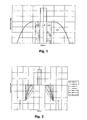
- FIG 1 On figure 1 is shown a cross section of the central part of an optical fiber amplifier according to the invention.
- a mono-mode core with the highest refractive index n1 of the fiber.
- Such mono-mode core is surrounded by a first cladding with a refractive index n2 substantially lower than n1.
- At least a further cladding with refractive index n3 is designed around said first cladding.
- the active region with refractive index n4 used for pumping is defined in a ring geometry in cross section around said mono-mode core. It is obtained by doping said region with rare earth atoms like Erbium (Er) or Ytterbium (Yb).
- the novelty of the present invention is to chose to fit the radial refractive index of the first cladding as a function of the radius to a continuous decreasing function as shown on figure 1 . This will optimize the overlap between the doping region and the modes conveying the pump signal by putting more power into modes of higher propagation constant as compared with modes of lower propagation constant values which are expected to be more attenuated along the fiber by mode mixing phenomenon.
- a maximum of the pumping light coupled into the active ring-shaped region with refractive index n4 will be used to amplifier signal lights transmitted through the mono-mode core with refractive index n1.
- n2 may be preferable to chose said continuous decreasing function of the radial refractive index n2 with a negative slope. It is also of advantage to set the radial refractive index to decrease only almost at the outer border of the ring-shaped active region (n4). In that case, it is conceivable to fix the refractive index n4 of the active region substantially to some constant value possibly matching the maximum value n2_max of the radial refractive index n2 of the first cladding.
- the active region doped with rare earth atoms is almost directly adjacent to said mono-mode core. It is also possible to envisage that the active region in cross section ring shaped is partly included into said mono-mode core.
- the size of said active region is to be chosen according to the destined application. Preferably, the lower radius r1 will be chosen around 3 to 3.5 ⁇ m and the upper radius r2 around 6 ⁇ m.
- the first cladding surrounding the mono-mode core is defined with a radial refractive index n2 according to the invention, it is no more necessary to break the circular symmetry of its cross sectional outer surface as in prior art. Therefore, it is possible and preferable for a manufacturing point of view to design said first cladding substantially with a concentric outer shape.
- n ⁇ 2 r n ⁇ 2 _max * 1 - 2 ⁇ ⁇ ⁇ r - r ⁇ 1 / r ⁇ 2 - r ⁇ 1 ⁇ ⁇ ⁇
- ⁇ (n2_max ⁇ 2 - n3 ⁇ 2) / (2*n2_max ⁇ 2).
- the radius r is defined between r1 and r2, r1 being the outer radius of the mono-mode core or the active region, and r2 the outer radius of the first cladding.
- the parameter ⁇ can take any value while the case ⁇ ⁇ ⁇ is identical to the step like function (see figure 2 ) already discussed in preceding discussed prior art.
Landscapes
- Physics & Mathematics (AREA)
- Electromagnetism (AREA)
- Engineering & Computer Science (AREA)
- Plasma & Fusion (AREA)
- Optics & Photonics (AREA)
- Lasers (AREA)
- Vehicle Body Suspensions (AREA)
- Surgical Instruments (AREA)
Abstract
Description
- The invention relates to an optical fiber amplifier comprising a mono-mode core, a first cladding around said core and at least a further cladding around said first cladding while said first cladding including a ring doped with rare earth material surrounding said mono-mode core.
- The tightly confined modal fields of single- or few-moded waveguiding lasers and amplifiers lead to a very strong interaction between any waveguided light and the active medium in the waveguiding core. Therefore, a comparatively small amount of gain medium is sufficient for providing the gain in these devices. Specifically, the gain for a given stored energy, as well as for a given absorbed pump power, is high.
- However, this efficient interaction between mode and gain medium can be detrimental. Indeed, in a laser or amplifier, the achievable single-pass gain is limited to some maximum value (e.g. 50dB). The reason is that at the maximum, a significant fraction of the pump power is converted to amplified spontaneous emission (ASE). A 10dB higher gain results in approximately 10dB more ASE. At these gains, the extra pump power required to increase the gain further will be prohibitively high. Since the ASE limits the gain of the device, it also limits the energy stored in the gain media. This in turn obviously limits the amount of energy that a pulse can extract from the device. Consequently, the pulse energy that can be obtained from waveguide lasers and amplifiers is limited.
- Furthermore, in optically pumped lasers and amplifiers, it is essential to optimize the interaction between the gain medium and the amplified field or generated signal beam as well as the interaction between the pump beam and the gain medium. However, in typically cladding-pumped lasers and amplifiers, the interaction with the pump beam is significantly smaller than the interaction with the signal beam. Then, for a device that efficiently absorbs the pump, the interaction with the signal beam will be much stronger than what is required. Unfortunately, this excess interaction is often accompanied by excess losses for the signal beam.
- In
US6,288,835 is described a waveguide optical amplifier with improved interaction properties between the light guided along a waveguide and the rare earth dopants within an active medium by confining said active medium being the amplifying region to a ring inside a cladding around the core of said waveguide. The regions of the ring are preferably chosen where the intensity of the signal beam is substantially smaller than its peak intensity, in a cross-section of the waveguiding device perpendicular to the direction of propagation of the signal beam. Thus, the interaction between a signal light beam and an active medium are considerably reduced without necessarily changing the properties of the gain medium or reducing the confinement of the signal light. - The pumping light is supplied by a high-power laser coupled preferably at the cladding around the core of said waveguide. The luminous energy supplied to the cladding in this way will be absorbed by the core as soon as the amplified light rays propagating in the cladding cross the interface between the core and the cladding. Obviously, the efficiency of energy pumping is mostly conditioned by the efficiency of the coupling between the core and the cladding. But a problem arises with cylindrical core/cladding interfaces, namely that some light rays conveyed by the cladding will follow a helical trajectory around the core without ever impinging on the interface. The energy conveyed by these rays is therefore injected into the cladding in vain, because it is never used to amplify the signal transported by the core.
- Several solutions have been proposed to solve this problem, in particular in
US5,949,941 andWO02/03510 - The object of the present invention is to design an optical fiber amplifier with an optimized power conversion efficiency between the pumping light and the signal light without implying a to costly manufacturing method.
- This object is achieved in accordance with the invention as defined in
claim 2 for an optical fiber amplifier comprising a mono-mode core, a first cladding around said core and at least a further cladding around said first cladding while said first cladding includes a ring doped with rare earth material surrounding said mono-mode core. Advantageously, the first cladding is designed with a radial refractive index following an almost continuous decreasing function for increasing radius. The use of a continuously decreasing refractive index for the cladding at the outer border of the ring shaped active medium optimize the efficiency of the coupling between the core and the cladding. It is then, no more necessary to chose a complicated and expensive way to manufacture polygonal shape for the outer border of said first cladding. - Advantageous developments of the invention are described in the dependent claims, the following description and the drawings.
- An exemplary embodiment of the invention will now be explained further with the reference to the attached drawings in which:
- Fig. 1
- illustrates an example of the distribution of the refractive index along a cross section of the core and the first cladding of an optical fiber amplifier according to the invention;
- Fig. 2
- illustrates several possible distributions of the refractive index along a cross section particularly of the first cladding of an optical fiber amplifier according to the invention;
- Fig. 3
- illustrates different configurations of the overlap between modes in the ring-like doped region according to the invention;
- Fig. 4
- illustrates the overlap property as a direct function of the slope of the radial refractive index of the first cladding according to the invention.
- On
figure 1 is shown a cross section of the central part of an optical fiber amplifier according to the invention. At the center of such waveguide is designed a mono-mode core with the highest refractive index n1 of the fiber. Such mono-mode core is surrounded by a first cladding with a refractive index n2 substantially lower than n1. At least a further cladding with refractive index n3 is designed around said first cladding. The active region with refractive index n4 used for pumping is defined in a ring geometry in cross section around said mono-mode core. It is obtained by doping said region with rare earth atoms like Erbium (Er) or Ytterbium (Yb). - The novelty of the present invention is to chose to fit the radial refractive index of the first cladding as a function of the radius to a continuous decreasing function as shown on
figure 1 . This will optimize the overlap between the doping region and the modes conveying the pump signal by putting more power into modes of higher propagation constant as compared with modes of lower propagation constant values which are expected to be more attenuated along the fiber by mode mixing phenomenon. - Thus, a maximum of the pumping light coupled into the active ring-shaped region with refractive index n4 will be used to amplifier signal lights transmitted through the mono-mode core with refractive index n1.
- It may be preferable to chose said continuous decreasing function of the radial refractive index n2 with a negative slope. It is also of advantage to set the radial refractive index to decrease only almost at the outer border of the ring-shaped active region (n4). In that case, it is conceivable to fix the refractive index n4 of the active region substantially to some constant value possibly matching the maximum value n2_max of the radial refractive index n2 of the first cladding.
- In the present case as shown on
figure 1 , the active region doped with rare earth atoms is almost directly adjacent to said mono-mode core. It is also possible to envisage that the active region in cross section ring shaped is partly included into said mono-mode core. The size of said active region is to be chosen according to the destined application. Preferably, the lower radius r1 will be chosen around 3 to 3.5µm and the upper radius r2 around 6µm. - When the first cladding surrounding the mono-mode core is defined with a radial refractive index n2 according to the invention, it is no more necessary to break the circular symmetry of its cross sectional outer surface as in prior art. Therefore, it is possible and preferable for a manufacturing point of view to design said first cladding substantially with a concentric outer shape.
- It may be of advantage to choose for the radial refractive index of the first cladding a typical function used in the design of classical optical fibers for transmission of signals and defined by the following function:

figure 2 ) already discussed in preceding discussed prior art. - To fulfill the requirements of the present invention, it is necessary when using above function for n2(r) to chose the parameter α preferably bigger than 1 e.g. α = 2 or 3. On
figure 3 is shown different results of the overlap between modes and the active ring shaped region (doped region) as a function of the mode group index. It appears clearly that there is no need of implementing an outer shape with circularly broken symmetry for mode-mixing enhancement. Onfigure 4 the overlap for the first mode is shown as function of α. The dashed line represents the asymptotic value when alpha tends to infinity. A clear higher pump power conversion efficiency when using present invention can be achieved asfigure 4 shows a better overlap with the active region doped with rare earth atoms.
Claims (7)
- Optical fiber amplifier comprising a mono-mode core with a refractive index n1, a first cladding around said core with a refractive index n2 and at least a further cladding around said first cladding with a refractive index n3 while said first cladding including in cross section a ring-shaped region with a refractive index n4 doped with rare earth material surrounding said mono-mode core, characterized in, that said first cladding shows at least partly a radial refractive index n2 as a function of the radius from the center of the core being almost continuously decreasing.
- Optical fiber amplifier according to claim 1, characterized in, that said decreasing function is defined with a negative slope
- Optical fiber amplifier according to claim 1, characterized in, that said ring shows an almost constant radial refractive index n4 while the radial refractive index n2 starts to decrease almost at the outer border of said ring.
- Optical fiber amplifier according to claim 1, characterized in, that said ring is almost directly adjacent to said mono-mode core.
- Optical fiber amplifier according to claim 1, characterized in, that said ring is partly included into said mono-mode core.
- Optical fiber amplifier according to claim 1, characterized in, that said ring is defined with a lower radius comprised around 3µm or 3.5µm and an upper radius comprised around 6µm.
- Optical fiber amplifier according to claim 1, characterized in, that said first cladding shows an outer shape substantially concentric along the optical axis of said fiber.
Priority Applications (5)
| Application Number | Priority Date | Filing Date | Title |
|---|---|---|---|
| AT02360303T ATE396527T1 (en) | 2002-10-30 | 2002-10-30 | DOUBLE COVERED FIBER REINFORCEMENT |
| EP02360303A EP1416595B1 (en) | 2002-10-30 | 2002-10-30 | Double clad fiber amplifier |
| DE60226741T DE60226741D1 (en) | 2002-10-30 | 2002-10-30 | Double jacketed fiber amplifier |
| ES02360303T ES2305190T3 (en) | 2002-10-30 | 2002-10-30 | DOUBLE COATING FIBER AMPLIFIER. |
| US10/671,482 US7034995B2 (en) | 2002-10-30 | 2003-09-29 | Enhanced pump absorbing double-clad fiber |
Applications Claiming Priority (1)
| Application Number | Priority Date | Filing Date | Title |
|---|---|---|---|
| EP02360303A EP1416595B1 (en) | 2002-10-30 | 2002-10-30 | Double clad fiber amplifier |
Publications (2)
| Publication Number | Publication Date |
|---|---|
| EP1416595A1 EP1416595A1 (en) | 2004-05-06 |
| EP1416595B1 true EP1416595B1 (en) | 2008-05-21 |
Family
ID=32088093
Family Applications (1)
| Application Number | Title | Priority Date | Filing Date |
|---|---|---|---|
| EP02360303A Expired - Lifetime EP1416595B1 (en) | 2002-10-30 | 2002-10-30 | Double clad fiber amplifier |
Country Status (5)
| Country | Link |
|---|---|
| US (1) | US7034995B2 (en) |
| EP (1) | EP1416595B1 (en) |
| AT (1) | ATE396527T1 (en) |
| DE (1) | DE60226741D1 (en) |
| ES (1) | ES2305190T3 (en) |
Families Citing this family (2)
| Publication number | Priority date | Publication date | Assignee | Title |
|---|---|---|---|---|
| FR2852154B1 (en) * | 2003-03-04 | 2005-05-20 | Cit Alcatel | AMPLIFIER OPTICAL FIBER WITH DOPE RING AND AMPLIFIER CONTAINING SUCH A FIBER |
| US7455460B2 (en) * | 2007-03-08 | 2008-11-25 | Panduit Corp. | Fiber optic connector with double-clad stub fiber |
Family Cites Families (7)
| Publication number | Priority date | Publication date | Assignee | Title |
|---|---|---|---|---|
| GB9625231D0 (en) | 1996-12-04 | 1997-01-22 | Univ Southampton | Optical amplifiers & lasers |
| JPH11121839A (en) * | 1997-10-17 | 1999-04-30 | Fujitsu Ltd | Optical amplification fiber and optical fiber amplifier |
| US5949941A (en) | 1997-11-21 | 1999-09-07 | Lucent Technologies Inc. | Cladding-pumped fiber structures |
| US6317549B1 (en) * | 1999-05-24 | 2001-11-13 | Lucent Technologies Inc. | Optical fiber having negative dispersion and low slope in the Erbium amplifier region |
| JP2001235649A (en) * | 2000-02-23 | 2001-08-31 | Sumitomo Electric Ind Ltd | Optical fiber |
| FR2811437A1 (en) | 2000-07-06 | 2002-01-11 | Cit Alcatel | SHEATH PUMPED OPTICAL FIBER AND METHOD FOR MANUFACTURING SUCH FIBER |
| US6819846B2 (en) * | 2001-08-02 | 2004-11-16 | Corning Incorporated | High absorption erbium doped amplifying optical fiber |
-
2002
- 2002-10-30 EP EP02360303A patent/EP1416595B1/en not_active Expired - Lifetime
- 2002-10-30 ES ES02360303T patent/ES2305190T3/en not_active Expired - Lifetime
- 2002-10-30 AT AT02360303T patent/ATE396527T1/en not_active IP Right Cessation
- 2002-10-30 DE DE60226741T patent/DE60226741D1/en not_active Expired - Lifetime
-
2003
- 2003-09-29 US US10/671,482 patent/US7034995B2/en not_active Expired - Lifetime
Also Published As
| Publication number | Publication date |
|---|---|
| US20040085623A1 (en) | 2004-05-06 |
| ES2305190T3 (en) | 2008-11-01 |
| ATE396527T1 (en) | 2008-06-15 |
| DE60226741D1 (en) | 2008-07-03 |
| US7034995B2 (en) | 2006-04-25 |
| EP1416595A1 (en) | 2004-05-06 |
Similar Documents
| Publication | Publication Date | Title |
|---|---|---|
| EP1935068B1 (en) | Optical fibre laser | |
| US8498044B2 (en) | Amplification optical fiber, and optical fiber amplifier and resonator using the same | |
| US6118575A (en) | Optical fiber gain medium with evanescent filtering | |
| JP5484073B2 (en) | Selective excitation of gain-doped regions in optical fibers. | |
| KR101750861B1 (en) | Multimode fiber | |
| CN102668273B (en) | Single mode high power fiber laser system | |
| US8456737B2 (en) | Amplification optical fiber and optical fiber amplifier and resonator using the same | |
| US7340140B1 (en) | Er/Yb double clad photonic crystal fiber | |
| EP2724429B1 (en) | High power single mode ytterbium fiber laser system with single mode neodymium fiber source | |
| JP6294486B2 (en) | Ultra high power single mode fiber laser system | |
| US6240108B1 (en) | Cladding pumped fiber laser with reduced overlap between a laser mode and an ion-doped region | |
| JP4959314B2 (en) | Rare earth doped large mode area multimode optical fiber and device using the same | |
| JP2025179242A (en) | Active waveguides for high-power, high-efficiency ECO lasers. | |
| US7034995B2 (en) | Enhanced pump absorbing double-clad fiber | |
| JP4799810B2 (en) | Double clad fiber and optical amplification method using the same | |
| WO2020203930A1 (en) | Active element added-optical fiber, resonator, and fiber laser device | |
| WO2001011736A1 (en) | Waveguide laser | |
| WO1997033460A2 (en) | Multicore fiber optic amplifier |
Legal Events
| Date | Code | Title | Description |
|---|---|---|---|
| PUAI | Public reference made under article 153(3) epc to a published international application that has entered the european phase |
Free format text: ORIGINAL CODE: 0009012 |
|
| 17P | Request for examination filed |
Effective date: 20030602 |
|
| AK | Designated contracting states |
Kind code of ref document: A1 Designated state(s): AT BE BG CH CY CZ DE DK EE ES FI FR GB GR IE IT LI LU MC NL PT SE SK TR |
|
| AX | Request for extension of the european patent |
Extension state: AL LT LV MK RO SI |
|
| AKX | Designation fees paid |
Designated state(s): AT BE BG CH CY CZ DE DK EE ES FI FR GB GR IE IT LI LU MC NL PT SE SK TR |
|
| RAP1 | Party data changed (applicant data changed or rights of an application transferred) |
Owner name: ALCATEL LUCENT |
|
| GRAP | Despatch of communication of intention to grant a patent |
Free format text: ORIGINAL CODE: EPIDOSNIGR1 |
|
| GRAS | Grant fee paid |
Free format text: ORIGINAL CODE: EPIDOSNIGR3 |
|
| GRAA | (expected) grant |
Free format text: ORIGINAL CODE: 0009210 |
|
| AK | Designated contracting states |
Kind code of ref document: B1 Designated state(s): AT BE BG CH CY CZ DE DK EE ES FI FR GB GR IE IT LI LU MC NL PT SE SK TR |
|
| REG | Reference to a national code |
Ref country code: GB Ref legal event code: FG4D |
|
| RIN1 | Information on inventor provided before grant (corrected) |
Inventor name: BAYART, DOMINIQUE Inventor name: MOREAU, CHRISTINE Inventor name: SIMONNEAU, CHRISTIAN Inventor name: BONGRAND, ISABELLE Inventor name: GASCA, LAURENT Inventor name: PROVOST, LIONEL Inventor name: BOUSSELET, PHILIPPE |
|
| REG | Reference to a national code |
Ref country code: CH Ref legal event code: EP |
|
| REF | Corresponds to: |
Ref document number: 60226741 Country of ref document: DE Date of ref document: 20080703 Kind code of ref document: P |
|
| REG | Reference to a national code |
Ref country code: IE Ref legal event code: FG4D |
|
| PG25 | Lapsed in a contracting state [announced via postgrant information from national office to epo] |
Ref country code: FI Free format text: LAPSE BECAUSE OF FAILURE TO SUBMIT A TRANSLATION OF THE DESCRIPTION OR TO PAY THE FEE WITHIN THE PRESCRIBED TIME-LIMIT Effective date: 20080521 |
|
| REG | Reference to a national code |
Ref country code: ES Ref legal event code: FG2A Ref document number: 2305190 Country of ref document: ES Kind code of ref document: T3 |
|
| NLV1 | Nl: lapsed or annulled due to failure to fulfill the requirements of art. 29p and 29m of the patents act | ||
| PG25 | Lapsed in a contracting state [announced via postgrant information from national office to epo] |
Ref country code: AT Free format text: LAPSE BECAUSE OF FAILURE TO SUBMIT A TRANSLATION OF THE DESCRIPTION OR TO PAY THE FEE WITHIN THE PRESCRIBED TIME-LIMIT Effective date: 20080521 Ref country code: NL Free format text: LAPSE BECAUSE OF FAILURE TO SUBMIT A TRANSLATION OF THE DESCRIPTION OR TO PAY THE FEE WITHIN THE PRESCRIBED TIME-LIMIT Effective date: 20080521 |
|
| PG25 | Lapsed in a contracting state [announced via postgrant information from national office to epo] |
Ref country code: SE Free format text: LAPSE BECAUSE OF FAILURE TO SUBMIT A TRANSLATION OF THE DESCRIPTION OR TO PAY THE FEE WITHIN THE PRESCRIBED TIME-LIMIT Effective date: 20080821 Ref country code: CZ Free format text: LAPSE BECAUSE OF FAILURE TO SUBMIT A TRANSLATION OF THE DESCRIPTION OR TO PAY THE FEE WITHIN THE PRESCRIBED TIME-LIMIT Effective date: 20080521 Ref country code: DK Free format text: LAPSE BECAUSE OF FAILURE TO SUBMIT A TRANSLATION OF THE DESCRIPTION OR TO PAY THE FEE WITHIN THE PRESCRIBED TIME-LIMIT Effective date: 20080521 Ref country code: PT Free format text: LAPSE BECAUSE OF FAILURE TO SUBMIT A TRANSLATION OF THE DESCRIPTION OR TO PAY THE FEE WITHIN THE PRESCRIBED TIME-LIMIT Effective date: 20081021 |
|
| PG25 | Lapsed in a contracting state [announced via postgrant information from national office to epo] |
Ref country code: SK Free format text: LAPSE BECAUSE OF FAILURE TO SUBMIT A TRANSLATION OF THE DESCRIPTION OR TO PAY THE FEE WITHIN THE PRESCRIBED TIME-LIMIT Effective date: 20080521 Ref country code: BE Free format text: LAPSE BECAUSE OF FAILURE TO SUBMIT A TRANSLATION OF THE DESCRIPTION OR TO PAY THE FEE WITHIN THE PRESCRIBED TIME-LIMIT Effective date: 20080521 |
|
| PLBE | No opposition filed within time limit |
Free format text: ORIGINAL CODE: 0009261 |
|
| STAA | Information on the status of an ep patent application or granted ep patent |
Free format text: STATUS: NO OPPOSITION FILED WITHIN TIME LIMIT |
|
| 26N | No opposition filed |
Effective date: 20090224 |
|
| PG25 | Lapsed in a contracting state [announced via postgrant information from national office to epo] |
Ref country code: BG Free format text: LAPSE BECAUSE OF FAILURE TO SUBMIT A TRANSLATION OF THE DESCRIPTION OR TO PAY THE FEE WITHIN THE PRESCRIBED TIME-LIMIT Effective date: 20080821 Ref country code: EE Free format text: LAPSE BECAUSE OF FAILURE TO SUBMIT A TRANSLATION OF THE DESCRIPTION OR TO PAY THE FEE WITHIN THE PRESCRIBED TIME-LIMIT Effective date: 20080521 |
|
| PG25 | Lapsed in a contracting state [announced via postgrant information from national office to epo] |
Ref country code: MC Free format text: LAPSE BECAUSE OF NON-PAYMENT OF DUE FEES Effective date: 20081031 |
|
| REG | Reference to a national code |
Ref country code: CH Ref legal event code: PL |
|
| REG | Reference to a national code |
Ref country code: IE Ref legal event code: MM4A |
|
| PG25 | Lapsed in a contracting state [announced via postgrant information from national office to epo] |
Ref country code: CH Free format text: LAPSE BECAUSE OF NON-PAYMENT OF DUE FEES Effective date: 20081031 Ref country code: LI Free format text: LAPSE BECAUSE OF NON-PAYMENT OF DUE FEES Effective date: 20081031 Ref country code: IE Free format text: LAPSE BECAUSE OF NON-PAYMENT OF DUE FEES Effective date: 20081030 |
|
| PG25 | Lapsed in a contracting state [announced via postgrant information from national office to epo] |
Ref country code: LU Free format text: LAPSE BECAUSE OF NON-PAYMENT OF DUE FEES Effective date: 20081030 Ref country code: CY Free format text: LAPSE BECAUSE OF FAILURE TO SUBMIT A TRANSLATION OF THE DESCRIPTION OR TO PAY THE FEE WITHIN THE PRESCRIBED TIME-LIMIT Effective date: 20080521 |
|
| PG25 | Lapsed in a contracting state [announced via postgrant information from national office to epo] |
Ref country code: TR Free format text: LAPSE BECAUSE OF FAILURE TO SUBMIT A TRANSLATION OF THE DESCRIPTION OR TO PAY THE FEE WITHIN THE PRESCRIBED TIME-LIMIT Effective date: 20080521 |
|
| PG25 | Lapsed in a contracting state [announced via postgrant information from national office to epo] |
Ref country code: GR Free format text: LAPSE BECAUSE OF FAILURE TO SUBMIT A TRANSLATION OF THE DESCRIPTION OR TO PAY THE FEE WITHIN THE PRESCRIBED TIME-LIMIT Effective date: 20080822 |
|
| PGFP | Annual fee paid to national office [announced via postgrant information from national office to epo] |
Ref country code: IT Payment date: 20101025 Year of fee payment: 9 |
|
| PGFP | Annual fee paid to national office [announced via postgrant information from national office to epo] |
Ref country code: ES Payment date: 20101025 Year of fee payment: 9 |
|
| PG25 | Lapsed in a contracting state [announced via postgrant information from national office to epo] |
Ref country code: IT Free format text: LAPSE BECAUSE OF NON-PAYMENT OF DUE FEES Effective date: 20111030 |
|
| REG | Reference to a national code |
Ref country code: ES Ref legal event code: FD2A Effective date: 20130604 |
|
| PG25 | Lapsed in a contracting state [announced via postgrant information from national office to epo] |
Ref country code: ES Free format text: LAPSE BECAUSE OF NON-PAYMENT OF DUE FEES Effective date: 20111031 |
|
| REG | Reference to a national code |
Ref country code: FR Ref legal event code: GC Effective date: 20131018 |
|
| REG | Reference to a national code |
Ref country code: FR Ref legal event code: RG Effective date: 20141016 |
|
| REG | Reference to a national code |
Ref country code: FR Ref legal event code: CA Effective date: 20150521 |
|
| REG | Reference to a national code |
Ref country code: FR Ref legal event code: CA Effective date: 20150521 |
|
| REG | Reference to a national code |
Ref country code: FR Ref legal event code: PLFP Year of fee payment: 14 |
|
| REG | Reference to a national code |
Ref country code: FR Ref legal event code: PLFP Year of fee payment: 15 |
|
| REG | Reference to a national code |
Ref country code: FR Ref legal event code: PLFP Year of fee payment: 16 |
|
| PGFP | Annual fee paid to national office [announced via postgrant information from national office to epo] |
Ref country code: DE Payment date: 20180425 Year of fee payment: 16 |
|
| PGFP | Annual fee paid to national office [announced via postgrant information from national office to epo] |
Ref country code: FR Payment date: 20180427 Year of fee payment: 16 |
|
| PGFP | Annual fee paid to national office [announced via postgrant information from national office to epo] |
Ref country code: GB Payment date: 20180427 Year of fee payment: 16 |
|
| REG | Reference to a national code |
Ref country code: DE Ref legal event code: R119 Ref document number: 60226741 Country of ref document: DE |
|
| GBPC | Gb: european patent ceased through non-payment of renewal fee |
Effective date: 20181030 |
|
| PG25 | Lapsed in a contracting state [announced via postgrant information from national office to epo] |
Ref country code: DE Free format text: LAPSE BECAUSE OF NON-PAYMENT OF DUE FEES Effective date: 20190501 |
|
| PG25 | Lapsed in a contracting state [announced via postgrant information from national office to epo] |
Ref country code: FR Free format text: LAPSE BECAUSE OF NON-PAYMENT OF DUE FEES Effective date: 20181031 |
|
| PG25 | Lapsed in a contracting state [announced via postgrant information from national office to epo] |
Ref country code: GB Free format text: LAPSE BECAUSE OF NON-PAYMENT OF DUE FEES Effective date: 20181030 |
|
| REG | Reference to a national code |
Ref country code: DE Ref legal event code: R081 Ref document number: 60226741 Country of ref document: DE Owner name: WSOU INVESTMENTS, LLC, LOS ANGELES, US Free format text: FORMER OWNER: ALCATEL LUCENT, PARIS, FR Ref country code: DE Ref legal event code: R082 Ref document number: 60226741 Country of ref document: DE Representative=s name: BARKHOFF REIMANN VOSSIUS, DE |
|
| REG | Reference to a national code |
Ref country code: GB Ref legal event code: 732E Free format text: REGISTERED BETWEEN 20200827 AND 20200902 |