EP1416592A1 - A connector and method of connecting a connector with a mating connector - Google Patents
A connector and method of connecting a connector with a mating connector Download PDFInfo
- Publication number
- EP1416592A1 EP1416592A1 EP20030024975 EP03024975A EP1416592A1 EP 1416592 A1 EP1416592 A1 EP 1416592A1 EP 20030024975 EP20030024975 EP 20030024975 EP 03024975 A EP03024975 A EP 03024975A EP 1416592 A1 EP1416592 A1 EP 1416592A1
- Authority
- EP
- European Patent Office
- Prior art keywords
- retainer
- housing
- partly
- terminal fittings
- portions
- Prior art date
- Legal status (The legal status is an assumption and is not a legal conclusion. Google has not performed a legal analysis and makes no representation as to the accuracy of the status listed.)
- Granted
Links
- 230000013011 mating Effects 0.000 title claims abstract description 16
- 238000000034 method Methods 0.000 title claims abstract description 8
- 238000003780 insertion Methods 0.000 claims description 102
- 230000037431 insertion Effects 0.000 claims description 102
- 230000003014 reinforcing effect Effects 0.000 claims description 23
- 238000002788 crimping Methods 0.000 description 2
- 238000006073 displacement reaction Methods 0.000 description 2
- 238000005452 bending Methods 0.000 description 1
- 230000001419 dependent effect Effects 0.000 description 1
Images






Classifications
-
- H—ELECTRICITY
- H01—ELECTRIC ELEMENTS
- H01R—ELECTRICALLY-CONDUCTIVE CONNECTIONS; STRUCTURAL ASSOCIATIONS OF A PLURALITY OF MUTUALLY-INSULATED ELECTRICAL CONNECTING ELEMENTS; COUPLING DEVICES; CURRENT COLLECTORS
- H01R13/00—Details of coupling devices of the kinds covered by groups H01R12/70 or H01R24/00 - H01R33/00
- H01R13/40—Securing contact members in or to a base or case; Insulating of contact members
- H01R13/42—Securing in a demountable manner
- H01R13/436—Securing a plurality of contact members by one locking piece or operation
- H01R13/4361—Insertion of locking piece perpendicular to direction of contact insertion
- H01R13/4362—Insertion of locking piece perpendicular to direction of contact insertion comprising a temporary and a final locking position
-
- H—ELECTRICITY
- H01—ELECTRIC ELEMENTS
- H01R—ELECTRICALLY-CONDUCTIVE CONNECTIONS; STRUCTURAL ASSOCIATIONS OF A PLURALITY OF MUTUALLY-INSULATED ELECTRICAL CONNECTING ELEMENTS; COUPLING DEVICES; CURRENT COLLECTORS
- H01R13/00—Details of coupling devices of the kinds covered by groups H01R12/70 or H01R24/00 - H01R33/00
- H01R13/40—Securing contact members in or to a base or case; Insulating of contact members
- H01R13/42—Securing in a demountable manner
- H01R13/422—Securing in resilient one-piece base or case, e.g. by friction; One-piece base or case formed with resilient locking means
- H01R13/4223—Securing in resilient one-piece base or case, e.g. by friction; One-piece base or case formed with resilient locking means comprising integral flexible contact retaining fingers
-
- H—ELECTRICITY
- H01—ELECTRIC ELEMENTS
- H01R—ELECTRICALLY-CONDUCTIVE CONNECTIONS; STRUCTURAL ASSOCIATIONS OF A PLURALITY OF MUTUALLY-INSULATED ELECTRICAL CONNECTING ELEMENTS; COUPLING DEVICES; CURRENT COLLECTORS
- H01R43/00—Apparatus or processes specially adapted for manufacturing, assembling, maintaining, or repairing of line connectors or current collectors or for joining electric conductors
- H01R43/26—Apparatus or processes specially adapted for manufacturing, assembling, maintaining, or repairing of line connectors or current collectors or for joining electric conductors for engaging or disengaging the two parts of a coupling device
Definitions
- the present invention relates to a connector provided with a function of locking terminal fittings inserted into a housing and to a method of connecting such a connector with a mating connector.
- insertion openings allowing the insertion of tabs of male terminal fittings and mold-removal spaces for a mold for forming the locking portions are so formed in the front end surface of the housing as to vertically communicate with each other (for example, see Japanese Unexamined Patent Publication No. 4-141972).
- the width of the mold-removal spaces is narrower than that of the insertion openings.
- slanted guide surfaces for guiding the tabs into the insertion openings can be formed at the upper or lower edges of the insertion openings, taking advantage of a difference in these widths.
- the width of mold-removal spaces may be equal to or larger than that of insertion openings.
- slanted guide surfaces cannot be formed at the edges of the insertion openings toward the mold-removal spaces, with the result that tabs may be inserted into the mold-removal spaces instead of being inserted into the cavities.
- the retainer As a countermeasure, it is thought to use a retainer which is mountable into the housing in a direction normal to the inserting direction of the terminal fittings to lock the terminal fittings (see Japanese Unexamined Patent Publication No. 4-137474 for an example of a connector provided with a retainer).
- the retainer is formed with a front wall which will extend along the front end surface of the housing, through holes corresponding to the insertion openings of the housing are formed in this front wall, and slanted guide surfaces are formed at the opening edges of these through holes. In this way, the slanted guide surfaces can be provided in areas corresponding to the mold-removal spaces.
- a retainer mounted into a housing is displaceable between a partial locking position where the insertion of terminal fittings into cavities is permitted and a full locking position where the retainer engages the terminal fittings to lock them. Accordingly, if the retainer is formed with a front wall as described above, the front wall slides along the front end surface of the housing as the retainer is displaced.
- the jig insertion openings can be formed separately from the through holes.
- intervals between adjacent cavities are smaller.
- the jig insertion openings are obliged to communicate with the through holes for the other adjacent cavities.
- a slanted guiding surface cannot be formed in an area of the opening edge of each through hole communicating with the jig insertion opening.
- the present invention was developed in view of the above problem and an object thereof is to enable portions of mating terminal fittings to be securely guided into cavities.
- the corresponding through holes and jig insertion openings communicating with each other.
- tapered retainer-side guiding portion is formed in an area of the opening edge of each through hole excluding a communicating area with the corresponding jig insertion opening.
- the tapered housing-side guiding portions are located at the communicating areas of the opening edges of the through holes with the jig insertion openings with the retainer held at the second position.
- the slanted guiding surfaces are formed over the substantially entire circumference of the opening edge of the through hole by the retainer-side guiding portion and the housing-side guiding portion, whereby the tab of the male terminal fitting can be securely guided to the insertion opening.
- guiding means which can be brought substantially into sliding contact with each other and at least one of which is substantially parallel with a sliding direction of the front wall as the retainer is displaced are provided at each housing-side guiding portion and the opening edge of the corresponding jig insertion opening.
- the guiding means are brought substantially into sliding contact with each other, whereby the front wall can be moved along a specified path.
- a surface of preferably each housing-side guiding portion substantially opposite from the corresponding insertion opening serves as a slanted introducing surface substantially facing the opening edge of the jig insertion opening for the other adjacent cavity.
- the jig By providing the slanted introducing surfaces, the jig can be securely inserted into the jig insertion openings.
- the front wall is formed with at least one reinforcing portion projecting in a direction at an angle different from 0° or 180°, preferably substantially normal to a wall surface of the front wall and extending substantially in transverse direction.
- the retainer comprises a pair of supporting portions extending from the opposite lateral walls of the retainer main body, and wherein the front wall spans at least partly between the front edges of the supporting portions so as to be supported to be located substantially along the front end surface of the housing.
- At least one of the left and right edges of the reinforcing portion is coupled to the supporting portion.
- the front wall is preferably supported at the front edges of the supporting portions, it may undesirably undergo such a deformation as to be curved along forward and backward directions.
- the front wall is formed with the reinforcing portion projecting in the direction at an angle different from 0° or 180°, preferably substantially normal to the wall surface of the front wall and extending substantially in transverse direction. This can prevent the front wall from being curved along forward and backward directions.
- the corresponding through holes and jig insertion openings are formed such as to communicate with each other.
- tapered retainer-side guiding portion is formed in an area of the opening edge of each through hole excluding a communicating area with the corresponding jig insertion opening.
- the tapered housing-side guiding portions are provided so as to be located at the communicating areas of the opening edges of the through holes with the jig insertion openings with the retainer held at the second position.
- a connector of this embodiment is comprised of a housing 10, a retainer 40 and one or more female terminal fittings 30.
- FIGS. 1 to 3 concerning vertical direction and a mating side with an unillustrated mating connector (left side in FIG. 2) is referred to as front side concerning forward and backward directions.
- the housing 10 is internally formed with one or more, preferably a plurality of cavities 11 arranged at one or more stages, preferably at two upper and lower stages, the same number of cavities 11 preferably being transversely arrayed at a specified (predetermined or predeterminable) interval at each stage.
- These cavities 11 are narrow and long along forward and backward directions and are substantially open in the front and rear end surfaces of the housing 10.
- the respective cavities 11 at the upper stage and those at the lower stage are so arranged as to vertically substantially correspond to each other.
- a front end portion of the lateral or ceiling wall of each cavity 11 serves as a preferably cantilever-shaped locking portion 12 preferably extending substantially forward.
- the upper surface of the locking portion 12 of each cavity 11 at the lower stage substantially faces the corresponding cavity 11 at the upper stage.
- Mold-removal spaces 13 formed by removing a mold for forming the locking portions 12 are present before or at the respective locking portions 12 and open in the front end surface of the housing 10.
- the front end surface of the housing 10 is formed with (preferably substantially rectangular) insertion openings 14 for allowing the at least partial insertion of tabs of male terminal fittings (not shown) into the cavities 11 from front.
- the insertion openings 14 preferably have a width narrower than those of the mold-removal spaces 13 and the cavities 11, and are located above or adjacent to the bottom walls of the cavities 11.
- the respective insertion openings 14 substantially communicate with the mold-removal spaces 13 located above the insertion openings 14.
- a housing-side guiding portion 15 projects at the front end surface of the housing 10 in such a manner as to extend substantially along the lateral or bottom side of the opening edge of the insertion opening 14 of each cavity 11 at the upper stage.
- This guiding portion 15 is formed with a guide surface 15A sloped down to the front from the bottom edge of the insertion opening 14.
- the guiding portion 15 is also formed with an introducing surface 15B sloped down to the back toward the upper side of the opening edge of the corresponding mold-removal space 13 at the lower stage.
- each guiding portion 15 are located at the substantially same positions as the lateral (left and right) sides of the opening edge of the corresponding insertion opening 14 with respect to transverse direction TD when viewed from front, and the lateral (left and right) surfaces of the guiding portion 15 serve as substantially flat guiding surfaces 16 (as preferred guiding means).
- a narrow accommodating portion 17 is formed preferably over the substantially entire width at the bottom end of the front end surface of the housing 10.
- This accommodating portion 17 substantially communicates with the bottom edges of the insertion openings 14 of the cavities 11 at the lower stage, and the back end surface thereof is located at the substantially same position as front walls (wall surfaces for holding the female terminal fittings at their front-limit positions) of the cavities 11 along forward and backward directions FBD.
- substantially lower halves of the cavities 11 at the lower stage are substantially exposed at the front end surface of the housing 10 by forming the accommodating portion 17.
- a bottom wall 18 of the housing 10 preferably serves also as or forms at least part of bottom walls of the cavities 11 at the lower stage, and is formed with a cut-away portion 19 by having a front end portion thereof cut off. This cut-away portion 19 is open up to the front end surface of the housing 10 and substantially communicates with the accommodating portion 17. It should be noted that the bottom wall and the locking portions 12 are located on the surfaces substantially vertically opposed to each other in the cavities 11 at the lower stage.
- the lateral (left and right) outer surfaces of the housing 10 are lightly recessed to form mounting recesses 20, which are open in the front end surface and the bottom surface of the housing 10.
- One or more, preferably a pair of upper and lower, locking projections 21 are formed in each mounting recess 20.
- the housing 10 is formed with a mount space 22 which is open in the lateral or bottom surface of the housing 10 and the mounting recesses 20.
- This mount space 22 is used to at least partly accommodate the retainer 40 to be described later, penetrates the cavities 11 at an angle different from 0° or 180°, preferably substantially normal to the forward and backward directions FBD (preferably substantially vertically penetrates the cavities 11) or to an insertion direction ID of the terminal fittings 30 into the respective cavities 11 at the lower stage and communicates with the cavities 11 at the upper stage.
- Each female terminal fitting 30 includes a (preferably substantially rectangular) tube portion 31 at its front side and a wire connection portion, preferably comprising a wire crimping portion 32, at its rear side.
- a first engaging portion 33 engageable with the locking portion 12 is formed preferably on the upper surface of the rectangular tube portion 31, and a second engaging portion 34 engageable with the retainer 40 is formed preferably at the rear bottom end of the rectangular tube portion 31.
- the wire crimping portion 32 is to be crimped or bent or folded into connection with a wire 35.
- the retainer 40 includes a retainer main body 41 substantially narrow and long along transverse direction TD and to be at least partly accommodated in the mount space 22 along a mounting direction MD.
- This retainer main body 41 is formed with (preferably substantially rectangular) terminal insertion holes 42 substantially corresponding to the respective cavities 11 at the lower stage, and locking sections 43 engageable with the female terminal fittings 30 at least partly inserted or insertable in an inserting direction ID into the cavities 11 at the lower stage are formed on the bottom surfaces of the respective terminal insertion holes 42, whereas locking sections 43 engageable with the female terminal fittings 30 at least partly inserted into the cavities 11 at the upper stage are formed on the upper surface of the retainer main body 41.
- the retainer 40 is formed with a pair of lateral (left and right) supporting portions 44 which are in the form of walls (substantially flat plates) obtained by elongating the lateral (left and right) walls of the retainer main body 41 in forward and backward directions FBD and/or vertical direction substantially in flush with the lateral (left and right) walls of the retainer main body 41.
- a locking projection 45 engageable with the corresponding locking projections 21 of the housing 10 is formed on the inner side surface of each supporting portion 44.
- both supporting portions 44 are fitted in the mounting recesses 20, and each locking projection 45 is engaged between the corresponding pair of locking projections 21, the retainer 40 is held at a partial locking position (as a preferred first position) where the insertion and withdrawal of the female terminal fittings 30 into and from the cavities 11 are permitted (see FIGS. 4 to 6).
- the retainer 40 When the retainer 40 is pushed up or moved in a mounting direction MD (being arranged at an angle different from 0° or 180°, preferably substantially perpendicular to the forward and backward directions FBD) to a full locking position (as a preferred second position) after the female terminal fittings 30 are substantially properly inserted into the respective cavities 11, the retainer main body 41 is preferably substantially completely accommodated in the mount space 22 and the respective locking sections 43 come substantially into contact with the second engaging portions 34 of the female terminal fittings 30 from withdrawal side, preferably from behind, with the result that the female terminal fittings 30 are locked.
- a front wall 46 preferably having a substantially rectangular front view spans between the front edges of the lateral (left and right) supporting portions 44.
- the front wall 46 is in the form of a substantially flat plate so as to be held substantially in close contact with the front end surface of the housing 10, and slides substantially in contact with the front end surface of the housing 10 when the retainer 40 is moved along the mounting direction MD or substantially vertically moved between the partial locking position and the full locking position.
- the front wall 46 is formed with (preferably substantially rectangular) through holes 47 substantially facing (in alignment with) the respective insertion openings 14 when the retainer 40 is at the full locking position (second position).
- substantially rectangular jig insertion openings 48 substantially facing the mold-removal spaces 13 of the cavities 11 at the lower stage when the retainer 40 is at the partial locking position (position lower than or displaced along the mounting direction MD from the full locking position) penetrate the front wall 46.
- the width of the jig insertion openings 48 preferably is substantially equal to that of the through holes 47, and the jig insertion openings 48 communicating with the through holes 47 corresponding to the cavities 11 at the upper stage.
- Tapered retainer-side guiding portions 49 are formed along one or more, preferably three, sides of the opening edge of each through hole 47 corresponding to the cavity 11 at the upper stage excluding the lower side communicate with the jig insertion opening 48.
- each jig insertion opening 48 serve as substantially flat guiding surfaces 50 (as preferred guiding means) which come substantially into sliding contact with the guiding surfaces 16 of the corresponding housing-side guiding portion 15 of the housing 10.
- retainer-side guiding portions 51 are formed preferably along all four sides of the opening edge of each through hole 47 corresponding to the cavity 11 at the lower stage.
- a reinforcing wall 52 preferably substantially horizontally extending backward over the substantially entire width is formed at the bottom end of the front wall 46.
- This reinforcing wall 52 projects substantially at an angle different from 0° or 180°, preferably substantially at a right angle to the front wall 46, and the opposite lateral (left and right) ends thereof preferably are coupled to the bottom ends of the supporting portions 44. With the retainer 40 held at the full locking position (second position), the reinforcing wall 52 is at least partly accommodated in the cut-away portion 19 of the housing 10.
- the lower surface of the reinforcing wall 52 is substantially in flush with the lower surface of the bottom wall 18 of the housing 10, and the upper surface of the front end of the reinforcing wall 52 substantially faces the front ends of the cavities 11 at the lower stage from below.
- the upper surface of the front end of the reinforcing wall 52 forms a part of the bottom walls of the cavities 11.
- a bulging portion 53 is formed preferably over the substantially entire width at an inner corner portion where the front wall 46 and the reinforcing wall 52 meet at right angles, thereby increasing the thicknesses of the front wall 46 and the reinforcing wall 52.
- This bulging portion 53 projects backward from the front wall 46 and projects upward from the reinforcing wall 52.
- the bulging portion 53 is provided at a position adjacent the front wall 46 and the reinforcing wall 52 so as to connect them.
- the retainer 40 Upon assembling the connector, the retainer 40 is first mounted at the partial locking position (first position) in the housing 10. Specifically, the retainer 40 is brought closer to the housing 10 in the mounting direction MD; preferably from below; the supporting portions 44 are at least partly fitted into the mounting recesses 20; the retainer main body 41 is at least partly fitted into the mount space 22; and/or the front wall 46 is brought substantially into sliding contact with the front end surface of the housing 10. After the upper end of the front wall 46 moves preferably onto the housing-side guiding portions 15 to thereby undergo a slight forward resilient deformation (see FIG. 7), the retainer 40 is mounted at the partial locking position (first position).
- the respective insertion openings 14 of the housing 10 are at least partly closed by the front wall 46 of the retainer 40; the mold-removal spaces 13 at the upper stage are substantially exposed to the outside since being located above the upper edges of the front wall 46; and the mold-removal spaces 13 at the lower stage are substantially exposed to the outside via the jig insertion openings 48 communicating with the through holes 47 at the upper stage. Further, the through holes 47 at the upper stage are engaged with the housing-side guiding portions 15.
- the female terminal fittings 30 are or can be at least partly inserted into the respective cavities 11 in the insertion direction ID or along the forward and backward direction FBD.
- the inserted female terminal fittings 30 are preferably locked by the engagement of the locking portions 12 with the first engaging portions 33.
- the retainer 40 is moved in the mounting direction MD to the full locking position (second position) after the insertion of all the female terminal fittings 30 is completed.
- the front wall 46 slides along the front end surface of the housing 10.
- the front wall 46 is guided by the sliding contact of the guiding surfaces 16 of the housing-side guiding portions 15 and the guiding surfaces 50 of the jig insertion openings 48.
- the through holes 47 of the retainer 40 are substantially aligned with the insertion openings 14; the mold-removal spaces 13 at the upper stage are substantially closed by the upper end of the front wall 46; and the mold-removal spaces 13 at the lower stage are substantially closed by portions of the front wall 46 located between the jig insertion openings 48 and the through holes 47 at the lower stage.
- the front ends of the cavities 11 at the lower stage exposed downward are preferably substantially closed by the engagement of the reinforcing wall 52 with the cut-away portion 19 of the housing 10, and the front end surfaces of the female terminal fittings 30 at least partly inserted into the cavities 11 at the lower stage are stopped by the bulging portion 53 so as not to move any further forward by the engagement of the bulging portion 53 with the accommodating portion 17.
- the locking sections 43 of the retainer 40 are engaged with the second engaging portions 34 of the female terminal fittings 30. In this way, the female terminal fittings 30 are securely (preferably doubly) locked by the locking portions 12 and/or the retainer 40.
- the retainer-side guiding portions 49 are located preferably at three (the upper, left and right) sides of the opening edges of the through holes 47 (preferably at the upper stage) and the housing-side guiding portions 15 are located at the remaining (preferably bottom) sides.
- the tapered guiding portions preferably are formed over the substantially entire circumference of the opening edge of each through hole 47 at the upper stage. Accordingly, even if the tab of the male terminal fitting is displaced to up, down, left and/or right while being inserted into the cavity 11, this tab can be introduced to the middle by being brought substantially into sliding contact with these guiding portions 15, 49, whereby the displacement can be substantially corrected and the tab can be securely guided to the through hole 47 and the insertion opening 14.
- the retainer-side guiding portions 51 are formed preferably over the substantially entire circumference of each through hole 47 at the lower stage.
- the retainer 40 Upon withdrawing the female terminal fittings 30, the retainer 40 is first moved to the partial locking position (first position) to disengage the locking sections 43 from the second engaging portions 34 of the female terminal fittings 30, thereby canceling the locking of the female terminal fittings 30 by the retainer 40.
- the mold-removal spaces 13 are substantially exposed forward via the jig insertion openings 48.
- a narrow jig (not shown) is at least partly inserted into the jig insertion opening 48 to resiliently deform the locking portion 12 away from the terminal fitting 30, preferably substantially upward, i.e. in a disengaging direction from the first engaging portion 33, thereby canceling the locking of the terminal fitting 30 by the locking portion 12.
- the female terminal fitting 30 may be pulled in a withdrawing direction, preferably substantially backward while maintaining this state.
- the front wall 46 is formed with the through holes 47 facing the insertion opening 14 at the upper stage with the retainer 40 held at the full locking position and the jig insertion openings 48 facing the mold-removal spaces 13 at the lower stage with the retainer 40 held at the partial locking position (first position).
- the slanted guide surfaces are formed preferably over the substantially entire opening edges of the through holes 47 (preferably at the upper stage) by the retainer-side guiding portions 49 and the housing-side guiding portions 15, whereby the tabs of the male terminal fittings (as preferred portions of a mating connector) can be securely guided to the insertion openings 14.
- the guiding surfaces 16, 50 which can be brought substantially into sliding contact with each other and are substantially parallel with the sliding direction MD of the front wall 46 as the retainer 40 is displaced are provided on the housing-side guiding portions 15 and at the opening edges of the jig insertion openings 48, respectively.
- the front wall 46 can be moved along a specified path by the sliding contact of these guiding surfaces 16, 50.
- the surfaces of the housing-side guiding portions 15 substantially opposite from the insertion openings 14 at one stage are formed into the slanted introducing surfaces 15B facing the opening edges of the jig insertion openings 48 for the adjacent cavities 11 at an adjacent stage (e.g. at the lower stage).
- the jig can be securely inserted into the jig insertion opening 48.
- the front wall 46 undergoes such a deformation as to be curved along forward and backward directions since being supported at the front ends of the two supporting portions 44.
- the front wall 46 is formed with the reinforcing wall 52 at an angle different from 0° or 180°, preferably substantially normal to the wall surface of the front wall 46 and extending in transverse direction, which prevents the front wall 46 from being curved along forward and backward directions.
- the reinforcing wall 52 is accommodated in the cut-away portion 19 formed in the bottom wall 18 of the housing 10, it does not project out from the outer surface of the housing 10 with the retainer 40 held at the full locking position.
- the locking portions 12 are located at the side (upper side) opposite from the cut-away portion 19 in the cavities 11 at the lower stage where the cut-away portion 19 is formed, the reinforcing wall 52 engaged with the cut-away portion 19 does not interfere with the locking portions 12.
- the bulging portion 53 is formed to partially increase the thicknesses of the front wall 46 and the reinforcing wall 52 at the corner portion where the front wall 46 and the reinforcing wall 52 meet or join, the front wall 46 and the reinforcing wall 52 have a higher bending strength.
- the bulging portion 53 for holding the female terminal fittings 30 at least partly inserted into the cavities 11 at the lower stage at their front-limit positions and the locking sections 43 for locking the female terminal fittings 30 are constantly spaced apart by a specified distance along forward and backward directions since being both formed in the retainer 40.
- the retainer 40 shakes along forward and backward directions with respect to the housing 10 due to a dimensional tolerance or the like, the female terminal fittings 30 held at their front-limit positions by the bulging portion 53 do not shake forward and backward with respect to the retainer 40.
- one or more tapered retainer-side guiding portions 49 are formed at least partly at opening edges of through holes 47 preferably excluding their communicating areas with corresponding jig insertion openings 48, and the front end surface of a housing 10 is formed with slanted housing-side guiding portions 15 which are located in the communicating areas of the opening edges of the through holes 47 with the jig insertion openings 48 with a retainer 40 held at a full locking position.
Landscapes
- Connector Housings Or Holding Contact Members (AREA)
Abstract
Description
- The present invention relates to a connector provided with a function of locking terminal fittings inserted into a housing and to a method of connecting such a connector with a mating connector.
- In a connector in which female terminal fittings are inserted into cavities formed in a housing and locked by locking portions formed in the cavities, insertion openings allowing the insertion of tabs of male terminal fittings and mold-removal spaces for a mold for forming the locking portions are so formed in the front end surface of the housing as to vertically communicate with each other (for example, see Japanese Unexamined Patent Publication No. 4-141972).
- In the case of a normal-size connector, the width of the mold-removal spaces is narrower than that of the insertion openings. Thus, slanted guide surfaces for guiding the tabs into the insertion openings can be formed at the upper or lower edges of the insertion openings, taking advantage of a difference in these widths.
- However, in a miniaturized connector, locking portions need to have a wide width for a sufficient strength even through the widths of female terminal fittings and cavities are narrowed. Thus, the width of mold-removal spaces may be equal to or larger than that of insertion openings. In such a case, slanted guide surfaces cannot be formed at the edges of the insertion openings toward the mold-removal spaces, with the result that tabs may be inserted into the mold-removal spaces instead of being inserted into the cavities.
- As a countermeasure, it is thought to use a retainer which is mountable into the housing in a direction normal to the inserting direction of the terminal fittings to lock the terminal fittings (see Japanese Unexamined Patent Publication No. 4-137474 for an example of a connector provided with a retainer). Specifically, the retainer is formed with a front wall which will extend along the front end surface of the housing, through holes corresponding to the insertion openings of the housing are formed in this front wall, and slanted guide surfaces are formed at the opening edges of these through holes. In this way, the slanted guide surfaces can be provided in areas corresponding to the mold-removal spaces.
- Generally, a retainer mounted into a housing is displaceable between a partial locking position where the insertion of terminal fittings into cavities is permitted and a full locking position where the retainer engages the terminal fittings to lock them. Accordingly, if the retainer is formed with a front wall as described above, the front wall slides along the front end surface of the housing as the retainer is displaced.
- When the retainer is located at the partial locking position, not only an operation of inserting the terminal fittings, but also an operation of resiliently deforming a locking portion to disengage it from the terminal fitting and withdrawing the terminal fitting from the cavity are performed. Thus, it is necessary to form the front wall with jig insertion openings facing the mold-removal spaces with the retainer held at the partial locking position and to enable the locking portions to be resiliently deformable by a jig inserted through the jig insertion opening.
- In the case of a normal-size connector, the jig insertion openings can be formed separately from the through holes. However, in the case of a connector designed for the miniaturization, intervals between adjacent cavities are smaller. Thus, the jig insertion openings are obliged to communicate with the through holes for the other adjacent cavities. In such a case, a slanted guiding surface cannot be formed in an area of the opening edge of each through hole communicating with the jig insertion opening.
- The present invention was developed in view of the above problem and an object thereof is to enable portions of mating terminal fittings to be securely guided into cavities.
- This object is solved according to the invention by a connector according to claim 1 and by a method according to claim 8. Preferred embodiments of the invention are subject of the dependent claims.
- According to the invention, there is provided a connector in which:
- one or more cavities and one or more locking portions are formed inside a housing,
- the front end surface of the housing is formed with one or more insertion openings through which portions of mating terminal fittings, preferably tabs of male terminal fittings, are at least partly insertable into the cavities and one or more mold-removal spaces left as a mold for forming the locking portions is removed,
- a terminal fitting at least partly inserted into the cavity is locked by the engagement with the locking portion, and is permitted to be withdrawn from the cavity by disengaging the locking portion from the terminal fitting by means of a jig at least partly insertable into the mold-removal space,
- a retainer displaceable in a direction intersecting with or at an angle different from 0° or 180°, preferably substantially normal to an inserting direction of the terminal fittings between a first position where the insertion and withdrawal of the terminal fittings are permitted and a second position where the retainer engages the inserted terminal fittings to lock the terminal fittings is at least partly mountable into the housing,
- the retainer is formed with a front wall slidable at least partly substantially along the front end surface of the housing, and
- the front wall is formed with one or more through holes which substantially face the insertion openings with the retainer held at the second position and one or more jig insertion openings which substantially face the mold-removal spaces with the retainer held at the first position, wherein:
- a tapered retainer-side guiding portion is at least partly formed in an area of the opening edge of each through hole, and
- the front end surface of the housing is formed with one or more tapered housing-side guiding portions.
-
- According to a preferred embodiment of the invention, the corresponding through holes and jig insertion openings communicating with each other.
- Preferably, tapered retainer-side guiding portion is formed in an area of the opening edge of each through hole excluding a communicating area with the corresponding jig insertion opening.
- Most preferably, the tapered housing-side guiding portions are located at the communicating areas of the opening edges of the through holes with the jig insertion openings with the retainer held at the second position.
- According to a further preferred embodiment of the invention, there is provided a connector in which:
- cavities and locking portions are formed inside a housing,
- the front end surface of the housing is formed with insertion openings through which tabs of male terminal fittings are insertable into the cavities and mold-removal spaces left as a mold for forming the locking portions is removed,
- a female terminal fitting inserted into the cavity is locked by the engagement with the locking portion, and is permitted to be withdrawn from the cavity by disengaging the locking portion from the female terminal fitting by means of a jig inserted into the mold-removal space,
- a retainer displaceable in a direction intersecting with an inserting direction of the female terminal fittings between a partial locking position where the insertion and withdrawal of the female terminal fittings are permitted and a full locking position where the retainer engages the inserted female terminal fittings to lock the female terminal fittings is mountable into the housing,
- the retainer is formed with a front wall slidable along the front end surface of the housing, and
- the front wall is formed with through holes which face the insertion openings with the retainer held at the full locking position and jig insertion openings which face the mold-removal spaces with the retainer held at the partial locking position, the corresponding through holes and jig insertion openings communicating with each other, wherein:
- a tapered retainer-side guiding portion is formed in an area of the opening edge of each through hole excluding a communicating area with the corresponding jig insertion opening, and
- the front end surface of the housing is formed with tapered housing-side guiding portions which are located at the communicating areas of the opening edges of the through holes with the jig insertion openings with the retainer held at the full locking position.
-
- Even if each through hole communicates with the corresponding jig insertion opening for the other adjacent cavity, the slanted guiding surfaces are formed over the substantially entire circumference of the opening edge of the through hole by the retainer-side guiding portion and the housing-side guiding portion, whereby the tab of the male terminal fitting can be securely guided to the insertion opening.
- Preferably, guiding means which can be brought substantially into sliding contact with each other and at least one of which is substantially parallel with a sliding direction of the front wall as the retainer is displaced are provided at each housing-side guiding portion and the opening edge of the corresponding jig insertion opening.
- When the front wall is slid, the guiding means are brought substantially into sliding contact with each other, whereby the front wall can be moved along a specified path.
- Further preferably, a surface of preferably each housing-side guiding portion substantially opposite from the corresponding insertion opening serves as a slanted introducing surface substantially facing the opening edge of the jig insertion opening for the other adjacent cavity.
- By providing the slanted introducing surfaces, the jig can be securely inserted into the jig insertion openings.
- Further preferably, the front wall is formed with at least one reinforcing portion projecting in a direction at an angle different from 0° or 180°, preferably substantially normal to a wall surface of the front wall and extending substantially in transverse direction.
- Still further preferably, the retainer comprises a pair of supporting portions extending from the opposite lateral walls of the retainer main body, and wherein the front wall spans at least partly between the front edges of the supporting portions so as to be supported to be located substantially along the front end surface of the housing.
- Most preferably, at least one of the left and right edges of the reinforcing portion is coupled to the supporting portion.
- Since the front wall is preferably supported at the front edges of the supporting portions, it may undesirably undergo such a deformation as to be curved along forward and backward directions. However, in the present invention, the front wall is formed with the reinforcing portion projecting in the direction at an angle different from 0° or 180°, preferably substantially normal to the wall surface of the front wall and extending substantially in transverse direction. This can prevent the front wall from being curved along forward and backward directions.
- According to the invention, there is further provided a method of connecting or assembling a connector with a mating connector, comprising the following steps:
- providing a connector, in particular according to the invention or a preferred embodiment thereof, having one or more cavities and one or more locking portions are formed inside a housing, the front end surface of the housing is formed with one or more insertion openings through which portions of mating terminal fittings are at least partly insertable into the cavities and one or more mold-removal spaces left as a mold for forming the locking portions is removed,
- at least partly inserting a terminal fitting into the cavity and locking the terminal fitting by the engagement with the locking portion, and is permitted to be withdrawn from the cavity by disengaging the locking portion from the terminal fitting by means of a jig at least partly insertable into the mold-removal space,
- at least partly mounting a retainer into the housing so as to be displaceable in a direction intersecting with an inserting direction of the terminal fittings between a first position where the insertion and withdrawal of the terminal fittings are permitted and a second position where the retainer engages the inserted terminal fittings to lock the terminal fittings, wherein the retainer is formed with a front wall slidable at least partly substantially along the front end surface of the housing, and
- arranging one or more through holes of the front wall so as to substantially face the insertion openings with the retainer held at the second position and
- arranging one or more jig insertion openings of the front wall so as to substantially face the mold-removal spaces with the retainer held at the first position, wherein a portion of the mating connector is guided
- by a tapered retainer-side guiding portion being at least partly formed in an area of the opening edge of each through hole, and
- by one or more tapered housing-side guiding portions being formed at or on the front end surface of the housing.
-
- According to a preferred embodiment of the invention, the corresponding through holes and jig insertion openings are formed such as to communicate with each other.
- Preferably, tapered retainer-side guiding portion is formed in an area of the opening edge of each through hole excluding a communicating area with the corresponding jig insertion opening.
- Most preferably, the tapered housing-side guiding portions are provided so as to be located at the communicating areas of the opening edges of the through holes with the jig insertion openings with the retainer held at the second position.
- These and other objects, features and advantages of the present invention will become more apparent upon reading of the following detailed description of preferred embodiments and accompanying drawings. It should be understood that even though embodiments are separately described, single features thereof may be combined to additional embodiments.
- FIG. 1 is a front view showing a state where a retainer is fully locked in one embodiment of the invention,
- FIG. 2 is a section showing the state where the retainer is fully locked,
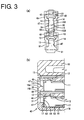
- FIGS. 3(a) and 3(b) are a partial enlarged front view and a partial enlarged section showing the state where the retainer is fully locked,
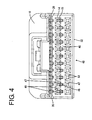
- FIG. 4 is a front view showing a state where the retainer is partly locked,
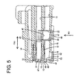
- FIG. 5 is a section showing the state where the retainer is partly locked,
- FIGS. 6(a) and 6(b) are a partial enlarged front view and a partial enlarged section showing the state where the retainer is partly locked,
- FIG. 7 is a section showing an intermediate state of mounting the retainer into a housing,
- FIG. 8 is a front view of the housing,
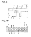
- FIG. 9 is a side view of the housing,
- FIG. 10 is a front view of the retainer,
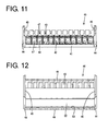
- FIG. 11 is a rear view of the retainer,
- FIG. 12 is a plan view of the retainer,
- FIG. 13 is a section of the retainer, and
- FIG. 14 is a bottom view of the retainer.
-
- Hereinafter, one preferred embodiment of the present invention is described with reference to FIGS. 1 to 14.
- A connector of this embodiment is comprised of a
housing 10, aretainer 40 and one or more femaleterminal fittings 30. In the following description, reference is made to FIGS. 1 to 3 concerning vertical direction and a mating side with an unillustrated mating connector (left side in FIG. 2) is referred to as front side concerning forward and backward directions. - The
housing 10 is internally formed with one or more, preferably a plurality ofcavities 11 arranged at one or more stages, preferably at two upper and lower stages, the same number ofcavities 11 preferably being transversely arrayed at a specified (predetermined or predeterminable) interval at each stage. Thesecavities 11 are narrow and long along forward and backward directions and are substantially open in the front and rear end surfaces of thehousing 10. Therespective cavities 11 at the upper stage and those at the lower stage are so arranged as to vertically substantially correspond to each other. - A front end portion of the lateral or ceiling wall of each
cavity 11 serves as a preferably cantilever-shapedlocking portion 12 preferably extending substantially forward. The upper surface of the lockingportion 12 of eachcavity 11 at the lower stage substantially faces the correspondingcavity 11 at the upper stage. Mold-removal spaces 13 formed by removing a mold for forming the lockingportions 12 are present before or at therespective locking portions 12 and open in the front end surface of thehousing 10. The front end surface of thehousing 10 is formed with (preferably substantially rectangular)insertion openings 14 for allowing the at least partial insertion of tabs of male terminal fittings (not shown) into thecavities 11 from front. Theinsertion openings 14 preferably have a width narrower than those of the mold-removal spaces 13 and thecavities 11, and are located above or adjacent to the bottom walls of thecavities 11. Therespective insertion openings 14 substantially communicate with the mold-removal spaces 13 located above theinsertion openings 14. - A housing-
side guiding portion 15 projects at the front end surface of thehousing 10 in such a manner as to extend substantially along the lateral or bottom side of the opening edge of theinsertion opening 14 of eachcavity 11 at the upper stage. This guidingportion 15 is formed with aguide surface 15A sloped down to the front from the bottom edge of theinsertion opening 14. The guidingportion 15 is also formed with an introducingsurface 15B sloped down to the back toward the upper side of the opening edge of the corresponding mold-removal space 13 at the lower stage. The lateral (left and right) surfaces of each guidingportion 15 are located at the substantially same positions as the lateral (left and right) sides of the opening edge of the corresponding insertion opening 14 with respect to transverse direction TD when viewed from front, and the lateral (left and right) surfaces of the guidingportion 15 serve as substantially flat guiding surfaces 16 (as preferred guiding means). - A narrow
accommodating portion 17 is formed preferably over the substantially entire width at the bottom end of the front end surface of thehousing 10. Thisaccommodating portion 17 substantially communicates with the bottom edges of theinsertion openings 14 of thecavities 11 at the lower stage, and the back end surface thereof is located at the substantially same position as front walls (wall surfaces for holding the female terminal fittings at their front-limit positions) of thecavities 11 along forward and backward directions FBD. In other words, substantially lower halves of thecavities 11 at the lower stage are substantially exposed at the front end surface of thehousing 10 by forming theaccommodating portion 17. - A
bottom wall 18 of thehousing 10 preferably serves also as or forms at least part of bottom walls of thecavities 11 at the lower stage, and is formed with a cut-awayportion 19 by having a front end portion thereof cut off. This cut-awayportion 19 is open up to the front end surface of thehousing 10 and substantially communicates with theaccommodating portion 17. It should be noted that the bottom wall and the lockingportions 12 are located on the surfaces substantially vertically opposed to each other in thecavities 11 at the lower stage. - The lateral (left and right) outer surfaces of the
housing 10 are lightly recessed to form mountingrecesses 20, which are open in the front end surface and the bottom surface of thehousing 10. One or more, preferably a pair of upper and lower, lockingprojections 21 are formed in each mountingrecess 20. - The
housing 10 is formed with amount space 22 which is open in the lateral or bottom surface of thehousing 10 and the mounting recesses 20. Thismount space 22 is used to at least partly accommodate theretainer 40 to be described later, penetrates thecavities 11 at an angle different from 0° or 180°, preferably substantially normal to the forward and backward directions FBD (preferably substantially vertically penetrates the cavities 11) or to an insertion direction ID of theterminal fittings 30 into therespective cavities 11 at the lower stage and communicates with thecavities 11 at the upper stage. - Each female terminal fitting 30 includes a (preferably substantially rectangular)
tube portion 31 at its front side and a wire connection portion, preferably comprising awire crimping portion 32, at its rear side. A first engagingportion 33 engageable with the lockingportion 12 is formed preferably on the upper surface of therectangular tube portion 31, and a second engaging portion 34 engageable with theretainer 40 is formed preferably at the rear bottom end of therectangular tube portion 31. Thewire crimping portion 32 is to be crimped or bent or folded into connection with awire 35. - The
retainer 40 includes a retainermain body 41 substantially narrow and long along transverse direction TD and to be at least partly accommodated in themount space 22 along a mounting direction MD. This retainermain body 41 is formed with (preferably substantially rectangular) terminal insertion holes 42 substantially corresponding to therespective cavities 11 at the lower stage, and lockingsections 43 engageable with the femaleterminal fittings 30 at least partly inserted or insertable in an inserting direction ID into thecavities 11 at the lower stage are formed on the bottom surfaces of the respective terminal insertion holes 42, whereas lockingsections 43 engageable with the femaleterminal fittings 30 at least partly inserted into thecavities 11 at the upper stage are formed on the upper surface of the retainermain body 41. - The
retainer 40 is formed with a pair of lateral (left and right) supportingportions 44 which are in the form of walls (substantially flat plates) obtained by elongating the lateral (left and right) walls of the retainermain body 41 in forward and backward directions FBD and/or vertical direction substantially in flush with the lateral (left and right) walls of the retainermain body 41. A lockingprojection 45 engageable with the corresponding lockingprojections 21 of thehousing 10 is formed on the inner side surface of each supportingportion 44. While being mounted in thehousing 10 such that most of the retainermain body 41 is accommodated in themount space 22, both supportingportions 44 are fitted in the mounting recesses 20, and each lockingprojection 45 is engaged between the corresponding pair of lockingprojections 21, theretainer 40 is held at a partial locking position (as a preferred first position) where the insertion and withdrawal of the femaleterminal fittings 30 into and from thecavities 11 are permitted (see FIGS. 4 to 6). - When the
retainer 40 is pushed up or moved in a mounting direction MD (being arranged at an angle different from 0° or 180°, preferably substantially perpendicular to the forward and backward directions FBD) to a full locking position (as a preferred second position) after the femaleterminal fittings 30 are substantially properly inserted into therespective cavities 11, the retainermain body 41 is preferably substantially completely accommodated in themount space 22 and therespective locking sections 43 come substantially into contact with the second engaging portions 34 of the femaleterminal fittings 30 from withdrawal side, preferably from behind, with the result that the femaleterminal fittings 30 are locked. At this time, the supportingportions 44 come substantially into contact with the upper edges of the mounting recesses 20 from below and the lockingprojections 45 come substantially into engagement with theupper locking projections 21, whereby theretainer 40 is held at the full locking position (see FIGS. 1 to 3). - A
front wall 46 preferably having a substantially rectangular front view spans between the front edges of the lateral (left and right) supportingportions 44. Thefront wall 46 is in the form of a substantially flat plate so as to be held substantially in close contact with the front end surface of thehousing 10, and slides substantially in contact with the front end surface of thehousing 10 when theretainer 40 is moved along the mounting direction MD or substantially vertically moved between the partial locking position and the full locking position. Thefront wall 46 is formed with (preferably substantially rectangular) throughholes 47 substantially facing (in alignment with) therespective insertion openings 14 when theretainer 40 is at the full locking position (second position). Preferably substantially rectangularjig insertion openings 48 substantially facing the mold-removal spaces 13 of thecavities 11 at the lower stage when theretainer 40 is at the partial locking position (position lower than or displaced along the mounting direction MD from the full locking position) penetrate thefront wall 46. The width of thejig insertion openings 48 preferably is substantially equal to that of the throughholes 47, and thejig insertion openings 48 communicating with the throughholes 47 corresponding to thecavities 11 at the upper stage. Tapered retainer-side guiding portions 49 are formed along one or more, preferably three, sides of the opening edge of each throughhole 47 corresponding to thecavity 11 at the upper stage excluding the lower side communicate with thejig insertion opening 48. Further, the lateral (left and right) inner surfaces of eachjig insertion opening 48 serve as substantially flat guiding surfaces 50 (as preferred guiding means) which come substantially into sliding contact with the guiding surfaces 16 of the corresponding housing-side guiding portion 15 of thehousing 10. It should be noted that retainer-side guiding portions 51 are formed preferably along all four sides of the opening edge of each throughhole 47 corresponding to thecavity 11 at the lower stage. - A reinforcing
wall 52 preferably substantially horizontally extending backward over the substantially entire width is formed at the bottom end of thefront wall 46. This reinforcingwall 52 projects substantially at an angle different from 0° or 180°, preferably substantially at a right angle to thefront wall 46, and the opposite lateral (left and right) ends thereof preferably are coupled to the bottom ends of the supportingportions 44. With theretainer 40 held at the full locking position (second position), the reinforcingwall 52 is at least partly accommodated in the cut-awayportion 19 of thehousing 10. In this state, the lower surface of the reinforcingwall 52 is substantially in flush with the lower surface of thebottom wall 18 of thehousing 10, and the upper surface of the front end of the reinforcingwall 52 substantially faces the front ends of thecavities 11 at the lower stage from below. In other words, the upper surface of the front end of the reinforcingwall 52 forms a part of the bottom walls of thecavities 11. - A bulging
portion 53 is formed preferably over the substantially entire width at an inner corner portion where thefront wall 46 and the reinforcingwall 52 meet at right angles, thereby increasing the thicknesses of thefront wall 46 and the reinforcingwall 52. This bulgingportion 53 projects backward from thefront wall 46 and projects upward from the reinforcingwall 52. In other words, the bulgingportion 53 is provided at a position adjacent thefront wall 46 and the reinforcingwall 52 so as to connect them. With theretainer 40 held at the full locking position (second position), the bulgingportion 53 is at least partly accommodated in theaccommodating portion 17 of thehousing 10 and the rear surface thereof substantially faces thecavities 11 at the lower stage from front. In other words, the bulgingportion 53 forms a part of the front walls of thecavities 11. - Next, the functions of this embodiment are described.
- Upon assembling the connector, the
retainer 40 is first mounted at the partial locking position (first position) in thehousing 10. Specifically, theretainer 40 is brought closer to thehousing 10 in the mounting direction MD; preferably from below; the supportingportions 44 are at least partly fitted into the mounting recesses 20; the retainermain body 41 is at least partly fitted into themount space 22; and/or thefront wall 46 is brought substantially into sliding contact with the front end surface of thehousing 10. After the upper end of thefront wall 46 moves preferably onto the housing-side guiding portions 15 to thereby undergo a slight forward resilient deformation (see FIG. 7), theretainer 40 is mounted at the partial locking position (first position). - In this state, the
respective insertion openings 14 of thehousing 10 are at least partly closed by thefront wall 46 of theretainer 40; the mold-removal spaces 13 at the upper stage are substantially exposed to the outside since being located above the upper edges of thefront wall 46; and the mold-removal spaces 13 at the lower stage are substantially exposed to the outside via thejig insertion openings 48 communicating with the throughholes 47 at the upper stage. Further, the throughholes 47 at the upper stage are engaged with the housing-side guiding portions 15. - With the
retainer 40 held at the partial locking position (first position) in this way, the femaleterminal fittings 30 are or can be at least partly inserted into therespective cavities 11 in the insertion direction ID or along the forward and backward direction FBD. The inserted femaleterminal fittings 30 are preferably locked by the engagement of the lockingportions 12 with the first engagingportions 33. - The
retainer 40 is moved in the mounting direction MD to the full locking position (second position) after the insertion of all the femaleterminal fittings 30 is completed. As theretainer 40 is moved, thefront wall 46 slides along the front end surface of thehousing 10. At this time, thefront wall 46 is guided by the sliding contact of the guiding surfaces 16 of the housing-side guiding portions 15 and the guiding surfaces 50 of thejig insertion openings 48. When theretainer 40 reaches the full locking position, the throughholes 47 of theretainer 40 are substantially aligned with theinsertion openings 14; the mold-removal spaces 13 at the upper stage are substantially closed by the upper end of thefront wall 46; and the mold-removal spaces 13 at the lower stage are substantially closed by portions of thefront wall 46 located between thejig insertion openings 48 and the throughholes 47 at the lower stage. - Further, the front ends of the
cavities 11 at the lower stage exposed downward are preferably substantially closed by the engagement of the reinforcingwall 52 with the cut-awayportion 19 of thehousing 10, and the front end surfaces of the femaleterminal fittings 30 at least partly inserted into thecavities 11 at the lower stage are stopped by the bulgingportion 53 so as not to move any further forward by the engagement of the bulgingportion 53 with theaccommodating portion 17. Further, the lockingsections 43 of theretainer 40 are engaged with the second engaging portions 34 of the femaleterminal fittings 30. In this way, the femaleterminal fittings 30 are securely (preferably doubly) locked by the lockingportions 12 and/or theretainer 40. - With the
retainer 40 held at the full locking position (second position), the retainer-side guiding portions 49 are located preferably at three (the upper, left and right) sides of the opening edges of the through holes 47 (preferably at the upper stage) and the housing-side guiding portions 15 are located at the remaining (preferably bottom) sides. In other words, the tapered guiding portions preferably are formed over the substantially entire circumference of the opening edge of each throughhole 47 at the upper stage. Accordingly, even if the tab of the male terminal fitting is displaced to up, down, left and/or right while being inserted into thecavity 11, this tab can be introduced to the middle by being brought substantially into sliding contact with these guidingportions hole 47 and theinsertion opening 14. It should be noted that the retainer-side guiding portions 51 are formed preferably over the substantially entire circumference of each throughhole 47 at the lower stage. - Upon withdrawing the female
terminal fittings 30, theretainer 40 is first moved to the partial locking position (first position) to disengage the lockingsections 43 from the second engaging portions 34 of the femaleterminal fittings 30, thereby canceling the locking of the femaleterminal fittings 30 by theretainer 40. By moving theretainer 40, the mold-removal spaces 13 are substantially exposed forward via thejig insertion openings 48. Then, a narrow jig (not shown) is at least partly inserted into thejig insertion opening 48 to resiliently deform the lockingportion 12 away from the terminal fitting 30, preferably substantially upward, i.e. in a disengaging direction from the first engagingportion 33, thereby canceling the locking of the terminal fitting 30 by the lockingportion 12. Thereafter, the female terminal fitting 30 may be pulled in a withdrawing direction, preferably substantially backward while maintaining this state. - As described above, in this embodiment, the
front wall 46 is formed with the throughholes 47 facing theinsertion opening 14 at the upper stage with theretainer 40 held at the full locking position and thejig insertion openings 48 facing the mold-removal spaces 13 at the lower stage with theretainer 40 held at the partial locking position (first position). The slanted guide surfaces are formed preferably over the substantially entire opening edges of the through holes 47 (preferably at the upper stage) by the retainer-side guiding portions 49 and the housing-side guiding portions 15, whereby the tabs of the male terminal fittings (as preferred portions of a mating connector) can be securely guided to theinsertion openings 14. - Further, the guiding surfaces 16, 50 which can be brought substantially into sliding contact with each other and are substantially parallel with the sliding direction MD of the
front wall 46 as theretainer 40 is displaced are provided on the housing-side guiding portions 15 and at the opening edges of thejig insertion openings 48, respectively. Thefront wall 46 can be moved along a specified path by the sliding contact of these guidingsurfaces - Furthermore, the surfaces of the housing-
side guiding portions 15 substantially opposite from theinsertion openings 14 at one stage (e.g. at the upper stage) are formed into the slanted introducingsurfaces 15B facing the opening edges of thejig insertion openings 48 for theadjacent cavities 11 at an adjacent stage (e.g. at the lower stage). Thus, the jig can be securely inserted into thejig insertion opening 48. - There is a possibility that the
front wall 46 undergoes such a deformation as to be curved along forward and backward directions since being supported at the front ends of the two supportingportions 44. However, in this embodiment, thefront wall 46 is formed with the reinforcingwall 52 at an angle different from 0° or 180°, preferably substantially normal to the wall surface of thefront wall 46 and extending in transverse direction, which prevents thefront wall 46 from being curved along forward and backward directions. - Further, since the opposite left and right edges of the reinforcing
wall 52 are coupled to the supportingportions 44, displacements of the reinforcingwall 52 can be restricted, with the result that the deformation of thefront wall 46 can be more securely prevented. - Furthermore, since the reinforcing
wall 52 is accommodated in the cut-awayportion 19 formed in thebottom wall 18 of thehousing 10, it does not project out from the outer surface of thehousing 10 with theretainer 40 held at the full locking position. - Further, since the locking
portions 12 are located at the side (upper side) opposite from the cut-awayportion 19 in thecavities 11 at the lower stage where the cut-awayportion 19 is formed, the reinforcingwall 52 engaged with the cut-awayportion 19 does not interfere with the lockingportions 12. - Further, since the bulging
portion 53 is formed to partially increase the thicknesses of thefront wall 46 and the reinforcingwall 52 at the corner portion where thefront wall 46 and the reinforcingwall 52 meet or join, thefront wall 46 and the reinforcingwall 52 have a higher bending strength. - Furthermore, the bulging
portion 53 for holding the femaleterminal fittings 30 at least partly inserted into thecavities 11 at the lower stage at their front-limit positions and the lockingsections 43 for locking the femaleterminal fittings 30 are constantly spaced apart by a specified distance along forward and backward directions since being both formed in theretainer 40. Thus, even if theretainer 40 shakes along forward and backward directions with respect to thehousing 10 due to a dimensional tolerance or the like, the femaleterminal fittings 30 held at their front-limit positions by the bulgingportion 53 do not shake forward and backward with respect to theretainer 40. - Accordingly, to enable portions of mating terminal fittings (preferably tabs of male terminal fittings) to be securely guided into cavities, one or more tapered retainer-
side guiding portions 49 are formed at least partly at opening edges of throughholes 47 preferably excluding their communicating areas with correspondingjig insertion openings 48, and the front end surface of ahousing 10 is formed with slanted housing-side guiding portions 15 which are located in the communicating areas of the opening edges of the throughholes 47 with thejig insertion openings 48 with aretainer 40 held at a full locking position. Even if the throughholes 47 communicate with thejig insertion openings 48 for theadjacent cavities 11 at the lower stage, slanted guiding surfaces are formed over the entire circumferences of the opening edges of the throughholes 47 by the retainer-side guiding portions 49 and the housing-side guiding portions 15. Thus, tabs of male terminal fittings can be securely guided toinsertion openings 14. - The present invention is not limited to the above described and illustrated embodiment. For example, the following embodiments are also embraced by the technical scope of the present invention as defined by the claims. Beside the following embodiments, various changes can be made without departing from the scope and spirit of the present invention as defined by the claims.
- (1) Although both the housing-side guiding portions and the opening edges of the jig insertion openings are formed with the guiding surfaces substantially parallel with the sliding direction of the front wall and/or the mounting direction MD as the guiding means in the foregoing embodiment, the guiding surfaces substantially parallel with the sliding direction of the front wall may be formed at either one of the housing-side guiding portions and the opening edges of the jig insertion openings according to the present invention.
- (2) Although the cavities are arrayed at the two upper and lower stages in the foregoing embodiment, the present invention is also applicable to connectors in which cavities are arrayed at one or at three or more stages.
-
-
- 10
- housing
- 11
- cavity
- 12
- locking portion
- 13
- mold-removal space
- 14
- insertion opening
- 15
- housing-side guiding portion
- 15B
- introducing surface
- 16
- guiding surface (guiding means)
- 30
- female terminal fitting
- 40
- retainer
- 46
- front wall
- 47
- through hole
- 48
- jig insertion opening
- 49
- retainer-side guiding portion
- 50
- guiding surface (guiding means)
Claims (10)
- A connector in which:wherein:one or more cavities (11) and one or more locking portions (12) are formed inside a housing (10),the front end surface of the housing (10) is formed with one or more insertion openings (14) through which portions of mating terminal fittings are at least partly insertable into the cavities (11) and one or more mold-removal spaces (13) left as a mold for forming the locking portions (12) is removed,a terminal fitting (30) at least partly inserted into the cavity (11) is locked by the engagement with the locking portion (12), and is permitted to be withdrawn from the cavity (11) by disengaging the locking portion (12) from the terminal fitting (30) by means of a jig at least partly insertable into the mold-removal space (13),a retainer (40) displaceable in a direction (MD) intersecting with an inserting direction (ID) of the terminal fittings (30) between a first position (FIG. 4; 6) where the insertion and withdrawal of the terminal fittings (30) are permitted and a second position (FIG. 1; 3) where the retainer (30) engages the inserted terminal fittings (30) to lock the terminal fittings (30) is at least partly mountable into the housing (10),the retainer (40) is formed with a front wall (46) slidable at least partly substantially along the front end surface of the housing (10), andthe front wall (46) is formed with one or more through holes (47) which substantially face the insertion openings (14) with the retainer (40) held at the second position and one or more jig insertion openings (48) which substantially face the mold-removal spaces (13) with the retainer (40) held at the first position,a tapered retainer-side guiding portion (49) is at least partly formed in an area of the opening edge of each through hole (47), andthe front end surface of the housing (10) is formed with one or more tapered housing-side guiding portions (15).
- A connector according to claim 1, wherein the corresponding through holes (47) and jig insertion openings (48) communicating with each other.
- A connector according to claim 2, wherein tapered retainer-side guiding portion (49) is formed in an area of the opening edge of each through hole (47) excluding a communicating area with the corresponding jig insertion opening (48).
- A connector according to claim 2 or 3, wherein the tapered housing-side guiding portions (15) are located at the communicating areas of the opening edges of the through holes (47) with the jig insertion openings (48) with the retainer (40) held at the second position.
- A connector according to one or more of the preceding claims, wherein guiding means (16; 50) which can be brought substantially into sliding contact with each other and at least one of which is substantially parallel with a sliding direction (MD) of the front wall (46) as the retainer (40) is displaced are provided at each housing-side guiding portion (15) and the opening edge of the corresponding jig insertion opening (48).
- A connector according to one or more of the preceding claims, wherein a surface of preferably each housing-side guiding portion (15) substantially opposite from the corresponding insertion opening (14) serves as a slanted introducing surface (15B) substantially facing the opening edge of the jig insertion opening (48) for the other adjacent cavity.
- A connector according to one or more of the preceding claims, wherein the front wall (46) is formed with at least one reinforcing portion (52) projecting in a direction at an angle different from 0° or 180°, preferably substantially normal to a wall surface of the front wall (46) and extending substantially in transverse direction (TD).
- A method of connecting a connector with a mating connector, comprising the following steps:wherein a portion of the mating connector is guidedproviding a connector having one or more cavities (11) and one or more locking portions (12) are formed inside a housing (10), the front end surface of the housing (10) is formed with one or more insertion openings (14) through which portions of mating terminal fittings are at least partly insertable into the cavities (11) and one or more mold-removal spaces (13) left as a mold for forming the locking portions (12) is removed,at least partly inserting a terminal fitting (30) into the cavity (11) and locking the terminal fitting (30) by the engagement with the locking portion (12), and is permitted to be withdrawn from the cavity (11) by disengaging the locking portion (12) from the terminal fitting (30) by means of a jig at least partly insertable into the mold-removal space (13),at least partly mounting a retainer (40) into the housing (10) so as to be displaceable in a direction (MD) intersecting with an inserting direction (ID) of the terminal fittings (30) between a first position (FIG. 4; 6) where the insertion and withdrawal of the terminal fittings (30) are permitted and a second position (FIG. 1; 3) where the retainer (30) engages the inserted terminal fittings (30) to lock the terminal fittings (30), wherein the retainer (40) is formed with a front wall (46) slidable at least partly substantially along the front end surface of the housing (10), andarranging one or more through holes (47) of the front wall (46) so as to substantially face the insertion openings (14) with the retainer (40) held at the second position andarranging one or more jig insertion openings (48) of the front wall (46) so as to substantially face the mold-removal spaces (13) with the retainer (40) held at the first position,by a tapered retainer-side guiding portion (49) being at least partly formed in an area of the opening edge of each through hole (47), andby one or more tapered housing-side guiding portions (15) being formed at or on the front end surface of the housing (10).
- A method according to claim 8, wherein the corresponding through holes (47) and jig insertion openings (48) are formed such as to communicate with each other.
- A method according to claim 9, wherein tapered retainer-side guiding portion (49) is formed in an area of the opening edge of each through hole (47) excluding a communicating area with the corresponding jig insertion opening (48) and/or wherein the tapered housing-side guiding portions (15) are provided so as to be located at the communicating areas of the opening edges of the through holes (47) with the jig insertion openings (48) with the retainer (40) held at the second position.
Applications Claiming Priority (2)
| Application Number | Priority Date | Filing Date | Title |
|---|---|---|---|
| JP2002316520A JP2004152621A (en) | 2002-10-30 | 2002-10-30 | Connector |
| JP2002316520 | 2002-10-30 |
Publications (2)
| Publication Number | Publication Date |
|---|---|
| EP1416592A1 true EP1416592A1 (en) | 2004-05-06 |
| EP1416592B1 EP1416592B1 (en) | 2006-04-05 |
Family
ID=32089542
Family Applications (1)
| Application Number | Title | Priority Date | Filing Date |
|---|---|---|---|
| EP03024975A Expired - Lifetime EP1416592B1 (en) | 2002-10-30 | 2003-10-29 | A connector and method of connecting a connector with a mating connector |
Country Status (3)
| Country | Link |
|---|---|
| US (1) | US6835105B1 (en) |
| EP (1) | EP1416592B1 (en) |
| JP (1) | JP2004152621A (en) |
Cited By (1)
| Publication number | Priority date | Publication date | Assignee | Title |
|---|---|---|---|---|
| EP2381540A4 (en) * | 2009-01-20 | 2013-11-27 | Yazaki Corp | CONNECTOR |
Families Citing this family (7)
| Publication number | Priority date | Publication date | Assignee | Title |
|---|---|---|---|---|
| JP4904131B2 (en) * | 2006-11-20 | 2012-03-28 | 矢崎総業株式会社 | connector |
| JP5394696B2 (en) * | 2008-11-05 | 2014-01-22 | 矢崎総業株式会社 | connector |
| JP2009218224A (en) * | 2009-06-19 | 2009-09-24 | Fci Connectors Singapore Pte Ltd | Connector |
| JP5533625B2 (en) * | 2010-12-16 | 2014-06-25 | 住友電装株式会社 | connector |
| US8721374B2 (en) * | 2011-07-22 | 2014-05-13 | Lear Corporation | Electrical connector |
| US8951066B2 (en) | 2011-07-22 | 2015-02-10 | Lear Corporation | Electrical connector |
| JP7666317B2 (en) * | 2021-12-17 | 2025-04-22 | 住友電装株式会社 | connector |
Citations (2)
| Publication number | Priority date | Publication date | Assignee | Title |
|---|---|---|---|---|
| US6080023A (en) * | 1995-09-01 | 2000-06-27 | Tyco Electronics Logistics Ag | Electrical connector with a contact-ensuring slide |
| EP1150388A2 (en) * | 2000-04-28 | 2001-10-31 | Sumitomo Wiring Systems, Ltd. | A shake preventing construction for a terminal fitting and connector |
Family Cites Families (10)
| Publication number | Priority date | Publication date | Assignee | Title |
|---|---|---|---|---|
| US5203722A (en) | 1990-09-28 | 1993-04-20 | Amp Incorporated | Double-lock electrical connector |
| US5439397A (en) | 1990-10-01 | 1995-08-08 | Yazaki Corporation | Connector |
| US5183418A (en) | 1990-10-01 | 1993-02-02 | Yazaki Corporation | Connector |
| JPH07226251A (en) * | 1994-02-09 | 1995-08-22 | Amp Japan Ltd | Lock type connector |
| JP2916576B2 (en) * | 1994-07-22 | 1999-07-05 | 矢崎総業株式会社 | ID connector |
| JP3330506B2 (en) * | 1997-03-10 | 2002-09-30 | 矢崎総業株式会社 | connector |
| JP3753019B2 (en) * | 2001-06-15 | 2006-03-08 | 住友電装株式会社 | connector |
| JP3755431B2 (en) * | 2001-06-22 | 2006-03-15 | 住友電装株式会社 | connector |
| DE10227347B4 (en) * | 2001-06-22 | 2009-03-05 | Sumitomo Wiring Systems, Ltd., Yokkaichi | Interconnects |
| DE10227334B4 (en) * | 2001-06-22 | 2009-02-12 | Sumitomo Wiring Systems, Ltd., Yokkaichi | Interconnects |
-
2002
- 2002-10-30 JP JP2002316520A patent/JP2004152621A/en not_active Abandoned
-
2003
- 2003-10-29 EP EP03024975A patent/EP1416592B1/en not_active Expired - Lifetime
- 2003-10-29 US US10/696,435 patent/US6835105B1/en not_active Expired - Fee Related
Patent Citations (2)
| Publication number | Priority date | Publication date | Assignee | Title |
|---|---|---|---|---|
| US6080023A (en) * | 1995-09-01 | 2000-06-27 | Tyco Electronics Logistics Ag | Electrical connector with a contact-ensuring slide |
| EP1150388A2 (en) * | 2000-04-28 | 2001-10-31 | Sumitomo Wiring Systems, Ltd. | A shake preventing construction for a terminal fitting and connector |
Cited By (1)
| Publication number | Priority date | Publication date | Assignee | Title |
|---|---|---|---|---|
| EP2381540A4 (en) * | 2009-01-20 | 2013-11-27 | Yazaki Corp | CONNECTOR |
Also Published As
| Publication number | Publication date |
|---|---|
| EP1416592B1 (en) | 2006-04-05 |
| JP2004152621A (en) | 2004-05-27 |
| US6835105B1 (en) | 2004-12-28 |
Similar Documents
| Publication | Publication Date | Title |
|---|---|---|
| US7500887B2 (en) | Connector and method of assembling it | |
| EP1271705B1 (en) | Connector with open-stopping means for retainer | |
| US7204725B2 (en) | Connector and method of assembling it | |
| EP1416593B1 (en) | A connector | |
| EP1923962A1 (en) | A connector and method of preassembling it | |
| EP0978905B1 (en) | Connector | |
| US20020193013A1 (en) | Connector | |
| EP1303009B1 (en) | A cover, a joint connector and a method for mounting a joint connector | |
| JP3317390B2 (en) | connector | |
| US20020193012A1 (en) | Connector and a method of assembling it | |
| EP0905819B1 (en) | A connector provided with a retainer | |
| EP1416592B1 (en) | A connector and method of connecting a connector with a mating connector | |
| US6592411B2 (en) | Connector | |
| EP1172895B1 (en) | Connector | |
| US6645015B2 (en) | Connector with housing and retainer mounted to front of housing | |
| US6702628B2 (en) | Connector and a method of assembling it | |
| US20060073739A1 (en) | Connector | |
| US6695651B2 (en) | Connector | |
| US6589083B2 (en) | Connector | |
| US6488547B2 (en) | Connector with longitudinally spaced locks for retaining terminal fittings | |
| EP1376770B1 (en) | A connector and a method of assembling it | |
| US6659798B2 (en) | Connector | |
| EP1150388B1 (en) | A shake preventing construction for a terminal fitting and connector | |
| JP3193271B2 (en) | connector | |
| JP2002270275A (en) | Connector |
Legal Events
| Date | Code | Title | Description |
|---|---|---|---|
| PUAI | Public reference made under article 153(3) epc to a published international application that has entered the european phase |
Free format text: ORIGINAL CODE: 0009012 |
|
| 17P | Request for examination filed |
Effective date: 20031120 |
|
| AK | Designated contracting states |
Kind code of ref document: A1 Designated state(s): AT BE BG CH CY CZ DE DK EE ES FI FR GB GR HU IE IT LI LU MC NL PT RO SE SI SK TR |
|
| AX | Request for extension of the european patent |
Extension state: AL LT LV MK |
|
| AKX | Designation fees paid |
Designated state(s): FR |
|
| REG | Reference to a national code |
Ref country code: DE Ref legal event code: 8566 |
|
| 17Q | First examination report despatched |
Effective date: 20050531 |
|
| GRAP | Despatch of communication of intention to grant a patent |
Free format text: ORIGINAL CODE: EPIDOSNIGR1 |
|
| GRAS | Grant fee paid |
Free format text: ORIGINAL CODE: EPIDOSNIGR3 |
|
| GRAA | (expected) grant |
Free format text: ORIGINAL CODE: 0009210 |
|
| AK | Designated contracting states |
Kind code of ref document: B1 Designated state(s): FR |
|
| ET | Fr: translation filed | ||
| PLBE | No opposition filed within time limit |
Free format text: ORIGINAL CODE: 0009261 |
|
| STAA | Information on the status of an ep patent application or granted ep patent |
Free format text: STATUS: NO OPPOSITION FILED WITHIN TIME LIMIT |
|
| 26N | No opposition filed |
Effective date: 20070108 |
|
| PGFP | Annual fee paid to national office [announced via postgrant information from national office to epo] |
Ref country code: FR Payment date: 20131009 Year of fee payment: 11 |
|
| REG | Reference to a national code |
Ref country code: FR Ref legal event code: ST Effective date: 20150630 |
|
| PG25 | Lapsed in a contracting state [announced via postgrant information from national office to epo] |
Ref country code: FR Free format text: LAPSE BECAUSE OF NON-PAYMENT OF DUE FEES Effective date: 20141031 |