EP1416559A2 - Fuel cell stack with heat exchanger - Google Patents
Fuel cell stack with heat exchanger Download PDFInfo
- Publication number
- EP1416559A2 EP1416559A2 EP03256185A EP03256185A EP1416559A2 EP 1416559 A2 EP1416559 A2 EP 1416559A2 EP 03256185 A EP03256185 A EP 03256185A EP 03256185 A EP03256185 A EP 03256185A EP 1416559 A2 EP1416559 A2 EP 1416559A2
- Authority
- EP
- European Patent Office
- Prior art keywords
- fuel cell
- cell stack
- heat exchanger
- gas
- fuel
- Prior art date
- Legal status (The legal status is an assumption and is not a legal conclusion. Google has not performed a legal analysis and makes no representation as to the accuracy of the status listed.)
- Withdrawn
Links
Images


Classifications
-
- H—ELECTRICITY
- H01—ELECTRIC ELEMENTS
- H01M—PROCESSES OR MEANS, e.g. BATTERIES, FOR THE DIRECT CONVERSION OF CHEMICAL ENERGY INTO ELECTRICAL ENERGY
- H01M8/00—Fuel cells; Manufacture thereof
- H01M8/04—Auxiliary arrangements, e.g. for control of pressure or for circulation of fluids
- H01M8/04007—Auxiliary arrangements, e.g. for control of pressure or for circulation of fluids related to heat exchange
- H01M8/04014—Heat exchange using gaseous fluids; Heat exchange by combustion of reactants
-
- H—ELECTRICITY
- H01—ELECTRIC ELEMENTS
- H01M—PROCESSES OR MEANS, e.g. BATTERIES, FOR THE DIRECT CONVERSION OF CHEMICAL ENERGY INTO ELECTRICAL ENERGY
- H01M8/00—Fuel cells; Manufacture thereof
- H01M8/24—Grouping of fuel cells, e.g. stacking of fuel cells
- H01M8/2465—Details of groupings of fuel cells
- H01M8/247—Arrangements for tightening a stack, for accommodation of a stack in a tank or for assembling different tanks
- H01M8/2475—Enclosures, casings or containers of fuel cell stacks
-
- Y—GENERAL TAGGING OF NEW TECHNOLOGICAL DEVELOPMENTS; GENERAL TAGGING OF CROSS-SECTIONAL TECHNOLOGIES SPANNING OVER SEVERAL SECTIONS OF THE IPC; TECHNICAL SUBJECTS COVERED BY FORMER USPC CROSS-REFERENCE ART COLLECTIONS [XRACs] AND DIGESTS
- Y02—TECHNOLOGIES OR APPLICATIONS FOR MITIGATION OR ADAPTATION AGAINST CLIMATE CHANGE
- Y02E—REDUCTION OF GREENHOUSE GAS [GHG] EMISSIONS, RELATED TO ENERGY GENERATION, TRANSMISSION OR DISTRIBUTION
- Y02E60/00—Enabling technologies; Technologies with a potential or indirect contribution to GHG emissions mitigation
- Y02E60/30—Hydrogen technology
- Y02E60/50—Fuel cells
Definitions
- the present invention relates generally to fuel cells, and more particularly to fuel cell stacks with heat exchangers.
- Fuel cells use an electrochemical energy conversion of hydrogen and oxygen into electricity and heat. It is anticipated that fuel cells may be able to replace primary and secondary batteries as a portable power supply. In, for example, solid oxide fuel cells, the oxygen reduction reaction (taking place at the cathode) is: O 2 + 4 e - ⁇ 2O 2- .
- the O 2- ion is transferred from the cathode through the electrolyte to the anode.
- Some typical fuel oxidation reactions (taking place at the anode) are: 2H 2 + 2O 2- ⁇ 2H 2 O + 4 e - 2CO + 2O 2- ⁇ 2CO 2 + 4 e - .
- fuel cells provide a direct current (DC) voltage that may be used to power motors, lights, electrical appliances, etc.
- a solid oxide fuel cell (SOFC) is a type of fuel cell that may be useful in portable applications. SOFCs generally require somewhat high temperature environments for efficient operation. As such, it is desirable for SOFCs to reach operating temperatures in an efficient and rapid manner.
- the present invention solves the drawbacks enumerated above by providing a fuel cell which includes a fuel cell stack and a heat exchanger in fluid and thermal communication with the fuel cell stack.
- the heat exchanger is adjacent the fuel cell stack and both removes excess heat from the fuel cell stack and preheats a gas before entry into the fuel cell stack.
- the present invention is predicated upon the unexpected and fortuitous discovery that performance of a fuel cell may be improved by using heat generated during operation of the fuel cell stack (as opposed to exhaust gas heat) to warm incoming gas (oxidant(s) and/or reactant(s)) to more efficient operating temperatures.
- This removal of heat from the fuel cell stack advantageously substantially prevents overheating of the fuel cell stack. As such, the deleterious effects of fuel cell stack overheating (for example, cracking or other thermal damage) are substantially avoided.
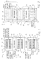
- Fuel cell 10, 10', 10" comprises a fuel cell stack 12, 12', 12" and a heat exchanger 14, 24' in fluid and thermal communication with the fuel cell stack 12, 12', 12".
- the heat exchanger 14, 24' is adjacent the fuel cell stack 12, 12', 12" and is adapted to both remove excess heat from the fuel cell stack 12, 12', 12" and preheat a gas before entry into the fuel cell stack 12, 12', 12".
- each fuel cell stack 12, 12', 12" may comprise any desired number of fuel cell assemblies (anode 46, cathode 48, electrolyte 50). Still further, it is to be understood that there may be one or a plurality of heat exchangers 14, 14', 24, 24', as desired and/or necessitated by a chosen end use.
- the fuel cell 10, 10', 10" may optionally comprise a port 16, 16', in fluid communication with the heat exchanger 14, 24' for adding water and/or water vapor to the gas before entry into the fuel cell stack 12, 12', 12".
- the gas may be carried in a conduit 20 (Figs. 1 and 5), 20' (Fig. 3) to the heat exchanger 14, 24'; however, it is to be understood that the gas may be carried to heat exchanger 14, 24' in many ways.
- Fuel cell 10, 10', 10" in addition to port 16, 16', or alternate to port 16, 16', may optionally comprise a port 18, 18' in fluid communication with the conduit 20, 20', for adding water and/or water vapor to the gas before entry into the heat exchanger 14, 24'.
- the addition of water/water vapor to the fuel (in a dual chamber embodiment, Figs. 3 and 4) or to the fuel/air mixture (in a single chamber embodiment, Figs. 1, 2 and 5), may be advantageous in that it allows partial reforming of the fuel before entry into the fuel cell stack 12, 12', 12". This may assist in enhancing the reforming reaction, which may in turn help improve fuel utilization and increase power output.
- a further advantage gained from the addition of water/water vapor is that the endothermic reforming reaction may aid in cooling certain high temperature portions of the stack 12, 12', 12" eg. near the gas inlet 22 (Fig. 2), 22' (Fig. 3).
- the fuel cell 10, 10', 10" may further optionally comprise a manifold, represented schematically by arrows 26, 26', operatively and fluidly connected between the heat exchanger 14, 24' and the fuel cell stack 12, 12', 12" for adding non-reacted/fresh gas in an area downstream from the fuel cell stack inlet 22, 22'.
- Downstream is defined herein as meaning past at least one fuel cell assembly (anode 46/cathode 48/electrolyte 50) from inlet 22, 22'.
- the gas comprises reactants and/or oxidants and/or mixtures thereof.
- the reactants are fuels
- the oxidants are one of oxygen, air, and mixtures thereof.
- any suitable fuel/reactant may be used with the fuel cell 10, 10', 10" of the present invention.
- the fuel/reactant is selected from at least one of methane, ethane, propane, butane, pentane, methanol, ethanol, higher straight chain or mixed hydrocarbons, for example, natural gas or gasoline (low sulfur hydrocarbons may be desirable, eg. low sulfur gasoline, low sulfur kerosene, low sulfur diesel), and mixtures thereof.
- the fuel/reactant is selected from the group consisting of butane, propane, methane, pentane, and mixtures thereof. Suitable fuels may be chosen for their suitability for internal and/or direct reformation, suitable vapor pressure within the operating temperature range of interest, and like parameters.
- the fuel cell 10, 10', 10" may be one of solid oxide fuel cells (SOFCs), proton conducting ceramic fuel cells, Polymer Electrolyte Membrane (PEM) fuel cells, molten carbonate fuel cells, solid acid fuel cells, and Direct Methanol PEM fuel cells.
- SOFCs solid oxide fuel cells
- PEM Polymer Electrolyte Membrane
- molten carbonate fuel cells solid acid fuel cells
- Direct Methanol PEM fuel cells Direct Methanol PEM fuel cells.
- the fuel cell 10, 10', 10" is a solid oxide fuel cell. Without being bound to any theory, it is believed that some added advantages may be gained when using a solid oxide fuel cell in conjunction with the present invention.
- SOFCs generally require a mechanism in which the fuel, air and/or fuel/air mixture are/is brought substantially up to operating temperature; otherwise cooling and/or non-uniform heating of the cell 10, 10', 10" may result in deleterious stress related damage, and in some instances, lower overall performance.
- a heat exchanger gas flow path/passage is schematically shown and designated as 28.
- a fuel cell stack gas flow path is schematically shown and designated as 30.
- the heat exchanger gas flow path 28 is substantially orthogonal to the fuel cell stack gas flow path 30. This gas flow arrangement is advantageous in that it allows efficient heat transfer under certain predetermined conditions.
- gas flow arrangement in embodiments of the present invention may be otherwise, as desired and/or necessitated by a particular end use and/or packaging constraints.
- a heat exchanger oxidant/air flow path is schematically shown and designated as 32.
- a heat exchanger reactant/fuel flow path is schematically shown and designated as 32'.
- a fuel cell stack reactant/fuel flow path is schematically shown and designated as 34.
- a fuel cell stack oxidant/air flow path is schematically shown and designated as 34'.
- the gas flow paths 32, 32' and 34, 34' run substantially parallel to each other.
- the fuel cell 10, 10', 10" of embodiments of the present invention may further optionally comprise a housing 36, 36' containing the fuel cell stack(s) 12, 12'.
- the heat exchanger(s) 14, 14', 24, 24' is/are formed, unitarily or otherwise, from the housing 36, 36'. It is to be understood that housing 36, 36' may be formed in any suitable size, shape and/or configuration, as desired and/or necessitated by a particular end use and/or packaging constraints.
- housing 36, 36' may be formed from any suitable material and by any suitable process.
- housing 36, 36' is formed from a high thermal conductivity material.
- the high thermal conductivity material may comprise any suitable material.
- the high thermal conductivity material is selected from at least one of stainless steel with low nickel concentrations (for example, HAYNES® Ti-3Al-2.5V alloy, Type 446, and the like), stainless steel, metallic alloys coated with an unreactive layer, aluminum oxide, magnesium oxide, carbon materials, silicon, single crystal silicon, polycrystalline silicon, silicon oxide, alumina, sapphire, ceramic, and mixtures thereof.
- the metallic alloys include but are not limited to high temperature nickel alloys, eg.
- Some such alloys are commercially available under the tradenames INCONEL 600 and INCONEL 601 from International Nickel Company in Wexford, Pennsylvania, and HASTELLOY X and HA-230 from Haynes International, Inc. in Kokomo, Indiana.
- Some non-limitative carbon materials include graphite, diamond, and the like.
- Fuel cell 10, 10' may further optionally comprise insulation disposed about the housing for substantially preventing undesirable heat loss to the surrounding environment.
- this insulation may comprise any suitable material; however, in an embodiment, the insulation is formed from at least one of advanced aerogel insulation, multilayer foil insulation, thermal barrier materials, and mixtures thereof. Aerogels have an extremely fine and highly porous structure, are very light, and may be made from various materials including silica, alumina, titania, hafnium carbide, and a variety of polymers. An example of a suitable aerogel is commercially available under the tradename PYROGEL® from Aspen Systems, Inc. in Marlborough, Massachusetts. PYROGEL is refractory oxide and carbide aerogel insulation useful at temperatures up to about 3000°C.
- any of the heat exchangers 14, 14', 24, 24' disclosed herein may optionally comprise a heat transfer enhancement member 37.
- member 37 may comprise any suitable structure and/or material, as desired and/or necessitated by a particular end use.
- member 37 is selected from at least one of fins 38, posts, foams, and combinations thereof. Fins 38 extend outwardly from the heat exchanger 14, 14', 24, 24' toward the fuel cell stack 12, 12', 12". The fins 38 are adapted to aid in conductive heat transfer between the fuel cell stack 12, 12', 12" and the heat exchanger 14, 14', 24, 24'.
- the fuel cell stack 12, 12', 12", 40, 40', 42 have a surface area greater than the surface area of the substrate upon which it is built.
- housing 36, 36' may be the substrate upon which the fuel cell stack 12, 12', 12", 40, 40', 42 is built.
- the heat exchanger 14, 14', 24, 24' have a surface area greater than the surface area of the substrate upon which it is built.
- housing 36, 36' may be the substrate upon which the heat exchanger 14, 14', 24, 24' is built.
- the heat exchanger 14, 14', 24, 24' is the substrate and the fuel cell stack 12, 12', 12", 40, 40', 40", 42 may then be formed upon the heat exchanger-substrate.
- Fuel cell 10, 10', 10" may further optionally comprise a second fuel cell stack 40, 40', 40" in fluid and thermal communication with the heat exchanger 14, 24, 24', wherein the second fuel cell stack 40, 40', 40" is adjacent the heat exchanger 14, 24, 24'.
- the heat exchanger 14, 24, 24' is adapted to both remove excess heat from the second fuel cell stack 40, 40', 40" and preheat a gas before entry into the second fuel cell stack 40, 40', 40" and/or the fuel cell stack 12, 12', 12".
- the second fuel cell stack 40, 40', 40" is in fluid communication with fuel cell stack 12, 12', 12".
- fuel cell 10, 10', 10" may optionally comprise a second heat exchanger 14' in fluid and thermal communication with the second fuel cell stack 40, wherein the second heat exchanger 14' is adjacent the second fuel cell stack 40 and is adapted to both remove excess heat from the second fuel cell stack and preheat a gas before entry into the second fuel cell stack 40 and/or fuel cell stack 12.
- fuel cell 10, 10', 10" may further optionally comprise a third fuel cell stack 42 in fluid and thermal communication with the second heat exchanger 14', wherein the third fuel cell stack 42 is adjacent the second heat exchanger 14'.
- the second heat exchanger 14' is adapted to both remove excess heat from the third fuel cell stack 42 and preheat a gas before entry into the third fuel cell stack 42 and/or the second fuel cell stack 40 and/or fuel cell stack 12.
- the third fuel cell stack 42 is in fluid communication with the second fuel cell stack 40.
- each fuel cell stack 12, 12', 12", 40, 40', 40", 42 and adjacent heat exchanger 14, 14', 24, 24' comprises one module 44, 44', 44".
- the fuel cell 10, 10', 10" may comprise a plurality of operatively connected modules 44, 44', 44" (i.e. a plurality of modules 44 are operatively connected together, and/or a plurality of modules 44' are operatively connected together, and/or a plurality of modules 44" are operatively connected together).
- the fuel cell 10, 10" is a single chamber fuel cell.
- the anodes 46, cathodes 48 and electrolytes 50 are on a single surface.
- the anodes 46 and cathodes 48 are on opposite sides of electrolytes 50.
- the gas is a mixture of reactants and oxidants, eg. a fuel/air mixture.
- each fuel cell stack 12', 40' comprises a plurality of fuel cell assemblies. A total of four such assemblies are shown; however, this is for illustrative purposes only. It is to be understood that, as with any of the stacks 12, 12', 12", 40, 40', 40", 42 described herein, there may be any number of fuel cell assemblies so as to produce a desired voltage. As described above, each fuel cell assembly has an anode side 46 connected to one side of an electrolyte 50, and a cathode side 48 connected to the other side of the electrolyte 50.
- the heat exchanger comprising part of the module 44' for the dual chamber fuel cell 10' is subdivided into at least two separate heat exchangers, one for carrying reactant/fuel, the other for carrying oxidant/air.
- two heat exchangers 24 carry oxidants/air to the cathode side 48 of each of the plurality of fuel cell assemblies; while one heat exchanger 24' carries reactants/fuel to the anode side 46 of each of the plurality of fuel cell assemblies.
- the electrolyte 50 may comprise any suitable material.
- electrolyte 50 comprises at least one of oxygen ion conducting membranes, protonic conductors, and mixtures thereof.
- the electrolyte 50 may comprise at least one of cubic fluorite structures, doped cubic fluorites, proton-exchange polymers, proton-exchange ceramics, and mixtures thereof.
- the cubic/doped cubic fluorite structures may comprise at least one of 8 mole% yttria-stabilized zirconia (YSZ), 20 mole% samarium doped-ceria, Gd - doped CeO 2 , La 0.9 Sr 0.1 Ga 0.8 Mg 0.2 O 3 , and mixtures thereof.
- Electrolyte 50 may also comprise doped perovskite oxides such as La 0.9 Sr 0.1 Ga 0.8 Mg 0.2 O 3 , proton conducting perovskites such as BaZrO 3 , SrCeO 3 , and BaCeO 3 , other proton exchange ceramics, ion exchange polymers such as NAFION TM (commercially available from E.I. du Pont de Nemours and Company), and mixtures thereof.
- YSZ yttria-stabilized zirconia
- Electrolyte 50 may also comprise doped perovskite oxides such as La 0.9 Sr 0.1 Ga 0.8 Mg
- the anode 46 may comprise any suitable material.
- anode 46 comprises at least one of metals, cermets, and doped cerias.
- the metals may comprise one of silver, nickel, and mixtures thereof; the cermets may comprise one of Ni-YSZ, and Cu-YSZ, and mixtures thereof, and the doped cerias may comprise one of Ni or Cu doped Ce 0.8 Sm 0.2 O 1.9, Ni or Cu doped Ce 0.9 Gd 0.1 O 1.9 , and mixtures thereof.
- the cathode 48 may comprise any suitable material.
- cathode 48 comprises at least one of metals, and doped perovskites.
- the metals comprise one of silver, nickel, and mixtures thereof;
- the doped perovskites comprise Sm 0.5 Sr 0.5 CoO 3 , Ba 0.8 La 0.2 CoO 3 , Gd 0.5 Sr 0.5 CoO 3 , Fe or Mn doped Sm 0.5 Sr 0.5 CoO 3 , Fe or Mn doped Ba 0.8 La 0.2 CoO 3 , Fe or Mn doped Gd 0.5 Sr 0.5 CoO 3 , and mixtures thereof.
- the electrolyte 50, cathode 48, and anode 46 may be porous or dense. As used herein, a dense material has at least about 80% of its theoretical density.
- the fuel cell stack 12, 12" operates at a temperature ranging between about 50°C and about 1000°C. In an alternate embodiment thereof, the fuel cell stack 12, 12' operates at a temperature ranging between about 200°C and about 700°C. In yet a further alternate embodiment thereof, the fuel cell stack 12, 12' operates at a temperature ranging between about 300°C and about 500°C.
- the fuel cell stack operates at a temperature ranging between about 50°C and about 200°C.
- the fuel cell stack operates at a temperature ranging between about 50°C and about 100°C.
- the fuel cell stack operates at a temperature of about 220°C.
- the fuel cell stack operates at a temperature of about 650°C.
- the gas before entry into the heat exchanger 14, 24, 24' is at a temperature ranging between about 50% and about 99% of the fuel cell stack operating temperature. In a further embodiment, the gas before entry into the heat exchanger 14, 24, 24' is at a temperature about 75% of the fuel cell stack operating temperature.
- the fuel cell 10, 10', 10" of embodiments of the present invention may have power densities ranging between about 0.5 W/cm 2 and about 1 W/cm 2 .
- the fuel cell 10, 10', 10" ranges in size between about 1 cm 2 and about 100,000 cm 2 , and has a power output ranging between about 0.5 W and about 100 kW.
- the fuel cell 10, 10', 10" ranges in size between about 10 cm 2 and about 5,000 cm 2 , and has a power output ranging between about 10 W and about 5 kW.
- the fuel cell 10, 10', 10" may further comprise a connection 52 (shown schematically in Fig. 1) between the fuel cell 10, 10', 10" and an electrical load 54 and/or an electrical storage device 54'.
- the connection 52 has as a main component thereof a material selected from at least one of silver, palladium, platinum, gold, titanium, tantalum, chromium, iron, nickel, carbon, and mixtures thereof.
- the electrical load 54 may comprise many devices, including but not limited to any or all of computers, portable electronic appliances (eg. portable digital assistants (PDAs), portable power tools, etc.), and communication devices, portable or otherwise, both consumer and military.
- the electrical storage device 54' may comprise, as non-limitative examples, any or all of capacitors, batteries, and power conditioning devices.
- Some exemplary power conditioning devices include uninterruptable power supplies, DC/AC converters, DC voltage converters, voltage regulators, current limiters, etc.
- the fuel cell 10, 10', 10" of the present invention may in some instances be suitable for use in the transportation industry, eg. to power automobiles, and in the utilities industry, eg. within power plants.
- the fuel cell stack 12, 12', 12", 40, 40', 40", 42 may optionally comprise a sub-assembly that may contain at least two sub-stacks 56, as shown in phantom in Fig. 2.
- gas (between about 50% and 99% of the fuel cell stack operating temperature) enters heat exchanger 14 at "Step 1."
- the gas may be warmed in heat exchanger 14, then a majority of that gas continues to heat exchanger 14', although smaller portions of that gas may be sent directly to portions of fuel cell stacks 12, 40 downstream from inlet 22.
- the gas may be further warmed in heat exchanger 14', after which, at "Step 2," it is sent through inlet 22 of fuel cell stack 42.
- a method of improving efficiency of a fuel cell 10, 10', 10" comprises the step of removing heat from a fuel cell stack 12, 12', 12", 40, 40', 40", 42 and using the heat to warm a gas before entry into the fuel cell stack 12, 12', 12", 40, 40', 40", 42.
- the removing and using step may be accomplished by passing the gas at a first temperature (as stated above, gas before entry into the heat exchanger ranges between about 50% and about 99% of the fuel cell stack operating temperature) through a heat exchanger 14, 14', 24, 24' thermally connected to the fuel cell stack, wherein gas exiting the heat exchanger 14, 14', 24, 24' is at a second temperature higher than the first temperature.
- Gas at the second temperature may be passed through the fuel cell stack 12, 12', 12", 40, 40', 40", 42. Excess heat may be removed from the fuel cell stack 12, 12', 12", 40, 40', 40", 42 via the heat exchanger 14, 14', 24, 24'.
- An alternate embodiment of the method of the present invention may further optionally comprise the step of adding water or water vapor to the gas before entry into the fuel cell stack 12, 12', 12", 40, 40', 40", 42. Alternately or additionally, the alternate embodiment of the method of the present invention may further optionally comprise the step of adding water or water vapor to the gas before entry into the heat exchanger 14, 14', 24, 24'.
- An embodiment of the method of the present invention may further optionally comprise the step of adding non-reacted gas in an area downstream from the fuel cell stack inlet 22, 22'.
- a further embodiment of the method of the present invention may further optionally comprise the step of insulating the fuel cell stack 12, 12', 12", 40, 40', 40", 42 and the heat exchanger 14, 14', 24, 24' to substantially prevent undesirable heat loss to the surrounding environment.
- a further embodiment of the method of the present invention optionally comprises the step of preheating the gas before entry into the heat exchanger 14, 14', 24, 24'.
- the low temperature gas for example, a fuel/air mixture
- the low temperature gas may be at ambient temperature, or it may be preheated for potentially even further efficient operation of fuel cell 10, 10', 10".
- a method of making a fuel cell 10, 10', 10" comprises the step of thermally and fluidly attaching a fuel cell stack 12, 12', 12", 40, 40', 40", 42 to a heat exchanger 14, 14', 24, 24', wherein the heat exchanger 14, 14', 24, 24' both removes excess heat from the fuel cell stack 12, 12', 12", 40, 40', 40", 42 and preheats a gas before entry into the fuel cell stack 12, 12', 12", 40, 40', 40", 42.
- the fuel cell stack 12, 12', 12", 40, 40', 40", 42 and heat exchanger 14, 14', 24, 24' are formed by at least one of micromachining processing and semiconductor processing.
- micromachining processing include, but are not limited to deposition, patterning, etching, and the like.
- the combination of the heat exchanger 14, 24' and fuel cell stack 12, 12' advantageously reduces the total size of the system 10, 10'.
- use of high surface area fuel cell stacks 12, 12' and heat exchangers 14, 24' allows efficient heat transfer between the fuel cell stack 12, 12' and the heat exchanger 14, 24'.
- Another advantage is that the fuel cell 10, 10' may be manufactured using micromachining/semiconductor processing.
- the fuel cell 10, 10 it is not necessary, or even desirable for good performance of the fuel cell 10, 10", to have leak tight separation between air, fuel and exhaust in embodiments of the present invention relating to single-chamber fuel cells.
- air-fuel mixture it may be desirable to adjust the air-fuel mixture so as to run with excess (below the lower flammability limit) air (for example, the lower flammability limit for propane is 2.2%); and then to add more fuel when the fuel is consumed later in the stack. It may be desirable to add fuel at several locations in the stack. It is believed apparent that a mixture of multiple flammable gases will have a different flammability limit than the flammability limit of the gases individually.
Landscapes
- Chemical & Material Sciences (AREA)
- Engineering & Computer Science (AREA)
- Combustion & Propulsion (AREA)
- Life Sciences & Earth Sciences (AREA)
- Manufacturing & Machinery (AREA)
- Sustainable Development (AREA)
- Sustainable Energy (AREA)
- Chemical Kinetics & Catalysis (AREA)
- Electrochemistry (AREA)
- General Chemical & Material Sciences (AREA)
- Fuel Cell (AREA)
Abstract
Description
Claims (10)
- A fuel cell (10, 10', 10"), comprising:at least one fuel cell stack (12, 12', 12"); andat least one heat exchanger (14, 24') in fluid and thermal communication with the at least one fuel cell stack (12, 12', 12");, wherein the at least one heat exchanger (14, 24') is adjacent the at least one fuel cell stack (12, 12', 12") and is adapted to both remove excess heat from the at least one fuel cell stack (12, 12', 12") and preheat a gas before entry into the at least one fuel cell stack (12, 12', 12").
- The fuel cell (10, 10', 10") as defined in claim 1 wherein the gas is carried in a conduit (20, 20') to the at least one heat exchanger (14, 24'), the fuel cell (10, 10', 10") further comprising a port (16, 16', 18, 18'), in fluid communication with the at least one heat exchanger (14, 24') or in fluid communication with the conduit (20, 20'), for adding at least one of water, water vapor, and mixtures thereof to the gas before entry into the at least one fuel cell stack (12, 12', 12") or before entry into the at least one heat exchanger (14, 24').
- The fuel cell (10, 10', 10") as defined in any of claims 1 to 2 wherein the at least one fuel cell stack (12, 12', 12") has an inlet (22, 22'), the fuel cell (10, 10', 10") further comprising a manifold (26, 26'), operatively and fluidly connected between the at least one heat exchanger (14, 24') and the at least one fuel cell stack (12, 12', 12"), for adding non-reacted gas in an area downstream from the fuel cell stack inlet (22, 22').
- The fuel cell (10, 10', 10") as defined in any of claims 1 to 3 wherein the fuel cell (10, 10', 10") is one of solid oxide fuel cells, proton conducting ceramic fuel cells, Polymer Electrolyte Membrane (PEM) fuel cells, molten carbonate fuel cells, solid acid fuel cells, and Direct Methanol PEM fuel cells.
- The fuel cell (10, 10', 10") as defined in any of claims 1 to 4, further comprising a heat exchanger gas flow path (28) and a fuel cell stack gas flow path (30), wherein the heat exchanger gas flow path (28) is substantially orthogonal to the fuel cell stack gas flow path (30).
- The fuel cell (10, 10', 10") as defined in any of claims 1 to 5, further comprising a housing (36, 36') containing the at least one fuel cell stack (12, 12', 12", 40, 40', 42), wherein the at least one heat exchanger (14, 14', 24, 24') is formed from the housing (36, 36'), wherein the housing (36, 36') is formed from a high thermal conductivity material.
- A method of improving efficiency of a fuel cell (10, 10', 10"), comprising the step of:removing heat from a fuel cell stack (12, 12', 12") and using the heat to warm a gas before entry into the fuel cell stack (12, 12', 12"), wherein the removing and using step is accomplished by:passing the gas at a first temperature through a heat exchanger (14, 14', 24') thermally connected to the fuel cell stack, wherein gas exiting the heat exchanger (14, 14', 24') is at a second temperature higher than the first temperature;passing gas at the second temperature through the fuel cell stack (12, 12', 12"); andremoving excess heat from the fuel cell stack (12, 12', 12") via the heat exchanger (14, 14', 24').
- The method as defined in claim 7 wherein the fuel cell stack (12, 12', 12") has an inlet (22, 22'), the method further comprising the steps of:adding at least one of water, water vapor, and mixtures thereof to the gas before entry into the fuel cell stack (12, 12', 12") or before entry into the heat exchanger (14, 14', 24');adding non-reacted gas in an area downstream from the fuel cell stack inlet (22, 22'); andinsulating the fuel cell stack (12, 12', 12") and the heat exchanger (14, 14', 24') to substantially prevent undesirable heat loss to the surrounding environment.
- The method as defined in any of claims 7 to 8 wherein the fuel cell is a single chamber solid oxide fuel cell.
- A method of making a fuel cell (10, 10', 10"), comprising the step of:wherein the fuel cell stack (12, 12', 12") and heat exchanger (14, 14', 24') are formed by at least one of micromachining processing and semiconductor processing;thermally and fluidly attaching a fuel cell stack (12, 12', 12") to a heat exchanger (14, 14', 24'), wherein the heat exchanger (14, 14', 24') both removes excess heat from the fuel cell stack (12, 12', 12") and preheats a gas before entry into the fuel cell stack (12, 12', 12");
and wherein the fuel cell (10, 10', 10") has a power density ranging between about 0.5 W/cm2 and about 1 W/cm2, and wherein the fuel cell (10, 10', 10") ranges in size between about 1 cm2 and about 100,000 cm2.
Applications Claiming Priority (2)
| Application Number | Priority Date | Filing Date | Title |
|---|---|---|---|
| US10/282,987 US20040081872A1 (en) | 2002-10-28 | 2002-10-28 | Fuel cell stack with heat exchanger |
| US282987 | 2002-10-28 |
Publications (2)
| Publication Number | Publication Date |
|---|---|
| EP1416559A2 true EP1416559A2 (en) | 2004-05-06 |
| EP1416559A3 EP1416559A3 (en) | 2004-08-04 |
Family
ID=32093488
Family Applications (1)
| Application Number | Title | Priority Date | Filing Date |
|---|---|---|---|
| EP03256185A Withdrawn EP1416559A3 (en) | 2002-10-28 | 2003-09-30 | Fuel cell stack with heat exchanger |
Country Status (4)
| Country | Link |
|---|---|
| US (1) | US20040081872A1 (en) |
| EP (1) | EP1416559A3 (en) |
| JP (1) | JP2004152758A (en) |
| TW (1) | TW200418224A (en) |
Cited By (4)
| Publication number | Priority date | Publication date | Assignee | Title |
|---|---|---|---|---|
| GB2447136A (en) * | 2007-02-27 | 2008-09-03 | Ceres Ip Co Ltd | Fuel Cell Stack Hood |
| US7871734B2 (en) | 2005-08-23 | 2011-01-18 | Massachusetts Institute Of Technology | Micro fuel cell |
| US8691464B2 (en) | 2007-05-25 | 2014-04-08 | Massachusetts Institute Of Technology | Three dimensional single-chamber fuel cells |
| DE102018201701B3 (en) | 2018-02-05 | 2019-05-23 | Audi Ag | Fuel cell system and motor vehicle with a fuel cell system |
Families Citing this family (45)
| Publication number | Priority date | Publication date | Assignee | Title |
|---|---|---|---|---|
| US7943250B1 (en) * | 2000-07-28 | 2011-05-17 | Johnson Research & Development Co., Inc. | Electrochemical conversion system for energy management |
| GB0227180D0 (en) * | 2002-11-21 | 2002-12-24 | Omnagen Ltd | Improvements in or relating to a fuel cell |
| RU2347921C2 (en) * | 2004-03-02 | 2009-02-27 | Роузмаунт Инк. | Technological device with upgraded power supplies |
| US8538560B2 (en) | 2004-04-29 | 2013-09-17 | Rosemount Inc. | Wireless power and communication unit for process field devices |
| US8145180B2 (en) * | 2004-05-21 | 2012-03-27 | Rosemount Inc. | Power generation for process devices |
| KR100593911B1 (en) * | 2004-05-31 | 2006-06-30 | 삼성전기주식회사 | Capacitor Integrated Fuel Cell |
| US7615299B2 (en) * | 2005-01-28 | 2009-11-10 | Delphi Technologies, Inc. | Method and apparatus for thermal, mechanical, and electrical optimization of a solid-oxide fuel cell stack |
| KR101223554B1 (en) * | 2005-02-02 | 2013-01-17 | 삼성에스디아이 주식회사 | Hybrid Fuel Cell System |
| JP2007026928A (en) * | 2005-07-19 | 2007-02-01 | Mitsubishi Materials Corp | Fuel cell |
| JP5013748B2 (en) * | 2006-05-23 | 2012-08-29 | 新光電気工業株式会社 | Solid oxide fuel cell |
| JP4636028B2 (en) * | 2007-01-24 | 2011-02-23 | カシオ計算機株式会社 | FUEL CELL DEVICE AND ELECTRONIC DEVICE |
| US20090064989A1 (en) * | 2007-09-06 | 2009-03-12 | Timothy Scott Shaffer | Oven Rack Apparatus and Corresponding Method |
| US8256449B2 (en) * | 2007-11-06 | 2012-09-04 | Honda Motor Co., Ltd. | Selective warming and heat isolation for on board high pressure storage tanks installed on gas fueled vehicles |
| US8136557B2 (en) * | 2007-11-30 | 2012-03-20 | Honda Motor Co., Ltd. | Warming for high pressure hydrogen gas storage cylinders utilizing the Joule-Thomson effect |
| US8796600B2 (en) | 2007-11-30 | 2014-08-05 | Honda Motor Co., Ltd. | Induction warming system for fiber composite gas storage cylinders |
| US20090142636A1 (en) * | 2007-11-30 | 2009-06-04 | Kiyoshi Handa | Carbon Fiber Warming System for Fiber Composite Gas Storage Cylinders |
| US20090159258A1 (en) * | 2007-12-19 | 2009-06-25 | Kiyoshi Handa | Internal Gas Warming For High Pressure Gas Storage Cylinders With Metal Liners |
| US8694060B2 (en) * | 2008-06-17 | 2014-04-08 | Rosemount Inc. | Form factor and electromagnetic interference protection for process device wireless adapters |
| CN102067048B (en) * | 2008-06-17 | 2017-03-08 | 罗斯蒙特公司 | For having the RF adapter of the field apparatus of variable-pressure drop |
| US8929948B2 (en) | 2008-06-17 | 2015-01-06 | Rosemount Inc. | Wireless communication adapter for field devices |
| CN102084307B (en) | 2008-06-17 | 2014-10-29 | 罗斯蒙特公司 | RF Adapter for Field Devices with Low Voltage Intrinsically Safe Clamps |
| US7977924B2 (en) * | 2008-11-03 | 2011-07-12 | Rosemount Inc. | Industrial process power scavenging device and method of deriving process device power from an industrial process |
| EP2224519A1 (en) * | 2009-02-16 | 2010-09-01 | HyET Holding B.V. | Hydrogen storage vessel and fuel cell apparatus comprising an ionic decompression cell |
| US20100318007A1 (en) * | 2009-06-10 | 2010-12-16 | O'brien Donald J | Electromechanical tactile stimulation devices and methods |
| US8626087B2 (en) | 2009-06-16 | 2014-01-07 | Rosemount Inc. | Wire harness for field devices used in a hazardous locations |
| US9674976B2 (en) | 2009-06-16 | 2017-06-06 | Rosemount Inc. | Wireless process communication adapter with improved encapsulation |
| EP2474063B1 (en) * | 2009-09-02 | 2017-04-12 | Bloom Energy Corporation | Multi-stream heat exchanger for a fuel cell system |
| TWI382572B (en) * | 2010-02-12 | 2013-01-11 | Asia Vital Components Co Ltd | Used in the heating structure of the battery and the device and cooling auxiliary module |
| WO2011150458A1 (en) * | 2010-06-01 | 2011-12-08 | The University Of Queensland | A fuel cell stack |
| US10761524B2 (en) | 2010-08-12 | 2020-09-01 | Rosemount Inc. | Wireless adapter with process diagnostics |
| US9310794B2 (en) | 2011-10-27 | 2016-04-12 | Rosemount Inc. | Power supply for industrial process field device |
| CN103217932B (en) * | 2012-01-21 | 2015-04-08 | 电联运通股份有限公司 | Integrated control device for fuel cell and home appliances |
| JP5981379B2 (en) * | 2013-03-29 | 2016-08-31 | 日本特殊陶業株式会社 | Fuel cell |
| CA2907951C (en) * | 2013-03-29 | 2017-10-24 | Morimura Sofc Technology Co., Ltd. | Fuel gas flow path in a solid oxide fuel cell |
| JP6139231B2 (en) * | 2013-04-12 | 2017-05-31 | 株式会社東芝 | Solid oxide electrochemical cell stack structure and hydrogen power storage system |
| US20160032473A1 (en) * | 2014-08-01 | 2016-02-04 | Savannah River Nuclear Solutions, Llc | Electrochemical cell for recovery of metals from solid metal oxides |
| KR102320128B1 (en) | 2014-10-07 | 2021-11-02 | 프로토넥스 테크놀로지 코퍼레이션 | Sofc-conduction |
| KR102316475B1 (en) | 2015-03-23 | 2021-10-21 | 삼성전자주식회사 | Method and apparatus for controlling battery pack cooling |
| US20170092964A1 (en) * | 2015-09-28 | 2017-03-30 | General Electric Company | Fuel cell module including heat exchanger and method of operating such module |
| EP3407411A4 (en) * | 2016-01-23 | 2019-07-24 | KYOCERA Corporation | FUEL CELL DEVICE |
| US10862141B2 (en) * | 2016-08-11 | 2020-12-08 | Cummins Enterprise Llc | Multi-stack fuel cell systems and heat exchanger assemblies |
| CA3072005C (en) | 2016-08-11 | 2023-09-19 | Upstart Power, Inc. | Sofc with thermally conductive pathways |
| CN109443043B (en) * | 2018-09-05 | 2019-09-27 | 西安交通大学 | A lead-supercritical carbon dioxide intermediate heat exchanger |
| US12374709B2 (en) | 2019-08-14 | 2025-07-29 | Upstart Power, Inc. | Sofc-conduction |
| KR102811674B1 (en) * | 2019-12-20 | 2025-05-22 | 세인트-고바인 세라믹스 앤드 플라스틱스, 인크. | Device comprising an electrochemical device and a heat exchanger |
Family Cites Families (18)
| Publication number | Priority date | Publication date | Assignee | Title |
|---|---|---|---|---|
| US4490445A (en) * | 1982-05-24 | 1984-12-25 | Massachusetts Institute Of Technology | Solid oxide electrochemical energy converter |
| US4629537A (en) * | 1985-05-17 | 1986-12-16 | Hsu Michael S | Compact, light-weight, solid-oxide electrochemical converter |
| US5948221A (en) * | 1994-08-08 | 1999-09-07 | Ztek Corporation | Pressurized, integrated electrochemical converter energy system |
| US5763114A (en) * | 1994-09-01 | 1998-06-09 | Gas Research Institute | Integrated reformer/CPN SOFC stack module design |
| US5496655A (en) * | 1994-10-12 | 1996-03-05 | Lockheed Idaho Technologies Company | Catalytic bipolar interconnection plate for use in a fuel cell |
| US5952116A (en) * | 1995-02-16 | 1999-09-14 | Siemens Aktiengesellschaft | Solid electrolyte high temperature fuel cell module and method for its operation |
| US5750278A (en) * | 1995-08-10 | 1998-05-12 | Westinghouse Electric Corporation | Self-cooling mono-container fuel cell generators and power plants using an array of such generators |
| US5549983A (en) * | 1996-01-22 | 1996-08-27 | Alliedsignal Inc. | Coflow planar fuel cell stack construction for solid electrolytes |
| US5722241A (en) * | 1996-02-26 | 1998-03-03 | Westinghouse Electric Corporation | Integrally intercooled axial compressor and its application to power plants |
| US5753383A (en) * | 1996-12-02 | 1998-05-19 | Cargnelli; Joseph | Hybrid self-contained heating and electrical power supply process incorporating a hydrogen fuel cell, a thermoelectric generator and a catalytic burner |
| US6051329A (en) * | 1998-01-15 | 2000-04-18 | International Business Machines Corporation | Solid oxide fuel cell having a catalytic anode |
| KR100341402B1 (en) * | 1999-03-09 | 2002-06-21 | 이종훈 | Single Cell and Stack Structure of Solid Oxide Fuel Cell |
| US6551734B1 (en) * | 2000-10-27 | 2003-04-22 | Delphi Technologies, Inc. | Solid oxide fuel cell having a monolithic heat exchanger and method for managing thermal energy flow of the fuel cell |
| US6509113B2 (en) * | 2000-12-15 | 2003-01-21 | Delphi Technologies, Inc. | Fluid distribution surface for solid oxide fuel cells |
| EP1371104B1 (en) * | 2001-03-17 | 2005-11-02 | Bayerische Motoren Werke Aktiengesellschaft | Fuel cell with integrated heat exchanger |
| US6692859B2 (en) * | 2001-05-09 | 2004-02-17 | Delphi Technologies, Inc. | Fuel and air supply base manifold for modular solid oxide fuel cells |
| US6670062B2 (en) * | 2001-05-31 | 2003-12-30 | Plug Power Inc. | Methods and systems for humidifying fuel for use in fuel processors and fuel cell systems |
| US6689499B2 (en) * | 2001-09-17 | 2004-02-10 | Siemens Westinghouse Power Corporation | Pressurized solid oxide fuel cell integral air accumular containment |
-
2002
- 2002-10-28 US US10/282,987 patent/US20040081872A1/en not_active Abandoned
-
2003
- 2003-09-10 TW TW092125031A patent/TW200418224A/en unknown
- 2003-09-30 EP EP03256185A patent/EP1416559A3/en not_active Withdrawn
- 2003-10-21 JP JP2003360281A patent/JP2004152758A/en active Pending
Cited By (7)
| Publication number | Priority date | Publication date | Assignee | Title |
|---|---|---|---|---|
| US7871734B2 (en) | 2005-08-23 | 2011-01-18 | Massachusetts Institute Of Technology | Micro fuel cell |
| GB2447136A (en) * | 2007-02-27 | 2008-09-03 | Ceres Ip Co Ltd | Fuel Cell Stack Hood |
| GB2447136B (en) * | 2007-02-27 | 2009-02-18 | Ceres Ip Co Ltd | Fuel cell stack flow hood |
| GB2447136B8 (en) * | 2007-02-27 | 2010-05-26 | Ceres Ip Co Ltd | Fuel cell stack flow hood. |
| US8642227B2 (en) | 2007-02-27 | 2014-02-04 | Ceres Intellectual Property Company | Fuel cell stack flow hood |
| US8691464B2 (en) | 2007-05-25 | 2014-04-08 | Massachusetts Institute Of Technology | Three dimensional single-chamber fuel cells |
| DE102018201701B3 (en) | 2018-02-05 | 2019-05-23 | Audi Ag | Fuel cell system and motor vehicle with a fuel cell system |
Also Published As
| Publication number | Publication date |
|---|---|
| TW200418224A (en) | 2004-09-16 |
| EP1416559A3 (en) | 2004-08-04 |
| JP2004152758A (en) | 2004-05-27 |
| US20040081872A1 (en) | 2004-04-29 |
Similar Documents
| Publication | Publication Date | Title |
|---|---|---|
| EP1416559A2 (en) | Fuel cell stack with heat exchanger | |
| US7556880B2 (en) | Compositional and structural gradients for fuel cell electrode materials | |
| US6967064B2 (en) | Co-flow anode/cathode supply heat exchanger for a solid-oxide fuel cell assembly | |
| US7507489B2 (en) | Honeycomb type solid electrolytic fuel cell | |
| US20100086824A1 (en) | Assemblies of hollow electrode electrochemical devices | |
| US6620535B2 (en) | Strategies for preventing anode oxidation | |
| US20030054215A1 (en) | Compact integrated solid oxide fuel cell system | |
| EP1300903B1 (en) | A miniaturized solid-oxide fuel cell | |
| EP2211408B1 (en) | Fuel cell stack and fuel cell system using thereof | |
| WO2008021102A2 (en) | Fuel cell for use in a portable fuel cell system | |
| JP2003243000A (en) | Solid oxide fuel cell system and control method thereof | |
| WO2004001885A1 (en) | Oxygen getters for anode protection in a solid-oxide fuel cell stack | |
| US8101323B2 (en) | Fuel cell device and electronic equipment using fuel cell device | |
| EP1376725B1 (en) | Mass flow metering air supply for a solid-oxide fuel cell stack | |
| EP3605695B1 (en) | Electrochemical device, energy system, and solid oxide fuel cell | |
| JP2004362800A (en) | Fuel cell | |
| US20070111064A1 (en) | Power generator and method for forming the same | |
| JP2004273141A (en) | Fuel cell system | |
| JP3830842B2 (en) | Solid oxide fuel cell and power generation method using the same | |
| EP4152448A1 (en) | Fuel battery stack | |
| US20040219403A1 (en) | Method and apparatus for enhancing catalytic activity | |
| Kalra et al. | Design of a High Temperature Solid Oxide Fuel Cell: A Review |
Legal Events
| Date | Code | Title | Description |
|---|---|---|---|
| PUAI | Public reference made under article 153(3) epc to a published international application that has entered the european phase |
Free format text: ORIGINAL CODE: 0009012 |
|
| AK | Designated contracting states |
Kind code of ref document: A2 Designated state(s): AT BE BG CH CY CZ DE DK EE ES FI FR GB GR HU IE IT LI LU MC NL PT RO SE SI SK TR |
|
| AX | Request for extension of the european patent |
Extension state: AL LT LV MK |
|
| PUAL | Search report despatched |
Free format text: ORIGINAL CODE: 0009013 |
|
| AK | Designated contracting states |
Kind code of ref document: A3 Designated state(s): AT BE BG CH CY CZ DE DK EE ES FI FR GB GR HU IE IT LI LU MC NL PT RO SE SI SK TR |
|
| AX | Request for extension of the european patent |
Extension state: AL LT LV MK |
|
| 17P | Request for examination filed |
Effective date: 20050120 |
|
| AKX | Designation fees paid |
Designated state(s): DE FR GB NL |
|
| RBV | Designated contracting states (corrected) |
Designated state(s): DE FR GB NL |
|
| 17Q | First examination report despatched |
Effective date: 20070807 |
|
| GRAP | Despatch of communication of intention to grant a patent |
Free format text: ORIGINAL CODE: EPIDOSNIGR1 |
|
| STAA | Information on the status of an ep patent application or granted ep patent |
Free format text: STATUS: THE APPLICATION IS DEEMED TO BE WITHDRAWN |
|
| 18D | Application deemed to be withdrawn |
Effective date: 20100706 |