EP1416536A2 - Eliminating defective decoupling capacitors - Google Patents
Eliminating defective decoupling capacitors Download PDFInfo
- Publication number
- EP1416536A2 EP1416536A2 EP03104026A EP03104026A EP1416536A2 EP 1416536 A2 EP1416536 A2 EP 1416536A2 EP 03104026 A EP03104026 A EP 03104026A EP 03104026 A EP03104026 A EP 03104026A EP 1416536 A2 EP1416536 A2 EP 1416536A2
- Authority
- EP
- European Patent Office
- Prior art keywords
- circuit
- fuse
- power rail
- power
- decoupling
- Prior art date
- Legal status (The legal status is an assumption and is not a legal conclusion. Google has not performed a legal analysis and makes no representation as to the accuracy of the status listed.)
- Withdrawn
Links
Images
Classifications
-
- H—ELECTRICITY
- H10—SEMICONDUCTOR DEVICES; ELECTRIC SOLID-STATE DEVICES NOT OTHERWISE PROVIDED FOR
- H10W—GENERIC PACKAGES, INTERCONNECTIONS, CONNECTORS OR OTHER CONSTRUCTIONAL DETAILS OF DEVICES COVERED BY CLASS H10
- H10W20/00—Interconnections in chips, wafers or substrates
- H10W20/40—Interconnections external to wafers or substrates, e.g. back-end-of-line [BEOL] metallisations or vias connecting to gate electrodes
- H10W20/49—Adaptable interconnections, e.g. fuses or antifuses
Definitions
- This invention relates to the elimination of shorted decoupling capacitors.
- a circuit comprising at least one decoupling capacitor coupled between a first power rail and a second power rail; and at least one fuse coupled between said at least one decoupling capacitor and at least one said power rail.
- a method for eliminating defective capacitors comprising applying power to a circuit wherein a fuse connected to a shortened decoupling capacitor blows open.
- a defective decoupling capacitor may cause a circuit's power supply to short to ground.
- This invention is a circuit and method for eliminating defective decoupling capacitors.
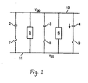
- decoupling capacitors 2, 3, 4 are coupled between two power rails 10, 11. These decoupling capacitors 2, 3, 4 protect the logic circuitry 5, 6 from transient voltage spikes and stabilize the supply voltage that is seen by the logic circuitry 5, 6.
- power rail 10 is V dd or V cc .
- power rail 11 is V ss or ground.
- Decoupling capacitors 2, 3, 4 may be a single capacitor; however, in the preferred embodiment they are an array of decoupling capacitors connected in parallel. Also in the preferred embodiment, the decoupling capacitors are made from a high-k dielectric film such as Ta 2 O 5 ; however, capacitors made from other materials such as gate oxide, metal plate capacitors, or metal flux capacitors are also within the scope of this invention.
- fuses 7, 8, 9 that are coupled between power rail 11 and decoupling capacitors 2, 3, and 4 respectively.
- fuses 7, 8, 9 are poly electrical fuses having a resistance of approximately 100 ⁇ .
- alternative fuses such as contact, via, or metal fuses.
- fuses having a different resistance for example a fuse having a nominal resistance anywhere from 10 ⁇ to 300 ⁇ .
- the resistance of the fuses 7, 8, 9 is kept to a minimal level in order to allow the non-defective decoupling capacitors to efficiently mitigate the effects of high frequency current glitches on the power rail 10.
- the non-defective decoupling capacitors When power is applied to the circuit on power rail 10 the non-defective decoupling capacitors will function in a manner that will support the logic circuitry 5, 6. However, if any decoupling capacitor has a shorting defect, for example in one or more of the capacitors in the capacitor array 4, then the defective decoupling capacitor may be very low resistance and act as a short that allows excessive current (i.e. up to tens of milliamps, depending on the supply voltage) to flow into the electrical fuse 9 connected to the capacitor array 4. This excessive current will overwhelm the fuse 9 and cause the fuse 9 to blow (i.e. become high resistance); thereby creating an open circuit and removing the defective decoupling capacitor array 4 from further operation.
- excessive current i.e. up to tens of milliamps, depending on the supply voltage
- the fuse 9 connected to the shorted decoupling capacitor 4 can be blown by raising the voltage level on power rail 10 to a level that opens the circuit (i.e. 1.5 to 2 times the normal operating voltage).
- the increased voltage only has to be present on power rail 10 for a short time (i.e. 2-3 ps); therefore the voltage on rail 10 can be raised safely to any level below the reliability imposed voltage limit in order to open a circuit containing a defective decoupling capacitor.
Landscapes
- Semiconductor Integrated Circuits (AREA)
- Train Traffic Observation, Control, And Security (AREA)
- Power Conversion In General (AREA)
- Fuses (AREA)
- Protection Of Static Devices (AREA)
Abstract
Description
Claims (16)
- A circuit comprising:at least one decoupling capacitor coupled between a first power rail and a second power rail; andat least one fuse coupled between said at least one decoupling capacitor and at least one said power rail.
- The circuit of Claim 1 wherein said decoupling capacitor is comprised of gate oxide.
- The circuit of Claim 1 or 2 wherein one of said power rails is Vdd and the other one of said power rails is ground.
- The circuit of any one of Claims 1 to 3 wherein said decoupling capacitor is comprised of high-k dielectric film.
- The circuit of Claim 1 wherein said fuse is a poly electrical fuse.
- A circuit comprising:two or more parallel decoupling capacitors coupled between a first power rail and a second power rail; andone fuse connected between said decoupling capacitors and said first power rail.
- The circuit of Claim 6 wherein said fuse is a poly electrical fuse.
- The circuit of Claim 6 or 7 wherein said fuse has a nominal resistance below approximately 200 ohms.
- The circuit of any one of Claims 6 to 8 wherein said decoupling capacitors are comprised of gate oxide.
- The circuit of any one of Claims 6 to 9 wherein said decoupling capacitors are comprised of high-k dielectric film.
- The circuit of any one of Claims 6 to 10 wherein said first power rail is ground.
- The circuit of any one of Claims 6 to 11 wherein said second power rail is Vdd.
- A method for eliminating defective capacitors comprising:applying power to a circuit wherein a fuse connected to a shortened decoupling capacitor blows open.
- The method of claim 13 wherein said fuse is blown by current flowing from a power rail, through said shortened decoupling capacitor, and then into said fuse.
- The method of claim 13 or 14 wherein the level of said power is approximately Vdd.
- The method of claim 13 or 14 wherein the level is said power is between Vdd and the maximum reliability imposed voltage limits of said circuit.
Applications Claiming Priority (2)
| Application Number | Priority Date | Filing Date | Title |
|---|---|---|---|
| US10/287,403 US20040085120A1 (en) | 2002-11-04 | 2002-11-04 | Eliminating defective decoupling capacitors |
| US287403 | 2002-11-04 |
Publications (2)
| Publication Number | Publication Date |
|---|---|
| EP1416536A2 true EP1416536A2 (en) | 2004-05-06 |
| EP1416536A3 EP1416536A3 (en) | 2009-06-24 |
Family
ID=32093605
Family Applications (1)
| Application Number | Title | Priority Date | Filing Date |
|---|---|---|---|
| EP03104026A Withdrawn EP1416536A3 (en) | 2002-11-04 | 2003-10-30 | Eliminating defective decoupling capacitors |
Country Status (3)
| Country | Link |
|---|---|
| US (1) | US20040085120A1 (en) |
| EP (1) | EP1416536A3 (en) |
| JP (1) | JP2004159495A (en) |
Cited By (1)
| Publication number | Priority date | Publication date | Assignee | Title |
|---|---|---|---|---|
| EP1624597A3 (en) * | 2004-08-06 | 2006-03-01 | Robert Bosch Gmbh | Fuse in series with capacitor to avoid the consequences of a short circuit in the capacitor |
Families Citing this family (7)
| Publication number | Priority date | Publication date | Assignee | Title |
|---|---|---|---|---|
| FR2847715B1 (en) * | 2002-11-25 | 2005-03-11 | Commissariat Energie Atomique | INTEGRATED CIRCUIT COMPRISING SERIES CONNECTED SUBASSEMBLIES |
| GB0307306D0 (en) * | 2003-03-29 | 2003-05-07 | Goodrich Control Sys Ltd | Fuse arrangement |
| US7435627B2 (en) * | 2005-08-11 | 2008-10-14 | International Business Machines Corporation | Techniques for providing decoupling capacitance |
| US8294505B2 (en) * | 2005-08-23 | 2012-10-23 | International Business Machines Corporation | Stackable programmable passive device and a testing method |
| US8610188B2 (en) * | 2011-09-15 | 2013-12-17 | GlobalFoundries, Inc. | Integrated circuit decoupling capacitor arrangement |
| TWI521664B (en) * | 2013-09-03 | 2016-02-11 | 瑞昱半導體股份有限公司 | Metal trench decoupling capacitor structure and method for forming metal trench decoupling capacitor structure |
| US9385079B2 (en) * | 2014-01-29 | 2016-07-05 | Taiwan Semiconductor Manufacturing Company, Ltd. | Methods for forming stacked capacitors with fuse protection |
Family Cites Families (7)
| Publication number | Priority date | Publication date | Assignee | Title |
|---|---|---|---|---|
| JPH01105569A (en) * | 1987-10-19 | 1989-04-24 | Oki Electric Ind Co Ltd | Semiconductor integrated device and removing method for malfunction thereof |
| JPH0438862A (en) * | 1990-06-04 | 1992-02-10 | Nec Corp | Semiconductor integrated circuit device |
| US5394294A (en) * | 1992-12-17 | 1995-02-28 | International Business Machines Corporation | Self protective decoupling capacitor structure |
| US5896059A (en) * | 1997-05-09 | 1999-04-20 | International Business Machines Corporation | Decoupling capacitor fuse system |
| US6737728B1 (en) * | 2000-10-12 | 2004-05-18 | Intel Corporation | On-chip decoupling capacitor and method of making same |
| US6686791B2 (en) * | 2002-04-25 | 2004-02-03 | Intel Corporation | Oxide anti-fuse structure utilizing high voltage transistors |
| US6608365B1 (en) * | 2002-06-04 | 2003-08-19 | Lsi Logic Corporation | Low leakage PMOS on-chip decoupling capacitor cells compatible with standard CMOS cells |
-
2002
- 2002-11-04 US US10/287,403 patent/US20040085120A1/en not_active Abandoned
-
2003
- 2003-10-30 EP EP03104026A patent/EP1416536A3/en not_active Withdrawn
- 2003-10-31 JP JP2003371585A patent/JP2004159495A/en active Pending
Cited By (1)
| Publication number | Priority date | Publication date | Assignee | Title |
|---|---|---|---|---|
| EP1624597A3 (en) * | 2004-08-06 | 2006-03-01 | Robert Bosch Gmbh | Fuse in series with capacitor to avoid the consequences of a short circuit in the capacitor |
Also Published As
| Publication number | Publication date |
|---|---|
| EP1416536A3 (en) | 2009-06-24 |
| JP2004159495A (en) | 2004-06-03 |
| US20040085120A1 (en) | 2004-05-06 |
Similar Documents
| Publication | Publication Date | Title |
|---|---|---|
| US8785300B2 (en) | BEOL anti-fuse structures for gate last semiconductor devices | |
| US6795286B2 (en) | RC-timer circuit to reduce current leakage in future semiconductor processes | |
| USRE35828E (en) | Anti-fuse circuit and method wherein the read operation and programming operation are reversed | |
| US7889469B2 (en) | Electrostatic discharge protection circuit for protecting semiconductor device | |
| EP1142119B1 (en) | On-chip decoupling capacitor system with parallel fuse | |
| EP0898786A1 (en) | Method and apparatus for programming anti-fuses using internally generated programming voltage | |
| CN100508322C (en) | protection circuit for integrated circuit device | |
| US20090168282A1 (en) | Esd protection circuit | |
| US20040085120A1 (en) | Eliminating defective decoupling capacitors | |
| US20160218503A1 (en) | Electrostatic discharge protection solutions | |
| US6597234B2 (en) | Anti-fuse circuit and method of operation | |
| US6469884B1 (en) | Internal protection circuit and method for on chip programmable poly fuses | |
| US8755241B2 (en) | Method and apparatus for programming an anti-fuse element in a high-voltage integrated circuit | |
| US12489290B2 (en) | Electro-static discharge (ESD) protection circuit and electronic device including ESD protection circuit | |
| CN111445943B (en) | On-chip one-time programmable circuit | |
| JP2001308280A (en) | Structure of precision circuit element and method of forming the same | |
| US6456474B2 (en) | Semiconductor integrated circuit | |
| EP0371663A1 (en) | Integrated circuit output buffer having improved ESD protection | |
| US7511355B2 (en) | Semiconductor device having fuse element | |
| US6667865B2 (en) | Efficient design of substrate triggered ESD protection circuits | |
| US20100164604A1 (en) | Fuse circuit and layout designing method thereof | |
| US20060198069A1 (en) | Power ESD clamp protection circuit | |
| JP3025373B2 (en) | Semiconductor integrated circuit | |
| US6633468B1 (en) | High voltage protection circuit for improved oxide reliability | |
| KR100413893B1 (en) | Method for reading electric fuses/antifuses |
Legal Events
| Date | Code | Title | Description |
|---|---|---|---|
| PUAI | Public reference made under article 153(3) epc to a published international application that has entered the european phase |
Free format text: ORIGINAL CODE: 0009012 |
|
| AK | Designated contracting states |
Kind code of ref document: A2 Designated state(s): AT BE BG CH CY CZ DE DK EE ES FI FR GB GR HU IE IT LI LU MC NL PT RO SE SI SK TR |
|
| AX | Request for extension of the european patent |
Extension state: AL LT LV MK |
|
| PUAL | Search report despatched |
Free format text: ORIGINAL CODE: 0009013 |
|
| AK | Designated contracting states |
Kind code of ref document: A3 Designated state(s): AT BE BG CH CY CZ DE DK EE ES FI FR GB GR HU IE IT LI LU MC NL PT RO SE SI SK TR |
|
| AX | Request for extension of the european patent |
Extension state: AL LT LV MK |
|
| AKX | Designation fees paid | ||
| REG | Reference to a national code |
Ref country code: DE Ref legal event code: 8566 |
|
| STAA | Information on the status of an ep patent application or granted ep patent |
Free format text: STATUS: THE APPLICATION IS DEEMED TO BE WITHDRAWN |
|
| 18D | Application deemed to be withdrawn |
Effective date: 20091229 |