EP1416468A2 - Method of fast processing image data for improving image visibility - Google Patents
Method of fast processing image data for improving image visibility Download PDFInfo
- Publication number
- EP1416468A2 EP1416468A2 EP20030254131 EP03254131A EP1416468A2 EP 1416468 A2 EP1416468 A2 EP 1416468A2 EP 20030254131 EP20030254131 EP 20030254131 EP 03254131 A EP03254131 A EP 03254131A EP 1416468 A2 EP1416468 A2 EP 1416468A2
- Authority
- EP
- European Patent Office
- Prior art keywords
- image data
- pixel
- area
- virtual screen
- resolution
- Prior art date
- Legal status (The legal status is an assumption and is not a legal conclusion. Google has not performed a legal analysis and makes no representation as to the accuracy of the status listed.)
- Ceased
Links
Images








Classifications
-
- G—PHYSICS
- G09—EDUCATION; CRYPTOGRAPHY; DISPLAY; ADVERTISING; SEALS
- G09G—ARRANGEMENTS OR CIRCUITS FOR CONTROL OF INDICATING DEVICES USING STATIC MEANS TO PRESENT VARIABLE INFORMATION
- G09G3/00—Control arrangements or circuits, of interest only in connection with visual indicators other than cathode-ray tubes
- G09G3/20—Control arrangements or circuits, of interest only in connection with visual indicators other than cathode-ray tubes for presentation of an assembly of a number of characters, e.g. a page, by composing the assembly by combination of individual elements arranged in a matrix no fixed position being assigned to or needed to be assigned to the individual characters or partial characters
-
- G—PHYSICS
- G09—EDUCATION; CRYPTOGRAPHY; DISPLAY; ADVERTISING; SEALS
- G09G—ARRANGEMENTS OR CIRCUITS FOR CONTROL OF INDICATING DEVICES USING STATIC MEANS TO PRESENT VARIABLE INFORMATION
- G09G5/00—Control arrangements or circuits for visual indicators common to cathode-ray tube indicators and other visual indicators
- G09G5/02—Control arrangements or circuits for visual indicators common to cathode-ray tube indicators and other visual indicators characterised by the way in which colour is displayed
- G09G5/04—Control arrangements or circuits for visual indicators common to cathode-ray tube indicators and other visual indicators characterised by the way in which colour is displayed using circuits for interfacing with colour displays
-
- G—PHYSICS
- G09—EDUCATION; CRYPTOGRAPHY; DISPLAY; ADVERTISING; SEALS
- G09G—ARRANGEMENTS OR CIRCUITS FOR CONTROL OF INDICATING DEVICES USING STATIC MEANS TO PRESENT VARIABLE INFORMATION
- G09G3/00—Control arrangements or circuits, of interest only in connection with visual indicators other than cathode-ray tubes
- G09G3/20—Control arrangements or circuits, of interest only in connection with visual indicators other than cathode-ray tubes for presentation of an assembly of a number of characters, e.g. a page, by composing the assembly by combination of individual elements arranged in a matrix no fixed position being assigned to or needed to be assigned to the individual characters or partial characters
- G09G3/22—Control arrangements or circuits, of interest only in connection with visual indicators other than cathode-ray tubes for presentation of an assembly of a number of characters, e.g. a page, by composing the assembly by combination of individual elements arranged in a matrix no fixed position being assigned to or needed to be assigned to the individual characters or partial characters using controlled light sources
-
- G—PHYSICS
- G09—EDUCATION; CRYPTOGRAPHY; DISPLAY; ADVERTISING; SEALS
- G09G—ARRANGEMENTS OR CIRCUITS FOR CONTROL OF INDICATING DEVICES USING STATIC MEANS TO PRESENT VARIABLE INFORMATION
- G09G2320/00—Control of display operating conditions
- G09G2320/06—Adjustment of display parameters
- G09G2320/0666—Adjustment of display parameters for control of colour parameters, e.g. colour temperature
-
- G—PHYSICS
- G09—EDUCATION; CRYPTOGRAPHY; DISPLAY; ADVERTISING; SEALS
- G09G—ARRANGEMENTS OR CIRCUITS FOR CONTROL OF INDICATING DEVICES USING STATIC MEANS TO PRESENT VARIABLE INFORMATION
- G09G2340/00—Aspects of display data processing
- G09G2340/04—Changes in size, position or resolution of an image
- G09G2340/0407—Resolution change, inclusive of the use of different resolutions for different screen areas
-
- G—PHYSICS
- G09—EDUCATION; CRYPTOGRAPHY; DISPLAY; ADVERTISING; SEALS
- G09G—ARRANGEMENTS OR CIRCUITS FOR CONTROL OF INDICATING DEVICES USING STATIC MEANS TO PRESENT VARIABLE INFORMATION
- G09G3/00—Control arrangements or circuits, of interest only in connection with visual indicators other than cathode-ray tubes
- G09G3/20—Control arrangements or circuits, of interest only in connection with visual indicators other than cathode-ray tubes for presentation of an assembly of a number of characters, e.g. a page, by composing the assembly by combination of individual elements arranged in a matrix no fixed position being assigned to or needed to be assigned to the individual characters or partial characters
- G09G3/2007—Display of intermediate tones
- G09G3/2074—Display of intermediate tones using sub-pixels
-
- G—PHYSICS
- G09—EDUCATION; CRYPTOGRAPHY; DISPLAY; ADVERTISING; SEALS
- G09G—ARRANGEMENTS OR CIRCUITS FOR CONTROL OF INDICATING DEVICES USING STATIC MEANS TO PRESENT VARIABLE INFORMATION
- G09G3/00—Control arrangements or circuits, of interest only in connection with visual indicators other than cathode-ray tubes
- G09G3/20—Control arrangements or circuits, of interest only in connection with visual indicators other than cathode-ray tubes for presentation of an assembly of a number of characters, e.g. a page, by composing the assembly by combination of individual elements arranged in a matrix no fixed position being assigned to or needed to be assigned to the individual characters or partial characters
- G09G3/22—Control arrangements or circuits, of interest only in connection with visual indicators other than cathode-ray tubes for presentation of an assembly of a number of characters, e.g. a page, by composing the assembly by combination of individual elements arranged in a matrix no fixed position being assigned to or needed to be assigned to the individual characters or partial characters using controlled light sources
- G09G3/28—Control arrangements or circuits, of interest only in connection with visual indicators other than cathode-ray tubes for presentation of an assembly of a number of characters, e.g. a page, by composing the assembly by combination of individual elements arranged in a matrix no fixed position being assigned to or needed to be assigned to the individual characters or partial characters using controlled light sources using luminous gas-discharge panels, e.g. plasma panels
Definitions
- the present invention relates to a method of processing image data, and more particularly, to a method of processing input image data to generate output image data for driving a display panel.
- a general method of processing image data includes a first virtual screen, which is divided into a plurality of pixel areas according to the resolution of input image data, and a second virtual screen having a sub-pixel array of a display panel.
- the second virtual screen includes red sub-pixel areas, green sub-pixel areas, and blue sub-pixel areas.
- Input image data has only position information of a unit pixel but does not have position information of sub-pixels, i.e. , a red sub-pixel, a green sub-pixel, and a blue sub-pixel, constituting the unit pixel.
- the positions of sub-pixels are different in different pixel areas in any display panel.
- a distance between red sub-pixels, a distance between green sub-pixels, and a distance between blue sub-pixels are different from one another. Accordingly, visibility of images displayed on display panels is degraded.
- a method of processing image data to generate output image data for driving a display panel In the method, a new resolution for input image data is set according to a resolution of the display panel. A first virtual screen is divided into a plurality of pixel areas according to the new resolution set for the input image data. A second virtual screen having a sub-pixel array structure of the display panel is superimposed on the first virtual screen. A mask wider than a sub-pixel area on the superimposed second virtual screen is laid on each sub-pixel area. An area ratio of the area of each pixel portion on the first virtual screen included in each mask to the area of the mask is obtained and set.
- the new resolution and the area ratios are applied to a driving device of the display panel.
- the input image data having an original resolution is transformed into image data having the new and enhanced resolution.
- the sum of the results of multiplying an area ratio of the area of each pixel portion on the first virtual screen included in each mask by the transformed image data of the pixel areas, respectively, is generated as output image data of a sub-pixel corresponding to the mask.
- the present invention thus provides a method of processing image data which aims to fundamentally solve the problem of image visibility due to the sub-pixel array structure of a display panel with the minimum number of input image data transforming operations.
- Image data is processed by providing a new resolution for input image data that is set in order to maximize the number of masks having the same area ratio structures and accordingly, the number of masks to be used is minimized, so the number of times area ratios are multiplied by transformed image data is minimized, thereby increasing display speed and decreasing necessary memory-capacity.
- the invention also may correct a color error, which may occur during data processing.
- the method of processing image data according to the present invention has the following effects.
- a new resolution for input image data can be set in order to maximize the number of masks having the same area ratio structures. Accordingly, the number of masks to be used is minimized, so the number of times area ratios are multiplied by transformed image data is minimized, thereby increasing display speed and decreasing necessary memory-capacity.
- each sub-pixel of a display panel is involved with the data of its adjacent pixels on a first virtual screen, so a problem in reproducing an image due to the sub-pixel array structure of the display panel can be radically solved.
- FIG. 1 shows the principle of a general method of processing image data.
- a reference character V SS denotes a first virtual screen, which is divided into a plurality of pixel areas according to the resolution of input image data.
- a reference character V DS denotes a second virtual screen having a sub-pixel array of a display panel. On the second virtual screen V DS , areas having a circle at their center are red sub-pixel areas, areas having a square at their center are green sub-pixel areas, and areas having a diamond at their center are blue sub-pixel areas.
- input image data has only position information of a unit pixel but does not have position information of sub-pixels, i.e. , a red sub-pixel, a green sub-pixel, and a blue sub-pixel, constituting the unit pixel.
- the positions of sub-pixels are different in different pixel areas in any display panel.
- a distance between red sub-pixels, a distance between green sub-pixels, and a distance between blue sub-pixels are different from one another. Accordingly, visibility of images displayed on display panels is degraded.
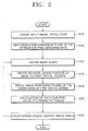
- sub-pixel rendering methodology includes checking input signal resolution (step A10). After checking the input signal resolution, the input resolution conversion is made to one of the optimum sub-pixel rendering ratios (step A12). After step A 12, the mask shape is decided (step A 14). The relative laying position of the mask to the first virtual screen is also decided (step A16). Tables proportionate to the area of the divided mask by the first virtual screen are obtained (step A18). The sub pixel values are calculated according to the tables (step A20). Finally, the color checked for any errors and the output image is checked (step A22).
- FIG. 3 shows the principle of a method of processing image data according to the present invention.
- a reference character V SS denotes a first virtual screen, which is divided into a plurality of pixel areas according to a new resolution of input image data.
- a reference character V DS denotes a second virtual screen having a sub-pixel array of a display panel. On the second virtual screen V DS , areas having a circle at their center are red sub-pixel areas, areas having a square at their center are green sub-pixel areas, and areas having a diamond at their center are blue sub-pixel areas.
- FIG. 4 shows a method of processing image data according to an embodiment of the present invention.
- steps S 1 through S5 indicate steps of setting a resolution and an area ratio during manufacture of a display driving device.
- the method of processing image data according to an embodiment of the present invention will be schematically described with reference to FIGS. 3 and 4.
- a new resolution for input image data is set according to the resolution of a display panel in step S1.
- a new horizontal resolution and a new vertical resolution are set.
- the new horizontal resolution for the input image data is set according to the horizontal resolution of the display panel
- the new vertical resolution for the input image data is set according to the vertical resolution of the display panel.
- the first virtual screen V SS is divided into a plurality of pixel areas according to the new resolution of the input image data in step S2.
- the second virtual screen V DS having the sub-pixel array structure of a display panel is superimposed on the first virtual screen V SS in step S3.
- a mask which is wider than each sub-pixel area of the display panel on the superimposition of the virtual screens V DS -V SS , is laid on each cell area of the display panel in step S4. It is also preferable that the mask does not include the next same color sub-pixel. For example, if the mask includes a first color sub-pixel, then the mask should not touch or include the next sub-pixel having also the first color. As another example, the mask may include only one of each sub-pixel color.
- step S6 An area ratio table showing the ratio of the area of each pixel portion of the first virtual screen V SS in each mask to the area of the mask, is obtained and set in step S5.
- step S6 the resolution set in step S1 and the area ratio table set in step S5 are applied to a driving device of the display panel, the input image data is transformed so that the original resolution of the input image data is changed into the new resolution set in step S1, and then the sum of the results of multiplying the ratio of the area of each pixel portion included in each mask to the area of the mask by the transformed image data is generated as output image data of a sub-pixel corresponding to the mask.
- each sub-pixel of the display panel is involved with the data of its adjacent pixels on the first virtual screen V SS . Accordingly, as shown in FIG. 3, the input image data of the first virtual screen V SS can be corrected to be suitable to the sub-pixel array structure of the display panel, thereby radically solving a problem in image visibility due to the sub-pixel array structure of the display panel.
- step S1 the new resolution for the input image data is set to maximize the number of masks having the same area ratio structures in step S5, so the number of masks used in step S4 is minimized. Consequently, the number of times the area ratios are multiplied by the transformed image data is minimized.
- step S2 shown in FIG. 4 when step S2 shown in FIG. 4 is performed, the first virtual screen V SS is divided into a plurality of pixel areas VP 11 through VP 6(10) according to the new resolution set for the input image data.
- FIG. 6 shows an example of the superimposition of the virtual screens V DS -V SS resulting from step S3 shown in FIG. 4 when a ratio of the new resolution of the input image data to the resolution of the display panel is 1:1.
- reference characters CR 12 through CR 33 denote red sub-pixel areas
- reference characters CG 11 through CG 33 denote green sub-pixel areas
- reference characters CB 11 through CB 33 denote blue sub-pixel areas.
- the second virtual screen V DS having a delta structure as the sub-pixel array structure of the display panel is superimposed on the first virtual screen V SS .
- the second virtual screen V DS divided into plurality of sub-pixel areas CG 11 through CR 33 is superimposed on the first virtual screen V SS divided into a plurality of pixel areas VP 15 through VP 47 .
- FIG. 7 shows an example of the superimposition of the virtual screens V DS -V SS resulting from step S3 shown in FIG. 4 when a ratio of the new resolution of the input image data to the resolution of the display panel is 1.5:1.
- areas defined by solid lines are pixel areas on the first virtual screen V SS
- areas defined by dotted lines are sub-pixel areas on the second virtual screen V DS .
- areas having a circle at their center are red sub-pixel areas
- areas having a square at their center are green sub-pixel areas
- areas having a diamond at their center are blue sub-pixel areas.
- FIG. 8A shows an example of the superimposition of the virtual screens V DS -V SS on which a quadrilateral mask is laid on each blue sub-pixel area as the result of performing step S4 shown in FIG. 4 when a ratio of the new resolution of the input image data to the resolution of the display panel is 1.5:1.
- step S5 shown in FIG. 4 is performed.
- FIG.8B shows an enlarged view of a hatched mask M nm shown in FIG. 8A in order to explain an algorithm used in step S5 shown in FIG. 4.
- the mask M nm is for a blue sub-pixel at an n-th place in a horizontal direction and an m-th place in a vertical direction.
- a reference character A LU denotes the area of an upper left pixel portion
- a reference character A RU denotes the area of an upper right pixel portion
- a reference character ALL denotes the area of a lower left pixel portion
- a reference character A RL denotes the area of a lower right pixel portion.
- an area ratio of the area of each pixel portion of the first virtual screen V SS included in the blue sub-pixel mask M nm to the area of the blue sub-pixel mask M nm is obtained using the areas A LU , A RU , A LL , and A RL and a unit mask area A LU + A RU + A LL + A RL .
- output image data b mn for the blue sub-pixel shown in FIG. 8B is obtained using Formula (1).
- b mn A LU ⁇ b LU + A RU ⁇ b RU + A LL ⁇ b LL + A RL ⁇ b RL / A LU + A RU + A LL + A RL
- b LU indicates blue image data of a pixel area including the area A LU on the first virtual screen V SS
- b RU indicates blue image data of a pixel area including the area A RU on the first virtual screen V SS
- b LL indicates blue image data of a pixel area including the area A LL on the first virtual screen V SS
- b RL indicates blue image data of a pixel area including the area A RL on the first virtual screen V SS .
- the input image data of the first virtual screen V SS can be corrected to be suitable to the sub-pixel array structure of the display panel, thereby radically solving a problem in image visibility due to the sub-pixel array structure of the display panel.
- FIG. 9A shows an example of the superimposition of the virtual screens V DS -V SS on which a hexagonal mask is laid on each blue sub-pixel area as the result of performing step S4 shown in FIG. 4 when a ratio of the new resolution of the input image data to the resolution of the display panel is 1.5:1.
- step S5 shown in FIG. 4 is performed.
- FIG. 9B shows an enlarged view of a hatched mask M nm shown in FIG. 9A in order to explain another algorithm used in step S5 shown in FIG. 4.
- the mask M nm is for a blue sub-pixel at an n-th place in a horizontal direction and an m-th place in a vertical direction.
- a reference character A 1 denotes the area of a first pixel portion
- a reference character A 2 denotes the area of a second pixel portion
- a reference character A 3 denotes the area of a third pixel portion
- a reference character A 4 denotes the area of a fourth pixel portion
- a reference character A 5 denotes the area of a fifth pixel portion
- a reference character A 6 denotes the area of a sixth pixel portion.
- an area ratio of the area of each pixel portion of the first virtual screen V SS included in the blue sub-pixel mask M nm to the area of the blue sub-pixel mask M nm is obtained using the areas A 1 , A 2 , A 3 , A 4 , A 5 , and A 6 and a unit mask area A 1 + A 2 + A 3 + A 4 + A 5 + A 6 .
- output image data b mn for the blue sub-pixel shown in FIG. 9B is obtained using Formula (2).
- b mn A 1 ⁇ b 1 + A 2 ⁇ b 2 + A 3 ⁇ b 3 + A 4 ⁇ b 4 + A 5 ⁇ b 5 + A 6 ⁇ b 6 / A 1 + A 2 + A 3 + A 4 + A 5 + A 6
- b 1 indicates blue image data of a pixel area including the area A 1 on the first virtual screen V SS
- b 2 indicates blue image data of a pixel area including the area A 2 on the first virtual screen V SS
- b 3 indicates blue image data of a pixel area including the area A 3 on the first virtual screen V SS
- b 4 indicates blue image data of a pixel area including the area A 4 on the first virtual screen V SS
- b 5 indicates blue image data of a pixel area including the area A 5 on the first virtual screen V SS
- b 6 indicates blue image data of a pixel area including the area A 6 on the first virtual screen V SS .
- the input image data of the first virtual screen V SS can be corrected to be suitable to the sub-pixel array structure of the display panel, thereby radically solving a problem in image visibility due to the sub-pixel array structure of the display panel.
- formula 2 can be shown with the output image data b mn for the blue sub-pixel shown in FIG. 9B being obtained using Formula (3).
- A indicates an area of a portion of the mask
- z is the number of portions of the mask
- b is the image data of a pixel area including the area A on the first virtual screen. Therefore, y is an integer from 1 to the total number of portions z of the mask.
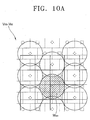
- FIG. 10A shows an example of the superimposition of the virtual screens V DS -V SS on which a circular mask is laid on each blue sub-pixel area as the result of performing step S4 shown in FIG. 4 when a ratio of the new resolution of the input image data to the resolution of the display panel is 1.5:1.
- FIG. 10B shows an enlarged view of a hatched mask M nm shown in FIG. 10A in order to explain an algorithm used in step S5 shown in FIG. 4.
- the mask M nm is for a blue sub-pixel at an n-th place in a horizontal direction and an m-th place in a vertical direction.
- a reference character A LU denotes the area of an upper left pixel portion
- a reference character A RU denotes the area of an upper right pixel portion
- a reference character A LL denotes the area of a lower left pixel portion
- a reference character A RL denotes the area of a lower right pixel portion.
- FIGS. 10A and 10B The description of FIGS. 10A and 10B is the same as that of FIGS. 8A and 8B, and is thus omitted.
- circular masks are ideal in theory, but in practice some pixel areas are used twice and some pixel areas are not used at all in obtaining output image data. Accordingly, circular masks are less preferable than quadrilateral and hexagonal masks.
- the shape of masks is the same as the shape of sub-pixels of a display panel.
- FIG. 11 shows sub-pixel areas on the second virtual screen V DS , which are disposed at different horizontal and vertical positions with respect to unit pixel areas on the first virtual screen V SS when a ratio of the new resolution of the input image data to the resolution of the display panel is 1.4:1.
- areas defined by solid lines are pixel areas on the first virtual screen V SS
- areas defined by dotted lines are sub-pixel areas on the second virtual screen V DS .
- areas having a circle at their center are red sub-pixel areas
- areas having a square at their center are green sub-pixel areas
- areas having a diamond at their center are blue sub-pixel areas.
- step S6 the number of times , that area ratios are multiplied by transformed image data, relatively increases, thereby decreasing display speed and increasing necessary memory-capacity.
- FIG. 12 shows sub-pixel areas on the second virtual screen V DS , which are disposed at different horizontal and vertical positions with respect to unit pixel areas on the first virtual screen V SS when a ratio of the new resolution of the input image data to the resolution of the display panel is 1.5:1.
- areas defined by solid lines are pixel areas on the first virtual screen V SS .
- areas having a circle at their center are red sub-pixel areas, areas having a square at their center are green sub-pixel areas, and areas having a diamond at their center are blue sub-pixel areas.
- the number of different horizontal positions of sub-pixel areas is 0, and the number of different vertical positions thereof is 4.
- step S6 the number of times area ratios are multiplied by transformed image data decreases, thereby increasing display speed.
- an area ratio table shown in Table 1 is obtained in step S5 shown in FIG. 4.
- Pixel-area positions Sums 1 2 3 4 5 6 7 Masks A 2 1 16 8 6 3 36 B 10 5 14 7 36 C 7 14 5 10 36 D 3 6 8 16 1 2 36
- the mask shown in FIG. 8B corresponds to the mask C in Table 1.
- the area A LL has area ratio of 7
- the area A RL has area ratio of 14
- the area A LU has area ratio of 5
- the area A RU has area ratio of 10.
- FIG. 13A is a graph of the number of different horizontal positions with respect to a horizontal resolution ratio when the sub-pixel areas of a display panel have a delta structure.
- the delta structure is a sub-pixel array structure shown in the second virtual screen V DS of FIG. 3.
- FIG. 13B is a graph of the number of different vertical positions with respect to a vertical resolution ratio when the sub-pixel areas of a display panel have a delta structure. Referring to FIG. 13B, it is preferable to set a new vertical resolution for input image data such that a ratio of the new vertical resolution to the vertical resolution of the display panel is 1:1, 1.2:1, 1.5:1, 1.6:1, or 2:1.
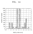
- FIG. 14 is a graph of the number of masks with respect to a resolution ratio when the sub-pixel areas of a display panel have a striped structure.
- a resolution ratio means a vertical resolution ratio and a horizontal resolution ratio which are the same.
- red sub-pixel areas are positioned on a first line
- green sub-pixel areas are positioned on a second line
- blue sub-pixel areas are positioned on a third line.
- Tables 2A through 2C The detailed data of the graph shown in FIG. 14 is shown in Tables 2A through 2C.
- a delta type structure of the sub-pixel areas of a display panel is more preferable than a striped structure because in a stripe type structure, the sub-pixels that are located on the up and down side of a certain sub-pixel are of the same color so that the first imaginary image cells which are vertically located of a certain sub-pixel and overlapped by a mask are less effective to the sub-pixel in the process of sub-pixel rendering than delta type structure.
- FIG. 15 is a graph of the number of masks with respect to a resolution ratio when the sub-pixel areas of a display panel have a delta structure.
- a resolution ratio means a vertical resolution ratio and a horizontal resolution ratio which are the same.
- the detailed data of the graph shown in FIG. 15 is shown in Tables 3A through 3C.
- Number of masks 6 300 25
- 300 150 resolution ratio 1.6:1 1.7:1 1.8:1 1.9:1 2.0:1 2.1:1 Number of masks 75 Over 2000 25 Over 2000 3 100 resolution ratio 2.2:1 2.3:1 2.4:1 2.5:1 2.6:1 ------
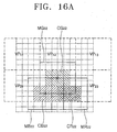
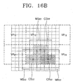
- FIG. 16A shows a state in which the central line of a pixel area on a first virtual screen is the central line of a sub-pixel area on a second virtual screen.
- FIG. 16B shows a state in which the central line of a pixel area on a first virtual screen is not the central line of a sub-pixel area on a second virtual screen.
- reference characters VP 11 through VP 23 denote some pixel areas on the first virtual screen.
- a reference character CR 22 denotes a red sub-pixel area on the second virtual screen
- a reference character CG 22 denotes a green sub-pixel area on the second virtual screen
- a reference character CB 22 denotes a blue sub-pixel area on the second virtual screen.
- a reference character MR 22 denotes a mask for the red sub-pixel area CR 22
- a reference character MG 22 denotes a mask for the green sub-pixel area CG 22
- a reference character MB 22 denotes a mask for the blue sub-pixel area CB 22 .
- the central vertical line of a pixel area on the first virtual screen is the central vertical line of the green sub-pixel area CG 22 on the second virtual screen.
- a mixture of red and blue i.e., a shade of magenta
- a shade of magenta may be visually conspicuous.
- the present invention is applicable to all types of display devices including for example plasma display panels (PDP), liquid crystal display (LCD) panels and ferroelectric liquid crystal (FLC) panels.
- PDP plasma display panels
- LCD liquid crystal display
- FLC ferroelectric liquid crystal
- a device for processing image data to generate output image data for driving a display panel can include the display panel such as a plasma display panel 100 connected to a display controller 102 and a display memory 104.
- the processor or controller 106 processes the image data stored in the image memory 108 and transfers the processed image data to the display memory 104 where the transferred data is managed by the display controller 102 for display on the display panel 100.
- FIG. 18 shows another view of a device for processing image data to generate output image data for driving a display panel according to the present invention.
- the display panel 100 is controlled by controller 112 using memory or computer readable media 114 ( e.g. non volatile read-only memory, random access memory, floppy disks, compact discs, digital versatile discs, hard disk drives, flash read-only memories, other optical and magnetic mediums, etc. ).
- memory or computer readable media 114 e.g. non volatile read-only memory, random access memory, floppy disks, compact discs, digital versatile discs, hard disk drives, flash read-only memories, other optical and magnetic mediums, etc.
- FIG. 19 another example of a device implementing the present invention is a display device unit 150 connected to a computer unit 200 and the computer unit 200 is connected to a remote computer 300.
- the display panel 100 such as a plasma display panel is driven by a display driving unit 120 and is connected to the computer unit 200 through the interface 130 of the display unit 150 and display interface 210 of the computer unit 200.
- the display interface 210 is connected to computer readable media such as the system memory 220 (read-only memory, random access memory) and storage media 240 (floppy disks, compact discs, digital versatile discs, hard disk drives, flash read-only memories, other optical and magnetic mediums, etc .).
- the system bus also connects the computer processor 230 with the computer readable medium and includes inputs through input device 262 and other input and output devices 260.
- the computer unit 200 can also be connected to a remote computer 300 through a network interface 250 and a network 400 such as the Internet.
- a method of processing image data according to the present invention has the following effects.
- a new resolution for input image data can be set in order to maximize the number of masks having the same area ratio structures. Accordingly, the number of masks to be used is minimized, so the number of times area ratios are multiplied by transformed image data is minimized, thereby increasing display speed and decreasing necessary memory-capacity.
- each sub-pixel of a display panel is involved with the data of its adjacent pixels on a first virtual screen, so a problem in reproducing an image due to the sub-pixel array structure of the display panel can be radically solved.
- a color error which may occur during data processing, can be corrected.
Landscapes
- Engineering & Computer Science (AREA)
- Physics & Mathematics (AREA)
- Computer Hardware Design (AREA)
- General Physics & Mathematics (AREA)
- Theoretical Computer Science (AREA)
- Control Of Indicators Other Than Cathode Ray Tubes (AREA)
- Controls And Circuits For Display Device (AREA)
- Transforming Electric Information Into Light Information (AREA)
- Video Image Reproduction Devices For Color Tv Systems (AREA)
- Television Systems (AREA)
Abstract
Description
- The present invention relates to a method of processing image data, and more particularly, to a method of processing input image data to generate output image data for driving a display panel.
- A general method of processing image data includes a first virtual screen, which is divided into a plurality of pixel areas according to the resolution of input image data, and a second virtual screen having a sub-pixel array of a display panel. The second virtual screen includes red sub-pixel areas, green sub-pixel areas, and blue sub-pixel areas.
- Input image data has only position information of a unit pixel but does not have position information of sub-pixels, i.e., a red sub-pixel, a green sub-pixel, and a blue sub-pixel, constituting the unit pixel. However, the positions of sub-pixels are different in different pixel areas in any display panel. Moreover, for two adjacent pixels, a distance between red sub-pixels, a distance between green sub-pixels, and a distance between blue sub-pixels are different from one another. Accordingly, visibility of images displayed on display panels is degraded.
- A technique related to the visibility of an image is disclosed in U.S. Patent No. 5,341,153 for Method and Apparatus for Displaying a Multicolor Image by Benzschawel et al. According to this technique, input image data having a high resolution is directly superimposed on a display panel having a low resolution. This technique cannot radically solve the image visibility problem of a display panel due to a sub-pixel array structure. Moreover, since an input image data transforming operation is individually performed for all of the sub-pixels of a display panel, display speed decreases.
- In order to accomplish the above and other objects, according to an aspect of the present invention, there is provided a method of processing image data to generate output image data for driving a display panel. In the method, a new resolution for input image data is set according to a resolution of the display panel. A first virtual screen is divided into a plurality of pixel areas according to the new resolution set for the input image data. A second virtual screen having a sub-pixel array structure of the display panel is superimposed on the first virtual screen. A mask wider than a sub-pixel area on the superimposed second virtual screen is laid on each sub-pixel area. An area ratio of the area of each pixel portion on the first virtual screen included in each mask to the area of the mask is obtained and set. The new resolution and the area ratios are applied to a driving device of the display panel. The input image data having an original resolution is transformed into image data having the new and enhanced resolution. The sum of the results of multiplying an area ratio of the area of each pixel portion on the first virtual screen included in each mask by the transformed image data of the pixel areas, respectively, is generated as output image data of a sub-pixel corresponding to the mask.
- The present invention thus provides a method of processing image data which aims to fundamentally solve the problem of image visibility due to the sub-pixel array structure of a display panel with the minimum number of input image data transforming operations.
- Image data is processed by providing a new resolution for input image data that is set in order to maximize the number of masks having the same area ratio structures and accordingly, the number of masks to be used is minimized, so the number of times area ratios are multiplied by transformed image data is minimized, thereby increasing display speed and decreasing necessary memory-capacity.
- By processing image data by having each sub-pixel of a display panel involved with the data of its adjacent pixels on a first virtual screen, so a problem in reproducing an image due to the sub-pixel array structure of the display panel can be radically solved.
- The invention also may correct a color error, which may occur during data processing.
- The method of processing image data according to the present invention has the following effects.
- First, a new resolution for input image data can be set in order to maximize the number of masks having the same area ratio structures. Accordingly, the number of masks to be used is minimized, so the number of times area ratios are multiplied by transformed image data is minimized, thereby increasing display speed and decreasing necessary memory-capacity.
- Second, each sub-pixel of a display panel is involved with the data of its adjacent pixels on a first virtual screen, so a problem in reproducing an image due to the sub-pixel array structure of the display panel can be radically solved.
- A more complete appreciation of the invention, and many of the attendant advantages thereof, will be readily apparent as the same becomes better understood by reference to the following detailed description when considered in conjunction with the accompanying drawings in which like reference symbols indicate the same or similar components, wherein:
- FIG. 1 shows the principle of a conventional method of processing image data;
- FIG. 2 is a diagram for sub-pixel rendering methodology;
- FIG. 3 shows the principle of a method of processing image data according to the present invention;
- FIG. 4 is a flowchart of a method of processing image data according to an embodiment of the present invention;
- FIG. 5 shows an example of a first virtual screen resulting from step S2 shown in FIG. 4;
- FIG. 6 shows an example of the superimposition of virtual screens resulting from step S3 shown in FIG. 4 when a ratio of a new resolution of input image data to the resolution of a display panel is 1:1;
- FIG. 7 shows an example of the superimposition of virtual screens resulting from step S3 shown in FIG. 4 when a ratio of a new resolution of input image data to the resolution of a display panel is 1.5:1;
- FIG. 8A shows an example of the superimposition of virtual screens on which a quadrilateral mask is laid on each blue sub-pixel area as the result of performing step S4 shown in FIG. 4 when a ratio of a new resolution of input image data to the resolution of a display panel is 1.5:1;
- FIG. 8B shows an enlarged view of a hatched mask area shown in FIG. 8A in order to explain an algorithm used in step S5 shown in FIG. 4;
- FIG. 9A shows an example of the superimposition of virtual screens on which a hexagonal mask is laid on each blue sub-pixel area as the result of performing step S4 shown in FIG. 4 when a ratio of a new resolution of input image data to the resolution of a display panel is 1.5:1;
- FIG. 9B shows an enlarged view of a hatched mask area shown in FIG. 9A in order to explain another algorithm used in step S5 shown in FIG. 4;
- FIG. 10A shows an example of the superimposition of virtual screens on which a circular mask is laid on each blue sub-pixel area as the result of performing step S4 shown in FIG. 4 when a ratio of a new resolution of input image data to the resolution of a display panel is 1.5:1;
- FIG. 10B shows an enlarged view of a hatched mask area shown in FIG. 10A in order to explain still another algorithm used in step S5 shown in FIG. 4;
- FIG. 11 shows sub-pixel areas on a second virtual screen, which are disposed at different horizontal and vertical positions with respect to unit pixel areas on a first virtual screen when a ratio of a new resolution of input image data to the resolution of a display panel is 1.4:1;
- FIG. 12 shows sub-pixel areas on a second virtual screen, which are disposed at different horizontal and vertical positions in different unit pixel areas on a first virtual screen when a ratio of a new resolution of input image data to the resolution of a display panel is 1.5:1;
- FIG. 13A is a graph of the number of different horizontal positions with respect to a horizontal resolution ratio when the sub-pixel areas of a display panel have a delta structure;
- FIG. 13B is a graph of the number of different vertical positions with respect to a vertical resolution ratio when the sub-pixel areas of a display panel have a delta structure;
- FIG. 14 is a graph of the number of masks with respect to a resolution ratio when the sub-pixel areas of a display panel have a striped structure;
- FIG. 15 is a graph of the number of masks with respect to a resolution ratio when the sub-pixel areas of a display panel have a delta structure;
- FIG. 16A shows a state in which the central line of a pixel area on a first virtual screen is the central line of a sub-pixel area on a second virtual screen;
- FIG. 16B shows a state in which the central line of a pixel area on a first virtual screen is not the central line of a sub-pixel area on a second virtual screen; and
- FIG. 17 through 19 show examples of devices including displays using the techniques of the present invention.
-
- FIG. 1 shows the principle of a general method of processing image data. A reference character VSS denotes a first virtual screen, which is divided into a plurality of pixel areas according to the resolution of input image data. A reference character VDS denotes a second virtual screen having a sub-pixel array of a display panel. On the second virtual screen VDS, areas having a circle at their center are red sub-pixel areas, areas having a square at their center are green sub-pixel areas, and areas having a diamond at their center are blue sub-pixel areas.
- Referring to FIG. 1, input image data has only position information of a unit pixel but does not have position information of sub-pixels, i.e., a red sub-pixel, a green sub-pixel, and a blue sub-pixel, constituting the unit pixel. However, the positions of sub-pixels are different in different pixel areas in any display panel. Moreover, for two adjacent pixels, a distance between red sub-pixels, a distance between green sub-pixels, and a distance between blue sub-pixels are different from one another. Accordingly, visibility of images displayed on display panels is degraded.
- Referring to the diagram of FIG. 2, sub-pixel rendering methodology includes checking input signal resolution (step A10). After checking the input signal resolution, the input resolution conversion is made to one of the optimum sub-pixel rendering ratios (step A12). After step A 12, the mask shape is decided (step A 14). The relative laying position of the mask to the first virtual screen is also decided (step A16). Tables proportionate to the area of the divided mask by the first virtual screen are obtained (step A18). The sub pixel values are calculated according to the tables (step A20). Finally, the color checked for any errors and the output image is checked (step A22).
- FIG. 3 shows the principle of a method of processing image data according to the present invention. A reference character VSS denotes a first virtual screen, which is divided into a plurality of pixel areas according to a new resolution of input image data. A reference character VDS denotes a second virtual screen having a sub-pixel array of a display panel. On the second virtual screen VDS, areas having a circle at their center are red sub-pixel areas, areas having a square at their center are green sub-pixel areas, and areas having a diamond at their center are blue sub-pixel areas.
- FIG. 4 shows a method of processing image data according to an embodiment of the present invention. In FIG. 4, steps
S 1 through S5 indicate steps of setting a resolution and an area ratio during manufacture of a display driving device. The method of processing image data according to an embodiment of the present invention will be schematically described with reference to FIGS. 3 and 4. - A new resolution for input image data is set according to the resolution of a display panel in step S1. Here, a new horizontal resolution and a new vertical resolution are set. The new horizontal resolution for the input image data is set according to the horizontal resolution of the display panel, and the new vertical resolution for the input image data is set according to the vertical resolution of the display panel.
- The first virtual screen VSS is divided into a plurality of pixel areas according to the new resolution of the input image data in step S2. The second virtual screen VDS having the sub-pixel array structure of a display panel is superimposed on the first virtual screen VSS in step S3. A mask, which is wider than each sub-pixel area of the display panel on the superimposition of the virtual screens VDS-VSS, is laid on each cell area of the display panel in step S4. It is also preferable that the mask does not include the next same color sub-pixel. For example, if the mask includes a first color sub-pixel, then the mask should not touch or include the next sub-pixel having also the first color. As another example, the mask may include only one of each sub-pixel color. An area ratio table showing the ratio of the area of each pixel portion of the first virtual screen VSS in each mask to the area of the mask, is obtained and set in step S5. In step S6, the resolution set in step S1 and the area ratio table set in step S5 are applied to a driving device of the display panel, the input image data is transformed so that the original resolution of the input image data is changed into the new resolution set in step S1, and then the sum of the results of multiplying the ratio of the area of each pixel portion included in each mask to the area of the mask by the transformed image data is generated as output image data of a sub-pixel corresponding to the mask. In other words, each sub-pixel of the display panel is involved with the data of its adjacent pixels on the first virtual screen VSS. Accordingly, as shown in FIG. 3, the input image data of the first virtual screen VSS can be corrected to be suitable to the sub-pixel array structure of the display panel, thereby radically solving a problem in image visibility due to the sub-pixel array structure of the display panel.
- In addition, in step S1 the new resolution for the input image data is set to maximize the number of masks having the same area ratio structures in step S5, so the number of masks used in step S4 is minimized. Consequently, the number of times the area ratios are multiplied by the transformed image data is minimized.
- Referring to FIG. 5, when step S2 shown in FIG. 4 is performed, the first virtual screen VSS is divided into a plurality of pixel areas VP11 through VP6(10) according to the new resolution set for the input image data.
- FIG. 6 shows an example of the superimposition of the virtual screens VDS-VSS resulting from step S3 shown in FIG. 4 when a ratio of the new resolution of the input image data to the resolution of the display panel is 1:1. In FIG. 6, reference characters CR12 through CR33 denote red sub-pixel areas, reference characters CG11 through CG33 denote green sub-pixel areas, and reference characters CB11 through CB33 denote blue sub-pixel areas. Referring to FIG. 6, the second virtual screen VDS having a delta structure as the sub-pixel array structure of the display panel is superimposed on the first virtual screen VSS. In other words, the second virtual screen VDS divided into plurality of sub-pixel areas CG11 through CR33 is superimposed on the first virtual screen VSS divided into a plurality of pixel areas VP15 through VP47.
- FIG. 7 shows an example of the superimposition of the virtual screens VDS-VSS resulting from step S3 shown in FIG. 4 when a ratio of the new resolution of the input image data to the resolution of the display panel is 1.5:1. In FIG. 7, areas defined by solid lines are pixel areas on the first virtual screen VSS, and areas defined by dotted lines are sub-pixel areas on the second virtual screen VDS. On the second virtual screen VDS, areas having a circle at their center are red sub-pixel areas, areas having a square at their center are green sub-pixel areas, and areas having a diamond at their center are blue sub-pixel areas.
- FIG. 8A shows an example of the superimposition of the virtual screens VDS-VSS on which a quadrilateral mask is laid on each blue sub-pixel area as the result of performing step S4 shown in FIG. 4 when a ratio of the new resolution of the input image data to the resolution of the display panel is 1.5:1. After step S4 shown in FIG. 4 is performed, step S5 shown in FIG. 4 is performed. In other words, for each mask, the ratio of the area of each pixel portion of the first virtual screen VSS included in the mask to the area of the mask is obtained and set. FIG.8B shows an enlarged view of a hatched mask Mnm shown in FIG. 8A in order to explain an algorithm used in step S5 shown in FIG. 4. The mask Mnm is for a blue sub-pixel at an n-th place in a horizontal direction and an m-th place in a vertical direction. In FIG. 8B, a reference character ALU denotes the area of an upper left pixel portion, a reference character ARU denotes the area of an upper right pixel portion, a reference character ALL denotes the area of a lower left pixel portion, and a reference character ARL denotes the area of a lower right pixel portion. Accordingly, an area ratio of the area of each pixel portion of the first virtual screen VSS included in the blue sub-pixel mask Mnm to the area of the blue sub-pixel mask Mnm is obtained using the areas ALU, ARU, ALL, and ARL and a unit mask area ALU + ARU + ALL + ARL. In step S6, output image data bmn for the blue sub-pixel shown in FIG. 8B is obtained using Formula (1).
- In Formula (1), bLU indicates blue image data of a pixel area including the area ALU on the first virtual screen VSS, bRU indicates blue image data of a pixel area including the area ARU on the first virtual screen VSS, bLL indicates blue image data of a pixel area including the area ALL on the first virtual screen VSS, and bRL indicates blue image data of a pixel area including the area ARL on the first virtual screen VSS.
- Accordingly, the input image data of the first virtual screen VSS can be corrected to be suitable to the sub-pixel array structure of the display panel, thereby radically solving a problem in image visibility due to the sub-pixel array structure of the display panel.
- FIG. 9A shows an example of the superimposition of the virtual screens VDS-VSS on which a hexagonal mask is laid on each blue sub-pixel area as the result of performing step S4 shown in FIG. 4 when a ratio of the new resolution of the input image data to the resolution of the display panel is 1.5:1. After step S4 shown in FIG. 4 is performed, step S5 shown in FIG. 4 is performed. In other words, for each mask, the ratio of the area of each pixel portion of the first virtual screen VSS included in the mask to the area of the mask is obtained and set. FIG. 9B shows an enlarged view of a hatched mask Mnm shown in FIG. 9A in order to explain another algorithm used in step S5 shown in FIG. 4. The mask Mnm is for a blue sub-pixel at an n-th place in a horizontal direction and an m-th place in a vertical direction. In FIG. 9B, a reference character A1 denotes the area of a first pixel portion, a reference character A2 denotes the area of a second pixel portion, a reference character A3 denotes the area of a third pixel portion, a reference character A4 denotes the area of a fourth pixel portion, a reference character A5 denotes the area of a fifth pixel portion, and a reference character A6 denotes the area of a sixth pixel portion. Accordingly, an area ratio of the area of each pixel portion of the first virtual screen VSS included in the blue sub-pixel mask Mnm to the area of the blue sub-pixel mask Mnm is obtained using the areas A1, A2, A3, A4, A5, and A6 and a unit mask area A1 + A2 + A3 + A4 + A5 + A6. In step S6, output image data bmn for the blue sub-pixel shown in FIG. 9B is obtained using Formula (2).
- In Formula (2), b1 indicates blue image data of a pixel area including the area A1 on the first virtual screen VSS, b2 indicates blue image data of a pixel area including the area A2 on the first virtual screen VSS, b3 indicates blue image data of a pixel area including the area A3 on the first virtual screen VSS, b4 indicates blue image data of a pixel area including the area A4 on the first virtual screen VSS, b5 indicates blue image data of a pixel area including the area A5 on the first virtual screen VSS, and b6 indicates blue image data of a pixel area including the area A6 on the first virtual screen VSS.
- Accordingly, the input image data of the first virtual screen VSS can be corrected to be suitable to the sub-pixel array structure of the display panel, thereby radically solving a problem in image visibility due to the sub-pixel array structure of the display panel.
- Stated in another way,
formula 2 can be shown with the output image data bmn for the blue sub-pixel shown in FIG. 9B being obtained using Formula (3).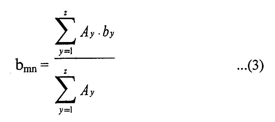
- In Formula (3), "A" indicates an area of a portion of the mask, z is the number of portions of the mask, and b is the image data of a pixel area including the area A on the first virtual screen. Therefore, y is an integer from 1 to the total number of portions z of the mask.
- FIG. 10A shows an example of the superimposition of the virtual screens VDS-VSS on which a circular mask is laid on each blue sub-pixel area as the result of performing step S4 shown in FIG. 4 when a ratio of the new resolution of the input image data to the resolution of the display panel is 1.5:1. FIG. 10B shows an enlarged view of a hatched mask Mnm shown in FIG. 10A in order to explain an algorithm used in step S5 shown in FIG. 4. The mask Mnm is for a blue sub-pixel at an n-th place in a horizontal direction and an m-th place in a vertical direction. In FIG. 10B, a reference character ALU denotes the area of an upper left pixel portion, a reference character ARU denotes the area of an upper right pixel portion, a reference character ALL denotes the area of a lower left pixel portion, and a reference character ARL denotes the area of a lower right pixel portion. The description of FIGS. 10A and 10B is the same as that of FIGS. 8A and 8B, and is thus omitted. Meanwhile, circular masks are ideal in theory, but in practice some pixel areas are used twice and some pixel areas are not used at all in obtaining output image data. Accordingly, circular masks are less preferable than quadrilateral and hexagonal masks. However, it is preferable that the shape of masks is the same as the shape of sub-pixels of a display panel.
- FIG. 11 shows sub-pixel areas on the second virtual screen VDS, which are disposed at different horizontal and vertical positions with respect to unit pixel areas on the first virtual screen VSS when a ratio of the new resolution of the input image data to the resolution of the display panel is 1.4:1. In FIG. 11, areas defined by solid lines are pixel areas on the first virtual screen VSS, and areas defined by dotted lines are sub-pixel areas on the second virtual screen VDS. On the second virtual screen VDS, areas having a circle at their center are red sub-pixel areas, areas having a square at their center are green sub-pixel areas, and areas having a diamond at their center are blue sub-pixel areas. Referring to FIG. 11, the number of different horizontal positions of sub-pixel areas is 15, and the number of different vertical positions thereof is 10. In other words, 150 masks must be used in step S4 shown in FIG.4. Accordingly, in step S6, the number of times , that area ratios are multiplied by transformed image data, relatively increases, thereby decreasing display speed and increasing necessary memory-capacity.
- FIG. 12 shows sub-pixel areas on the second virtual screen VDS, which are disposed at different horizontal and vertical positions with respect to unit pixel areas on the first virtual screen VSS when a ratio of the new resolution of the input image data to the resolution of the display panel is 1.5:1. In FIG. 12, areas defined by solid lines are pixel areas on the first virtual screen VSS. On the second virtual screen VDS, areas having a circle at their center are red sub-pixel areas, areas having a square at their center are green sub-pixel areas, and areas having a diamond at their center are blue sub-pixel areas. Referring to FIG. 12, the number of different horizontal positions of sub-pixel areas is 0, and the number of different vertical positions thereof is 4. In other words, only 4 masks are used in step S4 shown in FIG. 4. Accordingly, in step S6, the number of times area ratios are multiplied by transformed image data decreases, thereby increasing display speed. For example, an area ratio table shown in Table 1 is obtained in step S5 shown in FIG. 4.
Pixel-area positions Sums 1 2 3 4 5 6 7 Masks A 2 1 16 8 6 3 36 B 10 5 14 7 36 C 7 14 5 10 36 D 3 6 8 16 1 2 36 - Here, the mask shown in FIG. 8B corresponds to the mask C in Table 1. Referring to FIG. 8B and mask C in Table 1, the area ALL has area ratio of 7, the area ARL has area ratio of 14, the area ALU has area ratio of 5, and the area ARU has area ratio of 10.
- Therefore, it can be inferred from FIGS. 11 and 12 that the number of masks to be used is minimized by performing step S1 shown in FIG. 4.
- FIG. 13A is a graph of the number of different horizontal positions with respect to a horizontal resolution ratio when the sub-pixel areas of a display panel have a delta structure. Here, the delta structure is a sub-pixel array structure shown in the second virtual screen VDS of FIG. 3. Referring to FIG. 13A, it is preferable to set a new horizontal resolution for input image data such that a ratio of the new horizontal resolution to the horizontal resolution of the display panel is 1:1, 1.5:1, or 2:1.
- FIG. 13B is a graph of the number of different vertical positions with respect to a vertical resolution ratio when the sub-pixel areas of a display panel have a delta structure. Referring to FIG. 13B, it is preferable to set a new vertical resolution for input image data such that a ratio of the new vertical resolution to the vertical resolution of the display panel is 1:1, 1.2:1, 1.5:1, 1.6:1, or 2:1.
- FIG. 14 is a graph of the number of masks with respect to a resolution ratio when the sub-pixel areas of a display panel have a striped structure. In this case, a resolution ratio means a vertical resolution ratio and a horizontal resolution ratio which are the same. In the striped structure, red sub-pixel areas are positioned on a first line, green sub-pixel areas are positioned on a second line, and blue sub-pixel areas are positioned on a third line. The detailed data of the graph shown in FIG. 14 is shown in Tables 2A through 2C.
resolution ratio 1:1 1.1:1 1.2:1 1.3:1 1.4:1 1.5:1 Number of masks 3 300 25 300 75 4 resolution ratio 1.6:1 1.7:1 1.8:1 1.9:1 2.0:1 2.1:1 Number of masks 75 Over 1000 25 Over 1000 3 100 resolution ratio 2.2:1 2.3:1 2.4:1 2.5:1 2.6:1 --------- Number of masks 75 300 500 12 75 --------- - A delta type structure of the sub-pixel areas of a display panel is more preferable than a striped structure because in a stripe type structure, the sub-pixels that are located on the up and down side of a certain sub-pixel are of the same color so that the first imaginary image cells which are vertically located of a certain sub-pixel and overlapped by a mask are less effective to the sub-pixel in the process of sub-pixel rendering than delta type structure.
- FIG. 15 is a graph of the number of masks with respect to a resolution ratio when the sub-pixel areas of a display panel have a delta structure. In this case, a resolution ratio means a vertical resolution ratio and a horizontal resolution ratio which are the same. The detailed data of the graph shown in FIG. 15 is shown in Tables 3A through 3C.
resolution ratio 1:1 1.1:1 1.2:1 1.3:1 1.4:1 1.5:1 Number of masks 6 300 25 300 150 4 resolution ratio 1.6:1 1.7:1 1.8:1 1.9:1 2.0:1 2.1:1 Number of masks 75 Over 2000 25 Over 2000 3 100 resolution ratio 2.2:1 2.3:1 2.4:1 2.5:1 2.6:1 --------- Number of masks 150 300 500 12 150 --------- - In the meantime, when a second virtual screen is superimposed on a first virtual screen, it is preferable that the central line of each pixel area on the first virtual screen is not the central line of each sub-pixel area on the second virtual screen. The reason will be described below.
- FIG. 16A shows a state in which the central line of a pixel area on a first virtual screen is the central line of a sub-pixel area on a second virtual screen. FIG. 16B shows a state in which the central line of a pixel area on a first virtual screen is not the central line of a sub-pixel area on a second virtual screen. In FIGS. 16A and 16B, reference characters VP11 through VP23 denote some pixel areas on the first virtual screen. A reference character CR22 denotes a red sub-pixel area on the second virtual screen, a reference character CG22 denotes a green sub-pixel area on the second virtual screen, and a reference character CB22 denotes a blue sub-pixel area on the second virtual screen. A reference character MR22 denotes a mask for the red sub-pixel area CR22, a reference character MG22 denotes a mask for the green sub-pixel area CG22, and a reference character MB22 denotes a mask for the blue sub-pixel area CB22.
- Referring to FIG. 16A, the central vertical line of a pixel area on the first virtual screen is the central vertical line of the green sub-pixel area CG22 on the second virtual screen. When steps S4, S5, and S6 are performed in this state, a color error phenomenon in which green is visually conspicuous may occur. When green is conspicuous, a viewer may easily notice the color error phenomenon.
- However, as shown in FIG. 16B, when the central vertical line of a pixel area on the first virtual screen is a middle line between the green and blue sub-pixel areas CG22 and CB22 on the second virtual screen, a mixture of green and blue, i.e., a shade of cyan, may be visually conspicuous. When a shade of cyan is conspicuous, a viewer cannot easily recognize the color error phenomenon.
- Similarly, when the central vertical line of a pixel area on the first virtual screen is a middle line between the red and blue sub-pixel areas CR22 and CB22 on the second virtual screen, a mixture of red and blue, i.e., a shade of magenta, may be visually conspicuous. When a shade of magenta is conspicuous, a viewer cannot easily recognize the color error phenomenon.
- In the meantime, referring to FIGS. 8A and 12, when a ratio of the new resolution of the input image data to the resolution of the display panel is 1.5:1, the central vertical line of a pixel area on the first virtual screen VSS is not the central vertical line of a sub-pixel area on the second virtual screen VDS.
- The present invention is applicable to all types of display devices including for example plasma display panels (PDP), liquid crystal display (LCD) panels and ferroelectric liquid crystal (FLC) panels.
- Devices that can be used for applying the present invention can include for example televisions, computers, and other multimedia or telecommunication devices. For example, as seen in FIG. 17 a device for processing image data to generate output image data for driving a display panel according to the present invention can include the display panel such as a
plasma display panel 100 connected to adisplay controller 102 and adisplay memory 104. The processor orcontroller 106 processes the image data stored in theimage memory 108 and transfers the processed image data to thedisplay memory 104 where the transferred data is managed by thedisplay controller 102 for display on thedisplay panel 100. - FIG. 18 shows another view of a device for processing image data to generate output image data for driving a display panel according to the present invention. The
display panel 100 is controlled bycontroller 112 using memory or computer readable media 114 (e.g. non volatile read-only memory, random access memory, floppy disks, compact discs, digital versatile discs, hard disk drives, flash read-only memories, other optical and magnetic mediums, etc.). - Referring to FIG. 19, another example of a device implementing the present invention is a
display device unit 150 connected to acomputer unit 200 and thecomputer unit 200 is connected to aremote computer 300. Thedisplay panel 100 such as a plasma display panel is driven by adisplay driving unit 120 and is connected to thecomputer unit 200 through theinterface 130 of thedisplay unit 150 anddisplay interface 210 of thecomputer unit 200. Through a system bus, thedisplay interface 210 is connected to computer readable media such as the system memory 220 (read-only memory, random access memory) and storage media 240 (floppy disks, compact discs, digital versatile discs, hard disk drives, flash read-only memories, other optical and magnetic mediums, etc.). The system bus also connects thecomputer processor 230 with the computer readable medium and includes inputs throughinput device 262 and other input andoutput devices 260. Thecomputer unit 200 can also be connected to aremote computer 300 through anetwork interface 250 and anetwork 400 such as the Internet. - As described above, a method of processing image data according to the present invention has the following effects.
- First, a new resolution for input image data can be set in order to maximize the number of masks having the same area ratio structures. Accordingly, the number of masks to be used is minimized, so the number of times area ratios are multiplied by transformed image data is minimized, thereby increasing display speed and decreasing necessary memory-capacity.
- Second, each sub-pixel of a display panel is involved with the data of its adjacent pixels on a first virtual screen, so a problem in reproducing an image due to the sub-pixel array structure of the display panel can be radically solved.
- In addition, a color error, which may occur during data processing, can be corrected.
- The present invention is not restricted to the above-described embodiment, and it will be apparent that various changes can be made by those skilled in the art without departing from the spirit of the invention.
Claims (32)
- A method of processing image data to generate output image data for driving a display panel, the method comprising:setting a new resolution for input image data according to a resolution of said display panel;dividing a first virtual screen into a plurality of pixel areas according to said new resolution set for said input image data;superimposing a second virtual screen including a sub-pixel array structure of said display panel on said first virtual screen;laying a mask wider than a sub-pixel area on the superimposed second virtual screen on each sub-pixel area;obtaining and setting an area ratio of the area of each pixel portion on said first virtual screen included in each mask to an area of said mask; andapplying said new resolution and the area ratios to a driving device of said display panel, transforming said input image data having an original resolution into image data having said new resolution, and generating a sum of the results of multiplying area ratios of pixel portions on the first virtual screen in each mask by the transformed image data of the pixel areas, respectively, as output image data of the sub-pixel corresponding to said mask.
- The method of claim 1, with the new resolution for the input image data being set to maximize the number of masks having the same area ratio structures.
- The method of claim 2, with the setting of said new resolution comprising:setting a new horizontal resolution for said input image data according to a horizontal resolution of said display panel; andsetting a new vertical resolution for said input image data according to a vertical resolution of said display panel.
- The method of claim 3, with said new horizontal resolution being set to accommodate a ratio of said new horizontal resolution for the input image data to said horizontal resolution of said display panel being one among 1:1, 1.5:1, and 2:1.
- The method of claim 3, with said new vertical resolution being set to accommodate said new vertical resolution for said input image data to said vertical resolution of said display panel being one among 1:1, 1.2:1, 1.5:1, 1.6:1, and 2:1.
- The method of any preceding claim wherein, when said second virtual screen is superimposed on said first virtual screen, the central line of each pixel area on said first virtual screen is not the central line of each sub-pixel area on said second virtual screen.
- The method of any preceding claim wherein the shape of said masks is the same as said sub-pixels of said display panel.
- The method of any of claims 1 to 7, wherein the shape of said masks is one among a quadrilateral, a hexagon, and a circle.
- The method of claim 8 wherein the shape of said masks being one among a quadrilateral and a hexagon.
- The method of any preceding claim further comprised of the sub-pixel array structure including a delta structure.
- The method of claim 1, wherein said display panel being a plasma display panel.
- The method of claim 3, further comprised of said laying of said mask not including a next same color sub-pixel.
- A method of processing image data according to any preceding claim driving wherein said mask does not cover any portion of a next same color sub-pixel area;
- The method of claim 13, wherein the output image data of a certain sub-pixel generated according to:where A is an area of a portion of said mask,

where z is the number of portions of said mask, and
where b is the image data of a pixel area including the area A on the first virtual screen. - A system for processing image data to generate output image data for driving a display panel, comprising:a computer processor unit processing the image data;a computer readable medium storing the image data;a first unit initializing said computer readable medium;a second unit setting a new resolution for input image data according to a resolution of said display panel;a third unit dividing a first virtual screen into a plurality of pixel areas according to said new resolution set for said input image data;a fourth unit superimposing a second virtual screen including a sub-pixel array structure of said display panel on said first virtual screen;a fifth unit laying a mask wider than a sub-pixel area on the superimposed second virtual screen on each sub-pixel area;a sixth unit obtaining and setting an area ratio of the area of each pixel portion on said first virtual screen included in each mask to an area of said mask; anda seventh unit applying said new resolution and the area ratios to a driving device of said display panel, transforming said input image data having an original resolution into image data having said new resolution, and generating a sum of the results of multiplying area ratios of pixel portions on the first virtual screen in each mask by the transformed image data of the pixel areas, respectively, as output image data of the sub-pixel corresponding to said mask.
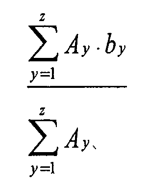
- The system of claim 15, with the output image data of a certain sub-pixel generated according to:where A is an area of a portion of said mask,
where z is the number of portions of said mask, and
where b is the image data of a pixel area including the area A on the first virtual screen. - A system for processing image data to generate output image data for driving a display panel, comprising:a computer readable medium;a processor connected to said computer readable medium, said processor programmed to:setting a new resolution for input image data according to a resolution of said display panel;dividing a first virtual screen into a plurality of pixel areas according to said new resolution set for said input image data;superimposing a second virtual screen including a sub-pixel array structure of said display panel on said first virtual screen;laying a mask wider than a sub-pixel area on the superimposed second virtual screen on each sub-pixel area;obtaining and setting an area ratio of the area of each pixel portion on said first virtual screen included in each mask to an area of said mask; andapplying said new resolution and the area ratios to a driving device of said display panel, transforming said input image data having an original resolution into image data having said new resolution, and generating a sum of the results of multiplying area ratios of pixel portions on the first virtual screen in each mask by the transformed image data of the pixel areas, respectively, as output image data of the sub-pixel corresponding to said mask.
- The system of claim 16 or 17, with the new resolution for the input image data being set to maximize the number of masks having the same area ratio structures.
- The system of claim 18, with said second unit setting of said new resolution comprising:setting a new horizontal resolution for said input image data according to a horizontal resolution of said display panel; andsetting a new vertical resolution for said input image data according to a vertical resolution of said display panel.
- The system of claim 19, with said new horizontal resolution being set to accommodate a ratio of said new horizontal resolution for the input image data to said horizontal resolution of said display panel being one among 1:1, 1.5:1, and 2:1.
- The system of claim 19, with said new vertical resolution being set to accommodate said new vertical resolution for said input image data to said vertical resolution of said display panel being one among 1:1, 1.2:1, 1.5:1, 1.6:1, and 2:1.
- The system of claim 21, further comprised of said fourth unit including when said second virtual screen is superimposed on said first virtual screen, the central line of each pixel area on said first virtual screen not being the central line of each sub-pixel area on said second virtual screen.
- The system of claim 22, further comprised of a shape of said masks being the same as said sub-pixels of said display panel.
- The system of claim 22, further comprised of a shape of said masks being one among a quadrilateral, a hexagon, and a circle.
- The system of claim 22, further comprised of a shape of said masks being one among a quadrilateral and a hexagon.
- The system of claim 25, further comprised of when said second virtual screen is superimposed on said first virtual screen, the central line of each pixel area on said first virtual screen not being the central line of each sub-pixel area on said second virtual screen.
- The system of any of claims 15 to 26, further comprised of the sub-pixel array structure being a delta structure.
- The system of any of claims 15 to 27, with said display panel being a plasma display panel.
- The system of any of claims 15 to 28, further comprised of said laying of said mask not including a next same color sub-pixel.
- A computer-readable medium having computer-executable instructions for performing a method according to any of claims 1 to 14.
- A computer-readable medium having stored thereon a data structure comprising:a first field containing data representing a new resolution for input image data according to a resolution of a plasma display panel;a second field containing data representing a dividing of a first virtual screen into a plurality of pixel areas according to said new resolution set for said input image data;a third field containing data representing a superimposing of a second virtual screen including a sub-pixel array structure of said plasma display panel on said first virtual screen;a fourth field containing data representing laying a mask on the superimposed second virtual screen on each sub-pixel area, said mask not covering any portion of a next same color sub-pixel area;a fifth field containing data representing obtaining and setting an area ratio of the area of each pixel portion on said first virtual screen included in each mask to an area of said mask; anda sixth field containing data representing applying said new resolution and the area ratios to a driving device of said plasma display panel, transforming said input image data having an original resolution into image data having said new resolution, and generating a sum of the results of multiplying area ratios of pixel portions on the first virtual screen in each mask by the transformed image data of the pixel areas, respectively, as output image data of the sub-pixel corresponding to said mask.
- A method of processing image data to generate output image data for driving a plasma display panel, the method comprising:dividing a first virtual screen into a plurality of pixel areas according to a new resolution generated from an original resolution for said input image data;superimposing a second virtual screen including a delta type sub-pixel array structure of said plasma display panel on said first virtual screen;laying a mask wider than a sub-pixel area on the superimposed second virtual screen on each sub-pixel area, said mask not covering a portion of a next same color sub-pixel area;setting an area ratio of the area of each pixel portion on said first virtual screen included in each mask to an area of said mask; andapplying said new resolution and the area ratios to a driving device of said plasma display panel, transforming said input image data having an original resolution into image data having said new resolution, and generating a sum of the results of multiplying area ratios of pixel portions on the first virtual screen in each mask by the transformed image data of the pixel areas, respectively, as output image data of the sub-pixel corresponding to said mask.
Applications Claiming Priority (2)
| Application Number | Priority Date | Filing Date | Title |
|---|---|---|---|
| KR2002067967 | 2002-11-04 | ||
| KR10-2002-0067967A KR100436715B1 (en) | 2002-11-04 | 2002-11-04 | Method of fast processing image data for improving reproducibility of image |
Publications (2)
| Publication Number | Publication Date |
|---|---|
| EP1416468A2 true EP1416468A2 (en) | 2004-05-06 |
| EP1416468A3 EP1416468A3 (en) | 2005-07-27 |
Family
ID=32089789
Family Applications (1)
| Application Number | Title | Priority Date | Filing Date |
|---|---|---|---|
| EP03254131A Ceased EP1416468A3 (en) | 2002-11-04 | 2003-06-27 | Method of fast processing image data for improving image visibility |
Country Status (5)
| Country | Link |
|---|---|
| US (1) | US6958761B2 (en) |
| EP (1) | EP1416468A3 (en) |
| JP (1) | JP4194432B2 (en) |
| KR (1) | KR100436715B1 (en) |
| CN (1) | CN1499477A (en) |
Cited By (1)
| Publication number | Priority date | Publication date | Assignee | Title |
|---|---|---|---|---|
| EP1675090A4 (en) * | 2004-07-30 | 2008-10-08 | Hitachi Ltd | IMAGE DISPLAY APPARATUS AND IMAGE DISPLAY METHOD |
Families Citing this family (20)
| Publication number | Priority date | Publication date | Assignee | Title |
|---|---|---|---|---|
| CN100513174C (en) * | 2004-07-06 | 2009-07-15 | 佳能株式会社 | Data processing method, data processing apparatus, mask generation method, and mask pattern |
| KR101208724B1 (en) * | 2005-01-03 | 2012-12-06 | 삼성디스플레이 주식회사 | Array substrate and display panel having the same |
| JP4777675B2 (en) * | 2005-03-17 | 2011-09-21 | 株式会社リコー | Image processing apparatus, image display apparatus, image processing method, program for causing computer to execute the method, and recording medium |
| CN100422924C (en) * | 2005-04-30 | 2008-10-01 | 广东威创视讯科技股份有限公司 | Computer structure for displaying single whole desktop by multiple output channels |
| US8049685B2 (en) * | 2006-11-09 | 2011-11-01 | Global Oled Technology Llc | Passive matrix thin-film electro-luminescent display |
| KR101271098B1 (en) * | 2008-09-24 | 2013-06-04 | 삼성테크윈 주식회사 | Digital photographing apparatus, method for tracking, and recording medium storing program to implement the method |
| CN102982536B (en) * | 2012-11-05 | 2015-07-22 | 华为技术有限公司 | Image processing method and device |
| CN103927946B (en) | 2014-03-25 | 2016-06-08 | 京东方科技集团股份有限公司 | Display packing |
| CN103903549B (en) * | 2014-03-25 | 2016-08-17 | 京东方科技集团股份有限公司 | Display packing |
| CN103915044B (en) * | 2014-03-25 | 2016-03-30 | 京东方科技集团股份有限公司 | Display packing |
| CN104157231B (en) | 2014-07-23 | 2016-08-17 | 京东方科技集团股份有限公司 | The display methods of a kind of image and display device |
| CN104680994B (en) * | 2015-03-09 | 2017-09-15 | 深圳市华星光电技术有限公司 | The driving method and drive device of a kind of liquid crystal display |
| CN104658503B (en) * | 2015-03-09 | 2017-05-10 | 深圳市华星光电技术有限公司 | Driving method and driving device of liquid crystal display |
| CN104680966B (en) * | 2015-03-19 | 2017-11-14 | 京东方科技集团股份有限公司 | The driving method and its drive device of a kind of display device |
| CN106157876B (en) * | 2015-03-27 | 2019-04-23 | 上海和辉光电有限公司 | The display methods and display of display image |
| KR102389196B1 (en) * | 2015-10-05 | 2022-04-22 | 엘지디스플레이 주식회사 | Display device and image rendering method thereof |
| CN107941256B (en) * | 2017-11-20 | 2020-03-06 | 中国电子科技集团公司第四十一研究所 | A Numerical Personalized Display Method of High Precision Measuring Instrument |
| CN110428354B (en) * | 2019-06-25 | 2023-04-07 | 福建华佳彩有限公司 | Panel sampling method, storage medium and computer |
| CN112185304B (en) * | 2020-09-28 | 2022-06-24 | 南京芯视元电子有限公司 | Video display system and method for reducing storage capacity and improving display resolution |
| CN117894269B (en) * | 2024-03-14 | 2024-07-02 | 集创北方(珠海)科技有限公司 | Data processing method, processing device and chip |
Citations (1)
| Publication number | Priority date | Publication date | Assignee | Title |
|---|---|---|---|---|
| WO2002077956A2 (en) * | 2001-03-27 | 2002-10-03 | Koninklijke Philips Electronics N.V. | Display device and method of displaying an image |
Family Cites Families (40)
| Publication number | Priority date | Publication date | Assignee | Title |
|---|---|---|---|---|
| US632896A (en) * | 1898-09-14 | 1899-09-12 | Whitfield Company | Combined engine and dynamo. |
| JPS57138685A (en) * | 1981-02-23 | 1982-08-27 | Hitachi Ltd | Graphic conversion for graphic indicator |
| JPS60120398A (en) * | 1983-12-02 | 1985-06-27 | シチズン時計株式会社 | Matrix type color display unit |
| US5341153A (en) * | 1988-06-13 | 1994-08-23 | International Business Machines Corporation | Method of and apparatus for displaying a multicolor image |
| US5682180A (en) * | 1990-06-08 | 1997-10-28 | General Motors Corporation | Multi-color electronic display utilizing opponent colors |
| US5426723A (en) * | 1992-03-09 | 1995-06-20 | Spacelabs Medical, Inc. | System and method for scaling graphic images |
| JP2797883B2 (en) | 1993-03-18 | 1998-09-17 | 株式会社日立製作所 | Multicolor light emitting device and its substrate |
| KR100259783B1 (en) | 1994-03-11 | 2000-06-15 | 미다라이 후지오 | Display pixel balancing for multiple color individual level displays |
| US5796378A (en) | 1994-03-29 | 1998-08-18 | Casio Computer Co., Ltd. | Birifringence control type liquid crystal display device and apparatus and method of driving the same |
| TW295652B (en) | 1994-10-24 | 1997-01-11 | Handotai Energy Kenkyusho Kk | |
| JP3309593B2 (en) | 1994-10-28 | 2002-07-29 | 松下電器産業株式会社 | Plasma display |
| US5959598A (en) | 1995-07-20 | 1999-09-28 | The Regents Of The University Of Colorado | Pixel buffer circuits for implementing improved methods of displaying grey-scale or color images |
| US6031626A (en) | 1996-08-15 | 2000-02-29 | Seiko Epson Corporation | Color stochastic screening with optimal color dot placement |
| US5963715A (en) | 1996-08-15 | 1999-10-05 | Seiko Epson Corporation | Color stochastic screening with optimal color dot placement for display devices having arbitrary aspect ratios |
| US6046716A (en) | 1996-12-19 | 2000-04-04 | Colorado Microdisplay, Inc. | Display system having electrode modulation to alter a state of an electro-optic layer |
| US5920298A (en) | 1996-12-19 | 1999-07-06 | Colorado Microdisplay, Inc. | Display system having common electrode modulation |
| US6078303A (en) | 1996-12-19 | 2000-06-20 | Colorado Microdisplay, Inc. | Display system having electrode modulation to alter a state of an electro-optic layer |
| US6020868A (en) | 1997-01-09 | 2000-02-01 | Rainbow Displays, Inc. | Color-matching data architectures for tiled, flat-panel displays |
| JPH10254370A (en) | 1997-03-10 | 1998-09-25 | Canon Inc | Display panel and projection display device using the same |
| US5913591A (en) * | 1998-01-20 | 1999-06-22 | University Of Washington | Augmented imaging using a silhouette to improve contrast |
| US6100861A (en) | 1998-02-17 | 2000-08-08 | Rainbow Displays, Inc. | Tiled flat panel display with improved color gamut |
| US6281875B1 (en) * | 1998-04-29 | 2001-08-28 | Canon Kabushiki Kaisha | Gradient-based pixel interpolation |
| EP2439730A1 (en) | 1998-10-07 | 2012-04-11 | Microsoft Corporation | Independent mapping of portions of color image data to pixel sub-components |
| US6356278B1 (en) | 1998-10-07 | 2002-03-12 | Microsoft Corporation | Methods and systems for asymmeteric supersampling rasterization of image data |
| US6188385B1 (en) | 1998-10-07 | 2001-02-13 | Microsoft Corporation | Method and apparatus for displaying images such as text |
| US6307566B1 (en) | 1998-10-07 | 2001-10-23 | Microsoft Corporation | Methods and apparatus for performing image rendering and rasterization operations |
| US6278434B1 (en) | 1998-10-07 | 2001-08-21 | Microsoft Corporation | Non-square scaling of image data to be mapped to pixel sub-components |
| US6236390B1 (en) | 1998-10-07 | 2001-05-22 | Microsoft Corporation | Methods and apparatus for positioning displayed characters |
| US6393145B2 (en) | 1999-01-12 | 2002-05-21 | Microsoft Corporation | Methods apparatus and data structures for enhancing the resolution of images to be rendered on patterned display devices |
| US6342890B1 (en) | 1999-03-19 | 2002-01-29 | Microsoft Corporation | Methods, apparatus, and data structures for accessing sub-pixel data having left side bearing information |
| US6342896B1 (en) | 1999-03-19 | 2002-01-29 | Microsoft Corporation | Methods and apparatus for efficiently implementing and modifying foreground and background color selections |
| US6339426B1 (en) | 1999-04-29 | 2002-01-15 | Microsoft Corporation | Methods, apparatus and data structures for overscaling or oversampling character feature information in a system for rendering text on horizontally striped displays |
| US6282327B1 (en) | 1999-07-30 | 2001-08-28 | Microsoft Corporation | Maintaining advance widths of existing characters that have been resolution enhanced |
| US6738526B1 (en) | 1999-07-30 | 2004-05-18 | Microsoft Corporation | Method and apparatus for filtering and caching data representing images |
| US6226017B1 (en) | 1999-07-30 | 2001-05-01 | Microsoft Corporation | Methods and apparatus for improving read/modify/write operations |
| US6384839B1 (en) | 1999-09-21 | 2002-05-07 | Agfa Monotype Corporation | Method and apparatus for rendering sub-pixel anti-aliased graphics on stripe topology color displays |
| KR100408213B1 (en) | 2000-06-26 | 2003-12-01 | 황기웅 | an AC plasma display panel having delta color pixels of closed shape subpixels |
| KR20020008040A (en) | 2000-07-18 | 2002-01-29 | 마츠시타 덴끼 산교 가부시키가이샤 | Display apparatus, display method, and recording medium which the display control program is recorded |
| CN1179312C (en) | 2000-07-19 | 2004-12-08 | 松下电器产业株式会社 | display method |
| KR100446631B1 (en) * | 2002-08-24 | 2004-09-04 | 삼성전자주식회사 | Method and apparatus for rendering color image on delta structured displays |
-
2002
- 2002-11-04 KR KR10-2002-0067967A patent/KR100436715B1/en not_active Expired - Fee Related
-
2003
- 2003-04-03 US US10/405,909 patent/US6958761B2/en not_active Expired - Fee Related
- 2003-06-27 EP EP03254131A patent/EP1416468A3/en not_active Ceased
- 2003-06-30 JP JP2003188436A patent/JP4194432B2/en not_active Expired - Fee Related
- 2003-06-30 CN CNA031483372A patent/CN1499477A/en active Pending
Patent Citations (1)
| Publication number | Priority date | Publication date | Assignee | Title |
|---|---|---|---|---|
| WO2002077956A2 (en) * | 2001-03-27 | 2002-10-03 | Koninklijke Philips Electronics N.V. | Display device and method of displaying an image |
Cited By (1)
| Publication number | Priority date | Publication date | Assignee | Title |
|---|---|---|---|---|
| EP1675090A4 (en) * | 2004-07-30 | 2008-10-08 | Hitachi Ltd | IMAGE DISPLAY APPARATUS AND IMAGE DISPLAY METHOD |
Also Published As
| Publication number | Publication date |
|---|---|
| CN1499477A (en) | 2004-05-26 |
| JP2004157514A (en) | 2004-06-03 |
| US6958761B2 (en) | 2005-10-25 |
| EP1416468A3 (en) | 2005-07-27 |
| KR100436715B1 (en) | 2004-06-22 |
| KR20040039783A (en) | 2004-05-12 |
| US20040085333A1 (en) | 2004-05-06 |
| JP4194432B2 (en) | 2008-12-10 |
Similar Documents
| Publication | Publication Date | Title |
|---|---|---|
| US6958761B2 (en) | Method of fast processing image data for improving visibility of image | |
| CN101097674B (en) | Flat panel display and method of controlling image quality thereof | |
| JP3792246B2 (en) | Crosstalk elimination circuit, liquid crystal display device, and display control method | |
| US20050275610A1 (en) | Liquid crystal display device and driving method for the same | |
| US6198467B1 (en) | Method of displaying a high-resolution digital color image on a low-resolution dot-matrix display with high fidelity | |
| US20050231534A1 (en) | Apparatus and method for driving a display device | |
| TW200530976A (en) | Liquid crystal display backplane layouts and addressing for non-standard subpixel arrangements | |
| JP3191093B2 (en) | Color filter pixel array structure, liquid crystal display device using the same, and method of driving the same | |
| JP2006285238A (en) | Display method for use in display device and display device | |
| CN106920525B (en) | Driving method of three-grid driving structure liquid crystal display | |
| CN101937142A (en) | Liquid crystal display device and driving method thereof | |
| WO2000033564A9 (en) | Electronic keystone correction for electronic devices with a visual display | |
| US7218301B2 (en) | System and method of performing dot inversion with standard drivers and backplane on novel display panel layouts | |
| CN101399025A (en) | Liquid crystal display device, operation method thereof and electronic device | |
| EP3012830A1 (en) | Image up-scale unit and method | |
| CN103165088A (en) | Liquid crystal display device and method of driving the same | |
| US20090079674A1 (en) | Liquid crystal display with peep-preventing function | |
| WO2010016319A1 (en) | Image processing device, display device, image processing method, program, and recording medium | |
| CN101292279B (en) | Improved memory structure for image processing | |
| JP2001343636A (en) | Matrix type color display device | |
| JP2020507133A (en) | Driving method of liquid crystal display panel | |
| CN101086824A (en) | LCD pixel structure and its driving method | |
| CN100444243C (en) | A display device and display method using red, green, blue and white color filters | |
| KR100589320B1 (en) | Video display | |
| EP1072154A1 (en) | Method and apparatus for improving video camera output quality |
Legal Events
| Date | Code | Title | Description |
|---|---|---|---|
| PUAI | Public reference made under article 153(3) epc to a published international application that has entered the european phase |
Free format text: ORIGINAL CODE: 0009012 |
|
| AK | Designated contracting states |
Kind code of ref document: A2 Designated state(s): AT BE BG CH CY CZ DE DK EE ES FI FR GB GR HU IE IT LI LU MC NL PT RO SE SI SK TR |
|
| AX | Request for extension of the european patent |
Extension state: AL LT LV MK |
|
| PUAL | Search report despatched |
Free format text: ORIGINAL CODE: 0009013 |
|
| AK | Designated contracting states |
Kind code of ref document: A3 Designated state(s): AT BE BG CH CY CZ DE DK EE ES FI FR GB GR HU IE IT LI LU MC NL PT RO SE SI SK TR |
|
| AX | Request for extension of the european patent |
Extension state: AL LT LV MK |
|
| RIC1 | Information provided on ipc code assigned before grant |
Ipc: 7G 09G 3/20 B Ipc: 7G 09G 5/37 A |
|
| 17P | Request for examination filed |
Effective date: 20051130 |
|
| AKX | Designation fees paid |
Designated state(s): DE FR GB NL |
|
| STAA | Information on the status of an ep patent application or granted ep patent |
Free format text: STATUS: THE APPLICATION HAS BEEN REFUSED |
|
| 18R | Application refused |
Effective date: 20081117 |