EP1416442A2 - Diagnostic imaging apparatus for obtaining characteristic quantity based on positional relationship between positions of interest in images of object - Google Patents
Diagnostic imaging apparatus for obtaining characteristic quantity based on positional relationship between positions of interest in images of object Download PDFInfo
- Publication number
- EP1416442A2 EP1416442A2 EP03025022A EP03025022A EP1416442A2 EP 1416442 A2 EP1416442 A2 EP 1416442A2 EP 03025022 A EP03025022 A EP 03025022A EP 03025022 A EP03025022 A EP 03025022A EP 1416442 A2 EP1416442 A2 EP 1416442A2
- Authority
- EP
- European Patent Office
- Prior art keywords
- images
- interest
- radiographic
- predetermined part
- positions
- Prior art date
- Legal status (The legal status is an assumption and is not a legal conclusion. Google has not performed a legal analysis and makes no representation as to the accuracy of the status listed.)
- Granted
Links
Images


Classifications
-
- G—PHYSICS
- G06—COMPUTING OR CALCULATING; COUNTING
- G06T—IMAGE DATA PROCESSING OR GENERATION, IN GENERAL
- G06T7/00—Image analysis
- G06T7/0002—Inspection of images, e.g. flaw detection
- G06T7/0012—Biomedical image inspection
-
- G—PHYSICS
- G06—COMPUTING OR CALCULATING; COUNTING
- G06T—IMAGE DATA PROCESSING OR GENERATION, IN GENERAL
- G06T7/00—Image analysis
- G06T7/60—Analysis of geometric attributes
Definitions
- the present invention relates to a diagnostic imaging apparatus which outputs information on a predetermined part of an object based on a plurality of images of the predetermined part which are taken during movement of the predetermined part.
- radiographic-image recording apparatuses Conventionally, various radiographic-image recording apparatuses have been proposed, where those radiographic-image recording apparatuses apply radiation to an object such as a human body, and record a radiographic image by exposing a film or the like to the radiation which has passed through the object.
- the first type of radiographic-image recording apparatuses use a solid-state radiation detector which records a radiographic image by storing electric charges generated by application of radiation, where the quantities of the stored electric charges correspond to exposure doses.
- the second type of radiographic-image recording apparatuses use an accumulative fluorescent sheet, which is constituted by a base and an accumulative fluorescent layer formed on the base. The accumulative fluorescent layer stores portions of radiation energy, and emits stimulated phosphorescent light according to the stored radiation energy when excitation light is applied to the accumulative fluorescent layer.
- the radiographic images recorded by the above radiographic-image recording apparatuses are developed in a radiographic film, or read as an image signal and displayed as a visible image on a monitor based on the image signal.
- physicians can perform image diagnosis by observing the radiographic film or the visible image on the monitor.
- aforementioned document (1) proposes a technique in which contours of a cardiothoracic region (i.e., a region including a thorax and a heart) are automatically detected based on an image signal representing a radiographic image of a chest, the widths of the thorax and the heart are automatically measured based on the automatically detected contours, a cardiothoracic ratio is calculated based on the automatically measured widths, and a diagnosis is performed based on the cardiothoracic ratio.
- a cardiothoracic region i.e., a region including a thorax and a heart
- aforementioned document (2) proposes a technique in which measurement points in a spine image are automatically set based on an image signal representing a radiographic image of a spine, a characteristic quantity is automatically measured in accordance with a measurement method which is stored in advance, and image diagnosis is performed based on the automatically measured characteristic quantity.
- the radiographic images which are produced by the conventional radiographic-image recording apparatuses and provided for image diagnosis are still images. Therefore, it is impossible to perform functional diagnosis in which abnormality in a predetermined part (e.g., a joint) of a human body which appears during movement of the predetermined part is diagnosed, although morphological diagnosis can be performed.
- a predetermined part e.g., a joint
- the present invention has been developed in view of the above circumstances.
- a diagnostic imaging apparatus comprising: a position-of-interest determination unit which determines a plurality of positions in a plurality of images of a predetermined part of an object which are taken during movement of the predetermined part, to be positions of interest in the plurality of images, where the plurality of positions in the plurality of images correspond to a predetermined position in the predetermined part; and a characteristic-quantity calculation unit which calculates a characteristic quantity indicating a positional relationship between the positions of interest in the plurality of images.
- the plurality of images of the predetermined part are taken while the predetermined part is being intentionally moved by the person as the object, or by another person.
- one of the plurality of images may be taken at the time at which the movement of the predetermined part begins or ends.
- the positions of interest may correspond to a head of humerus, a capitulum of humerus, or a styloid process in the case where the predetermined part is a joint of an arm, or a head of femur or an apex of patella in the case where the predetermined part is a joint of a leg.
- the characteristic quantity may be the distance between the position of interest in the first one of the plurality of images and the corresponding position of interest in the second one of the plurality of images, the direction from the position of interest in the first one of the plurality of images to the corresponding position of interest in the second one of the plurality of images, or a path of a movement from the position of interest in the first one of the plurality of images to the corresponding position of interest in the second one of the plurality of images.
- the diagnostic imaging apparatus may further comprise an automatic diagnosis unit which outputs information on the predetermined part of the object, based on the characteristic quantity.
- the information on the predetermined part may be information which is derived from the characteristic quantity and is directly related to diagnosis, e.g., information indicating whether or not the predetermined part is normal or information indicating a degree of abnormality of the predetermined part.
- information indicating whether or not the predetermined part is normal or information indicating a degree of abnormality of the predetermined part may be output.
- the predetermined part may be a joint of a human body. In this case, it is possible to easily perform functional diagnosis of the joint.
- the plurality of images may be a plurality of radiographic images which are taken by applying radiation to the predetermined part during the movement of the predetermined part.
- a marker may be attached to the predetermined part, and the position-of-interest determination unit may determine positions of images of the marker which are formed in the plurality of radiographic images by radiations which have passed through the marker, to be the positions of interest, to be the positions of interest. In this case, it is possible to easily determine the positions of interest even when the diagnostic imaging apparatus has a simple construction.
- the above marker may be realized by anything which has a different transmittance from the object and can be discriminated from images around the images of the marker.
- the plurality of radiographic images may be taken by using a solid-state radiation detector which generates and stores electric charges when the solid-state radiation detector is irradiated with radiation. In this case, it is possible to easily take the plurality of images of the predetermined part of the object during the movement of the part.
- FIG. 1 is a block diagram illustrating an outline of a construction of the diagnostic radiographic imaging apparatus according to the embodiment.
- the diagnostic radiographic imaging apparatus of FIG. 1 comprises a solid-state radiation detector 10, a position-of-interest determination unit 20, a characteristic-quantity calculation unit 30, and an automatic diagnosis unit 40.
- the solid-state radiation detector 10 generates and stores electric charges when the solid-state radiation detector 10 is irradiated with a radiation.
- the position-of-interest determination unit 20 selects two radiographic images from among a plurality of radiographic images outputted from the solid-state radiation detector 10, and determines positions of interest in the two radiographic images.
- the characteristic-quantity calculation unit 30 calculates a characteristic quantity which indicates a positional relationship between the positions of interest in the two radiographic images which are determined by the position-of-interest determination unit 20.
- the characteristic-quantity calculation unit 30 outputs information indicating whether or not a predetermined part of a human body is normal, based on the characteristic quantity calculated by the characteristic-quantity calculation unit 30, where the human body is an object of the plurality of radiographic images.
- FIG. 2A is a perspective view illustrating an outline of a construction of the solid-state radiation detector 10 used in the diagnostic radiographic imaging apparatus of FIG. 1, and FIG. 2B is a cross-sectional view of a portion a of the solid-state radiation detector 10.
- an electrode layer 1 allows radiation for recording to pass through.
- the radiation detection layer 2 generates electric charges when the radiation detection layer 2 is irradiated with the radiation which has passed through the electrode layer 1.
- the electric-signal detection layer 3 detects as electric signals the electric charges generated in the radiation detection layer 2.
- each of the detection elements 35 is comprised of a TFT (thin-film transistor) switch 31, a pixel capacitance 32, and a pixel electrode 33.
- FIG. 3 is a schematic plan view of a circuit formed in the electric-signal detection layer 3.
- Each capacitor realized by the pixel electrode 33 and the pixel capacitance 32 stores an electric charge generated in the radiation detection layer 2 by irradiation with the radiation.
- the TFT switch 31 can be controlled on and off through a scanning line 51 (which is provided for each row) by a control signal generated by a scanning-line driver unit 50.
- a scanning line 51 which is provided for each row
- a control signal generated by a scanning-line driver unit 50 a control signal generated by a scanning-line driver unit 50.
- an electric charge stored in the capacitor connected to the TFT switch 31 can be read out.
- an electric signal corresponding to the electric charge can be read out through a signal line 52, an amplifier 53, a multiplexer 54, and an analog-to-digital converter 55.
- the solid-state radiation detector 10 of this embodiment takes a radiographic image of a predetermined part (e.g., a joint in an arm or leg) of a human body at intervals of 0.5 micrometers during movement of the predetermined part. Then, the solid-state radiation detector 10 outputs to the position-of-interest determination unit 20 image signals representing a plurality of radiographic images of the predetermined part which are taken by the solid-state radiation detector 10 at intervals of 0.5 micrometers.
- a predetermined part e.g., a joint in an arm or leg
- the position-of-interest determination unit 20 operates as follows.
- the position-of-interest determination unit 20 selects two radiographic images from among the plurality of radiographic images which are inputted to the position-of-interest determination unit 20. For example, in the case where images of states of an arm during an upward movement of the arm are taken by the solid-state radiation detector 10, a first radiographic image P1 of a first state and a second radiographic image P2 of a second state are selected, where the arm is down in the first state, and the arm is moving upward in the second state.
- the first radiographic image P1 (the first one of the plurality of radiographic images) is a radiographic image of the first state
- the selection of the second radiographic image P2 can be realized by selecting a radiographic image which is inputted when a predetermined time elapses after the first radiographic image P1 is inputted.
- the predetermined time is preset in the position-of-interest determination unit 20.
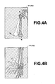
- FIGS. 4A and 4B show corresponding portions in examples of the first and second radiographic images P1 and P2.
- the corresponding portions of the first and second radiographic images P1 and P2 are superimposed on each other, contours in the first radiographic image P1 are indicated by solid lines, and contours in the second radiographic image P2 are indicated by dashed double-dotted lines.
- the position-of-interest determination unit 20 selects two radiographic images from among the plurality of radiographic images inputted into the position-of-interest determination unit 20.
- At least one position of interest in each of the first and second radiographic images P1 and P2 is determined.
- a predetermined point A in a head of humerus, a predetermined point B in a capitulum of humerus and a predetermined point C in a styloid process are determined as positions of interest in the first radiographic image P1.
- the above positions of interest can be determined in any way. For example, it is possible to determine a contour image of bones, and determine each position of interest based on a positional relationship with the contour image. In this case, the positional relationship between the contour image and the position of interest may be preset. Alternatively, it is possible to place in advance a marker exhibiting a different transmittance from a human body with respect to radiations, on a predetermined position around a joint of the human body, take a radiographic image of a part containing the joint and the marker by irradiating the joint with radiation, and determine the position of the image of the marker produced by a portion of the radiation which has passed through the marker, to be the position of interest.
- the marker can be made of, for example, lead, which shades the radiation.
- the image of the marker can be detected by comparing the magnitude of an image signal representing the radiographic image with a predetermined threshold value, and detecting a position of a portion of the radiographic image in which the magnitude of the image signal is greater than the threshold value, as the position of the image of the marker (in the case where the magnitude of the image signal increases with decrease in the transmittance).
- the maker may have any shape which can be detected as a position of interest, for example, a round or rectangular shape.
- points A', B', and C' are determined to be positions of interest in the second radiographic image P2 in correspondence with the points of interest A, B, and C in the first radiographic image P1.
- the position-of-interest determination unit 20 outputs to the characteristic-quantity calculation unit 30 the coordinates of positions of interest in the first and second radiographic images P1 and P2 which are determined as above. Then, the characteristic-quantity calculation unit 30 calculates, based on the above coordinates, the distances between the points A and A', B and B', and C and C' as the characteristic quantities corresponding to the positions of interest A, B, and C.
- the calculated characteristic quantities for the points A, B, and C are outputted to the automatic diagnosis unit 40, in which characteristic quantities for a normal human body and sick human bodies having predetermined diseases are stored in advance.
- the automatic diagnosis unit 40 compares the calculated characteristic quantities corresponding to the points A, B, and C with the characteristic quantities for the normal and sick human bodies. For example, when the calculated characteristic quantities are close to the characteristic quantities for the normal human body, the automatic diagnosis unit 40 outputs information indicating that the examined part of the object is normal. On the other hand, when the calculated characteristic quantities are close to characteristic quantities corresponding to a human body having one of the predetermined diseases, the automatic diagnosis unit 40 outputs information indicating the disease.
- the information indicating that the examined object is normal or the information indicating a disease may be displayed on a display means such as a monitor.
- a plurality of radiographic images of predetermined part (e.g., a joint) of a human body are taken during movement of the predetermined part, and positions in the plurality of radiographic images corresponding to a predetermined position around the predetermined part are determined to be positions of interest. Then, at least one characteristic quantity indicating a positional relationship between the corresponding positions in the plurality of radiographic images is calculated, and information indicating whether or not the predetermined part of the human body is normal is outputted based on the at least one characteristic quantity. Therefore, it is possible to easily perform functional diagnosis of the predetermined part, as well as morphological diagnosis, based on the above information.
- the diagnostic radiographic imaging apparatus according to the present embodiment can be modified as follows.
Landscapes
- Engineering & Computer Science (AREA)
- Physics & Mathematics (AREA)
- Computer Vision & Pattern Recognition (AREA)
- Theoretical Computer Science (AREA)
- General Physics & Mathematics (AREA)
- Medical Informatics (AREA)
- Quality & Reliability (AREA)
- Radiology & Medical Imaging (AREA)
- Nuclear Medicine, Radiotherapy & Molecular Imaging (AREA)
- Health & Medical Sciences (AREA)
- General Health & Medical Sciences (AREA)
- Geometry (AREA)
- Apparatus For Radiation Diagnosis (AREA)
- Image Processing (AREA)
- Image Analysis (AREA)
Abstract
Description
Claims (6)
- A diagnostic imaging apparatus comprising:a position-of-interest determination unit which determines a plurality of positions in a plurality of images of a predetermined part of an object which are taken during a movement of the predetermined part, to be positions of interest in the plurality of images, where the plurality of positions in the plurality of images correspond to a predetermined position in the predetermined part; anda characteristic-quantity calculation unit which calculates a characteristic quantity indicating a positional relationship between the positions of interest in the plurality of images.
- A diagnostic imaging apparatus according to claim 1, further comprising an automatic diagnosis unit which outputs information on said predetermined part of said object, based on said characteristic quantity.
- A diagnostic imaging apparatus according to either one of claims 1 and 2, wherein said predetermined part is a joint of a human body.
- A diagnostic imaging apparatus according to either one of claims 1 to 3, wherein said plurality of images are a plurality of radiographic images which are taken by applying a radiation to said predetermined part during the movement of the predetermined part.
- A diagnostic imaging apparatus according to claim 4, wherein a marker is attached to said predetermined part, said plurality of images are a plurality of radiographic images, and said position-of-interest determination unit determines positions of images of said marker to be said positions of interest, where said images of the marker are respectively formed in said plurality of radiographic images by radiations which have passed through the marker.
- A diagnostic imaging apparatus according to either one of claims 4 and 5, wherein said plurality of radiographic images are taken by using a solid-state radiation detector which generates and stores electric charges when the solid-state radiation detector is irradiated with a radiation.
Applications Claiming Priority (2)
| Application Number | Priority Date | Filing Date | Title |
|---|---|---|---|
| JP2002317609A JP2004147930A (en) | 2002-10-31 | 2002-10-31 | Image diagnostic apparatus |
| JP2002317609 | 2002-10-31 |
Publications (3)
| Publication Number | Publication Date |
|---|---|
| EP1416442A2 true EP1416442A2 (en) | 2004-05-06 |
| EP1416442A3 EP1416442A3 (en) | 2005-01-05 |
| EP1416442B1 EP1416442B1 (en) | 2007-02-14 |
Family
ID=32089573
Family Applications (1)
| Application Number | Title | Priority Date | Filing Date |
|---|---|---|---|
| EP03025022A Expired - Lifetime EP1416442B1 (en) | 2002-10-31 | 2003-10-30 | Imaging apparatus for automatic diagnosis based on a positional relationship of positions of interest across a plurality of images of an object |
Country Status (4)
| Country | Link |
|---|---|
| US (1) | US20040091140A1 (en) |
| EP (1) | EP1416442B1 (en) |
| JP (1) | JP2004147930A (en) |
| DE (1) | DE60311727T2 (en) |
Families Citing this family (7)
| Publication number | Priority date | Publication date | Assignee | Title |
|---|---|---|---|---|
| WO2006027734A1 (en) * | 2004-09-09 | 2006-03-16 | Koninklijke Philips Electronics N.V. | System for the three-dimensional imaging of a moving joint |
| CA2683717C (en) * | 2007-04-19 | 2016-10-11 | Mako Surgical Corp. | Implant planning using captured joint motion information |
| EP2242453B1 (en) | 2008-02-20 | 2018-11-28 | Mako Surgical Corp. | Implant planning using corrected captured joint motion information |
| US9364291B2 (en) * | 2008-12-11 | 2016-06-14 | Mako Surgical Corp. | Implant planning using areas representing cartilage |
| CN103239253B (en) | 2012-02-14 | 2015-07-15 | 株式会社东芝 | Medical image diagnostic apparatus |
| JP6073558B2 (en) * | 2012-02-14 | 2017-02-01 | 東芝メディカルシステムズ株式会社 | Medical diagnostic imaging equipment |
| CN116115244A (en) * | 2023-02-02 | 2023-05-16 | 上海涛影医疗科技有限公司 | Exposure control method and device for medical X-ray imaging system |
Family Cites Families (11)
| Publication number | Priority date | Publication date | Assignee | Title |
|---|---|---|---|---|
| US4631676A (en) * | 1983-05-25 | 1986-12-23 | Hospital For Joint Diseases Or | Computerized video gait and motion analysis system and method |
| US5043582A (en) * | 1985-12-11 | 1991-08-27 | General Imagining Corporation | X-ray imaging system and solid state detector therefor |
| US4813436A (en) * | 1987-07-30 | 1989-03-21 | Human Performance Technologies, Inc. | Motion analysis system employing various operating modes |
| US5123054A (en) * | 1989-10-19 | 1992-06-16 | Fuji Photo Film Co., Ltd. | Abnormal pattern detecting apparatus |
| US5080109A (en) * | 1991-02-15 | 1992-01-14 | Arme Jr Joseph F | Method and apparatus for analysis of postural abnormalities |
| US6574357B2 (en) * | 1993-09-29 | 2003-06-03 | Shih-Ping Wang | Computer-aided diagnosis method and system |
| JP3380609B2 (en) * | 1993-12-24 | 2003-02-24 | コニカ株式会社 | Radiation image field extraction device |
| US6056671A (en) * | 1997-12-19 | 2000-05-02 | Marmer; Keith S. | Functional capacity assessment system and method |
| US6242743B1 (en) * | 1998-08-11 | 2001-06-05 | Mosaic Imaging Technology, Inc. | Non-orbiting tomographic imaging system |
| AU2001290887B2 (en) * | 2000-09-14 | 2006-06-08 | The Board Of Trustees Of The Leland Stanford Junior University | Assessing condition of a joint and cartilage loss |
| JP4265876B2 (en) * | 2000-11-06 | 2009-05-20 | 富士フイルム株式会社 | Measurement processing device for geometrically measuring images |
-
2002
- 2002-10-31 JP JP2002317609A patent/JP2004147930A/en active Pending
-
2003
- 2003-10-30 DE DE60311727T patent/DE60311727T2/en not_active Expired - Lifetime
- 2003-10-30 EP EP03025022A patent/EP1416442B1/en not_active Expired - Lifetime
- 2003-10-31 US US10/697,240 patent/US20040091140A1/en not_active Abandoned
Also Published As
| Publication number | Publication date |
|---|---|
| EP1416442A3 (en) | 2005-01-05 |
| JP2004147930A (en) | 2004-05-27 |
| DE60311727D1 (en) | 2007-03-29 |
| EP1416442B1 (en) | 2007-02-14 |
| DE60311727T2 (en) | 2007-11-15 |
| US20040091140A1 (en) | 2004-05-13 |
Similar Documents
| Publication | Publication Date | Title |
|---|---|---|
| US6246745B1 (en) | Method and apparatus for determining bone mineral density | |
| JP4382171B2 (en) | Device for mapping the electrical activity of the heart | |
| Goodsitt et al. | Real‐time B‐mode ultrasound quality control test procedures. Report of AAPM Ultrasound Task Group No. 1 | |
| JP6053947B2 (en) | Method and device for determining the spatial position and orientation of vertebrae in the spine | |
| Forsyth et al. | Assessment of an automated cephalometric analysis system | |
| US5291537A (en) | Device and method for automated determination and analysis of bone density and vertebral morphology | |
| US6807249B2 (en) | Method for using a bone densitometry system, with dual-energy x-radiation | |
| KR100789305B1 (en) | Inflammation and quantity measurement of joints and tissues | |
| US5297036A (en) | Method for the correction of the measurements of optical density made on a radiographic film | |
| US6405068B1 (en) | Diagnostic imaging in relation to arthritic conditions | |
| CN102085093A (en) | Image processing apparatus and image processing method | |
| JP2000342558A (en) | Image positioning processor and inter-picture arithmetic processor | |
| JP7073661B2 (en) | Dynamic analysis device and dynamic analysis system | |
| Sandor et al. | High precision quantitative angiography | |
| US20080199048A1 (en) | Image Processing System and Method for Alignment of Images | |
| EP1762976B1 (en) | Computerized tomography device and image processing method for identifying brown adipose tissue | |
| EP1416442B1 (en) | Imaging apparatus for automatic diagnosis based on a positional relationship of positions of interest across a plurality of images of an object | |
| US6911988B1 (en) | Apparatus, method and memory medium for processing a radiation image | |
| WO2007097880A1 (en) | X-ray calibration for bone mineral density assessment | |
| US7046834B2 (en) | Method for measuring bone mineral density by using X-ray image | |
| US20040114726A1 (en) | Method for Calibrating bone mineral density index variation and recording medium for storing program for executing the same | |
| Webber et al. | Radiographic detectability of occipital and temporal-parietal fractures induced in cadaver heads | |
| JPH07148143A (en) | Bone measurement method and device | |
| JP3510316B2 (en) | X-ray CT apparatus foreign matter detection method and foreign matter detection device | |
| Benn | Automatic analysis of radiographic images: II. Software implementation and testing on bitewing radiographs |
Legal Events
| Date | Code | Title | Description |
|---|---|---|---|
| PUAI | Public reference made under article 153(3) epc to a published international application that has entered the european phase |
Free format text: ORIGINAL CODE: 0009012 |
|
| AK | Designated contracting states |
Kind code of ref document: A2 Designated state(s): AT BE BG CH CY CZ DE DK EE ES FI FR GB GR HU IE IT LI LU MC NL PT RO SE SI SK TR |
|
| AX | Request for extension of the european patent |
Extension state: AL LT LV MK |
|
| PUAL | Search report despatched |
Free format text: ORIGINAL CODE: 0009013 |
|
| AK | Designated contracting states |
Kind code of ref document: A3 Designated state(s): AT BE BG CH CY CZ DE DK EE ES FI FR GB GR HU IE IT LI LU MC NL PT RO SE SI SK TR |
|
| AX | Request for extension of the european patent |
Extension state: AL LT LV MK |
|
| RIC1 | Information provided on ipc code assigned before grant |
Ipc: 7G 06F 19/00 A Ipc: 7G 06T 7/60 B Ipc: 7G 06T 7/00 B |
|
| 17P | Request for examination filed |
Effective date: 20050404 |
|
| 17Q | First examination report despatched |
Effective date: 20050510 |
|
| AKX | Designation fees paid |
Designated state(s): BE DE FR NL |
|
| GRAP | Despatch of communication of intention to grant a patent |
Free format text: ORIGINAL CODE: EPIDOSNIGR1 |
|
| RTI1 | Title (correction) |
Free format text: IMAGING APPARATUS FOR AUTOMATIC DIAGNOSIS BASED ON A POSITIONAL RELATIONSHIP OF POSITIONS OF INTEREST ACROSS A PLURALITY OF IMAGES OF AN OBJECT |
|
| GRAS | Grant fee paid |
Free format text: ORIGINAL CODE: EPIDOSNIGR3 |
|
| GRAA | (expected) grant |
Free format text: ORIGINAL CODE: 0009210 |
|
| AK | Designated contracting states |
Kind code of ref document: B1 Designated state(s): BE DE FR NL |
|
| RAP2 | Party data changed (patent owner data changed or rights of a patent transferred) |
Owner name: FUJIFILM CORPORATION |
|
| REF | Corresponds to: |
Ref document number: 60311727 Country of ref document: DE Date of ref document: 20070329 Kind code of ref document: P |
|
| NLT2 | Nl: modifications (of names), taken from the european patent patent bulletin |
Owner name: FUJIFILM CORPORATION Effective date: 20070314 |
|
| ET | Fr: translation filed | ||
| PLBE | No opposition filed within time limit |
Free format text: ORIGINAL CODE: 0009261 |
|
| STAA | Information on the status of an ep patent application or granted ep patent |
Free format text: STATUS: NO OPPOSITION FILED WITHIN TIME LIMIT |
|
| 26N | No opposition filed |
Effective date: 20071115 |
|
| PGFP | Annual fee paid to national office [announced via postgrant information from national office to epo] |
Ref country code: FR Payment date: 20131009 Year of fee payment: 11 Ref country code: DE Payment date: 20131023 Year of fee payment: 11 Ref country code: BE Payment date: 20131014 Year of fee payment: 11 |
|
| PGFP | Annual fee paid to national office [announced via postgrant information from national office to epo] |
Ref country code: NL Payment date: 20140910 Year of fee payment: 12 |
|
| REG | Reference to a national code |
Ref country code: DE Ref legal event code: R119 Ref document number: 60311727 Country of ref document: DE |
|
| PG25 | Lapsed in a contracting state [announced via postgrant information from national office to epo] |
Ref country code: BE Free format text: LAPSE BECAUSE OF NON-PAYMENT OF DUE FEES Effective date: 20141031 |
|
| PG25 | Lapsed in a contracting state [announced via postgrant information from national office to epo] |
Ref country code: DE Free format text: LAPSE BECAUSE OF NON-PAYMENT OF DUE FEES Effective date: 20150501 |
|
| REG | Reference to a national code |
Ref country code: FR Ref legal event code: ST Effective date: 20150630 |
|
| PG25 | Lapsed in a contracting state [announced via postgrant information from national office to epo] |
Ref country code: FR Free format text: LAPSE BECAUSE OF NON-PAYMENT OF DUE FEES Effective date: 20141031 |
|
| REG | Reference to a national code |
Ref country code: NL Ref legal event code: MM Effective date: 20151101 |
|
| PG25 | Lapsed in a contracting state [announced via postgrant information from national office to epo] |
Ref country code: NL Free format text: LAPSE BECAUSE OF NON-PAYMENT OF DUE FEES Effective date: 20151101 |