EP1416408A2 - Planning and scheduling reconfigurable systems with alternative capabilities - Google Patents
Planning and scheduling reconfigurable systems with alternative capabilities Download PDFInfo
- Publication number
- EP1416408A2 EP1416408A2 EP03023990A EP03023990A EP1416408A2 EP 1416408 A2 EP1416408 A2 EP 1416408A2 EP 03023990 A EP03023990 A EP 03023990A EP 03023990 A EP03023990 A EP 03023990A EP 1416408 A2 EP1416408 A2 EP 1416408A2
- Authority
- EP
- European Patent Office
- Prior art keywords
- capabilities
- planning
- scheduling
- modules
- reconfigurable production
- Prior art date
- Legal status (The legal status is an assumption and is not a legal conclusion. Google has not performed a legal analysis and makes no representation as to the accuracy of the status listed.)
- Withdrawn
Links
Images


Classifications
-
- G—PHYSICS
- G06—COMPUTING OR CALCULATING; COUNTING
- G06Q—INFORMATION AND COMMUNICATION TECHNOLOGY [ICT] SPECIALLY ADAPTED FOR ADMINISTRATIVE, COMMERCIAL, FINANCIAL, MANAGERIAL OR SUPERVISORY PURPOSES; SYSTEMS OR METHODS SPECIALLY ADAPTED FOR ADMINISTRATIVE, COMMERCIAL, FINANCIAL, MANAGERIAL OR SUPERVISORY PURPOSES, NOT OTHERWISE PROVIDED FOR
- G06Q10/00—Administration; Management
- G06Q10/06—Resources, workflows, human or project management; Enterprise or organisation planning; Enterprise or organisation modelling
-
- Y—GENERAL TAGGING OF NEW TECHNOLOGICAL DEVELOPMENTS; GENERAL TAGGING OF CROSS-SECTIONAL TECHNOLOGIES SPANNING OVER SEVERAL SECTIONS OF THE IPC; TECHNICAL SUBJECTS COVERED BY FORMER USPC CROSS-REFERENCE ART COLLECTIONS [XRACs] AND DIGESTS
- Y02—TECHNOLOGIES OR APPLICATIONS FOR MITIGATION OR ADAPTATION AGAINST CLIMATE CHANGE
- Y02P—CLIMATE CHANGE MITIGATION TECHNOLOGIES IN THE PRODUCTION OR PROCESSING OF GOODS
- Y02P90/00—Enabling technologies with a potential contribution to greenhouse gas [GHG] emissions mitigation
- Y02P90/02—Total factory control, e.g. smart factories, flexible manufacturing systems [FMS] or integrated manufacturing systems [IMS]
Definitions
- This invention relates generally to a system and method for planning and scheduling work flow and processes for reconfigurable production operations and equipment, which, depending upon the job, may be variably applied to work pieces that may be highly variable between different jobs.
- Reconfigurable production systems increasingly consist of multiple parallel, alternative modules that are connected through flexible paths and even loops. Consequently, such systems are expected to offer a multitude of alternative operations (or capabilities) to produce the same outputs.
- a modular printing system may consist of several identical, parallel printers connected through flexible paper paths that feed to and collect from these printers.
- the system control software available for such systems today has as its heart a sophisticated scheduling component, but is not set up to make good use of such a reconfigurable, parallel production system.
- a reconfigurable production system may be modeled as a graph of connected modules, with each module described by a model of its structure and its capabilities.
- the structure is primarily the interface through with work units enter and exit, such as entry and exit ports, plus any internally used resources.
- a capability is an operation that accepts work units at entry ports, processes them, and moves them to exit ports.
- Entry and exit ports here refer to mechanical interfaces, such as slots or trays, as well as computer interfaces.
- a port may serve as both entry and exit port. Operation of such a system has been modeled as a sequence of capability executions as work units move along valid paths in the graph from module to module.
- An example for a reconfigurable production system is a modular printer, with modules such as feeders, mark engines, paper transports, inverters, etc. There, the work units are sheets and images.
- a simple paper transport module has an entry port, an exit port, and a single capability, to move a sheet of paper from its entry port to its exit port.
- An inverter module has one entry port, one exit port, and two capabilities, one to invert a sheet of paper and one to bypass the inversion mechanism.
- a mark engine transfer module has two entry ports (one for sheets and one for images), one exit port (for marked sheets), and one capability, to print the image onto the sheet.
- a sample resource in all of these modules is the space occupied by the sheet, which may only be occupied by one sheet at a time.
- any capability producing work units for the first module's exit port potentially can be composed with any capability consuming work units from the second module's entry port.
- Unification of work unit and time variables ensures the consistency of attribute and time constraints.
- a scheduler for such systems receives a stream of jobs, each consisting of a sequence of desired work units to be produced at some final exit port of the system.
- Each desired work unit is described by a work unit variable with attribute constraints. This is used to select a suitable system capability that can produce the desired work unit by unifying the desired work unit variable with the work unit variables of system capabilities producing work units for the desired exit port.
- a system to allow automated planning and scheduling of the work flow for reconfigurable production systems having a plurality of modules, with each module having alternative capabilities.
- the system includes a system controller, at least one planning function, and at least one scheduling function.
- the modules of the reconfigurable production system have various capabilities.
- the method includes planning the work flow for the reconfigurable production system and also scheduling the work flow for the various modules.
- an article of manufacture in the form of a computer usable medium in which is embedded computer readable program code. When the program code is executed by a computer, method steps for planning and scheduling the work flow for computer controlled reconfigurable production systems are performed. These method steps take the form of planning the work flow for the production system and scheduling the work flow for a plurality of modules in the production system.
- Disclosed herein is a method and system for integrating planning and scheduling functions within a system controller, in which the selection of individual capabilities would depend on the selection and timing of other capabilities being planned and scheduled at the same time.
- numerous specific details are set forth in order to provide a thorough understanding of the present invention. It would be apparent, however, to one skilled in the art to practice the invention without such specific details. In other instances, specific implementation details have not been shown in detail in order not to unnecessarily obscure the present invention.
- Figure 1 illustrates a controller for integrating planning and scheduling functions in conformance with one embodiment of the subject system.
- system controller 110 receives descriptions of work units to be produced from any known type of job input source. These descriptions correspond to descriptions of the desired output products. They may specify attributes (or properties) of the products, values or ranges or general constraints for these attributes, and possibly constraints on the timing of the production (e.g., deadlines), but generally without specifying how the products are to be produced.
- System controller 110 also receives, along paths 130, capability models from each module 120 in the system.
- the capability models are descriptions of how the modules move and transform work units, generally together with information about the attributes and timing of the work units. Models may be sent to the system controller only once when the production system is started up, or the models may be updated regularly or when changes occur. Such changes in the modules (and therefore in the models) may, for example, be the reconfiguration of the modules, changes in timing values, and the unavailability of resources (and thus some capabilities).
- the capability models include, for example, timing constraints (e.g., the duration of execution of a capability, the time during which a resource is occupied, or the reservation of a resource), feature constraints (e.g., limits on the size of the work units being processed, transformation of the work units such as changing the orientation of a part or adding two parts together), and commands (e.g., the names or identifications of the operations corresponding to the capabilities, together with times and possibly other information).
- timing constraints e.g., the duration of execution of a capability, the time during which a resource is occupied, or the reservation of a resource
- feature constraints e.g., limits on the size of the work units being processed, transformation of the work units such as changing the orientation of a part or adding two parts together
- commands e.g., the names or identifications of the operations corresponding to the capabilities, together with times and possibly other information.
- the timing and feature constraints describe when and how a capability can be applied to a work unit.
- the commands are the commands that are sent
- Modules 120 may encompass many varying types of production systems, for example machine modules of a print engine, such as a feeder module, mark engine module, finisher module, or transport module.
- modules 120 may include the analysis modules of a biotech screening system, which may comprise a preparation module, heating module, mixing module, analysis module, or transport robot.
- Manufacturing line modules may include a machining module, assembling module, testing module, transport robot, or packaging module.
- a packaging line may include a bottle filling module or a labeling module.
- System controller 110 considers all possible system capabilities when searching for schedules for the desired work units.
- Planning and scheduling some or all of the desired work units of one or more jobs results in a set of selected and scheduled capabilities.
- the system controller 110 sends the instruction commands corresponding to the scheduled capabilities to modules 120 along paths 140.
- Each of the modules then performs its task sequence for the completion of the specified job.
- path 150 which illustrates the path of the work units being processed, work may cycle repeatedly within a particular module 120 before moving to the next module in succession, or work may cycle repeatedly among several modules before passing to a third module.
- modules 120 are illustrated for the purposes herein, it will be understood that a system may include numerous modules, depending on the complexity of the job requirements. Additionally there is also capability for operator feedback as to the work being scheduled on the modules and the state of the system at any point in time.
- FIG. 2 illustrates the planning and scheduling method of operation for the system controller.
- method steps are described in terms of data received and provided to each subsequent step in the process.
- Each of the steps 230, 240, 250, and 260 in this process may be executed in sequence (one after the other) or concurrently.
- each step consumes data 225, 235, 245, or 255 provided by a previous step and produces data 235, 245, 255, or 265 for the subsequent step. Consuming and producing this data is generally done incrementally, where a step is processing one data item after another, but may also be done in batches, as will be obvious to one skilled in the art of real-time software. Initially, a description of the work units 225, or job to be performed, is provided to the controller.
- the controller also has the models of the system modules available together with the current state of the system, e.g., which operations are currently performed by the modules, and any capabilities it may have previously planned and scheduled.
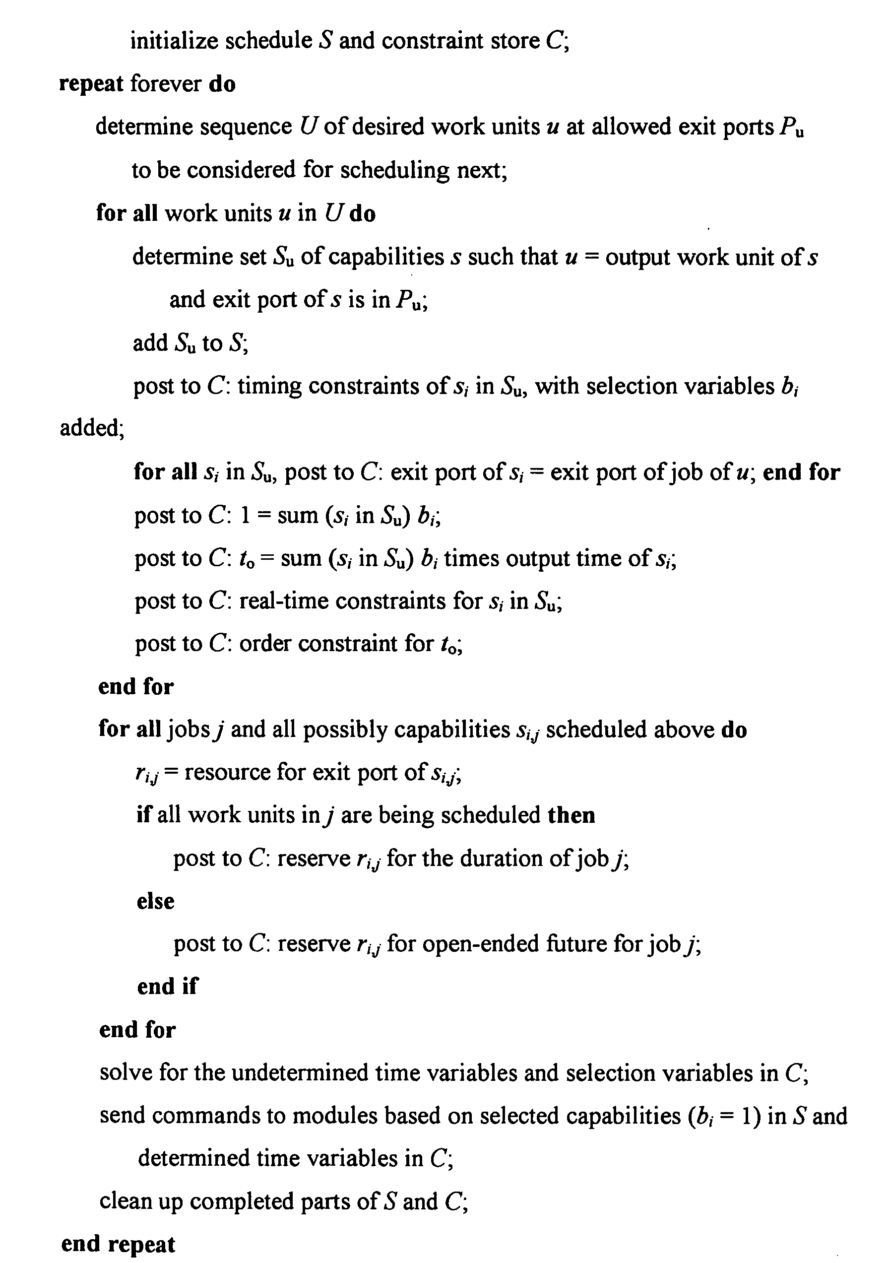
- the controller determines the work units to be planned and scheduled at step 230, based on the capability models provided by each module to be controlled and directed. This is an iterative step in which the controller incrementally reviews the jobs and their work units to select those work units to be planned and scheduled for the job next.
- the selected work units 235 are then transmitted to step 240, which plans the capabilities for the selected work units, taking into consideration the capability model for each module. This step is repeated for each work unit selected in the previous step, resulting in a set of planned capabilities 245.
- step 250 schedules the selected capabilities and provides a set of scheduled capabilities 255. These are in turn provided to step 260, at which the controller sends the commands 265 corresponding to the scheduled capabilities to the individual modules. This step is repeated for each scheduled capability.
- steps 230, 240, 250 and 260 has all model information available for selective usage during each step. For example step 240 may access feature constraints, step 250 may utilize timing constraints, and step 260 may utilize commands.
- a flow chart illustrates the planning function 300 of the controller.
- a work unit or job to be planned is selected at step 310 based on the input job description.
- the controller determines the capabilities needed to produce the work unit at step 320. In making this determination, the controller considers all possible system capabilities, from which alternative capabilities are selected.
- Timing constraints such as the amount of time required for each task within a job (e.g., the duration of a transport operation or a processing step), constraints on the intervals during which resources are occupied, and the reservation of resources during such intervals are modified by selection variables and posted to the controller at step 330.
- Selection variables are Boolean variables, one for each capability, that become either TRUE (the capability is selected) or FALSE (the capability is not selected). Selection variables are created automatically for each capability by the planning step.
- Constraints on the selection variables determine that, for example, only one of several alternative capabilities for the same output can be selected (i.e., only its selection variables can be TRUE).
- the modification of constraints is constraint-type-dependent. Allocation intervals in resource allocations, for example, are multiplied by the selection variables. The effect of these constraint modifications is that some constraints, such as a resource allocation, become only effective if the corresponding capability is being selected.
- the controller posts to memory constraints on selection variables and common modules to the constraint store at step 340. At step 350 real-time constraints and order constraints are posted to the controller.
- the output variables of all alternative capabilities are connected to a single time variable, which is then used in the precedence constraints.
- the job constraints reserve resources for a job and all possible exit ports of capabilities being considered for work units in the job. If only part of a job is being scheduled at this point, the selected resource is reserved for the open-ended future, and otherwise for the duration of the job.
- the sequence of steps presented is only one example embodiment for the method disclosed herein. It will be apparent to one skilled in the art that numerous alternate step sequences would produce a similar result.
- a flow chart illustrates the scheduling function 400 of the controller.
- the controller selects those capabilities to be scheduled, which may be all or a subset of the capabilities provided by the planning step.
- the controller reserves exit resources for planned capabilities within the same jobs at step 420. Since all work units of the same job are constrained to be delivered to the same final exit port, the resource connected to that same final exit port, corresponding for example to a finisher stack in a print engine, cannot be used by other jobs until the job is finished.
- the controller solves for timing and selection variables of planned capabilities. This can be accomplished using a number of constraint solving or constrained optimization techniques, which are known to those skilled in the art.
- commands are sent to the modules based on selected capabilities in the schedule and the determined time variables in the constraint store.
- code as used herein, or “program” as used herein, is any plurality of binary values or any executable, interpreted or compiled code which can be used by a computer or execution device to perform a task. This code or program can be written in any one of several known computer languages.
- a "computer”, as used herein, can mean any device which stores, processes, routes, manipulates, or performs like operation on data.
- selecting a work unit to be planned is based on an input job description.
- the system comprises selecting alternative capabilities from the reconfigurable production system modules.
- the selection variables may be created automatically for each capability.
- the selection variables may also comprise Boolean variables.
- said modified constraints comprise timing constraints.
- said modified constraints comprise the reservation of resources during intervals in which reconfigurable production system modules are occupied.
- posting timing and precedence constraints comprises connecting variables of all alternative capabilities to a single time variable.
- the system comprises means for acquiring at least one capability model from at least one machine module.
- said machine module comprises a print engine module.
- said machine module comprises an analysis module.
- said machine module comprises a packaging line module.
- said machine module comprises a manufacturing line module.
- the present invention also relates to a method for planning and scheduling the work flow for reconfigurable production systems, further comprising reserving a selected resource if only part of a job is being scheduled.
- said selected capabilities include a subset of capabilities needed to produce said work unit.
- said selected capabilities include all of the capabilities needed to produce said work unit.
- said capabilities comprise capability models for at least one machine module.
- said capabilities comprise feature constraints.
- said capabilities comprise timing constraints.
Landscapes
- Engineering & Computer Science (AREA)
- Business, Economics & Management (AREA)
- Human Resources & Organizations (AREA)
- Economics (AREA)
- Strategic Management (AREA)
- Entrepreneurship & Innovation (AREA)
- Operations Research (AREA)
- Physics & Mathematics (AREA)
- Educational Administration (AREA)
- Marketing (AREA)
- Development Economics (AREA)
- Quality & Reliability (AREA)
- Tourism & Hospitality (AREA)
- Game Theory and Decision Science (AREA)
- General Business, Economics & Management (AREA)
- General Physics & Mathematics (AREA)
- Theoretical Computer Science (AREA)
- Management, Administration, Business Operations System, And Electronic Commerce (AREA)
- General Factory Administration (AREA)
- Multi-Process Working Machines And Systems (AREA)
Abstract
Description
Reconfigurable production systems increasingly consist of multiple parallel, alternative modules that are connected through flexible paths and even loops. Consequently, such systems are expected to offer a multitude of alternative operations (or capabilities) to produce the same outputs. For example, a modular printing system may consist of several identical, parallel printers connected through flexible paper paths that feed to and collect from these printers. The system control software available for such systems today has as its heart a sophisticated scheduling component, but is not set up to make good use of such a reconfigurable, parallel production system. This is primarily due to the lack of a generic, powerful planning component which would select the optimal sequence of operations among the plurality of available operations.
A reconfigurable production system may be modeled as a graph of connected modules, with each module described by a model of its structure and its capabilities. The structure is primarily the interface through with work units enter and exit, such as entry and exit ports, plus any internally used resources. A capability is an operation that accepts work units at entry ports, processes them, and moves them to exit ports. (Entry and exit ports here refer to mechanical interfaces, such as slots or trays, as well as computer interfaces. A port may serve as both entry and exit port.) Operation of such a system has been modeled as a sequence of capability executions as work units move along valid paths in the graph from module to module.
An example for a reconfigurable production system is a modular printer, with modules such as feeders, mark engines, paper transports, inverters, etc. There, the work units are sheets and images. A simple paper transport module has an entry port, an exit port, and a single capability, to move a sheet of paper from its entry port to its exit port. An inverter module has one entry port, one exit port, and two capabilities, one to invert a sheet of paper and one to bypass the inversion mechanism. A mark engine transfer module has two entry ports (one for sheets and one for images), one exit port (for marked sheets), and one capability, to print the image onto the sheet. A sample resource in all of these modules is the space occupied by the sheet, which may only be occupied by one sheet at a time. Other examples of reconfigurable production systems are assembly lines, for example for the assembly or packing of computer parts, and automated analytic systems, such as blood sample analysis machines. In these different production systems, work units may be sheets of paper, electronic files, computer parts, semiconductor wafers, blood sample trays, any parts or composites of these, or other physical or electronic objects being processed by production systems. Transport mechanisms may be conveyor belts or robotic arms or any other devices or functions for moving work units.
Module capabilities may be composed to system capabilities by incrementally unifying work unit and time variables of output and input events at connected modules along valid paths in the system graph. For example, if a module's exit port is connected to another module's entry port, any capability producing work units for the first module's exit port potentially can be composed with any capability consuming work units from the second module's entry port. Unification of work unit and time variables ensures the consistency of attribute and time constraints.
A scheduler for such systems receives a stream of jobs, each consisting of a sequence of desired work units to be produced at some final exit port of the system. Each desired work unit is described by a work unit variable with attribute constraints. This is used to select a suitable system capability that can produce the desired work unit by unifying the desired work unit variable with the work unit variables of system capabilities producing work units for the desired exit port. As system capabilities for the desired work units in the jobs are found, their time and resource constraints are posted to the constraint store, and the constraints are solved in order to find time values for the various module capabilities producing the desired work units. The selected module capabilities plus the time values are then sent to the modules so that they can execute the corresponding operations at the designated times.
This approach to system control does not have a real planning component. Instead, the controller selects the first system capability it can find and schedules that capability. Also, the selection requires that the output, such as the finisher where the job should be delivered, be specified. These restrictions are acceptable in some production systems, such as a typical in-line printing system that has either few alternative system capabilities for the same kind of job, or where alternative system capabilities mainly differ in the feeders and finishers being used.
This approach proves unsatisfactory for systems with many alternative, parallel system capabilities. For example, printing systems with multiple identical or similar mark engine modules require a more intelligent selection of the capabilities to achieve optimal productivity and load balancing. This selection can in principle be done before the scheduling step based on rules (for example, a rule for alternating between all mark engines to attempt optimal load balancing). It is preferable, however, to integrate planning with scheduling, in which the selection of individual capabilities would depend on the selection and timing of other capabilities being planned and scheduled at the same time.
In accordance with another aspect of the present invention, there is provided a method for the automated planning and scheduling of the work flow for reconfigurable production systems having a plurality of modules. The modules of the reconfigurable production system have various capabilities. The method includes planning the work flow for the reconfigurable production system and also scheduling the work flow for the various modules.
In accordance with yet another aspect of the present invention, there is provided an article of manufacture in the form of a computer usable medium in which is embedded computer readable program code. When the program code is executed by a computer, method steps for planning and scheduling the work flow for computer controlled reconfigurable production systems are performed. These method steps take the form of planning the work flow for the production system and scheduling the work flow for a plurality of modules in the production system.
The selected
Claims (9)
- A computer controlled system for planning and scheduling the work flow for reconfigurable production systems having a plurality of modules with a plurality of alternative capabilities, the system comprising:a system controller;at least one planning function; andat least one scheduling function.
- The system for planning and scheduling reconfigurable production systems according to claim 1, wherein said planning function comprises;means for selecting at least one work unit to be planned;means for determining capabilities to produce said work unit;means for modifying constraints using selection variables;means for posting constraints on selection variables and common modules to memory;means for posting timing and precedence constraints to memory; andmeans for reserving a selected resource if only part of a job is being scheduled.
- The system for planning and scheduling reconfigurable production systems according to claim 2, wherein determining capabilities to produce said work unit further comprises considering all reconfigurable production system module capabilities.
- The system for planning and scheduling reconfigurable production systems according to claim 1, wherein said scheduling function comprises:means for selecting capabilities to be scheduled;means for reserving exit resources for planned capabilities; andmeans for solving for timing and selection variables.
- A method for planning and scheduling the work flow for reconfigurable production systems having a plurality of modules and including a system controller, comprising:planning the work flow for at least one reconfigurable production system; andscheduling the work flow for the plurality of modules in the reconfigurable production system.
- A method for planning and scheduling the work flow for reconfigurable production systems according to claim 5, wherein planning the work flow comprises:acquiring a description of work units to be produced;selecting at least one of said work units to be planned;determining the capabilities needed to produce said work unit;modifying constraints using selection variables;posting constraints on selection variables and common modules to memory; andposting timing and precedence constraints to memory.
- A method for planning and scheduling reconfigurable production systems having a plurality of modules according to claim 6, wherein determining the capabilities needed to produce said work unit comprises selecting alternative capabilities from the reconfigurable production system modules capabilities.
- A method for planning and scheduling the work flow for reconfigurable production systems according to claim 5, wherein scheduling the work flow for the plurality of modules in the reconfigurable production system comprises:selecting capabilities to be scheduled;reserving exit resources for planned capabilities within the same jobs; andsolving for timing and selection variables of planned capabilities.
- An article of manufacture comprising a computer usable medium having computer readable program code embodied in said medium which, when said program code is executed by a computer causes said computer to perform method steps for planning and scheduling reconfigurable systems having a plurality of modules, said method comprising:planning the work flow for at least one reconfigurable production system; andscheduling the work flow for the plurality of modules in the reconfigurable production system.
Applications Claiming Priority (2)
| Application Number | Priority Date | Filing Date | Title |
|---|---|---|---|
| US284561 | 2002-10-30 | ||
| US10/284,561 US7230736B2 (en) | 2002-10-30 | 2002-10-30 | Planning and scheduling reconfigurable systems with alternative capabilities |
Publications (2)
| Publication Number | Publication Date |
|---|---|
| EP1416408A2 true EP1416408A2 (en) | 2004-05-06 |
| EP1416408A3 EP1416408A3 (en) | 2004-05-26 |
Family
ID=32093527
Family Applications (1)
| Application Number | Title | Priority Date | Filing Date |
|---|---|---|---|
| EP03023990A Withdrawn EP1416408A3 (en) | 2002-10-30 | 2003-10-22 | Planning and scheduling reconfigurable systems with alternative capabilities |
Country Status (6)
| Country | Link |
|---|---|
| US (1) | US7230736B2 (en) |
| EP (1) | EP1416408A3 (en) |
| JP (1) | JP2004152293A (en) |
| BR (1) | BR0304780A (en) |
| CA (1) | CA2446796C (en) |
| MX (1) | MXPA03009917A (en) |
Cited By (2)
| Publication number | Priority date | Publication date | Assignee | Title |
|---|---|---|---|---|
| EP3686698A1 (en) * | 2019-01-24 | 2020-07-29 | ABB Schweiz AG | Automated creation of modular industrial plants |
| WO2021170211A1 (en) * | 2020-02-24 | 2021-09-02 | Abb Schweiz Ag | Computerized optimization of an engineered modular plant topology |
Families Citing this family (142)
| Publication number | Priority date | Publication date | Assignee | Title |
|---|---|---|---|---|
| US7226049B2 (en) | 2003-06-06 | 2007-06-05 | Xerox Corporation | Universal flexible plural printer to plural finisher sheet integration system |
| US7396012B2 (en) * | 2004-06-30 | 2008-07-08 | Xerox Corporation | Flexible paper path using multidirectional path modules |
| US7206532B2 (en) * | 2004-08-13 | 2007-04-17 | Xerox Corporation | Multiple object sources controlled and/or selected based on a common sensor |
| US7188929B2 (en) * | 2004-08-13 | 2007-03-13 | Xerox Corporation | Parallel printing architecture with containerized image marking engines |
| US7542059B2 (en) * | 2006-03-17 | 2009-06-02 | Xerox Corporation | Page scheduling for printing architectures |
| US7493055B2 (en) * | 2006-03-17 | 2009-02-17 | Xerox Corporation | Fault isolation of visible defects with manual module shutdown options |
| US7024152B2 (en) * | 2004-08-23 | 2006-04-04 | Xerox Corporation | Printing system with horizontal highway and single pass duplex |
| US7136616B2 (en) * | 2004-08-23 | 2006-11-14 | Xerox Corporation | Parallel printing architecture using image marking engine modules |
| US7742185B2 (en) | 2004-08-23 | 2010-06-22 | Xerox Corporation | Print sequence scheduling for reliability |
| US7308218B2 (en) * | 2005-06-14 | 2007-12-11 | Xerox Corporation | Warm-up of multiple integrated marking engines |
| US7649645B2 (en) | 2005-06-21 | 2010-01-19 | Xerox Corporation | Method of ordering job queue of marking systems |
| US7123873B2 (en) * | 2004-08-23 | 2006-10-17 | Xerox Corporation | Printing system with inverter disposed for media velocity buffering and registration |
| US9250967B2 (en) * | 2004-08-23 | 2016-02-02 | Palo Alto Research Center Incorporated | Model-based planning with multi-capacity resources |
| US7787138B2 (en) * | 2005-05-25 | 2010-08-31 | Xerox Corporation | Scheduling system |
| US7245838B2 (en) * | 2005-06-20 | 2007-07-17 | Xerox Corporation | Printing platform |
| US7224913B2 (en) * | 2005-05-05 | 2007-05-29 | Xerox Corporation | Printing system and scheduling method |
| US7619769B2 (en) * | 2005-05-25 | 2009-11-17 | Xerox Corporation | Printing system |
| US8407077B2 (en) * | 2006-02-28 | 2013-03-26 | Palo Alto Research Center Incorporated | System and method for manufacturing system design and shop scheduling using network flow modeling |
| US7302199B2 (en) * | 2005-05-25 | 2007-11-27 | Xerox Corporation | Document processing system and methods for reducing stress therein |
| US20070002085A1 (en) * | 2005-06-30 | 2007-01-04 | Xerox Corporation | High availability printing systems |
| US7336920B2 (en) * | 2004-09-28 | 2008-02-26 | Xerox Corporation | Printing system |
| US7324779B2 (en) * | 2004-09-28 | 2008-01-29 | Xerox Corporation | Printing system with primary and secondary fusing devices |
| US7751072B2 (en) * | 2004-09-29 | 2010-07-06 | Xerox Corporation | Automated modification of a marking engine in a printing system |
| US7162172B2 (en) * | 2004-11-30 | 2007-01-09 | Xerox Corporation | Semi-automatic image quality adjustment for multiple marking engine systems |
| US7310108B2 (en) * | 2004-11-30 | 2007-12-18 | Xerox Corporation | Printing system |
| US7412180B2 (en) * | 2004-11-30 | 2008-08-12 | Xerox Corporation | Glossing system for use in a printing system |
| US7245856B2 (en) * | 2004-11-30 | 2007-07-17 | Xerox Corporation | Systems and methods for reducing image registration errors |
| US20060114497A1 (en) * | 2004-11-30 | 2006-06-01 | Xerox Corporation | Printing system |
| US7791751B2 (en) * | 2004-11-30 | 2010-09-07 | Palo Alto Research Corporation | Printing systems |
| US7283762B2 (en) | 2004-11-30 | 2007-10-16 | Xerox Corporation | Glossing system for use in a printing architecture |
| US7305194B2 (en) * | 2004-11-30 | 2007-12-04 | Xerox Corporation | Xerographic device streak failure recovery |
| JP4450205B2 (en) * | 2004-12-24 | 2010-04-14 | ブラザー工業株式会社 | Inkjet recording device |
| US7540484B2 (en) * | 2005-02-02 | 2009-06-02 | Xerox Corporation | System of opposing alternate higher speed sheet feeding from the same sheet stack |
| US7226158B2 (en) * | 2005-02-04 | 2007-06-05 | Xerox Corporation | Printing systems |
| US7791741B2 (en) * | 2005-04-08 | 2010-09-07 | Palo Alto Research Center Incorporated | On-the-fly state synchronization in a distributed system |
| US8081329B2 (en) | 2005-06-24 | 2011-12-20 | Xerox Corporation | Mixed output print control method and system |
| US8819103B2 (en) * | 2005-04-08 | 2014-08-26 | Palo Alto Research Center, Incorporated | Communication in a distributed system |
| US7873962B2 (en) * | 2005-04-08 | 2011-01-18 | Xerox Corporation | Distributed control systems and methods that selectively activate respective coordinators for respective tasks |
| US8014024B2 (en) * | 2005-03-02 | 2011-09-06 | Xerox Corporation | Gray balance for a printing system of multiple marking engines |
| US7697151B2 (en) | 2005-03-25 | 2010-04-13 | Xerox Corporation | Image quality control method and apparatus for multiple marking engine systems |
| US7416185B2 (en) * | 2005-03-25 | 2008-08-26 | Xerox Corporation | Inverter with return/bypass paper path |
| US7258340B2 (en) * | 2005-03-25 | 2007-08-21 | Xerox Corporation | Sheet registration within a media inverter |
| US7206536B2 (en) * | 2005-03-29 | 2007-04-17 | Xerox Corporation | Printing system with custom marking module and method of printing |
| US7444108B2 (en) * | 2005-03-31 | 2008-10-28 | Xerox Corporation | Parallel printing architecture with parallel horizontal printing modules |
| US7272334B2 (en) * | 2005-03-31 | 2007-09-18 | Xerox Corporation | Image on paper registration alignment |
| US7305198B2 (en) * | 2005-03-31 | 2007-12-04 | Xerox Corporation | Printing system |
| US7245844B2 (en) * | 2005-03-31 | 2007-07-17 | Xerox Corporation | Printing system |
| US7706007B2 (en) * | 2005-04-08 | 2010-04-27 | Palo Alto Research Center Incorporated | Synchronization in a distributed system |
| US7566053B2 (en) * | 2005-04-19 | 2009-07-28 | Xerox Corporation | Media transport system |
| US7593130B2 (en) * | 2005-04-20 | 2009-09-22 | Xerox Corporation | Printing systems |
| US20060244980A1 (en) * | 2005-04-27 | 2006-11-02 | Xerox Corporation | Image quality adjustment method and system |
| US20060268287A1 (en) * | 2005-05-25 | 2006-11-30 | Xerox Corporation | Automated promotion of monochrome jobs for HLC production printers |
| US7486416B2 (en) * | 2005-06-02 | 2009-02-03 | Xerox Corporation | Inter-separation decorrelator |
| US8004729B2 (en) * | 2005-06-07 | 2011-08-23 | Xerox Corporation | Low cost adjustment method for printing systems |
| US7387297B2 (en) * | 2005-06-24 | 2008-06-17 | Xerox Corporation | Printing system sheet feeder using rear and front nudger rolls |
| US7310493B2 (en) * | 2005-06-24 | 2007-12-18 | Xerox Corporation | Multi-unit glossing subsystem for a printing device |
| US7451697B2 (en) * | 2005-06-24 | 2008-11-18 | Xerox Corporation | Printing system |
| US7433627B2 (en) * | 2005-06-28 | 2008-10-07 | Xerox Corporation | Addressable irradiation of images |
| US8203768B2 (en) * | 2005-06-30 | 2012-06-19 | Xerox Corporaiton | Method and system for processing scanned patches for use in imaging device calibration |
| US8259369B2 (en) | 2005-06-30 | 2012-09-04 | Xerox Corporation | Color characterization or calibration targets with noise-dependent patch size or number |
| JP4345721B2 (en) * | 2005-07-14 | 2009-10-14 | コニカミノルタビジネステクノロジーズ株式会社 | Management system |
| US7647018B2 (en) * | 2005-07-26 | 2010-01-12 | Xerox Corporation | Printing system |
| US7496412B2 (en) | 2005-07-29 | 2009-02-24 | Xerox Corporation | Control method using dynamic latitude allocation and setpoint modification, system using the control method, and computer readable recording media containing the control method |
| US7466940B2 (en) * | 2005-08-22 | 2008-12-16 | Xerox Corporation | Modular marking architecture for wide media printing platform |
| US7474861B2 (en) * | 2005-08-30 | 2009-01-06 | Xerox Corporation | Consumable selection in a printing system |
| US7911652B2 (en) * | 2005-09-08 | 2011-03-22 | Xerox Corporation | Methods and systems for determining banding compensation parameters in printing systems |
| US7430380B2 (en) * | 2005-09-23 | 2008-09-30 | Xerox Corporation | Printing system |
| US7495799B2 (en) * | 2005-09-23 | 2009-02-24 | Xerox Corporation | Maximum gamut strategy for the printing systems |
| US7444088B2 (en) * | 2005-10-11 | 2008-10-28 | Xerox Corporation | Printing system with balanced consumable usage |
| US7811017B2 (en) * | 2005-10-12 | 2010-10-12 | Xerox Corporation | Media path crossover for printing system |
| US8711435B2 (en) * | 2005-11-04 | 2014-04-29 | Xerox Corporation | Method for correcting integrating cavity effect for calibration and/or characterization targets |
| US7719716B2 (en) * | 2005-11-04 | 2010-05-18 | Xerox Corporation | Scanner characterization for printer calibration |
| US7660460B2 (en) * | 2005-11-15 | 2010-02-09 | Xerox Corporation | Gamut selection in multi-engine systems |
| US7280771B2 (en) * | 2005-11-23 | 2007-10-09 | Xerox Corporation | Media pass through mode for multi-engine system |
| US7519314B2 (en) * | 2005-11-28 | 2009-04-14 | Xerox Corporation | Multiple IOT photoreceptor belt seam synchronization |
| US7922288B2 (en) * | 2005-11-30 | 2011-04-12 | Xerox Corporation | Printing system |
| US7575232B2 (en) | 2005-11-30 | 2009-08-18 | Xerox Corporation | Media path crossover clearance for printing system |
| US7706737B2 (en) | 2005-11-30 | 2010-04-27 | Xerox Corporation | Mixed output printing system |
| US7636543B2 (en) * | 2005-11-30 | 2009-12-22 | Xerox Corporation | Radial merge module for printing system |
| JP2007164422A (en) * | 2005-12-13 | 2007-06-28 | Canon Inc | Information processing apparatus, information processing method, and information processing program |
| US7912416B2 (en) | 2005-12-20 | 2011-03-22 | Xerox Corporation | Printing system architecture with center cross-over and interposer by-pass path |
| US7756428B2 (en) | 2005-12-21 | 2010-07-13 | Xerox Corp. | Media path diagnostics with hyper module elements |
| US7826090B2 (en) * | 2005-12-21 | 2010-11-02 | Xerox Corporation | Method and apparatus for multiple printer calibration using compromise aim |
| US8102564B2 (en) * | 2005-12-22 | 2012-01-24 | Xerox Corporation | Method and system for color correction using both spatial correction and printer calibration techniques |
| US7624981B2 (en) * | 2005-12-23 | 2009-12-01 | Palo Alto Research Center Incorporated | Universal variable pitch interface interconnecting fixed pitch sheet processing machines |
| US7746524B2 (en) * | 2005-12-23 | 2010-06-29 | Xerox Corporation | Bi-directional inverter printing apparatus and method |
| US7963518B2 (en) | 2006-01-13 | 2011-06-21 | Xerox Corporation | Printing system inverter apparatus and method |
| US8477333B2 (en) * | 2006-01-27 | 2013-07-02 | Xerox Corporation | Printing system and bottleneck obviation through print job sequencing |
| US7630669B2 (en) * | 2006-02-08 | 2009-12-08 | Xerox Corporation | Multi-development system print engine |
| US7672006B2 (en) * | 2006-02-22 | 2010-03-02 | Xerox Corporation | Multi-marking engine printing platform |
| US8194262B2 (en) * | 2006-02-27 | 2012-06-05 | Xerox Corporation | System for masking print defects |
| US7965397B2 (en) * | 2006-04-06 | 2011-06-21 | Xerox Corporation | Systems and methods to measure banding print defects |
| US8330965B2 (en) | 2006-04-13 | 2012-12-11 | Xerox Corporation | Marking engine selection |
| US7681883B2 (en) * | 2006-05-04 | 2010-03-23 | Xerox Corporation | Diverter assembly, printing system and method |
| US7382993B2 (en) * | 2006-05-12 | 2008-06-03 | Xerox Corporation | Process controls methods and apparatuses for improved image consistency |
| US7800777B2 (en) * | 2006-05-12 | 2010-09-21 | Xerox Corporation | Automatic image quality control of marking processes |
| US7679631B2 (en) | 2006-05-12 | 2010-03-16 | Xerox Corporation | Toner supply arrangement |
| US7865125B2 (en) * | 2006-06-23 | 2011-01-04 | Xerox Corporation | Continuous feed printing system |
| US7856191B2 (en) * | 2006-07-06 | 2010-12-21 | Xerox Corporation | Power regulator of multiple integrated marking engines |
| US7924443B2 (en) * | 2006-07-13 | 2011-04-12 | Xerox Corporation | Parallel printing system |
| US8607102B2 (en) * | 2006-09-15 | 2013-12-10 | Palo Alto Research Center Incorporated | Fault management for a printing system |
| US7766327B2 (en) * | 2006-09-27 | 2010-08-03 | Xerox Corporation | Sheet buffering system |
| US7857309B2 (en) * | 2006-10-31 | 2010-12-28 | Xerox Corporation | Shaft driving apparatus |
| US7819401B2 (en) | 2006-11-09 | 2010-10-26 | Xerox Corporation | Print media rotary transport apparatus and method |
| US8159713B2 (en) * | 2006-12-11 | 2012-04-17 | Xerox Corporation | Data binding in multiple marking engine printing systems |
| US7969624B2 (en) * | 2006-12-11 | 2011-06-28 | Xerox Corporation | Method and system for identifying optimal media for calibration and control |
| US7945346B2 (en) * | 2006-12-14 | 2011-05-17 | Palo Alto Research Center Incorporated | Module identification method and system for path connectivity in modular systems |
| US8100523B2 (en) * | 2006-12-19 | 2012-01-24 | Xerox Corporation | Bidirectional media sheet transport apparatus |
| US8145335B2 (en) | 2006-12-19 | 2012-03-27 | Palo Alto Research Center Incorporated | Exception handling |
| US7559549B2 (en) | 2006-12-21 | 2009-07-14 | Xerox Corporation | Media feeder feed rate |
| US8693021B2 (en) * | 2007-01-23 | 2014-04-08 | Xerox Corporation | Preemptive redirection in printing systems |
| US7934825B2 (en) * | 2007-02-20 | 2011-05-03 | Xerox Corporation | Efficient cross-stream printing system |
| US7676191B2 (en) | 2007-03-05 | 2010-03-09 | Xerox Corporation | Method of duplex printing on sheet media |
| US7894107B2 (en) * | 2007-04-27 | 2011-02-22 | Xerox Corporation | Optical scanner with non-redundant overwriting |
| US20080268839A1 (en) * | 2007-04-27 | 2008-10-30 | Ayers John I | Reducing a number of registration termination massages in a network for cellular devices |
| US8253958B2 (en) * | 2007-04-30 | 2012-08-28 | Xerox Corporation | Scheduling system |
| US8169657B2 (en) * | 2007-05-09 | 2012-05-01 | Xerox Corporation | Registration method using sensed image marks and digital realignment |
| US7590464B2 (en) * | 2007-05-29 | 2009-09-15 | Palo Alto Research Center Incorporated | System and method for on-line planning utilizing multiple planning queues |
| US7689311B2 (en) * | 2007-05-29 | 2010-03-30 | Palo Alto Research Center Incorporated | Model-based planning using query-based component executable instructions |
| US7925366B2 (en) * | 2007-05-29 | 2011-04-12 | Xerox Corporation | System and method for real-time system control using precomputed plans |
| US8203750B2 (en) | 2007-08-01 | 2012-06-19 | Xerox Corporation | Color job reprint set-up for a printing system |
| US7697166B2 (en) * | 2007-08-03 | 2010-04-13 | Xerox Corporation | Color job output matching for a printing system |
| US7590501B2 (en) | 2007-08-28 | 2009-09-15 | Xerox Corporation | Scanner calibration robust to lamp warm-up |
| US8612991B2 (en) * | 2007-12-18 | 2013-12-17 | International Business Machines Corporation | Dynamic critical-path recalculation facility |
| US8151267B2 (en) * | 2008-04-08 | 2012-04-03 | Xerox Corporation | Printing system scheduler methods and systems |
| US8077358B2 (en) * | 2008-04-24 | 2011-12-13 | Xerox Corporation | Systems and methods for implementing use of customer documents in maintaining image quality (IQ)/image quality consistency (IQC) of printing devices |
| US8219437B2 (en) | 2008-07-10 | 2012-07-10 | Palo Alto Research Center Incorporated | Methods and systems for constructing production plans |
| US8145334B2 (en) * | 2008-07-10 | 2012-03-27 | Palo Alto Research Center Incorporated | Methods and systems for active diagnosis through logic-based planning |
| US7937175B2 (en) * | 2008-07-10 | 2011-05-03 | Palo Alto Research Center Incorporated | Methods and systems for pervasive diagnostics |
| US8165705B2 (en) * | 2008-07-10 | 2012-04-24 | Palo Alto Research Center Incorporated | Methods and systems for continuously estimating persistent and intermittent failure probabilities for production resources |
| US8266092B2 (en) * | 2008-07-10 | 2012-09-11 | Palo Alto Research Center Incorporated | Methods and systems for target value path identification |
| US8612050B2 (en) * | 2008-07-29 | 2013-12-17 | Palo Alto Research Center Incorporated | Intelligent product feed system and method |
| US8169626B2 (en) | 2008-08-29 | 2012-05-01 | Xerox Corporation | Using buffers to support uncertainties in marking engine execution |
| US8989879B2 (en) * | 2008-09-27 | 2015-03-24 | Jda Software Group, Inc. | System and method for a demand driven lean production control system |
| US8978045B2 (en) * | 2009-03-06 | 2015-03-10 | Applied Materials, Inc. | Per-station start time constraint |
| US8359110B2 (en) * | 2009-03-23 | 2013-01-22 | Kuhn Lukas D | Methods and systems for fault diagnosis in observation rich systems |
| US7976012B2 (en) | 2009-04-28 | 2011-07-12 | Xerox Corporation | Paper feeder for modular printers |
| US9373960B2 (en) * | 2013-03-13 | 2016-06-21 | Oracle International Corporation | Computerized system and method for distributed energy resource scheduling |
| EP3616207A1 (en) * | 2017-04-28 | 2020-03-04 | GE Healthcare Bio-Sciences AB | Method and system for creating reconfigurable bio-processing workflows |
| US11987783B2 (en) | 2017-04-28 | 2024-05-21 | Cytiva Sweden Ab | System and method for wirelessly powering a sensor in a bio-processing environment |
| WO2018197274A1 (en) | 2017-04-28 | 2018-11-01 | Ge Healthcare Bio-Sciences Ab | System and method for enabling a single use wireless sensor by optimizing electrical power |
| US12585501B2 (en) | 2022-02-21 | 2026-03-24 | Bank Of America Corporation | Machine-learning (ML)-based resource utilization prediction and management engine |
Family Cites Families (10)
| Publication number | Priority date | Publication date | Assignee | Title |
|---|---|---|---|---|
| US5093794A (en) * | 1989-08-22 | 1992-03-03 | United Technologies Corporation | Job scheduling system |
| US5095342A (en) * | 1990-09-28 | 1992-03-10 | Xerox Corporation | Methods for sheet scheduling in an imaging system having an endless duplex paper path loop |
| JP2512842B2 (en) * | 1991-08-27 | 1996-07-03 | 松下電工株式会社 | Production planning method |
| US5159395A (en) * | 1991-08-29 | 1992-10-27 | Xerox Corporation | Method of scheduling copy sheets in a dual mode duplex printing system |
| US5557367A (en) * | 1995-03-27 | 1996-09-17 | Xerox Corporation | Method and apparatus for optimizing scheduling in imaging devices |
| US5696893A (en) * | 1995-06-07 | 1997-12-09 | Xerox Corporation | System for generically describing and scheduling operation of modular printing machine |
| US5631740A (en) * | 1995-11-28 | 1997-05-20 | Xerox Corporation | Transducers with constraints model for print scheduling |
| JPH11282909A (en) * | 1998-03-26 | 1999-10-15 | Toshiba Corp | Production scheduling method and apparatus |
| US6546364B1 (en) * | 1998-12-18 | 2003-04-08 | Impresse Corporation | Method and apparatus for creating adaptive workflows |
| US7283971B1 (en) | 2000-09-06 | 2007-10-16 | Masterlink Corporation | System and method for managing mobile workers |
-
2002
- 2002-10-30 US US10/284,561 patent/US7230736B2/en not_active Expired - Lifetime
-
2003
- 2003-10-22 EP EP03023990A patent/EP1416408A3/en not_active Withdrawn
- 2003-10-24 CA CA2446796A patent/CA2446796C/en not_active Expired - Fee Related
- 2003-10-27 JP JP2003366030A patent/JP2004152293A/en active Pending
- 2003-10-28 BR BR0304780-6A patent/BR0304780A/en not_active Application Discontinuation
- 2003-10-29 MX MXPA03009917A patent/MXPA03009917A/en not_active Application Discontinuation
Cited By (4)
| Publication number | Priority date | Publication date | Assignee | Title |
|---|---|---|---|---|
| EP3686698A1 (en) * | 2019-01-24 | 2020-07-29 | ABB Schweiz AG | Automated creation of modular industrial plants |
| WO2020152025A1 (en) * | 2019-01-24 | 2020-07-30 | Abb Schweiz Ag | Automated creation of modular industrial plants |
| WO2021170211A1 (en) * | 2020-02-24 | 2021-09-02 | Abb Schweiz Ag | Computerized optimization of an engineered modular plant topology |
| US12379715B2 (en) | 2020-02-24 | 2025-08-05 | Abb Schweiz Ag | Computerized optimization of an engineered modular plant topology |
Also Published As
| Publication number | Publication date |
|---|---|
| MXPA03009917A (en) | 2005-04-19 |
| BR0304780A (en) | 2004-08-31 |
| CA2446796C (en) | 2011-07-12 |
| US20040085562A1 (en) | 2004-05-06 |
| JP2004152293A (en) | 2004-05-27 |
| EP1416408A3 (en) | 2004-05-26 |
| CA2446796A1 (en) | 2004-04-30 |
| US7230736B2 (en) | 2007-06-12 |
Similar Documents
| Publication | Publication Date | Title |
|---|---|---|
| US7230736B2 (en) | Planning and scheduling reconfigurable systems with alternative capabilities | |
| US8315898B2 (en) | Planning and scheduling reconfigurable systems around off-line resources | |
| CA2447067C (en) | Planning and scheduling reconfigurable systems with regular and diagnostic jobs | |
| US6895292B2 (en) | Predictive and preemptive planning and scheduling for different job priorities system and method | |
| EP0747793B1 (en) | Modular print engine scheduling method | |
| US8005561B2 (en) | Method for self-synchronization of modular production systems | |
| EP1480144A1 (en) | Planning and scheduling for failure recovery system and method | |
| EP0747790A2 (en) | Automatic print engine software configuration system | |
| US5668942A (en) | Generic system for describing and using resources for print engine scheduling | |
| US6898475B1 (en) | System and method utilizing temporal constraints to coordinate multiple planning sessions | |
| JP2008260286A (en) | Method for determining print-engine capability | |
| US7451132B2 (en) | System and method for production planning utilizing on-line state-space planning | |
| Riedelbauch et al. | Visual programming of robot tasks with product and process variety | |
| Agnetis et al. | Concurrent operations assignment and sequencing for particular assembly problems in flow lines | |
| Shah et al. | New modeling and performance evaluation of tool sharing control in FMS using colored Petri nets | |
| Biegel et al. | Expert systems can do job shop scheduling: an exploration and a proposal | |
| Qiu et al. | A process-driven computing model for reconfigurable semiconductor manufacturing |
Legal Events
| Date | Code | Title | Description |
|---|---|---|---|
| PUAI | Public reference made under article 153(3) epc to a published international application that has entered the european phase |
Free format text: ORIGINAL CODE: 0009012 |
|
| PUAL | Search report despatched |
Free format text: ORIGINAL CODE: 0009013 |
|
| AK | Designated contracting states |
Kind code of ref document: A2 Designated state(s): AT BE BG CH CY CZ DE DK EE ES FI FR GB GR HU IE IT LI LU MC NL PT RO SE SI SK TR |
|
| AX | Request for extension of the european patent |
Extension state: AL LT LV MK |
|
| AK | Designated contracting states |
Kind code of ref document: A3 Designated state(s): AT BE BG CH CY CZ DE DK EE ES FI FR GB GR HU IE IT LI LU MC NL PT RO SE SI SK TR |
|
| AX | Request for extension of the european patent |
Extension state: AL LT LV MK |
|
| 17P | Request for examination filed |
Effective date: 20041126 |
|
| AKX | Designation fees paid |
Designated state(s): DE FR GB |
|
| 17Q | First examination report despatched |
Effective date: 20050324 |
|
| APBN | Date of receipt of notice of appeal recorded |
Free format text: ORIGINAL CODE: EPIDOSNNOA2E |
|
| APBR | Date of receipt of statement of grounds of appeal recorded |
Free format text: ORIGINAL CODE: EPIDOSNNOA3E |
|
| APAF | Appeal reference modified |
Free format text: ORIGINAL CODE: EPIDOSCREFNE |
|
| APBX | Invitation to file observations in appeal sent |
Free format text: ORIGINAL CODE: EPIDOSNOBA2E |
|
| APBT | Appeal procedure closed |
Free format text: ORIGINAL CODE: EPIDOSNNOA9E |
|
| STAA | Information on the status of an ep patent application or granted ep patent |
Free format text: STATUS: THE APPLICATION IS DEEMED TO BE WITHDRAWN |
|
| 18D | Application deemed to be withdrawn |
Effective date: 20140121 |
|
| REG | Reference to a national code |
Ref country code: DE Ref legal event code: R079 Free format text: PREVIOUS MAIN CLASS: G06F0017600000 Ipc: G06Q0010000000 Effective date: 20140724 |