EP1416348A1 - Methodology for temporal fault event isolation and identification - Google Patents
Methodology for temporal fault event isolation and identification Download PDFInfo
- Publication number
- EP1416348A1 EP1416348A1 EP03256921A EP03256921A EP1416348A1 EP 1416348 A1 EP1416348 A1 EP 1416348A1 EP 03256921 A EP03256921 A EP 03256921A EP 03256921 A EP03256921 A EP 03256921A EP 1416348 A1 EP1416348 A1 EP 1416348A1
- Authority
- EP
- European Patent Office
- Prior art keywords
- event
- parameter measurements
- fault
- calculating
- vectors
- Prior art date
- Legal status (The legal status is an assumption and is not a legal conclusion. Google has not performed a legal analysis and makes no representation as to the accuracy of the status listed.)
- Granted
Links
- 238000000034 method Methods 0.000 title claims abstract description 49
- 238000002955 isolation Methods 0.000 title claims abstract description 25
- 230000002123 temporal effect Effects 0.000 title description 7
- 238000005259 measurement Methods 0.000 claims abstract description 69
- 239000013598 vector Substances 0.000 claims abstract description 57
- 238000004088 simulation Methods 0.000 claims abstract description 3
- 238000012423 maintenance Methods 0.000 claims abstract 4
- 238000012545 processing Methods 0.000 claims description 9
- 238000012958 reprocessing Methods 0.000 claims description 7
- 238000012417 linear regression Methods 0.000 claims description 5
- 238000004364 calculation method Methods 0.000 claims description 4
- 238000007619 statistical method Methods 0.000 claims description 3
- 238000001514 detection method Methods 0.000 description 16
- 230000006866 deterioration Effects 0.000 description 13
- 238000004422 calculation algorithm Methods 0.000 description 6
- 238000010586 diagram Methods 0.000 description 6
- 230000007774 longterm Effects 0.000 description 6
- 239000011159 matrix material Substances 0.000 description 3
- 238000013528 artificial neural network Methods 0.000 description 2
- 230000000977 initiatory effect Effects 0.000 description 2
- 238000012986 modification Methods 0.000 description 2
- 230000004048 modification Effects 0.000 description 2
- 238000012935 Averaging Methods 0.000 description 1
- 230000015556 catabolic process Effects 0.000 description 1
- 238000006731 degradation reaction Methods 0.000 description 1
- 238000013461 design Methods 0.000 description 1
- 230000002542 deteriorative effect Effects 0.000 description 1
- 230000000694 effects Effects 0.000 description 1
- 238000011156 evaluation Methods 0.000 description 1
- 239000000446 fuel Substances 0.000 description 1
- 230000007257 malfunction Effects 0.000 description 1
- 230000000116 mitigating effect Effects 0.000 description 1
- 238000012544 monitoring process Methods 0.000 description 1
- 238000005096 rolling process Methods 0.000 description 1
- 238000012360 testing method Methods 0.000 description 1
Images

Classifications
-
- G—PHYSICS
- G05—CONTROLLING; REGULATING
- G05B—CONTROL OR REGULATING SYSTEMS IN GENERAL; FUNCTIONAL ELEMENTS OF SUCH SYSTEMS; MONITORING OR TESTING ARRANGEMENTS FOR SUCH SYSTEMS OR ELEMENTS
- G05B23/00—Testing or monitoring of control systems or parts thereof
- G05B23/02—Electric testing or monitoring
- G05B23/0205—Electric testing or monitoring by means of a monitoring system capable of detecting and responding to faults
- G05B23/0259—Electric testing or monitoring by means of a monitoring system capable of detecting and responding to faults characterized by the response to fault detection
- G05B23/0275—Fault isolation and identification, e.g. classify fault; estimate cause or root of failure
Definitions
- the present invention relates to a method for isolating and identifying temporal fault events. More specifically, the present invention relates to a method of performing single fault isolation and detection in engine systems, and, if warranted, double fault isolation and detection.
- gas turbine performance diagnostics The goal of gas turbine performance diagnostics is to accurately detect, isolate and assess the changes in engine module performance, engine system malfunctions, and instrumentation problems from knowledge of measured parameters taken along the engine's gas path. Discernable shifts in engine speeds, temperatures, pressures, fuel flow, etc., provide the requisite information for determining the underlying shift in engine operation from a presumed reference (nominal) state.
- the aforementioned engine performance changes can manifest themselves in one of two categories: a) gradual (long-term) deterioration or b) rapid (short-term) deterioration.
- a method of fault event identification which comprises the steps of receiving a plurality of parameter measurements, performing single fault isolation to establish one of the plurality of parameter measurements as an event start, one of the plurality of parameter measurements as an event detect, and one of the parameter measurements as an event end wherein a latency period extends from the event start to the event detect and a blackout period extends from the event start to the event end, performing multiple fault isolation to establish a first trend line for the plurality of parameter measurements prior to the blackout period and after the blackout period, reprocessing the parameter measurements in the latency period, processing the parameter measurements in the blackout period, introducing a set of model Influence Coefficients (IC), interpolated at the power setting being analyzed, calculating a plurality of single fault vectors, calculating an estimate for each of the single fault vectors, calculating a normalized error for each of the plurality of single fault vectors, calculating a polarized error term for each of the plurality of single fault vectors, and selecting the single fault
- IC model Influence
- a method of fault event identification comprises the steps of receiving a plurality of parameter measurements, performing single fault isolation to establish one of the plurality of parameter measurements as an event start, one of the plurality of parameter measurements as an event detect, and one of the parameter measurements as an event end wherein a latency period extends from the event start to the event detect and a blackout period extends from the event start to the event end, performing multiple fault isolation to establish a first trend line for the plurality of parameter measurements prior to the blackout period and after the blackout period, reprocessing the parameter measurements in the latency period, processing the parameter measurements in the blackout period, calculating a matrix of Influence Coefficients (IC) from an aero-thermal model simulation of the engine, calculating a plurality of single fault vectors, calculating an estimate for each of the single fault vectors, calculating a normalized error for each of the plurality of single fault vectors, calculating a polarized error term for each of the plurality of single fault vectors, and determining if double
- the present invention is drawn to isolating short-term deterioration in the instance where a fault event has been detected in a system. While described in the following with exemplary reference to gas path parameters in an engine, the present invention is broadly drawn to encompass any system comprised of a plurality of interoperating subsystems or modules which may be measured and quantified during operation.
- the problem of detection is one of recognizing a step or rate change in a gas path parameter or a collection of parameters.
- Methods to detect an engine performance event, or fault event, by virtue of detecting that a shift (or rapid change) in a set of measured engine parameters has occurred at some discrete time k are well known in the art.
- MFI Multiple Fault Isolation
- SFI Single Fault Isolation
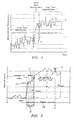
- Measurement parameter ⁇ is preferably a percent or other measured change between a current measurement and a reference parameter value representing a nominal baseline condition. Note that for both long term 11 deterioration periods there is computed a trend line 15. Trend lines 15 are preferably best fit lines derived from linear regression that capture the gradual rate of deterioration in a parameter's measurements, but can also be represented by moving or exponential averages.
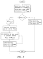
- processing is taking place at each discrete time point.
- the default isolation process is taken to be the MFI (Multiple Fault Isolation), wherein performance changes (relative to reference) in the modules and sensors being monitored are inferred from the collection of measurement parameter changes (i.e., As from reference) at time k.
- MFI Multiple Fault Isolation
- MFI MFI based methods
- Kalman Filters to methods employing Artificial Neural Networks.
- preferable SFI methods include, but are not limited to, statistical methods and methods incorporating Artificial Neural Networks.
- the algorithm of the present invention possesses a plurality of properties as will be described more fully below.
- the algorithm allows for and accommodates the natural latency in the detection of a temporal event thereby mitigating the effects of concurrent MFI processing.
- the algorithm automatically accommodates single and double fault events.
- the algorithm automatically accommodates any measurement set or subset and it accommodates any set of pre-defined faults.
- the SFI operates on temporal changes, i.e. measurement parameter ⁇ s, as indicated in Figure 2. This provides a performance ⁇ from the initiation of the event.
- the reference in this case is whatever the performance was at discrete time k start -1. This is what distinguishes a short-term (event) deterioration from long-term (gradual) deterioration.
- the Measurement A Averages are preferably computed by using exponential averages which are recursive and require minimal memory. Like a rolling average, this form of averaging also tracks parameter trends over time. They are computed as follows: where the (pre-chosen) constant ⁇ , provides the level of weighting for the past average and current data point.
- the ⁇ k calculations are made relative to the average level just prior to the event initiation, i.e. discrete time k start - 1. The calculation applies to the entire Blackout Period 29, but differs for the reprocessed Latency Period 27. In the Latency Period 27, a linear time regression is performed and the ⁇ k values are computed as the difference between this regression line and the average level (prior to the event) as outlined below.
- n Latency number of points in the Latency Period and the regression coefficients within the latency period are calculated as follows:
- the ⁇ k values are computed as the difference from the current Measurement A and the average level (prior to the event), i.e.
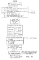
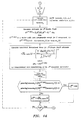
- Figure 4a illustrates the steps performed to calculate the specific model Influence Coefficients (ICs) represented by matrices H e (engine ICs) and H s (sensor ICs). These matrices consist of partial derivatives which relate percent of point changes in the performance fault parameters to percent of point changes in the measured (observed) parameters and are commonly used for this type of performance diagnostic modeling.
- the matrix P 0 represents the so-called state covariance matrix which is a common design parameter for the Kalman Filter.
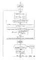
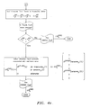
- Figure 4b illustrates the process steps by which there is calculated an associated normalized error for each single fault estimate and there is generated polarized error terms.
- Figure 4c illustrates the process steps by which the polarized error terms are processed to select the fault estimate with the minimum computed error. In addition, a determination is made whether or not to test for a double fault condition. In the event that double fault detection is warranted, Figure 4d illustrates the process steps whereby normalized and polarized error terms for each possible double fault is calculated. Lastly, in the event that double fault detection was warranted, Fig. 4e illustrates the process steps whereby it is determined whether to conclude the occurrence of a single or a double fault condition.
- the S vector of measurement non-repeatabilities contains as its components the 1-standard deviation precision error expected from the associated sensor.
- the last 3 components are the 1-standard deviation precision errors in the engine inlet pressure and temperature (P 2 and T 2 respectively) and the target power setting parameter (which varies with the engine model).
- the polarity vector is an n ⁇ 1 vector whose components have values -1, 0, or +1 with the following interpretation:
- Measurement Configuration vector M C
- Single Fault Configuration vector SF C SF
Landscapes
- Physics & Mathematics (AREA)
- General Physics & Mathematics (AREA)
- Engineering & Computer Science (AREA)
- Automation & Control Theory (AREA)
- Testing And Monitoring For Control Systems (AREA)
- Testing Of Devices, Machine Parts, Or Other Structures Thereof (AREA)
- Combined Controls Of Internal Combustion Engines (AREA)
- Testing Of Engines (AREA)
Abstract
Description
Zk = vector of Measurement Δ s at time k
Ak = vector of Measurement Δ Averages at time k


Claims (16)
- A method of fault event identification, comprising the steps of:receiving a plurality of parameter measurements;performing single fault isolation to establish one of said plurality of parameter measurements as an event start (21), one of said plurality of parameter measurements as an event detect (23), and one of said parameter measurements as an event end (25) wherein a latency period (27) extends from said event start to said event detect and a blackout period (29) extends from said event start to said event end;performing multiple fault isolation to establish a first trend line for said plurality of parameter measurements prior to said blackout period and after said blackout period;reprocessing said parameter measurements in said latency period;processing said parameter measurements in said blackout period;calculating a model IC from aero-thermal model simulation of the engine;calculating a plurality of single fault vectors;calculating an estimate for each of said single fault vectors;calculating a normalized error for each of said plurality of single fault vectors;calculating a polarized error term for each of said plurality of single fault vectors;selecting said single fault vector with smallest of said calculated normalized errors; andutilising said selected single fault vector to direct maintenance decisions.
- The method of claim 1 wherein each of said plurality of parameter measurements comprises a differential of a current measurement and an immediately preceding measurement.
- The method of claim 2 wherein each of said plurality of parameter measurement is a percentage differential.
- The method of claim 1 wherein said performing single fault isolation comprises performing a statistical analysis.
- The method of claim 1, wherein said performing single fault isolation comprises applying Kalman Filter parameter estimation.
- The method of claim 1, wherein said plurality of parameter measurements are derived from an engine.
- The method of claim 1, wherein said reprocessing said parameter measurements comprises the steps of:computing a linear regression line from said plurality of parameter measurements comprising said latency period (27); andrecomputing each of said plurality of measurements comprising said latency period as a difference between said linear regression line and an average level prior to said event start (21).
- A method of fault event identification, comprising the steps of:receiving a plurality of parameter measurements;performing single fault isolation to establish one of said plurality of parameter measurements as an event start, one of said plurality of parameter measurements as an event detect, and one of said parameter measurements as an event end wherein a latency period (27) extends from said event start (21) to said event detect (23) and a blackout period (29) extends from said event start (21) to said event end (25);performing multiple fault isolation to establish a first trend line for said plurality of parameter measurements prior to said blackout period and after said blackout period;reprocessing said parameter measurements in said latency period;processing said parameter measurements in said blackout period;calculating a model IC from said reprocessed parameter measurements;calculating a plurality of single fault vectors;calculating an estimate for each of said single fault vectors;calculating a normalized error for each of said plurality of single fault vectors;calculating a polarized error term for each of said plurality of single fault vectors; anddetermining if double fault calculation is required;calculating a plurality of double fault vectors;calculating an estimate for each of said plurality of double fault vectors;calculating a normalized error for each of said plurality of double fault vectors;calculating a polarized error term for each of said plurality of double fault vectors;selecting a fault vector comprising a smallest normalized error for each of said plurality of single fault vectors and a smallest normalized error for each of said plurality of double fault vectors; andutilising said selected single fault vector and double fault vectors to direct maintenance decisions.
- The method of claim 8 comprising the additional steps of:selecting the smaller of said smallest normalized error for each of said plurality of single fault vectors and said smallest normalized error for each of said plurality of double fault vectors.
- The method of claim 8 wherein each of said plurality of parameter measurements comprises a differential of a current measurement and an immediately preceding measurement.
- The method of claim 10 wherein each of said plurality of parameter measurement is a percentage differential.
- The method of claim 8 wherein said performing single fault isolation comprises performing a statistical analysis.
- The method of claim 8, wherein said performing single fault isolation comprises applying Kalman Filter parameter estimation.
- The method of claim 8, wherein said plurality of parameter measurements are derived from an engine.
- The method of claim 8, wherein said reprocessing said parameter measurements comprises the steps of:computing a linear regression line from said plurality of parameter measurements comprising said latency period; andrecomputing each of said plurality of measurements comprising said latency period (27) as a difference between said linear regression line and an average level prior to said event start (21).
- A method of maintaining an engine comprising analysing a plurality of parameter measurements derived from the engine to identify a fault event by the method of any preceding claim, and carrying out maintenance on the engine if a fault event is identified.
Applications Claiming Priority (2)
| Application Number | Priority Date | Filing Date | Title |
|---|---|---|---|
| US286504 | 2002-10-31 | ||
| US10/286,504 US7233884B2 (en) | 2002-10-31 | 2002-10-31 | Methodology for temporal fault event isolation and identification |
Publications (2)
| Publication Number | Publication Date |
|---|---|
| EP1416348A1 true EP1416348A1 (en) | 2004-05-06 |
| EP1416348B1 EP1416348B1 (en) | 2006-05-31 |
Family
ID=32093588
Family Applications (1)
| Application Number | Title | Priority Date | Filing Date |
|---|---|---|---|
| EP03256921A Expired - Lifetime EP1416348B1 (en) | 2002-10-31 | 2003-10-31 | Methodology for temporal fault event isolation and identification |
Country Status (4)
| Country | Link |
|---|---|
| US (1) | US7233884B2 (en) |
| EP (1) | EP1416348B1 (en) |
| JP (1) | JP2004150439A (en) |
| DE (1) | DE60305601T2 (en) |
Cited By (2)
| Publication number | Priority date | Publication date | Assignee | Title |
|---|---|---|---|---|
| EP1950634A3 (en) * | 2007-01-24 | 2008-12-17 | United Technologies Corporation | Process for adapting measurement suite configuration for gas turbine performance diagnostics |
| EP3035142A1 (en) * | 2014-12-16 | 2016-06-22 | University of Southern California | Gas turbine engine anomaly detections and fault identifications |
Families Citing this family (35)
| Publication number | Priority date | Publication date | Assignee | Title |
|---|---|---|---|---|
| US7415328B2 (en) * | 2004-10-04 | 2008-08-19 | United Technologies Corporation | Hybrid model based fault detection and isolation system |
| US20080010531A1 (en) * | 2006-06-12 | 2008-01-10 | Mks Instruments, Inc. | Classifying faults associated with a manufacturing process |
| US7472100B2 (en) * | 2006-09-29 | 2008-12-30 | United Technologies Corporation | Empirical tuning of an on board real-time gas turbine engine model |
| US20080188972A1 (en) * | 2006-10-11 | 2008-08-07 | Fisher-Rosemount Systems, Inc. | Method and System for Detecting Faults in a Process Plant |
| US8010320B2 (en) * | 2006-11-17 | 2011-08-30 | United Technologies Corporation | Reducing gas turbine performance tracking estimation non-repeatability |
| US7788014B2 (en) * | 2007-03-05 | 2010-08-31 | United Technologies Corporation | Process and methodology for root cause identification in gas turbine engine performance tracking |
| US8271103B2 (en) | 2007-05-02 | 2012-09-18 | Mks Instruments, Inc. | Automated model building and model updating |
| US7853441B2 (en) * | 2007-08-22 | 2010-12-14 | United Technologies Corp. | Systems and methods involving engine models |
| US20090112519A1 (en) * | 2007-10-31 | 2009-04-30 | United Technologies Corporation | Foreign object/domestic object damage assessment |
| US8271233B2 (en) * | 2008-04-01 | 2012-09-18 | United Technologies Corporation | Method of multi-level fault isolation design |
| US8417432B2 (en) * | 2008-04-30 | 2013-04-09 | United Technologies Corporation | Method for calculating confidence on prediction in fault diagnosis systems |
| US7788209B2 (en) * | 2008-05-05 | 2010-08-31 | United Technologies Corporation | Hybrid fault reasoning and guided troubleshooting system that uses case-based reasoning and model-based reasoning |
| JP5354174B2 (en) * | 2008-06-12 | 2013-11-27 | Jfeスチール株式会社 | Abnormality diagnosis system for machinery |
| US20100017092A1 (en) * | 2008-07-16 | 2010-01-21 | Steven Wayne Butler | Hybrid fault isolation system utilizing both model-based and empirical components |
| US8494798B2 (en) * | 2008-09-02 | 2013-07-23 | Mks Instruments, Inc. | Automated model building and batch model building for a manufacturing process, process monitoring, and fault detection |
| JP4572251B2 (en) * | 2008-09-29 | 2010-11-04 | 株式会社日立製作所 | Computer system, computer system failure sign detection method and program |
| US20100106462A1 (en) * | 2008-10-28 | 2010-04-29 | United Technologies Corp. | Systems and Methods for Diagnosing Gas Turbine Engine Faults |
| US9069345B2 (en) * | 2009-01-23 | 2015-06-30 | Mks Instruments, Inc. | Controlling a manufacturing process with a multivariate model |
| US7881880B2 (en) * | 2009-04-01 | 2011-02-01 | United Technologies Corporation | Actuator performance monitoring system |
| US8386121B1 (en) * | 2009-09-30 | 2013-02-26 | The United States Of America As Represented By The Administrator Of National Aeronautics And Space Administration | Optimized tuner selection for engine performance estimation |
| JP5359776B2 (en) * | 2009-10-23 | 2013-12-04 | セイコーエプソン株式会社 | Multi-sensor control method and multi-sensor device |
| US8306791B2 (en) * | 2009-12-21 | 2012-11-06 | United Technologies Corporation | Method and system for modeling the performance of a gas turbine engine |
| US8862433B2 (en) | 2010-05-18 | 2014-10-14 | United Technologies Corporation | Partitioning of turbomachine faults |
| WO2011162119A1 (en) * | 2010-06-24 | 2011-12-29 | 日本電気株式会社 | Degree of attention estimation device, degree of attention estimation method, and computer readable recording medium |
| US8855804B2 (en) | 2010-11-16 | 2014-10-07 | Mks Instruments, Inc. | Controlling a discrete-type manufacturing process with a multivariate model |
| US9429939B2 (en) | 2012-04-06 | 2016-08-30 | Mks Instruments, Inc. | Multivariate monitoring of a batch manufacturing process |
| US9541471B2 (en) | 2012-04-06 | 2017-01-10 | Mks Instruments, Inc. | Multivariate prediction of a batch manufacturing process |
| US20140088766A1 (en) * | 2012-09-21 | 2014-03-27 | United Technologies Corporation | Health management having system level diagnostic feedback and information fusion |
| US9043647B2 (en) * | 2013-01-02 | 2015-05-26 | Tata Consultancy Services Limited | Fault detection and localization in data centers |
| EP3239684A1 (en) * | 2016-04-29 | 2017-11-01 | Siemens Aktiengesellschaft | Fault diagnosis during testing of turbine unit |
| US10496086B2 (en) * | 2016-12-12 | 2019-12-03 | General Electric Company | Gas turbine engine fleet performance deterioration |
| US10247032B2 (en) * | 2017-03-28 | 2019-04-02 | Honeywell International Inc. | Gas turbine engine and test cell real-time diagnostic fault detection and corrective action system and method |
| CN109376445B (en) * | 2018-11-07 | 2022-10-14 | 北京动力机械研究所 | Gas turbine engine start modeling method |
| CN113793077B (en) * | 2021-11-17 | 2022-03-15 | 广东电网有限责任公司佛山供电局 | Method and system for analyzing power failure influence of power distribution network user fault |
| US20240229724A1 (en) * | 2023-01-09 | 2024-07-11 | Raytheon Technologies Corporation | Enhanced engine model for control and health monitoring |
Citations (4)
| Publication number | Priority date | Publication date | Assignee | Title |
|---|---|---|---|---|
| US5566092A (en) * | 1993-12-30 | 1996-10-15 | Caterpillar Inc. | Machine fault diagnostics system and method |
| WO1997041494A1 (en) * | 1996-04-29 | 1997-11-06 | Pulp And Paper Research Institute Of Canada | Automatic control loop monitoring and diagnostics |
| US6181975B1 (en) * | 1996-06-19 | 2001-01-30 | Arch Development Corporation | Industrial process surveillance system |
| EP1114991A2 (en) * | 1999-12-18 | 2001-07-11 | General Electric Company | Methods and systems for estimating engine faults |
Family Cites Families (3)
| Publication number | Priority date | Publication date | Assignee | Title |
|---|---|---|---|---|
| US4698780A (en) * | 1985-10-08 | 1987-10-06 | Westinghouse Electric Corp. | Method of monitoring an elevator system |
| US4911006A (en) * | 1986-10-03 | 1990-03-27 | Micro Motion Incorporated | Custody transfer meter |
| US5594180A (en) * | 1994-08-12 | 1997-01-14 | Micro Motion, Inc. | Method and apparatus for fault detection and correction in Coriolis effect mass flowmeters |
-
2002
- 2002-10-31 US US10/286,504 patent/US7233884B2/en not_active Expired - Lifetime
-
2003
- 2003-10-31 EP EP03256921A patent/EP1416348B1/en not_active Expired - Lifetime
- 2003-10-31 DE DE60305601T patent/DE60305601T2/en not_active Expired - Lifetime
- 2003-10-31 JP JP2003373180A patent/JP2004150439A/en not_active Abandoned
Patent Citations (4)
| Publication number | Priority date | Publication date | Assignee | Title |
|---|---|---|---|---|
| US5566092A (en) * | 1993-12-30 | 1996-10-15 | Caterpillar Inc. | Machine fault diagnostics system and method |
| WO1997041494A1 (en) * | 1996-04-29 | 1997-11-06 | Pulp And Paper Research Institute Of Canada | Automatic control loop monitoring and diagnostics |
| US6181975B1 (en) * | 1996-06-19 | 2001-01-30 | Arch Development Corporation | Industrial process surveillance system |
| EP1114991A2 (en) * | 1999-12-18 | 2001-07-11 | General Electric Company | Methods and systems for estimating engine faults |
Non-Patent Citations (1)
| Title |
|---|
| GRUNBERG D B ET AL: "GENERATION OF OPTIMAL AND SUBOPTIMAL STRATEGIES FOR MULTIPLE-FAULT ISOLATION", BRIDGING STANDARDS TO ADVANCING TECHNOLOGY. SAN FRANCISCO, NOV. 3 - 5, 1987, PROCEEDINGS OF THE INTERNATIONAL AUTOMATIC TESTING CONFERENCE. (AUTOTESTCON). FROM 1990: SYSTEMS READINESS TECHNOLOGY CONFERENCE, NEW YORK, IEEE, US, vol. CONF. 23, 3 November 1987 (1987-11-03), pages 125 - 131, XP000747575 * |
Cited By (3)
| Publication number | Priority date | Publication date | Assignee | Title |
|---|---|---|---|---|
| EP1950634A3 (en) * | 2007-01-24 | 2008-12-17 | United Technologies Corporation | Process for adapting measurement suite configuration for gas turbine performance diagnostics |
| EP3035142A1 (en) * | 2014-12-16 | 2016-06-22 | University of Southern California | Gas turbine engine anomaly detections and fault identifications |
| US9818242B2 (en) | 2014-12-16 | 2017-11-14 | University Of Southern California | Gas turbine engine anomaly detections and fault identifications |
Also Published As
| Publication number | Publication date |
|---|---|
| EP1416348B1 (en) | 2006-05-31 |
| JP2004150439A (en) | 2004-05-27 |
| DE60305601T2 (en) | 2007-05-03 |
| US7233884B2 (en) | 2007-06-19 |
| US20040153815A1 (en) | 2004-08-05 |
| DE60305601D1 (en) | 2006-07-06 |
Similar Documents
| Publication | Publication Date | Title |
|---|---|---|
| US7233884B2 (en) | Methodology for temporal fault event isolation and identification | |
| US7415328B2 (en) | Hybrid model based fault detection and isolation system | |
| EP1418481B1 (en) | Method for performing gas turbine performance diagnostics | |
| CA2617481C (en) | Process for adapting measurement suite configuration for gas turbine performance diagnostics | |
| EP0906593B1 (en) | Industrial process surveillance system | |
| EP1926001B1 (en) | Reducing gas turbine performance tracking estimation non-repeatability | |
| US6804600B1 (en) | Sensor error detection and compensation system and method | |
| US8671315B2 (en) | Prognostic analysis system and methods of operation | |
| US7571057B2 (en) | System and method for monitoring degradation | |
| US20140365179A1 (en) | Method and Apparatus for Detecting and Identifying Faults in a Process | |
| EP1936461A1 (en) | Gas turbine engine performance data validation | |
| WO2005073820A1 (en) | Trending system and method using window filtering | |
| US7949497B2 (en) | Machine condition monitoring using discontinuity detection | |
| CN111046331A (en) | Health monitoring method based on signal abnormity | |
| EP1927915B1 (en) | State initialization for gas turbine engine performance diagnogtics | |
| CN112231849B (en) | Axle temperature fault detection method based on NEST and SPRT fusion algorithm | |
| JP7437163B2 (en) | Diagnostic equipment, diagnostic methods and programs | |
| CN114026513B (en) | Fault prediction diagnosis device and method | |
| CN119163805B (en) | Pressure scanning valve state monitoring method, device and equipment | |
| Cangussu et al. | Automatic identification of change points for the system testing process | |
| CN121026558A (en) | PDS Ball Valve Condition Monitoring Method and System Based on Multi-Sensor Fusion | |
| Bronson et al. | Data Normalization for Engine Health Monitoring |
Legal Events
| Date | Code | Title | Description |
|---|---|---|---|
| PUAI | Public reference made under article 153(3) epc to a published international application that has entered the european phase |
Free format text: ORIGINAL CODE: 0009012 |
|
| AK | Designated contracting states |
Kind code of ref document: A1 Designated state(s): AT BE BG CH CY CZ DE DK EE ES FI FR GB GR HU IE IT LI LU MC NL PT RO SE SI SK TR |
|
| AX | Request for extension of the european patent |
Extension state: AL LT LV MK |
|
| 17P | Request for examination filed |
Effective date: 20040917 |
|
| AKX | Designation fees paid |
Designated state(s): DE FR GB |
|
| 17Q | First examination report despatched |
Effective date: 20050221 |
|
| GRAP | Despatch of communication of intention to grant a patent |
Free format text: ORIGINAL CODE: EPIDOSNIGR1 |
|
| GRAC | Information related to communication of intention to grant a patent modified |
Free format text: ORIGINAL CODE: EPIDOSCIGR1 |
|
| GRAS | Grant fee paid |
Free format text: ORIGINAL CODE: EPIDOSNIGR3 |
|
| GRAA | (expected) grant |
Free format text: ORIGINAL CODE: 0009210 |
|
| AK | Designated contracting states |
Kind code of ref document: B1 Designated state(s): DE FR GB |
|
| REG | Reference to a national code |
Ref country code: GB Ref legal event code: FG4D |
|
| REF | Corresponds to: |
Ref document number: 60305601 Country of ref document: DE Date of ref document: 20060706 Kind code of ref document: P |
|
| ET | Fr: translation filed | ||
| PLBE | No opposition filed within time limit |
Free format text: ORIGINAL CODE: 0009261 |
|
| STAA | Information on the status of an ep patent application or granted ep patent |
Free format text: STATUS: NO OPPOSITION FILED WITHIN TIME LIMIT |
|
| 26N | No opposition filed |
Effective date: 20070301 |
|
| PGFP | Annual fee paid to national office [announced via postgrant information from national office to epo] |
Ref country code: FR Payment date: 20081006 Year of fee payment: 6 |
|
| PGFP | Annual fee paid to national office [announced via postgrant information from national office to epo] |
Ref country code: GB Payment date: 20090914 Year of fee payment: 7 |
|
| REG | Reference to a national code |
Ref country code: FR Ref legal event code: ST Effective date: 20100630 |
|
| PG25 | Lapsed in a contracting state [announced via postgrant information from national office to epo] |
Ref country code: FR Free format text: LAPSE BECAUSE OF NON-PAYMENT OF DUE FEES Effective date: 20091102 |
|
| GBPC | Gb: european patent ceased through non-payment of renewal fee |
Effective date: 20101031 |
|
| PG25 | Lapsed in a contracting state [announced via postgrant information from national office to epo] |
Ref country code: GB Free format text: LAPSE BECAUSE OF NON-PAYMENT OF DUE FEES Effective date: 20101031 |
|
| REG | Reference to a national code |
Ref country code: DE Ref legal event code: R082 Ref document number: 60305601 Country of ref document: DE Representative=s name: SCHMITT-NILSON SCHRAUD WAIBEL WOHLFROM PATENTA, DE |
|
| REG | Reference to a national code |
Ref country code: DE Ref legal event code: R082 Ref document number: 60305601 Country of ref document: DE Representative=s name: SCHMITT-NILSON SCHRAUD WAIBEL WOHLFROM PATENTA, DE Ref country code: DE Ref legal event code: R081 Ref document number: 60305601 Country of ref document: DE Owner name: UNITED TECHNOLOGIES CORP. (N.D.GES.D. STAATES , US Free format text: FORMER OWNER: UNITED TECHNOLOGIES CORPORATION, HARTFORD, CONN., US |
|
| PGFP | Annual fee paid to national office [announced via postgrant information from national office to epo] |
Ref country code: DE Payment date: 20190918 Year of fee payment: 17 |
|
| REG | Reference to a national code |
Ref country code: DE Ref legal event code: R119 Ref document number: 60305601 Country of ref document: DE |
|
| PG25 | Lapsed in a contracting state [announced via postgrant information from national office to epo] |
Ref country code: DE Free format text: LAPSE BECAUSE OF NON-PAYMENT OF DUE FEES Effective date: 20210501 |