EP1416270A1 - Systems and methods for spraying and optimization of solid oxide fuel cell materials - Google Patents
Systems and methods for spraying and optimization of solid oxide fuel cell materials Download PDFInfo
- Publication number
- EP1416270A1 EP1416270A1 EP03256866A EP03256866A EP1416270A1 EP 1416270 A1 EP1416270 A1 EP 1416270A1 EP 03256866 A EP03256866 A EP 03256866A EP 03256866 A EP03256866 A EP 03256866A EP 1416270 A1 EP1416270 A1 EP 1416270A1
- Authority
- EP
- European Patent Office
- Prior art keywords
- substrate
- mixture
- operable
- gradient
- compositional
- Prior art date
- Legal status (The legal status is an assumption and is not a legal conclusion. Google has not performed a legal analysis and makes no representation as to the accuracy of the status listed.)
- Withdrawn
Links
- 238000000034 method Methods 0.000 title claims abstract description 63
- 239000000446 fuel Substances 0.000 title claims abstract description 49
- 239000007787 solid Substances 0.000 title claims abstract description 35
- 238000005507 spraying Methods 0.000 title claims abstract description 17
- 239000000463 material Substances 0.000 title claims description 67
- 238000005457 optimization Methods 0.000 title description 3
- 239000000203 mixture Substances 0.000 claims abstract description 116
- 239000000758 substrate Substances 0.000 claims abstract description 100
- 210000004027 cell Anatomy 0.000 claims abstract description 33
- 239000002001 electrolyte material Substances 0.000 claims abstract description 30
- 239000007772 electrode material Substances 0.000 claims abstract description 29
- 230000033001 locomotion Effects 0.000 claims abstract description 28
- 238000004811 liquid chromatography Methods 0.000 claims abstract description 27
- 238000011156 evaluation Methods 0.000 claims abstract description 26
- 238000004519 manufacturing process Methods 0.000 claims abstract description 19
- 210000003850 cellular structure Anatomy 0.000 claims abstract description 14
- 238000011068 loading method Methods 0.000 claims abstract description 4
- 229910052751 metal Inorganic materials 0.000 claims description 29
- 239000002184 metal Substances 0.000 claims description 29
- 239000006199 nebulizer Substances 0.000 claims description 17
- 238000002347 injection Methods 0.000 claims description 16
- 239000007924 injection Substances 0.000 claims description 16
- 239000000243 solution Substances 0.000 claims description 11
- 239000011230 binding agent Substances 0.000 claims description 10
- 229920000642 polymer Polymers 0.000 claims description 10
- 150000003839 salts Chemical class 0.000 claims description 9
- 150000002739 metals Chemical class 0.000 claims description 8
- 229910052755 nonmetal Inorganic materials 0.000 claims description 8
- 150000002843 nonmetals Chemical class 0.000 claims description 7
- 230000008021 deposition Effects 0.000 claims description 5
- 239000000523 sample Substances 0.000 description 28
- 239000003792 electrolyte Substances 0.000 description 21
- 239000000126 substance Substances 0.000 description 11
- 238000012545 processing Methods 0.000 description 9
- 239000011248 coating agent Substances 0.000 description 8
- 238000000576 coating method Methods 0.000 description 8
- 239000000919 ceramic Substances 0.000 description 7
- 238000010438 heat treatment Methods 0.000 description 7
- 238000005245 sintering Methods 0.000 description 7
- 239000010406 cathode material Substances 0.000 description 6
- 238000000151 deposition Methods 0.000 description 6
- 238000002156 mixing Methods 0.000 description 6
- 238000013459 approach Methods 0.000 description 5
- 238000003491 array Methods 0.000 description 5
- 238000006243 chemical reaction Methods 0.000 description 5
- 238000005259 measurement Methods 0.000 description 5
- 239000000843 powder Substances 0.000 description 5
- 238000012360 testing method Methods 0.000 description 5
- 230000015572 biosynthetic process Effects 0.000 description 4
- 239000007788 liquid Substances 0.000 description 4
- 230000010287 polarization Effects 0.000 description 4
- 238000005070 sampling Methods 0.000 description 4
- UFHFLCQGNIYNRP-UHFFFAOYSA-N Hydrogen Chemical compound [H][H] UFHFLCQGNIYNRP-UHFFFAOYSA-N 0.000 description 3
- QCWXUUIWCKQGHC-UHFFFAOYSA-N Zirconium Chemical compound [Zr] QCWXUUIWCKQGHC-UHFFFAOYSA-N 0.000 description 3
- 239000007789 gas Substances 0.000 description 3
- 229910052739 hydrogen Inorganic materials 0.000 description 3
- 239000001257 hydrogen Substances 0.000 description 3
- 238000011835 investigation Methods 0.000 description 3
- 239000010410 layer Substances 0.000 description 3
- 238000002663 nebulization Methods 0.000 description 3
- BASFCYQUMIYNBI-UHFFFAOYSA-N platinum Chemical compound [Pt] BASFCYQUMIYNBI-UHFFFAOYSA-N 0.000 description 3
- 238000002360 preparation method Methods 0.000 description 3
- 230000010076 replication Effects 0.000 description 3
- 238000003786 synthesis reaction Methods 0.000 description 3
- 230000002194 synthesizing effect Effects 0.000 description 3
- 229910052726 zirconium Inorganic materials 0.000 description 3
- 229910017060 Fe Cr Inorganic materials 0.000 description 2
- 229910002544 Fe-Cr Inorganic materials 0.000 description 2
- 229910002262 LaCrO3 Inorganic materials 0.000 description 2
- PXHVJJICTQNCMI-UHFFFAOYSA-N Nickel Chemical compound [Ni] PXHVJJICTQNCMI-UHFFFAOYSA-N 0.000 description 2
- 229910045601 alloy Inorganic materials 0.000 description 2
- 239000000956 alloy Substances 0.000 description 2
- 230000004888 barrier function Effects 0.000 description 2
- 239000012876 carrier material Substances 0.000 description 2
- 150000001768 cations Chemical class 0.000 description 2
- 230000008859 change Effects 0.000 description 2
- UPHIPHFJVNKLMR-UHFFFAOYSA-N chromium iron Chemical compound [Cr].[Fe] UPHIPHFJVNKLMR-UHFFFAOYSA-N 0.000 description 2
- 238000013461 design Methods 0.000 description 2
- 230000000694 effects Effects 0.000 description 2
- 229910010272 inorganic material Inorganic materials 0.000 description 2
- 239000011147 inorganic material Substances 0.000 description 2
- 230000000873 masking effect Effects 0.000 description 2
- 230000007246 mechanism Effects 0.000 description 2
- 229910021645 metal ion Inorganic materials 0.000 description 2
- 239000011148 porous material Substances 0.000 description 2
- 230000008569 process Effects 0.000 description 2
- 230000009467 reduction Effects 0.000 description 2
- 239000011833 salt mixture Substances 0.000 description 2
- 238000004544 sputter deposition Methods 0.000 description 2
- 230000004913 activation Effects 0.000 description 1
- 238000004458 analytical method Methods 0.000 description 1
- 239000010405 anode material Substances 0.000 description 1
- QVGXLLKOCUKJST-UHFFFAOYSA-N atomic oxygen Chemical compound [O] QVGXLLKOCUKJST-UHFFFAOYSA-N 0.000 description 1
- 238000001354 calcination Methods 0.000 description 1
- 150000004649 carbonic acid derivatives Chemical class 0.000 description 1
- 230000003197 catalytic effect Effects 0.000 description 1
- 238000004814 ceramic processing Methods 0.000 description 1
- CETPSERCERDGAM-UHFFFAOYSA-N ceric oxide Chemical compound O=[Ce]=O CETPSERCERDGAM-UHFFFAOYSA-N 0.000 description 1
- 229910000422 cerium(IV) oxide Inorganic materials 0.000 description 1
- 239000013043 chemical agent Substances 0.000 description 1
- 239000003795 chemical substances by application Substances 0.000 description 1
- 238000004587 chromatography analysis Methods 0.000 description 1
- 238000002485 combustion reaction Methods 0.000 description 1
- 238000007796 conventional method Methods 0.000 description 1
- 238000001816 cooling Methods 0.000 description 1
- 238000011161 development Methods 0.000 description 1
- 238000010586 diagram Methods 0.000 description 1
- 238000003618 dip coating Methods 0.000 description 1
- 238000009826 distribution Methods 0.000 description 1
- 239000002019 doping agent Substances 0.000 description 1
- 230000005611 electricity Effects 0.000 description 1
- 239000011263 electroactive material Substances 0.000 description 1
- 238000002848 electrochemical method Methods 0.000 description 1
- 238000000157 electrochemical-induced impedance spectroscopy Methods 0.000 description 1
- 239000011532 electronic conductor Substances 0.000 description 1
- 238000005516 engineering process Methods 0.000 description 1
- 230000007613 environmental effect Effects 0.000 description 1
- 238000001914 filtration Methods 0.000 description 1
- 238000013537 high throughput screening Methods 0.000 description 1
- 238000011065 in-situ storage Methods 0.000 description 1
- 230000008595 infiltration Effects 0.000 description 1
- 238000001764 infiltration Methods 0.000 description 1
- 239000012212 insulator Substances 0.000 description 1
- 150000002500 ions Chemical class 0.000 description 1
- 238000007726 management method Methods 0.000 description 1
- 239000003550 marker Substances 0.000 description 1
- 229910044991 metal oxide Inorganic materials 0.000 description 1
- 150000004706 metal oxides Chemical class 0.000 description 1
- 238000012544 monitoring process Methods 0.000 description 1
- 229910052759 nickel Inorganic materials 0.000 description 1
- 230000001590 oxidative effect Effects 0.000 description 1
- 239000011224 oxide ceramic Substances 0.000 description 1
- 229910052574 oxide ceramic Inorganic materials 0.000 description 1
- 229910052760 oxygen Inorganic materials 0.000 description 1
- 239000001301 oxygen Substances 0.000 description 1
- 238000012856 packing Methods 0.000 description 1
- 239000004033 plastic Substances 0.000 description 1
- 238000010248 power generation Methods 0.000 description 1
- 238000001556 precipitation Methods 0.000 description 1
- 239000002243 precursor Substances 0.000 description 1
- 230000005855 radiation Effects 0.000 description 1
- 239000000376 reactant Substances 0.000 description 1
- 229910052706 scandium Inorganic materials 0.000 description 1
- SIXSYDAISGFNSX-UHFFFAOYSA-N scandium atom Chemical compound [Sc] SIXSYDAISGFNSX-UHFFFAOYSA-N 0.000 description 1
- 238000000926 separation method Methods 0.000 description 1
- 239000011343 solid material Substances 0.000 description 1
- 239000002904 solvent Substances 0.000 description 1
- 238000004528 spin coating Methods 0.000 description 1
- 239000007921 spray Substances 0.000 description 1
- 239000010935 stainless steel Substances 0.000 description 1
- 229910001220 stainless steel Inorganic materials 0.000 description 1
- 230000008646 thermal stress Effects 0.000 description 1
- 229910052727 yttrium Inorganic materials 0.000 description 1
- VWQVUPCCIRVNHF-UHFFFAOYSA-N yttrium atom Chemical compound [Y] VWQVUPCCIRVNHF-UHFFFAOYSA-N 0.000 description 1
Images
Classifications
-
- H—ELECTRICITY
- H01—ELECTRIC ELEMENTS
- H01M—PROCESSES OR MEANS, e.g. BATTERIES, FOR THE DIRECT CONVERSION OF CHEMICAL ENERGY INTO ELECTRICAL ENERGY
- H01M4/00—Electrodes
- H01M4/86—Inert electrodes with catalytic activity, e.g. for fuel cells
- H01M4/88—Processes of manufacture
- H01M4/8825—Methods for deposition of the catalytic active composition
- H01M4/886—Powder spraying, e.g. wet or dry powder spraying, plasma spraying
-
- B—PERFORMING OPERATIONS; TRANSPORTING
- B01—PHYSICAL OR CHEMICAL PROCESSES OR APPARATUS IN GENERAL
- B01J—CHEMICAL OR PHYSICAL PROCESSES, e.g. CATALYSIS OR COLLOID CHEMISTRY; THEIR RELEVANT APPARATUS
- B01J19/00—Chemical, physical or physico-chemical processes in general; Their relevant apparatus
- B01J19/0046—Sequential or parallel reactions, e.g. for the synthesis of polypeptides or polynucleotides; Apparatus and devices for combinatorial chemistry or for making molecular arrays
-
- G—PHYSICS
- G01—MEASURING; TESTING
- G01N—INVESTIGATING OR ANALYSING MATERIALS BY DETERMINING THEIR CHEMICAL OR PHYSICAL PROPERTIES
- G01N30/00—Investigating or analysing materials by separation into components using adsorption, absorption or similar phenomena or using ion-exchange, e.g. chromatography or field flow fractionation
- G01N30/02—Column chromatography
- G01N30/62—Detectors specially adapted therefor
- G01N30/72—Mass spectrometers
- G01N30/7233—Mass spectrometers interfaced to liquid or supercritical fluid chromatograph
-
- H—ELECTRICITY
- H01—ELECTRIC ELEMENTS
- H01M—PROCESSES OR MEANS, e.g. BATTERIES, FOR THE DIRECT CONVERSION OF CHEMICAL ENERGY INTO ELECTRICAL ENERGY
- H01M8/00—Fuel cells; Manufacture thereof
- H01M8/10—Fuel cells with solid electrolytes
- H01M8/12—Fuel cells with solid electrolytes operating at high temperature, e.g. with stabilised ZrO2 electrolyte
-
- B—PERFORMING OPERATIONS; TRANSPORTING
- B01—PHYSICAL OR CHEMICAL PROCESSES OR APPARATUS IN GENERAL
- B01J—CHEMICAL OR PHYSICAL PROCESSES, e.g. CATALYSIS OR COLLOID CHEMISTRY; THEIR RELEVANT APPARATUS
- B01J2219/00—Chemical, physical or physico-chemical processes in general; Their relevant apparatus
- B01J2219/00274—Sequential or parallel reactions; Apparatus and devices for combinatorial chemistry or for making arrays; Chemical library technology
- B01J2219/00277—Apparatus
- B01J2219/00351—Means for dispensing and evacuation of reagents
- B01J2219/00353—Pumps
-
- B—PERFORMING OPERATIONS; TRANSPORTING
- B01—PHYSICAL OR CHEMICAL PROCESSES OR APPARATUS IN GENERAL
- B01J—CHEMICAL OR PHYSICAL PROCESSES, e.g. CATALYSIS OR COLLOID CHEMISTRY; THEIR RELEVANT APPARATUS
- B01J2219/00—Chemical, physical or physico-chemical processes in general; Their relevant apparatus
- B01J2219/00274—Sequential or parallel reactions; Apparatus and devices for combinatorial chemistry or for making arrays; Chemical library technology
- B01J2219/00277—Apparatus
- B01J2219/00351—Means for dispensing and evacuation of reagents
- B01J2219/0036—Nozzles
-
- B—PERFORMING OPERATIONS; TRANSPORTING
- B01—PHYSICAL OR CHEMICAL PROCESSES OR APPARATUS IN GENERAL
- B01J—CHEMICAL OR PHYSICAL PROCESSES, e.g. CATALYSIS OR COLLOID CHEMISTRY; THEIR RELEVANT APPARATUS
- B01J2219/00—Chemical, physical or physico-chemical processes in general; Their relevant apparatus
- B01J2219/00274—Sequential or parallel reactions; Apparatus and devices for combinatorial chemistry or for making arrays; Chemical library technology
- B01J2219/00277—Apparatus
- B01J2219/00351—Means for dispensing and evacuation of reagents
- B01J2219/00427—Means for dispensing and evacuation of reagents using masks
- B01J2219/0043—Means for dispensing and evacuation of reagents using masks for direct application of reagents, e.g. through openings in a shutter
-
- B—PERFORMING OPERATIONS; TRANSPORTING
- B01—PHYSICAL OR CHEMICAL PROCESSES OR APPARATUS IN GENERAL
- B01J—CHEMICAL OR PHYSICAL PROCESSES, e.g. CATALYSIS OR COLLOID CHEMISTRY; THEIR RELEVANT APPARATUS
- B01J2219/00—Chemical, physical or physico-chemical processes in general; Their relevant apparatus
- B01J2219/00274—Sequential or parallel reactions; Apparatus and devices for combinatorial chemistry or for making arrays; Chemical library technology
- B01J2219/00277—Apparatus
- B01J2219/00497—Features relating to the solid phase supports
- B01J2219/00527—Sheets
-
- B—PERFORMING OPERATIONS; TRANSPORTING
- B01—PHYSICAL OR CHEMICAL PROCESSES OR APPARATUS IN GENERAL
- B01J—CHEMICAL OR PHYSICAL PROCESSES, e.g. CATALYSIS OR COLLOID CHEMISTRY; THEIR RELEVANT APPARATUS
- B01J2219/00—Chemical, physical or physico-chemical processes in general; Their relevant apparatus
- B01J2219/00274—Sequential or parallel reactions; Apparatus and devices for combinatorial chemistry or for making arrays; Chemical library technology
- B01J2219/00583—Features relative to the processes being carried out
- B01J2219/00603—Making arrays on substantially continuous surfaces
- B01J2219/00659—Two-dimensional arrays
-
- B—PERFORMING OPERATIONS; TRANSPORTING
- B01—PHYSICAL OR CHEMICAL PROCESSES OR APPARATUS IN GENERAL
- B01J—CHEMICAL OR PHYSICAL PROCESSES, e.g. CATALYSIS OR COLLOID CHEMISTRY; THEIR RELEVANT APPARATUS
- B01J2219/00—Chemical, physical or physico-chemical processes in general; Their relevant apparatus
- B01J2219/00274—Sequential or parallel reactions; Apparatus and devices for combinatorial chemistry or for making arrays; Chemical library technology
- B01J2219/00718—Type of compounds synthesised
- B01J2219/00745—Inorganic compounds
-
- B—PERFORMING OPERATIONS; TRANSPORTING
- B01—PHYSICAL OR CHEMICAL PROCESSES OR APPARATUS IN GENERAL
- B01J—CHEMICAL OR PHYSICAL PROCESSES, e.g. CATALYSIS OR COLLOID CHEMISTRY; THEIR RELEVANT APPARATUS
- B01J2219/00—Chemical, physical or physico-chemical processes in general; Their relevant apparatus
- B01J2219/00274—Sequential or parallel reactions; Apparatus and devices for combinatorial chemistry or for making arrays; Chemical library technology
- B01J2219/00718—Type of compounds synthesised
- B01J2219/00745—Inorganic compounds
- B01J2219/0075—Metal based compounds
-
- C—CHEMISTRY; METALLURGY
- C40—COMBINATORIAL TECHNOLOGY
- C40B—COMBINATORIAL CHEMISTRY; LIBRARIES, e.g. CHEMICAL LIBRARIES
- C40B40/00—Libraries per se, e.g. arrays, mixtures
- C40B40/18—Libraries containing only inorganic compounds or inorganic materials
-
- C—CHEMISTRY; METALLURGY
- C40—COMBINATORIAL TECHNOLOGY
- C40B—COMBINATORIAL CHEMISTRY; LIBRARIES, e.g. CHEMICAL LIBRARIES
- C40B60/00—Apparatus specially adapted for use in combinatorial chemistry or with libraries
- C40B60/14—Apparatus specially adapted for use in combinatorial chemistry or with libraries for creating libraries
-
- H—ELECTRICITY
- H01—ELECTRIC ELEMENTS
- H01M—PROCESSES OR MEANS, e.g. BATTERIES, FOR THE DIRECT CONVERSION OF CHEMICAL ENERGY INTO ELECTRICAL ENERGY
- H01M4/00—Electrodes
- H01M4/86—Inert electrodes with catalytic activity, e.g. for fuel cells
- H01M4/8605—Porous electrodes
-
- H—ELECTRICITY
- H01—ELECTRIC ELEMENTS
- H01M—PROCESSES OR MEANS, e.g. BATTERIES, FOR THE DIRECT CONVERSION OF CHEMICAL ENERGY INTO ELECTRICAL ENERGY
- H01M4/00—Electrodes
- H01M4/86—Inert electrodes with catalytic activity, e.g. for fuel cells
- H01M4/8636—Inert electrodes with catalytic activity, e.g. for fuel cells with a gradient in another property than porosity
-
- H—ELECTRICITY
- H01—ELECTRIC ELEMENTS
- H01M—PROCESSES OR MEANS, e.g. BATTERIES, FOR THE DIRECT CONVERSION OF CHEMICAL ENERGY INTO ELECTRICAL ENERGY
- H01M8/00—Fuel cells; Manufacture thereof
- H01M8/10—Fuel cells with solid electrolytes
- H01M8/12—Fuel cells with solid electrolytes operating at high temperature, e.g. with stabilised ZrO2 electrolyte
- H01M8/1231—Fuel cells with solid electrolytes operating at high temperature, e.g. with stabilised ZrO2 electrolyte with both reactants being gaseous or vaporised
-
- H—ELECTRICITY
- H01—ELECTRIC ELEMENTS
- H01M—PROCESSES OR MEANS, e.g. BATTERIES, FOR THE DIRECT CONVERSION OF CHEMICAL ENERGY INTO ELECTRICAL ENERGY
- H01M8/00—Fuel cells; Manufacture thereof
- H01M8/10—Fuel cells with solid electrolytes
- H01M8/12—Fuel cells with solid electrolytes operating at high temperature, e.g. with stabilised ZrO2 electrolyte
- H01M8/124—Fuel cells with solid electrolytes operating at high temperature, e.g. with stabilised ZrO2 electrolyte characterised by the process of manufacturing or by the material of the electrolyte
-
- Y—GENERAL TAGGING OF NEW TECHNOLOGICAL DEVELOPMENTS; GENERAL TAGGING OF CROSS-SECTIONAL TECHNOLOGIES SPANNING OVER SEVERAL SECTIONS OF THE IPC; TECHNICAL SUBJECTS COVERED BY FORMER USPC CROSS-REFERENCE ART COLLECTIONS [XRACs] AND DIGESTS
- Y02—TECHNOLOGIES OR APPLICATIONS FOR MITIGATION OR ADAPTATION AGAINST CLIMATE CHANGE
- Y02E—REDUCTION OF GREENHOUSE GAS [GHG] EMISSIONS, RELATED TO ENERGY GENERATION, TRANSMISSION OR DISTRIBUTION
- Y02E60/00—Enabling technologies; Technologies with a potential or indirect contribution to GHG emissions mitigation
- Y02E60/30—Hydrogen technology
- Y02E60/50—Fuel cells
-
- Y—GENERAL TAGGING OF NEW TECHNOLOGICAL DEVELOPMENTS; GENERAL TAGGING OF CROSS-SECTIONAL TECHNOLOGIES SPANNING OVER SEVERAL SECTIONS OF THE IPC; TECHNICAL SUBJECTS COVERED BY FORMER USPC CROSS-REFERENCE ART COLLECTIONS [XRACs] AND DIGESTS
- Y02—TECHNOLOGIES OR APPLICATIONS FOR MITIGATION OR ADAPTATION AGAINST CLIMATE CHANGE
- Y02P—CLIMATE CHANGE MITIGATION TECHNOLOGIES IN THE PRODUCTION OR PROCESSING OF GOODS
- Y02P70/00—Climate change mitigation technologies in the production process for final industrial or consumer products
- Y02P70/50—Manufacturing or production processes characterised by the final manufactured product
Definitions
- the present invention relates generally to the field of liquid chromatography. More particularly, the present invention relates to high throughput systems and methods for the fabrication and measurement of solid oxide fuel cell components using a modified liquid chromatography instrument.
- a fuel cell is an energy conversion device capable of generating electricity and heat by electrochemically combining a gaseous fuel and an oxidizing gas via an ion-conducting electrolyte.
- the defining characteristic of a fuel cell is the ability to convert chemical energy directly into electrical energy without the need for combustion, giving much higher conversion efficiencies as compared to conventional methods.
- a fuel cell is mainly composed of an electrolyte and two electrodes, the anode and the cathode. The classification of fuel cells is generally done according to the nature of the electrolyte.
- the electrolyte is operable for preventing the two electrodes from coming into electronic contact while allowing a flow of charged ions generated at the cathode to pass through it in order to be discharged at the anode.
- the nature of the electrolyte determines the operating temperature of the fuel cell.
- the function of the electrode is to bring about a reaction between the reactant (fuel) and the electrolyte, without itself being consumed or corroded. It must also, by definition, be an electronic conductor and bring the phases into contact.
- SOFCs solid oxide fuel cells
- SOFCs are fuel cells constructed entirely from solid-state materials. SOFCs use an ion-conducting oxide ceramic as the electrolyte, and are operated in the range of about 900 °C to about 1000 °C. SOFCs provide several advantages compared to other fuel cell types, such as generating few problems with electrolyte management and having the highest efficiencies of all fuel cells (approximately 50-60%). SOFCs may be used in large-scale power generation, distributed power and vehicular applications.
- YSZ yttrium-stabilized zirconium
- electrolyte performance is relatively sensitive to the ratio of Y to Zr, and this component ratio must be carefully optimized. The same is true for other potential candidate materials for electrolytes, including Sr-doped CeO2, CGO, and the like.
- Electrode material composition is also critical to the performance of a SOFC. For example, the composition of LaxSr1-xMnO (3-d) (LSM), a common cathode material, may greatly affect its electrical conductivity and electrochemical activity.
- LSM LaxSr1-xMnO
- SOFCs are a promising technology for producing electrical energy from fuel with relatively high efficiency and low emissions
- barriers to the widespread commercial use of SOFCs include their relatively high manufacturing cost and high operating temperatures.
- the manufacturing cost is driven primarily by the need for state-of-the-art, electrolyte-supported fuel cells capable of operating at relatively high temperatures (approximately 1000 °C). Manufacturing costs may be substantially reduced if the operating temperature could be lowered to below 800 °C, allowing the use of less expensive structural components, such as stainless steel.
- a lower operating temperature would also ensure a greater overall system efficiency and a reduction in the thermal stresses in the active ceramic structures, leading to longer life expectancies.
- LSM common cathode material
- the cathodic polarization of LSM is relatively high, leading to large efficiency losses.
- new cathode compositions with lower activation polarizations are needed.
- standard ceramic processing techniques for fabricating new cathode compositions are time consuming and costly.
- new powder compositions are synthesized in a plurality of steps, including precipitation, filtration, and calcining. Because the microstructure (i.e., the porosity) of the cathode structure contributes substantially to its performance, careful processing of the powder must be performed in order to produce cathode structures with uniform microstructures. The expense associated with synthesizing such ceramic powders limits the number of cathode compositions that may be fabricated and evaluated.
- the present invention provides high-throughput systems and methods for the fabrication and evaluation of electrode and electrolyte materials for use in solid oxide fuel cells ("SOFCs").
- SOFCs solid oxide fuel cells
- the present invention comprises systems and methods for synthesizing, evaluating, and optimizing the performance of such electrodes and electrode-electrolyte combinations and uses small-scale techniques to perform such synthesis, evaluation and optimization based on variable chemical composition and processing.
- rapid device performance systems and methods coupled with structural and surface systems and methods allow for increased rates of discovery for new materials and material combinations for use in SOFCs.
- the present invention provides facile and rapid techniques for synthesizing multi-compositional inorganic materials generally. These techniques may be used to discover new inorganic materials for use in SOFCs (such as electrodes, electrolytes, interconnects, seals, and the like), phosphors, scintillators, PZT materials, and the like.
- SOFCs such as electrodes, electrolytes, interconnects, seals, and the like
- phosphors such as electrodes, electrolytes, interconnects, seals, and the like
- scintillators such as phosphors, scintillators, PZT materials, and the like.
- a method for the fabrication and evaluation of an array of electrode or electrolyte materials for use in SOFCs comprises providing a plurality of materials suitable for delivery to the surface of a substrate.
- the plurality of materials may form a gradient coating in the form of a gradient array on the surface of the substrate or, alternatively, they may infiltrate the substrate, forming an array of electrode or electrolyte materials suitable for evaluation.
- the plurality of materials may form the array of electrode or electrolyte materials by selectively altering the chemical composition and/or physical microstructure of each of a plurality of regions of the substrate.
- a plurality of components are mixed in tubes of a liquid chromatography (LC) instrument. Any number of components may be added and a gradient flow of the components may be accomplished using LC software.
- the gradient flow is formed as previously described, but after the various components are delivered to the substrate 106, a processing step is carried out which allows or causes the components to interact to form layers, blends, mixtures, and/or materials resulting from a reaction between components.
- two or more components may be delivered to predefined regions on the substrate using a parallel delivery technique, such that the components interact with each other before contacting the substrate 106. Each component may be delivered in either a uniform or gradient fashion to produce either a single stoichiometry or, alternatively, a large number of stoichiometries within a single predefined region.
- compositional libraries With the synthesis of materials for SOFCs, both chemical composition and microstructure are important variables.
- Producing a gradient flow using the methods and systems of the present invention promotes the replication of compositional libraries, thus opportunities for processing with multiple variables and microstructure control are feasible.
- Replication of the arrays allows for the investigation of multi-processing variables.
- the individual compositions in a given array may be tested for conductivity and for catalytic activity in the presence of oxygen by monitoring the overpotential at various temperatures using a multi-probe instrument. Subsequent results allow for the ranking of composition and processing based on performance measurements.
- the present invention provides a system for the fabrication and evaluation of a gradient mixture of solid oxide fuel cell components.
- the system comprises a substrate, a liquid chromatography instrument operable for simultaneously and continuously controlling 2 or more solution flow rates, an injection system operable for serially and distributively injecting samples selected from a sample library into the gradient mixture to form a multi-compositional material, and a delivery device operable for delivering the gradient mixture to the substrate.
- the system further comprises an x-y motion stage connected to the delivery device, the substrate or both, wherein motion of the x-y stage is coordinated with the delivery of the gradient mixture to the substrate, a mask operable for creating discrete or continuous gradient compositions, a shutter operable for selectively allowing/preventing the mixture from being sprayed onto the substrate by opening/closing, and a general purpose processor operable for controlling functions of at least one of the following: the liquid chromatography instrument, the injection system, the delivery device, the x-y motion stage, the mask, the shutter, and the temperature controlled heating block.
- the present invention provides a system comprising a substrate, an auto-sampler operable for simultaneously controlling the flow rates of 2 or more solid oxide fuel cell components, and wherein the auto-sampler is further operable for serially and distributively injecting samples selected from a sample library into a gradient mixture to form a multi-compositional material, a delivery apparatus operable for delivery the gradient mixture to the substrate, a mass flow controller operable for controlling the flow of the gradient mixture to the substrate, an x-y motion stage attached to either the substrate of the delivery apparatus, an a microprocessor for controlling the function of the auto-sampler, the delivery apparatus, the mass flow controller and the x-y motion stage.
- the present invention provides a method for the fabrication and evaluation of electrode and electrolyte material performance for solid oxide fuel cells.
- the method comprises providing a library of samples comprising electrode materials, electrolyte materials, metals, non-metals, soluble metal salts, organic binders, polymers, and any other components used to produce the solid oxide fuel cells, continuously and controllably supplying desired amounts of the samples to a liquid chromatography system where a multi-compositional mixture is formed, serially loading the multi-compositional mixture into a common sprayer, serially and distributively spraying the multi-compositional mixture onto a surface of a substrate using a spraying apparatus, forming a discrete or continuous gradient array of the mixture reacted on the substrate, and evaluating the performance of the mixture for use in solid oxide fuel cells.
- the systems and methods of the present invention are based on the nebulization into a hydrogen flame or the nebulization of soluble metal salt mixtures, small organic or polymer solutions to form discreet or continuous gradient arrays of materials reacted on, with or within a substrate.
- a compositional gradient is formed using a liquid chromatography instrument (LC) in which 2 or more solution flow rates may be simultaneously controlled. This provides the capability to control the amount and ratios of soluble metal salts that form the bulk of a material and allows for a wide range of compositions to be produced continuously.
- An auto-sampler of the LC instrument may be utilized to inject mixtures of other components, metal and nonmetal, into the gradient flow to form a multi-compositional material.
- Additional components may enhance a physical or chemical property, such as electrical or ionic conductivity, pore size and pore density.
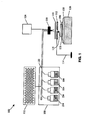
- a LC system 102 for the fabrication of a compositional gradient of electrode and electrolyte materials for use in SOFCs comprises a plurality of materials 104 (materials A, B, C and D are shown) suitable for delivery to the surface of a sample substrate 106.
- the plurality of materials 104 may form either a discrete or a continuous gradient array of materials acted on, with or within the reactive or unreactive substrate 106.
- the compositional array is formed using a LC instrument 108 in which 2 or more solution flow rates (4 are shown) are simultaneously controlled.
- the substrate 106 may be a material having a rigid or semi-rigid surface. In several embodiments, at least one surface of the substrate 106 will be substantially flat. The substrate may be reactive or unreactive, and porous or nonporous. The substrate 106 may comprise physical separations between testing regions for different SOFC materials. The substrate 106 may comprise, for example, porous or dense yttrium-stabilized zirconium ("YSZ"), a green ceramic, a plastic coated ceramic, a platinum metal, or the like.
- the surface area of the substrate is designed to meet the requirements of a particular application. Preferably, the surface area of the substrate 106 is in the range of 1 cm 2 to 50 cm 2 , more preferably, in the range of 30 cm 2 to 40 cm 2 .
- a Fe-Cr alloy or a conductive ceramic, such as LaCrO3 or platinum metal may be used for the array electrodes.
- a LaxSr1-xMnO (3-d) (“LSM”)-coated Fe-Cr alloy, platinum metal, or LaCrO3 may be used for the array electrodes.
- a predetermined region on the substrate is a localized area that is, was, or is intended to be used for the deposition of a specific solid oxide fuel cell mixture.
- the predetermined region may have any convenient shape, e.g., linear, circular, rectangular, elliptical or wedge-shaped.
- the region may be identified with a marker, such as a tag or bar code that may be used to identify which mixtures are deposited onto which predetermined region on the substrate 106.
- the surface area, number of regions and locations of the predetermined regions may depend on the particular application.
- the LC instrument 108 operable for delivering component mixtures to the surface of the substrate is positioned above or adjacent to the surface of the substrate 106.
- the liquid mixture may be aerosolized using an ultrasonic nebulizer 110 or electrostatic forces, and sprayed onto a heated substrate 106.
- a nebulizer or sprayer, plain, plasma, hydrogen flame sprayer, or any other liquid sprayer known in the art may be used.
- the sprayer may include a delivery device, such as a syringe, pipette, micro-dispenser, liquid coating device, spin coating device, dip coating device, elongate coating head, powder coating device, vapor coating device, infiltration device or any other dispensing or coating device known to those of ordinary skill in the art.
- the ultrasonic nebulizer 110 is arranged in such a way, as is illustrated in FIG. 1 for example, such that a discrete or continuous gradient array of materials is created.
- a gradient array is formed using a hydrogen flame as the deposition method.
- the ultrasonic nebulizer 110 is movable relative to the surface of the substrate 106, such that the one or more mixtures may be delivered to specific predetermined regions of the surface of the substrate 106.
- these predetermined regions may correspond to the locations of a plurality of holes or openings of a mask 112.
- the mixture of materials deposited onto the substrate 106 forms the array 102 of SOFC components.
- physical masking systems may be employed in combination with various deposition techniques in order to apply components onto the substrate 106 in a combinatorial fashion, thereby creating arrays of resulting materials at predetermined locations on the substrate 106.
- the arrays of component materials will usually differ in thickness across the substrate 106.
- the components can, for example, be dispensed to the substrate 106 in the form of a gas, a liquid or a powder. Additionally, such dispensing systems may be manual or, alternatively, may be automated using, for example, robotics techniques.
- the substrate 106 may be disposed underneath and adjacent to the mask 112.
- the mask 112 comprises a plate, sheet, film, coating or the like supported by a holder 114.
- the mask may not be a necessary component of the system if a gradient is known.
- the mask comprises one or more holes 116 disposed therethrough or openings disposed therein.
- a hole may have a diameter of about 1 mm.
- Each of the one or more holes 116 or openings may be, for example, substantially circular, oblong, square, rectangular, triangular or a more complex shape.
- the mask 112 is disposed adjacent to a surface of the substrate 106 such that material passing through each of the plurality of holes is selectively prevented or shielded from contacting predetermined regions of the surface of the substrate 106.
- a shutter 118 may be disposed between the ultrasonic nebulizer 110 and mask 112. The shutter is a mechanical device that selectively allows/prevents a mixture from being sprayed on to the substrate 106 by opening/closing.
- Predetermined combinations of materials are mixed in the LC instrument 108 prior to the actual dispensing or delivery.
- Mixing may take place within a plurality of tubes 120 of the LC instrument 108 (1 tube is illustrated in FIG. 1).
- the plurality of materials 104, or precursor components Prior to being delivered to the surface of the substrate 106, the plurality of materials 104, or precursor components, may be mixed in the plurality of tubes or mixed using a mixing device.
- the mixing device may include one or more tubes incorporating one or more baffles, a variable-speed rotary mixer, a screw mixer, a sonic mixer or the like.
- the LC system 102 of the present invention comprises a sample injection system 122, such as an auto-sampler, for serially and distributively injecting samples selected from a sample library, into the gradient flow to form a multi-compositional material.
- the auto-sampler may be used to inject mixtures of metals, non-metals, organic binders and polymers for structural variation. Pre-mixed vials may contain matters or polymers that doped in to study the effect on the gradient.
- the injection system 122 may be of various design and configuration and may comprise any number of samples.
- the injection system 122 may comprise an array of wells or sample vials. The flow rates of the samples are simultaneously controlled.
- the sample injection system 122 may comprise an injector and a multi-port switching valve.
- the injector provides a motive force for injecting a sample under pressure through the multi-port switching valve into the mixing tubes 120 and the gradient flow being supplied to the ultrasonic nebulizer 110, or other sprayer.
- the multi-port switching valve provides sequential distribution of the samples to the gradient flow.
- the injector and multi-port switching valve may be separate components or a single component.
- Sample injection into the gradient flow may be done so in any manner known in the art. Samples may also be subject to preparation steps prior to being injected. Preparation steps may include heating, cooling and mixing with other samples prior to injection. In one example, only one sample is drawn into the injector at a time. The one sample is injected into the gradient flow before drawing the next sample into the injector. In a second example, however, two or more samples may be drawn into the injector sequentially and allowed to mix, such that the two or more samples reside in the injector at the same time. The flexibility of the injection system 122 provides for any variety of sample combinations and the rapid introduction of the one or more samples into the gradient flow.
- the injection system 122 may be manually or automatically controlled.
- a metal sample may be drawn from the sample library manually with a syringe-type instrument and manually delivered to the tubes 120 containing the gradient flow.
- some function of the system is performed automatically, such as sample selection or delivery.
- Solvent concentrations may be programmed to increase, hold steady, go down or any other function.
- the samples are drawn from their respective vials and delivered in a fully automated manner, such as with an auto-sampler.
- a microprocessor of the auto-sampler may be programmed to direct the auto-sampler to withdraw a sample from a sample vial into the injector, and then direct the injector to a port for injecting the sample into the gradient flow tube 120.
- the auto-sampler may be programmed to automatically sample each vial of the library of samples in an ordered fashion.
- the microprocessor of the auto-sampler comprises a user-interface that may be programmed to allow for various sampling protocols. The auto-sampler may also be controlled manually.
- Solution flow rates of 2 or more solutions may be simultaneously controlled using a mass flow controller 124.
- the solution flow rates may be controlled using metering pumps located in the LC instrumentation. Any gas for nebulization, reaction, and flame may be controlled by the mass flow controller 124.
- the mass flow controller 124 provides the capability to control the amount and ratios of soluble metal salts that form the bulk of a material, as well as materials from the injection system 122 that make up the residual. Further, the mass flow controller 124 allows for a wide range of compositions to be produced continuously.
- the ultrasonic nebulizer 110 is movable relative to the surface of the substrate 106, either via movement of the nebulizer 110 or via movement of the substrate 106, such as through the use of a programmable x-y stage 126 or the like.
- a continuous compositional gradient may be created by applying different feed rates to 2 or more metal containing solutions and simultaneously moving the target in either the x or y direction.
- the continuous gradient can be captured spatially by using the x-y motion stage 126 and coordinating the flow with the rate of motion.
- Discrete compositions may be created by the interruption of the flow coordinated with the x-y stage 126. This may be accomplished with various masking techniques or by splitting off the flow until the desired composition is present.
- a temperature controlled heating block 128 is operable for sintering the array of electrode or electrolyte materials to remove any binders and/or carrier materials prior to SOFC assembly and evaluation. In the case of ceramics a high temperature may be desired. Disposed between the heating block 128 and the x-y stage 126, an insulator 130 protects the x-y stage 126 from heat.
- the heating block 12 includes a temperature control device. Sintering of the metal salt mixtures may take place in-situ with spraying, however, in most cases, post-spray sintering may be necessary.
- the methods and systems of the present invention are used to investigate materials for both electrode and electrolyte materials for SOFCs.
- the plurality of materials 104 forms the gradient array of electrode or electrolyte materials on the substrate 106.
- the plurality of materials 104 may form, for example, a discrete array of electrode materials separated by electrolyte material, a continuous array of electrode materials, a discrete array of electrolyte materials, a continuous array of electrolyte materials, or any combination thereof.
- Electrode and electrolyte mixtures are selected by characterizing properties of interest of the mixtures, or by characterizing a property of interest of a component, such as zirconium (Zr 4+ ), yttrium (Y 3+ ), nickel (Ni 2+ ), scandium (Sc 2+ ), etc.
- the property is detected over a period of time and as a percentage of mixture composition, such that a variation in the property is observed and detected and the rate of change of variation of the property is observed and detected.
- a property of interest is any property that affects the performance of electrode and electrode-electrolyte combinations.
- a maskless approach may be employed.
- a decomposable substrate allows for the formation of a gradient solid. Sputtering a metal on one side of the ceramic substrate creates a common electrode, sputtering an array of discrete metal contacts on the other side, using the mask 112, isolates a compositional spot between the two electrodes for electrochemical characterization.
- cathode materials a similar approach may be performed by spraying either discrete or continuous gradient mixtures on an anode-electrolyte substrate. The anode provides a general common for each cell while a metal contact may be sputtered onto the cathode materials using the mask 112. Such a design allows for the electrochemical evaluation of the materials under fuel containing conditions.
- the plurality of materials 104 comprises SOFC components, the individual substances that are deposited onto the substrate 106.
- the components may act upon one another to produce a particular material. Components may react directly with each other or with an external energy source such as thermal radiation. An additional material or a chemical substance present in the substrate 106 or added to the components may also act upon the components.
- the components form layers, blends, mixtures or combinations thereof.
- the plurality of materials 104 may comprise, for example, a plurality of materials suitable for providing predetermined metal ions, metal cations, combinations of metal ions, and/or combinations of metal cations to the surface of the substrate 106, such as metal oxides, metal carbonates, metal salts and the like.
- the plurality of materials 104 may comprise metal solutions that contain metals for bulk and dopant purposes, along with organic binders or polymers for structural variation. Other suitable materials known to those of ordinary skill in the art may also be used for both the electrodes and the electrolytes.
- the plurality of materials 104 may further include binders and/or carrier materials to enhance the coating and/or infiltrating processes.
- the components or combination of components that have been deposited on to a predefined region of the substrate 104 comprise a layer, blend or mixture of components in the form of a gradient array. Each component in the mixture may be independently varied. A mixture comprises two or more substances. The resulting materials of the gradient array are screened for specific properties or characteristics to determine their relative performance.
- an array of electro-active materials may be formed as described above.
- a chemical agent may be added to a spot of interest in an attempt to influence change in the microstructure of that spot.
- an agent may be added that, after sintering, allows for variable control of porosity or packing density. This allows for both compositional and micro-structural control on a small scale. Relationships between microstructure, composition, and material performance may thus be discovered and optimized rapidly.
- the systems and methods of the present invention describe the creation of a multi-composition cell, which allows for the rapid study of cathode and anode materials suitable for use in SOFCs.
- a multi-composition cell By spraying an anode of a uniform material with a common cathode material, different regions of the multi-composition cell may be measured and regions evaluated for performance. Performance to composition may determined rapidly using a multi-channel or multi-electrode analyzer.
- the system for the evaluation of an array of electrode or electrolyte materials for use in SOFCs also includes a testing device operably coupled to each of a plurality of regions of the substrate 106 via one or more leads, probes, sensors, or the like, referred to herein as one or more sampling mechanisms.
- the testing device gathers data from the one or more sampling mechanisms and, optionally, in combination with a computer, evaluates and compares the relative performance of each mixture of the gradient array.
- the testing device and the computer may comprise a multi-channel electrochemical workstation capable of sampling each member of the array in series or in parallel.
- electrical resistance, over-potential, polarization current or the like may be measured, evaluated and compared.
- Each of the individual materials may be screened or interrogated for the same material characteristic.
- over-potential may be measured using a constant-current approach.
- Polarization current may be measured using a constant-voltage approach.
- ionic resistance, open circuit voltage, or the like may be measured, evaluated, and compared using an alternating-current ("AC") impedance analyzer, a potentiastat or the like.
- AC alternating-current
- ionic resistance it is measured using electrochemical impedance spectroscopy at a single frequency.
- Electrodes, electrolytes, and SOFCs are known to those of ordinary skill in the art and may be implemented in conjunction with the systems and methods of the present invention. Such tools and techniques may also be implemented in conjunction with an environmental control device operable for isolating the array of electrodes, electrolytes, or SOFCs from the surrounding environment. Once screened, the individual materials may be ranked or otherwise compared relative to each other with respect to a material characteristic under investigation.
- One or more microprocessors may be employed for automating and controlling every aspect of the LC systems of the present invention, including: the LC instrument 108, mixing tube 120, injection system 122, mass flow controller 124, ultrasonic nebulizer 110, shutter 118, mask 112, x-y stage 126, temperature controlled heating block 128, testing equipment, sensors, compositional gradients, temperature gradients, sample selection, sample preparation and any other operation or system component.
Landscapes
- Chemical & Material Sciences (AREA)
- Chemical Kinetics & Catalysis (AREA)
- Engineering & Computer Science (AREA)
- Organic Chemistry (AREA)
- Life Sciences & Earth Sciences (AREA)
- General Chemical & Material Sciences (AREA)
- Electrochemistry (AREA)
- Manufacturing & Machinery (AREA)
- Analytical Chemistry (AREA)
- Pathology (AREA)
- Immunology (AREA)
- General Physics & Mathematics (AREA)
- General Health & Medical Sciences (AREA)
- Biochemistry (AREA)
- Physics & Mathematics (AREA)
- Sustainable Development (AREA)
- Sustainable Energy (AREA)
- Health & Medical Sciences (AREA)
- Fuel Cell (AREA)
Abstract
Systems and methods for high-throughput fabrication and evaluation of
electrode and electrolyte material performance for solid oxide fuel cells. A
system comprising a substrate (106), an auto-sampler operable for
simultaneously controlling the flow rates of 2 or more solid oxide fuel cell
components, a delivery apparatus, a mass flow controller (124), an x-y motion
stage (126), and a microprocessor operable for controlling the system. A
method comprising providing a library of samples, continuously and
controllable supplying desired amounts of the samples to a liquid
chromatography system (102) where a multi-compositional mixture is formed,
serially loading the multi-compositional mixture into a common sprayer,
serially and distributively spraying the multi-compositional mixture onto a
surface of a substrate (106), forming a discrete or continuous gradient array of
the mixture reacted on the substrate (106), and evaluating the performance of
the mixture for use in solid oxide fuel cells.
Description
The present invention relates generally to the field of liquid chromatography.
More particularly, the present invention relates to high throughput systems
and methods for the fabrication and measurement of solid oxide fuel cell
components using a modified liquid chromatography instrument.
A fuel cell is an energy conversion device capable of generating electricity
and heat by electrochemically combining a gaseous fuel and an oxidizing gas
via an ion-conducting electrolyte. The defining characteristic of a fuel cell is
the ability to convert chemical energy directly into electrical energy without the
need for combustion, giving much higher conversion efficiencies as compared
to conventional methods. A fuel cell is mainly composed of an electrolyte and
two electrodes, the anode and the cathode. The classification of fuel cells is
generally done according to the nature of the electrolyte.
The electrolyte is operable for preventing the two electrodes from coming into
electronic contact while allowing a flow of charged ions generated at the
cathode to pass through it in order to be discharged at the anode. The nature
of the electrolyte determines the operating temperature of the fuel cell. The
function of the electrode is to bring about a reaction between the reactant
(fuel) and the electrolyte, without itself being consumed or corroded. It must
also, by definition, be an electronic conductor and bring the phases into
contact.
There are many different types of fuel cells, and several parameters may vary
depending on what the fuel cell is used for. For example, solid oxide fuel cells
(SOFCs) are fuel cells constructed entirely from solid-state materials. SOFCs
use an ion-conducting oxide ceramic as the electrolyte, and are operated in
the range of about 900 °C to about 1000 °C. SOFCs provide several
advantages compared to other fuel cell types, such as generating few
problems with electrolyte management and having the highest efficiencies of
all fuel cells (approximately 50-60%). SOFCs may be used in large-scale
power generation, distributed power and vehicular applications.
One of the key challenges in developing a SOFC is developing high-performance
electrode and electrolyte materials that meet SOFC performance
and cost requirements. While there are lists of potential candidate materials
for both electrodes and electrolytes, significant efforts are required to optimize
material combinations, chemical compositions, processing conditions and the
like. This is especially true as the vast majority of such potential candidate
materials are either ternary or quaternary-based.
For example, yttrium-stabilized zirconium (YSZ) is commonly used as an
electrolyte material in SOFCs. However, electrolyte performance is relatively
sensitive to the ratio of Y to Zr, and this component ratio must be carefully
optimized. The same is true for other potential candidate materials for
electrolytes, including Sr-doped CeO2, CGO, and the like. Electrode material
composition is also critical to the performance of a SOFC. For example, the
composition of LaxSr1-xMnO (3-d) (LSM), a common cathode material, may
greatly affect its electrical conductivity and electrochemical activity.
Typically, various combinations of elements or components with varying
chemical compositions are individually formulated and tested in order to
achieve optimal performance for electrode and electrolyte materials, a
relatively slow, labor-intensive, and costly process. Thus, what are needed
are high-throughput systems and methods that make SOFC-related material
development more efficient. The systems and methods of the present
invention use a combinatorial or small-scale approach to achieve the high-throughput
fabrication, evaluation and optimization of electrode and
electrolyte materials for use in SOFCs.
Likewise, although SOFCs are a promising technology for producing electrical
energy from fuel with relatively high efficiency and low emissions, barriers to
the widespread commercial use of SOFCs include their relatively high
manufacturing cost and high operating temperatures. The manufacturing cost
is driven primarily by the need for state-of-the-art, electrolyte-supported fuel
cells capable of operating at relatively high temperatures (approximately 1000
°C). Manufacturing costs may be substantially reduced if the operating
temperature could be lowered to below 800 °C, allowing the use of less
expensive structural components, such as stainless steel. A lower operating
temperature would also ensure a greater overall system efficiency and a
reduction in the thermal stresses in the active ceramic structures, leading to
longer life expectancies.
One of the barriers to a reduction in the operating temperature of SOFCs is
the efficiency of the common cathode material, LSM. At intermediate
temperatures, the cathodic polarization of LSM is relatively high, leading to
large efficiency losses. Thus, new cathode compositions with lower activation
polarizations are needed. However, standard ceramic processing techniques
for fabricating new cathode compositions are time consuming and costly.
Typically, new powder compositions are synthesized in a plurality of steps,
including precipitation, filtration, and calcining. Because the microstructure
(i.e., the porosity) of the cathode structure contributes substantially to its
performance, careful processing of the powder must be performed in order to
produce cathode structures with uniform microstructures. The expense
associated with synthesizing such ceramic powders limits the number of
cathode compositions that may be fabricated and evaluated.
Thus, what is needed are high-throughput systems and methods for the
fabrication and evaluation of electrolyte and electrode material performance
for solid oxide fuel cells. Further, what is needed are systems and methods to
synthesize and optimize the performance of electrode and electrolyte
combinations. Still further, what is needed are small scale techniques to
optimize these materials based on chemical composition and variable
processing. Rapid device performance methods coupled with structural and
surface methods would allow for an increased discovery rate of new materials
for SOFCs.
In various embodiments, the present invention provides high-throughput
systems and methods for the fabrication and evaluation of electrode and
electrolyte materials for use in solid oxide fuel cells ("SOFCs"). The present
invention comprises systems and methods for synthesizing, evaluating, and
optimizing the performance of such electrodes and electrode-electrolyte
combinations and uses small-scale techniques to perform such synthesis,
evaluation and optimization based on variable chemical composition and
processing. Advantageously, rapid device performance systems and
methods coupled with structural and surface systems and methods allow for
increased rates of discovery for new materials and material combinations for
use in SOFCs.
In various embodiments, the present invention provides facile and rapid
techniques for synthesizing multi-compositional inorganic materials generally.
These techniques may be used to discover new inorganic materials for use in
SOFCs (such as electrodes, electrolytes, interconnects, seals, and the like),
phosphors, scintillators, PZT materials, and the like. The techniques allow for
the synthesis and analysis of gradient or spatially resolved compositions that
may be used to offset non-steady-state applications.
In one embodiment of the present invention, a method for the fabrication and
evaluation of an array of electrode or electrolyte materials for use in SOFCs
comprises providing a plurality of materials suitable for delivery to the surface
of a substrate. As described above, the plurality of materials may form a
gradient coating in the form of a gradient array on the surface of the substrate
or, alternatively, they may infiltrate the substrate, forming an array of electrode
or electrolyte materials suitable for evaluation. The plurality of materials may
form the array of electrode or electrolyte materials by selectively altering the
chemical composition and/or physical microstructure of each of a plurality of
regions of the substrate.
In another embodiment, for example, a plurality of components are mixed in
tubes of a liquid chromatography (LC) instrument. Any number of
components may be added and a gradient flow of the components may be
accomplished using LC software. In yet another embodiment, the gradient
flow is formed as previously described, but after the various components are
delivered to the substrate 106, a processing step is carried out which allows
or causes the components to interact to form layers, blends, mixtures, and/or
materials resulting from a reaction between components. In a further
embodiment, two or more components may be delivered to predefined
regions on the substrate using a parallel delivery technique, such that the
components interact with each other before contacting the substrate 106.
Each component may be delivered in either a uniform or gradient fashion to
produce either a single stoichiometry or, alternatively, a large number of
stoichiometries within a single predefined region.
With the synthesis of materials for SOFCs, both chemical composition and
microstructure are important variables. Producing a gradient flow using the
methods and systems of the present invention promotes the replication of
compositional libraries, thus opportunities for processing with multiple
variables and microstructure control are feasible. Replication of the arrays
allows for the investigation of multi-processing variables. The individual
compositions in a given array may be tested for conductivity and for catalytic
activity in the presence of oxygen by monitoring the overpotential at various
temperatures using a multi-probe instrument. Subsequent results allow for
the ranking of composition and processing based on performance
measurements.
In a still further embodiment, the present invention provides a system for the
fabrication and evaluation of a gradient mixture of solid oxide fuel cell
components. The system comprises a substrate, a liquid chromatography
instrument operable for simultaneously and continuously controlling 2 or more
solution flow rates, an injection system operable for serially and distributively
injecting samples selected from a sample library into the gradient mixture to
form a multi-compositional material, and a delivery device operable for
delivering the gradient mixture to the substrate.
In a still further embodiment, the system further comprises an x-y motion
stage connected to the delivery device, the substrate or both, wherein motion
of the x-y stage is coordinated with the delivery of the gradient mixture to the
substrate, a mask operable for creating discrete or continuous gradient
compositions, a shutter operable for selectively allowing/preventing the
mixture from being sprayed onto the substrate by opening/closing, and a
general purpose processor operable for controlling functions of at least one of
the following: the liquid chromatography instrument, the injection system, the
delivery device, the x-y motion stage, the mask, the shutter, and the
temperature controlled heating block.
In a still further embodiment, the present invention provides a system
comprising a substrate, an auto-sampler operable for simultaneously
controlling the flow rates of 2 or more solid oxide fuel cell components, and
wherein the auto-sampler is further operable for serially and distributively
injecting samples selected from a sample library into a gradient mixture to
form a multi-compositional material, a delivery apparatus operable for delivery
the gradient mixture to the substrate, a mass flow controller operable for
controlling the flow of the gradient mixture to the substrate, an x-y motion
stage attached to either the substrate of the delivery apparatus, an a
microprocessor for controlling the function of the auto-sampler, the delivery
apparatus, the mass flow controller and the x-y motion stage.
In a still further embodiment, the present invention provides a method for the
fabrication and evaluation of electrode and electrolyte material performance
for solid oxide fuel cells. The method comprises providing a library of
samples comprising electrode materials, electrolyte materials, metals, non-metals,
soluble metal salts, organic binders, polymers, and any other
components used to produce the solid oxide fuel cells, continuously and
controllably supplying desired amounts of the samples to a liquid
chromatography system where a multi-compositional mixture is formed,
serially loading the multi-compositional mixture into a common sprayer,
serially and distributively spraying the multi-compositional mixture onto a
surface of a substrate using a spraying apparatus, forming a discrete or
continuous gradient array of the mixture reacted on the substrate, and
evaluating the performance of the mixture for use in solid oxide fuel cells.
The invention will now be described in greater detail, by way of example, with
reference to the drawings, the single figure of which is a schematic diagram of
a liquid chromatography (LC) system for studying SOFC components in
accordance with an exemplary embodiment of the present invention.
The methods and systems described below apply to solid oxide fuel cell
materials, however, in principle also apply to any high throughput screening
technique employing liquid chromatography instrumentation or the like.
In various embodiments, the systems and methods of the present invention
are based on the nebulization into a hydrogen flame or the nebulization of
soluble metal salt mixtures, small organic or polymer solutions to form
discreet or continuous gradient arrays of materials reacted on, with or within a
substrate. A compositional gradient is formed using a liquid chromatography
instrument (LC) in which 2 or more solution flow rates may be simultaneously
controlled. This provides the capability to control the amount and ratios of
soluble metal salts that form the bulk of a material and allows for a wide range
of compositions to be produced continuously. An auto-sampler of the LC
instrument may be utilized to inject mixtures of other components, metal and
nonmetal, into the gradient flow to form a multi-compositional material.
Additional components may enhance a physical or chemical property, such as
electrical or ionic conductivity, pore size and pore density. The facile rapid
method for making SOFC materials with the methods and systems of the
present invention promote the replication of compositional libraries, thus the
opportunity for processing with multiple variables and allowing another
dimension towards microstructure control.
With reference to FIG. 1, in one embodiment of the present invention, a LC
system 102 for the fabrication of a compositional gradient of electrode and
electrolyte materials for use in SOFCs comprises a plurality of materials 104
(materials A, B, C and D are shown) suitable for delivery to the surface of a
sample substrate 106. The plurality of materials 104 may form either a
discrete or a continuous gradient array of materials acted on, with or within
the reactive or unreactive substrate 106. The compositional array is formed
using a LC instrument 108 in which 2 or more solution flow rates (4 are
shown) are simultaneously controlled.
The substrate 106 may be a material having a rigid or semi-rigid surface. In
several embodiments, at least one surface of the substrate 106 will be
substantially flat. The substrate may be reactive or unreactive, and porous or
nonporous. The substrate 106 may comprise physical separations between
testing regions for different SOFC materials. The substrate 106 may
comprise, for example, porous or dense yttrium-stabilized zirconium ("YSZ"),
a green ceramic, a plastic coated ceramic, a platinum metal, or the like. The
surface area of the substrate is designed to meet the requirements of a
particular application. Preferably, the surface area of the substrate 106 is in
the range of 1 cm2 to 50 cm2, more preferably, in the range of 30 cm2 to 40
cm2. For the evaluation of electrode materials for use in SOFCs, a Fe-Cr alloy
or a conductive ceramic, such as LaCrO3 or platinum metal, may be used for
the array electrodes. For the evaluation of electrolyte materials for use in
SOFCs, a LaxSr1-xMnO (3-d) ("LSM")-coated Fe-Cr alloy, platinum metal, or
LaCrO3 may be used for the array electrodes.
A predetermined region on the substrate is a localized area that is, was, or is
intended to be used for the deposition of a specific solid oxide fuel cell
mixture. The predetermined region may have any convenient shape, e.g.,
linear, circular, rectangular, elliptical or wedge-shaped. The region may be
identified with a marker, such as a tag or bar code that may be used to
identify which mixtures are deposited onto which predetermined region on the
substrate 106. The surface area, number of regions and locations of the
predetermined regions may depend on the particular application.
The LC instrument 108 operable for delivering component mixtures to the
surface of the substrate is positioned above or adjacent to the surface of the
substrate 106. To form the solid materials, the liquid mixture may be
aerosolized using an ultrasonic nebulizer 110 or electrostatic forces, and
sprayed onto a heated substrate 106. In various embodiments, a nebulizer or
sprayer, plain, plasma, hydrogen flame sprayer, or any other liquid sprayer
known in the art may be used. The sprayer may include a delivery device,
such as a syringe, pipette, micro-dispenser, liquid coating device, spin coating
device, dip coating device, elongate coating head, powder coating device,
vapor coating device, infiltration device or any other dispensing or coating
device known to those of ordinary skill in the art. The ultrasonic nebulizer 110
is arranged in such a way, as is illustrated in FIG. 1 for example, such that a
discrete or continuous gradient array of materials is created. In one
embodiment, a gradient array is formed using a hydrogen flame as the
deposition method. Preferably, the ultrasonic nebulizer 110 is movable
relative to the surface of the substrate 106, such that the one or more
mixtures may be delivered to specific predetermined regions of the surface of
the substrate 106. Optionally, these predetermined regions may correspond
to the locations of a plurality of holes or openings of a mask 112. The mixture
of materials deposited onto the substrate 106 forms the array 102 of SOFC
components.
Generally, physical masking systems may be employed in combination with
various deposition techniques in order to apply components onto the
substrate 106 in a combinatorial fashion, thereby creating arrays of resulting
materials at predetermined locations on the substrate 106. The arrays of
component materials will usually differ in thickness across the substrate 106.
The components can, for example, be dispensed to the substrate 106 in the
form of a gas, a liquid or a powder. Additionally, such dispensing systems
may be manual or, alternatively, may be automated using, for example,
robotics techniques. The substrate 106 may be disposed underneath and
adjacent to the mask 112. Typically, the mask 112 comprises a plate, sheet,
film, coating or the like supported by a holder 114. The mask may not be a
necessary component of the system if a gradient is known. The mask
comprises one or more holes 116 disposed therethrough or openings
disposed therein. In one example, a hole may have a diameter of about 1
mm. Each of the one or more holes 116 or openings may be, for example,
substantially circular, oblong, square, rectangular, triangular or a more
complex shape. The mask 112 is disposed adjacent to a surface of the
substrate 106 such that material passing through each of the plurality of holes
is selectively prevented or shielded from contacting predetermined regions of
the surface of the substrate 106. A shutter 118 may be disposed between the
ultrasonic nebulizer 110 and mask 112. The shutter is a mechanical device
that selectively allows/prevents a mixture from being sprayed on to the
substrate 106 by opening/closing.
Predetermined combinations of materials (e.g. A, B, C and D) are mixed in the
LC instrument 108 prior to the actual dispensing or delivery. Mixing may take
place within a plurality of tubes 120 of the LC instrument 108 (1 tube is
illustrated in FIG. 1). Prior to being delivered to the surface of the substrate
106, the plurality of materials 104, or precursor components, may be mixed in
the plurality of tubes or mixed using a mixing device. The mixing device may
include one or more tubes incorporating one or more baffles, a variable-speed
rotary mixer, a screw mixer, a sonic mixer or the like.
According to one embodiment, with reference to FIG. 1, the LC system 102 of
the present invention comprises a sample injection system 122, such as an
auto-sampler, for serially and distributively injecting samples selected from a
sample library, into the gradient flow to form a multi-compositional material.
The auto-sampler may be used to inject mixtures of metals, non-metals,
organic binders and polymers for structural variation. Pre-mixed vials may
contain matters or polymers that doped in to study the effect on the gradient.
With reference to FIG. 1, approximately 100 samples are shown, however, the
injection system 122 may be of various design and configuration and may
comprise any number of samples. The injection system 122 may comprise an
array of wells or sample vials. The flow rates of the samples are
simultaneously controlled. This provides the capability to control the amount
and ratios of bulk components as well as other components that form the
residual of the mixture. The sample injection system 122 may comprise an
injector and a multi-port switching valve. The injector provides a motive force
for injecting a sample under pressure through the multi-port switching valve
into the mixing tubes 120 and the gradient flow being supplied to the
ultrasonic nebulizer 110, or other sprayer. The multi-port switching valve
provides sequential distribution of the samples to the gradient flow. The
injector and multi-port switching valve may be separate components or a
single component.
Sample injection into the gradient flow may be done so in any manner known
in the art. Samples may also be subject to preparation steps prior to being
injected. Preparation steps may include heating, cooling and mixing with
other samples prior to injection. In one example, only one sample is drawn
into the injector at a time. The one sample is injected into the gradient flow
before drawing the next sample into the injector. In a second example,
however, two or more samples may be drawn into the injector sequentially
and allowed to mix, such that the two or more samples reside in the injector at
the same time. The flexibility of the injection system 122 provides for any
variety of sample combinations and the rapid introduction of the one or more
samples into the gradient flow.
The injection system 122 may be manually or automatically controlled. For
example, a metal sample may be drawn from the sample library manually with
a syringe-type instrument and manually delivered to the tubes 120 containing
the gradient flow. In an automatic system, some function of the system is
performed automatically, such as sample selection or delivery. Solvent
concentrations may be programmed to increase, hold steady, go down or any
other function. Preferably, in order to rapidly and accurately select samples
and proper measurements, the samples are drawn from their respective vials
and delivered in a fully automated manner, such as with an auto-sampler. A
microprocessor of the auto-sampler may be programmed to direct the auto-sampler
to withdraw a sample from a sample vial into the injector, and then
direct the injector to a port for injecting the sample into the gradient flow tube
120. In one embodiment, the auto-sampler may be programmed to
automatically sample each vial of the library of samples in an ordered fashion.
Preferably, the microprocessor of the auto-sampler comprises a user-interface
that may be programmed to allow for various sampling protocols. The auto-sampler
may also be controlled manually.
Solution flow rates of 2 or more solutions may be simultaneously controlled
using a mass flow controller 124. The solution flow rates may be controlled
using metering pumps located in the LC instrumentation. Any gas for
nebulization, reaction, and flame may be controlled by the mass flow
controller 124. The mass flow controller 124 provides the capability to control
the amount and ratios of soluble metal salts that form the bulk of a material,
as well as materials from the injection system 122 that make up the residual.
Further, the mass flow controller 124 allows for a wide range of compositions
to be produced continuously.
Preferably, the ultrasonic nebulizer 110 is movable relative to the surface of
the substrate 106, either via movement of the nebulizer 110 or via movement
of the substrate 106, such as through the use of a programmable x-y stage
126 or the like. A continuous compositional gradient may be created by
applying different feed rates to 2 or more metal containing solutions and
simultaneously moving the target in either the x or y direction. The continuous
gradient can be captured spatially by using the x-y motion stage 126 and
coordinating the flow with the rate of motion. Discrete compositions may be
created by the interruption of the flow coordinated with the x-y stage 126.
This may be accomplished with various masking techniques or by splitting off
the flow until the desired composition is present.
Disposed adjacent to a bottom surface of the substrate, a temperature
controlled heating block 128 is operable for sintering the array of electrode or
electrolyte materials to remove any binders and/or carrier materials prior to
SOFC assembly and evaluation. In the case of ceramics a high temperature
may be desired. Disposed between the heating block 128 and the x-y stage
126, an insulator 130 protects the x-y stage 126 from heat. The heating block
12 includes a temperature control device. Sintering of the metal salt mixtures
may take place in-situ with spraying, however, in most cases, post-spray
sintering may be necessary.
The methods and systems of the present invention are used to investigate
materials for both electrode and electrolyte materials for SOFCs. The plurality
of materials 104 forms the gradient array of electrode or electrolyte materials
on the substrate 106. Thus, the plurality of materials 104 may form, for
example, a discrete array of electrode materials separated by electrolyte
material, a continuous array of electrode materials, a discrete array of
electrolyte materials, a continuous array of electrolyte materials, or any
combination thereof.
Electrode and electrolyte mixtures are selected by characterizing properties of
interest of the mixtures, or by characterizing a property of interest of a
component, such as zirconium (Zr4+), yttrium (Y3+), nickel (Ni2+), scandium
(Sc2+), etc. In one example, the property is detected over a period of time and
as a percentage of mixture composition, such that a variation in the property
is observed and detected and the rate of change of variation of the property is
observed and detected. A property of interest is any property that affects the
performance of electrode and electrode-electrolyte combinations.
For electrolyte investigations, a maskless approach may be employed. In this
embodiment, a decomposable substrate allows for the formation of a gradient
solid. Sputtering a metal on one side of the ceramic substrate creates a
common electrode, sputtering an array of discrete metal contacts on the other
side, using the mask 112, isolates a compositional spot between the two
electrodes for electrochemical characterization. For cathode materials, a
similar approach may be performed by spraying either discrete or continuous
gradient mixtures on an anode-electrolyte substrate. The anode provides a
general common for each cell while a metal contact may be sputtered onto
the cathode materials using the mask 112. Such a design allows for the
electrochemical evaluation of the materials under fuel containing conditions.
The plurality of materials 104 comprises SOFC components, the individual
substances that are deposited onto the substrate 106. The components may
act upon one another to produce a particular material. Components may
react directly with each other or with an external energy source such as
thermal radiation. An additional material or a chemical substance present in
the substrate 106 or added to the components may also act upon the
components. The components form layers, blends, mixtures or combinations
thereof. The plurality of materials 104 may comprise, for example, a plurality
of materials suitable for providing predetermined metal ions, metal cations,
combinations of metal ions, and/or combinations of metal cations to the
surface of the substrate 106, such as metal oxides, metal carbonates, metal
salts and the like. The plurality of materials 104 may comprise metal solutions
that contain metals for bulk and dopant purposes, along with organic binders
or polymers for structural variation. Other suitable materials known to those
of ordinary skill in the art may also be used for both the electrodes and the
electrolytes. The plurality of materials 104 may further include binders and/or
carrier materials to enhance the coating and/or infiltrating processes.
The components or combination of components that have been deposited on
to a predefined region of the substrate 104 comprise a layer, blend or mixture
of components in the form of a gradient array. Each component in the mixture
may be independently varied. A mixture comprises two or more substances.
The resulting materials of the gradient array are screened for specific
properties or characteristics to determine their relative performance.
In another exemplary embodiment, an array of electro-active materials may
be formed as described above. However, before sintering and before or after
compositional doping, a chemical agent may be added to a spot of interest in
an attempt to influence change in the microstructure of that spot. For
example, an agent may be added that, after sintering, allows for variable
control of porosity or packing density. This allows for both compositional and
micro-structural control on a small scale. Relationships between
microstructure, composition, and material performance may thus be
discovered and optimized rapidly.
The systems and methods of the present invention describe the creation of a
multi-composition cell, which allows for the rapid study of cathode and anode
materials suitable for use in SOFCs. By spraying an anode of a uniform
material with a common cathode material, different regions of the multi-composition
cell may be measured and regions evaluated for performance.
Performance to composition may determined rapidly using a multi-channel or
multi-electrode analyzer.
Preferably, the system for the evaluation of an array of electrode or electrolyte
materials for use in SOFCs also includes a testing device operably coupled to
each of a plurality of regions of the substrate 106 via one or more leads,
probes, sensors, or the like, referred to herein as one or more sampling
mechanisms. The testing device gathers data from the one or more sampling
mechanisms and, optionally, in combination with a computer, evaluates and
compares the relative performance of each mixture of the gradient array. The
testing device and the computer may comprise a multi-channel
electrochemical workstation capable of sampling each member of the array in
series or in parallel. For the evaluation of electrode materials for use in
SOFCs, electrical resistance, over-potential, polarization current or the like
may be measured, evaluated and compared. Each of the individual materials
may be screened or interrogated for the same material characteristic. For
example, over-potential may be measured using a constant-current approach.
Polarization current may be measured using a constant-voltage approach.
For the evaluation of electrolyte materials for use in SOFCs, ionic resistance,
open circuit voltage, or the like may be measured, evaluated, and compared
using an alternating-current ("AC") impedance analyzer, a potentiastat or the
like. Preferably, with respect to the measurement of ionic resistance, it is
measured using electrochemical impedance spectroscopy at a single
frequency. Other measurement, evaluation and comparison tools and
techniques related to the performance of electrodes, electrolytes, and SOFCs
are known to those of ordinary skill in the art and may be implemented in
conjunction with the systems and methods of the present invention. Such
tools and techniques may also be implemented in conjunction with an
environmental control device operable for isolating the array of electrodes,
electrolytes, or SOFCs from the surrounding environment. Once screened,
the individual materials may be ranked or otherwise compared relative to each
other with respect to a material characteristic under investigation.
One or more microprocessors may be employed for automating and
controlling every aspect of the LC systems of the present invention, including:
the LC instrument 108, mixing tube 120, injection system 122, mass flow
controller 124, ultrasonic nebulizer 110, shutter 118, mask 112, x-y stage 126,
temperature controlled heating block 128, testing equipment, sensors,
compositional gradients, temperature gradients, sample selection, sample
preparation and any other operation or system component.
It is apparent that there have been provided, in accordance with the systems
and methods of the present invention, high-throughput techniques for the
fabrication and evaluation of arrays of electrode and electrolyte materials for
use in solid oxide fuel cells.
For the sake of good order, various aspects of the invention are set out in the
following clauses:-
Claims (10)
- A system for the fabrication and evaluation of a gradient mixture of solid oxide fuel cell components, the system comprising:a substrate (106A);a liquid chromatography instrument (108) operable for simultaneously and continuously controlling 2 or more solution flow rates;an injection system (122) operable for serially and distributively injecting samples elected from a sample library into the gradient mixture to form a multi-compositional material; anda delivery device operable for delivering the gradient mixture to the substrate (1067).
- The system of claim 1, further comprising an x-y motion stage (126) operable for movement in the x-y direction of the delivery device, the substrate (106) or both, wherein motion of the x-y stage (126) is coordinated with the delivery of the gradient mixture to the substrate (106)
- The system of claim 1, further comprising a mask (112) operable for creating discrete or continuous gradient compositions.
- A system comprising:a substrate (106):an auto-sampler operable for simultaneously controlling the flow rates of 2 or more solid oxide fuel cell components, and wherein the auto-sampler is further operable for serially and distributively injecting samples selected from a sample library into a gradient mixture to form a multi-compositional material;a delivery apparatus operable for delivery the gradient mixture to the substrate (106);a mass flow controller (124) operable for controlling the flow of the gradient mixture to the substrate (106);an x-y motion (126) stage operable for movement in the x-y direction of the substrate (106, delivery apparatus or both; anda microprocessor for controlling the function of the auto-sampler, the delivery apparatus, the mass flow controller (124) and the x-y motion stage (126).
- A method for the fabrication and evaluation of a gradient mixture of solid oxide fuel cell components, the method comprising:simultaneously and controllably supplying solid oxide fuel cell component materials from a sample library using an auto-sampler to form a multi-compositional mixture;controlling and controllably supplying solid oxide fuel cell component materials from a sample library using an auto-sampler to form a multi-compositional mixture;controlling the flow of the multi-compositional mixture using a mass flow controller (124);spraying the flow onto a substrate (106) using a delivery apparatus;creating a compositional gradient array; andevaluation the performance of the multi-compositional mixture for us4e in solid oxide fuel cells.
- The method of claim 5, wherein the multi-compositional mixture comprises electrode materials, electrolyte materials, metals, non-metals, soluble metal salts, organic binders and polymers.
- The method of claim 5, further comprising creating discrete or continuous gradient compositions using a mask (112) and a shutter (118), wherein the shutter (118) is operable for selectively allowing/preventing the multi-compositional mixture from being sprayed onto the substrate (106) by opening/closing.
- A method for the fabrication and evaluation of electrode and electrolyte material performance for solid oxide fuel cells, the method comprising:providing a library of samples comprising electrode materials, electrolyte materials, metals, non-metals, soluble metal salts, organic binders, polymers, and any other components used to produce the solid oxide fuel cells;continuously and controllably supplying desired amounts of the samples to a liquid chromatography system (102) where a multi-compositional mixture is formed;serially loading the multi-compositional mixture into a common sprayer;serially and distributively spraying the multi-compositional mixture onto a surface of a substrate (106) using a spraying apparatus;forming a discrete or continu9ous gradient array of the mixture reacted on the substrate (106); andevaluating the performance of the mixture for use in solid oxide fuel cells.
- The method of claim 8, further comprising movably positioning the substrate (106) and the spraying apparatus using an x-y motion stage (126).
- The method of claim 8, wherein the spraying apparatus comprises an ultrasonic nebulizer (110), an ultrasonic nebulizer (110) for flame deposition, or a sprayer.
Applications Claiming Priority (2)
| Application Number | Priority Date | Filing Date | Title |
|---|---|---|---|
| US287751 | 1994-08-09 | ||
| US10/287,751 US6818134B2 (en) | 2002-11-04 | 2002-11-04 | Systems and methods for screening and optimization of solid oxide fuel cell materials |
Publications (1)
| Publication Number | Publication Date |
|---|---|
| EP1416270A1 true EP1416270A1 (en) | 2004-05-06 |
Family
ID=32093609
Family Applications (1)
| Application Number | Title | Priority Date | Filing Date |
|---|---|---|---|
| EP03256866A Withdrawn EP1416270A1 (en) | 2002-11-04 | 2003-10-30 | Systems and methods for spraying and optimization of solid oxide fuel cell materials |
Country Status (5)
| Country | Link |
|---|---|
| US (1) | US6818134B2 (en) |
| EP (1) | EP1416270A1 (en) |
| JP (1) | JP2004288612A (en) |
| CN (1) | CN1505195A (en) |
| CA (1) | CA2446340A1 (en) |
Families Citing this family (8)
| Publication number | Priority date | Publication date | Assignee | Title |
|---|---|---|---|---|
| WO2003044526A1 (en) * | 2001-11-16 | 2003-05-30 | Waters Investments Limited | Parallel concentration, desalting and deposition onto maldi targets |
| US7910158B2 (en) * | 2002-10-10 | 2011-03-22 | General Electric Company | Method for fabricating an array of electrode and electrolyte materials for use in solid oxide fuel cells |
| US7521387B2 (en) * | 2004-09-21 | 2009-04-21 | General Electric Company | Alkali-free composite sealant materials for solid oxide fuel cells |
| KR100760219B1 (en) | 2005-08-01 | 2007-10-05 | 연세대학교 산학협력단 | Method for manufacturing electrochemical cell by robo dispensing, its urea material paste, and solid oxide fuel cell produced thereby |
| US7713642B2 (en) * | 2005-09-30 | 2010-05-11 | General Electric Company | System and method for fuel cell operation with in-situ reformer regeneration |
| US7621181B2 (en) * | 2006-04-12 | 2009-11-24 | Siemens Healthcare Diagnostics Inc. | Fluid level detector and analyzer |
| CN112259749B (en) * | 2020-10-23 | 2022-02-08 | 中钢集团南京新材料研究院有限公司 | Ultrasonic spraying method for preparing porous catalyst layer of membrane electrode of fuel cell |
| KR102445448B1 (en) * | 2022-03-04 | 2022-09-20 | 대성기계공업 주식회사 | Anode material integrated processing device |
Citations (4)
| Publication number | Priority date | Publication date | Assignee | Title |
|---|---|---|---|---|
| EP0453107A1 (en) * | 1990-04-12 | 1991-10-23 | University Of Colorado Foundation, Inc. | Chemical deposition methods using supercritical fluid solutions |
| JPH06308086A (en) * | 1993-04-23 | 1994-11-04 | Hitachi Ltd | High-sensitivity measuring device for liquid chromatograph mass spectrometer |
| EP1193496A1 (en) * | 1999-05-19 | 2002-04-03 | Eisai Co., Ltd. | Branch pipe device for gradient high performance liquid chromatography |
| WO2002056420A2 (en) * | 2000-08-07 | 2002-07-18 | Igc-Superpower, Llc | Fabrication of high current coated high temperature superconducting tapes |
Family Cites Families (7)
| Publication number | Priority date | Publication date | Assignee | Title |
|---|---|---|---|---|
| US6344271B1 (en) * | 1998-11-06 | 2002-02-05 | Nanoenergy Corporation | Materials and products using nanostructured non-stoichiometric substances |
| US5938932A (en) | 1997-11-14 | 1999-08-17 | Pharmacopeia, Inc. | High-throughput method and apparatus for identifying, quantitating and determining the purity of chemical compounds in mixtures |
| US6265226B1 (en) | 1998-04-03 | 2001-07-24 | Symyx Technologies, Inc. | Automated sampling methods for rapid characterization of polymers |
| US6296771B1 (en) | 1999-04-02 | 2001-10-02 | Symyx Technologies, Inc. | Parallel high-performance liquid chromatography with serial injection |
| US20040062142A1 (en) * | 2002-09-30 | 2004-04-01 | Chang Wei | Systems and methods for the fabrication and evaluation of arrays of electrode and electrolyte materials for use in solid oxide fuel cells |
| US7910158B2 (en) * | 2002-10-10 | 2011-03-22 | General Electric Company | Method for fabricating an array of electrode and electrolyte materials for use in solid oxide fuel cells |
| US20040086633A1 (en) * | 2002-11-04 | 2004-05-06 | Lemmon John P. | Systems and methods for the fabrication of solid oxide fuel cell components using liquid spraying |
-
2002
- 2002-11-04 US US10/287,751 patent/US6818134B2/en not_active Expired - Fee Related
-
2003
- 2003-10-23 CA CA002446340A patent/CA2446340A1/en not_active Abandoned
- 2003-10-30 EP EP03256866A patent/EP1416270A1/en not_active Withdrawn
- 2003-10-31 JP JP2003371452A patent/JP2004288612A/en not_active Withdrawn
- 2003-11-04 CN CNA200310120347A patent/CN1505195A/en active Pending
Patent Citations (4)
| Publication number | Priority date | Publication date | Assignee | Title |
|---|---|---|---|---|
| EP0453107A1 (en) * | 1990-04-12 | 1991-10-23 | University Of Colorado Foundation, Inc. | Chemical deposition methods using supercritical fluid solutions |
| JPH06308086A (en) * | 1993-04-23 | 1994-11-04 | Hitachi Ltd | High-sensitivity measuring device for liquid chromatograph mass spectrometer |
| EP1193496A1 (en) * | 1999-05-19 | 2002-04-03 | Eisai Co., Ltd. | Branch pipe device for gradient high performance liquid chromatography |
| WO2002056420A2 (en) * | 2000-08-07 | 2002-07-18 | Igc-Superpower, Llc | Fabrication of high current coated high temperature superconducting tapes |
Non-Patent Citations (2)
| Title |
|---|
| PATENT ABSTRACTS OF JAPAN vol. 1995, no. 02 31 March 1995 (1995-03-31) * |
| SOMSEN G W ET AL: "SPRAY JET ASSEMBLY INTERFACE FOR THE COUPLING OF REVERSED-PHASE NARROW-BORE LIQUID CHROMATOGRAPHY AND FOURIER TRANSFORM INFRARED SPECTROMETRY", JOURNAL OF CHROMATOGRAPHY, ELSEVIER SCIENCE PUBLISHERS B.V. AMSTERDAM, NL, vol. 552, no. 1 / 2, 9 August 1991 (1991-08-09), pages 635 - 647, XP000225873, ISSN: 0021-9673 * |
Also Published As
| Publication number | Publication date |
|---|---|
| JP2004288612A (en) | 2004-10-14 |
| US6818134B2 (en) | 2004-11-16 |
| CN1505195A (en) | 2004-06-16 |
| CA2446340A1 (en) | 2004-05-04 |
| US20040084374A1 (en) | 2004-05-06 |
Similar Documents
| Publication | Publication Date | Title |
|---|---|---|
| Kim et al. | Electrochemical polarization dependence of the elastic and electrostatic driving forces to aliovalent dopant segregation on LaMnO3 | |
| MOMMA et al. | Polarization behavior of high temperature solid oxide electrolysis cells (SOEC) | |
| Mauvy et al. | Oxygen electrode reaction on Nd2NiO4+ δ cathode materials: impedance spectroscopy study | |
| EP1429411A2 (en) | Systems and methods for the fabrication of solid oxide fuel cell components using liquid spraying | |
| Yang et al. | High‐performance protonic ceramic fuel cells with electrode‐electrolyte composite cathode functional layers | |
| Lee et al. | Oxygen Evolution Reaction Activity in IrO x/SrIrO3 Catalysts: Correlations between Structural Parameters and the Catalytic Activity | |
| Anjum et al. | Identifying the origin of the limiting process in a double perovskite PrBa0. 5Sr0. 5Co1. 5Fe0. 5O5+ δ thin-film electrode for solid oxide fuel cells | |
| Osmieri et al. | Use of a segmented cell for the combinatorial development of platinum group metal-free electrodes for polymer electrolyte fuel cells | |
| US20060024551A1 (en) | Array fuel cell reactors with a switching system | |
| Ovtar et al. | Comparison between La0. 6Sr0. 4CoO3-d and LaNi0. 6Co0. 4O3-d infiltrated oxygen electrodes for long-term durable solid oxide fuel cells | |
| US6818134B2 (en) | Systems and methods for screening and optimization of solid oxide fuel cell materials | |
| Papac et al. | Instrument for spatially resolved, temperature-dependent electrochemical impedance spectroscopy of thin films under locally controlled atmosphere | |
| Lee et al. | Phase stability of perovskite oxide electrodes under operating condition in solid oxide fuel cell | |
| US7910158B2 (en) | Method for fabricating an array of electrode and electrolyte materials for use in solid oxide fuel cells | |
| Liu et al. | Considerations in design and characterization of solid-state electrochemical systems | |
| US20040062142A1 (en) | Systems and methods for the fabrication and evaluation of arrays of electrode and electrolyte materials for use in solid oxide fuel cells | |
| CN101803081A (en) | The composite cathode that is used for solid oxide fuel cell device | |
| Kane | Enhancing the Stability and Performance of Solid Oxide Cells by Tailoring Surfaces and Interfaces through Surface Modification | |
| Zheng | Development and investigation of protonic ceramic cells for hydrogen production at intermediate temperatures | |
| Liu et al. | Combinatorial Methods for PEM Fuel Cell Electrocatalysts | |
| Jiang et al. | Combinatorial and High Throughput Screening of DMFC Electrocatalysts | |
| Horita et al. | Solid oxide fuel cells | |
| Kucharczyk | High-throughput characterization of solid oxide fuel cell cathode materials | |
| Kenney | An experimental and modelling study of oxygen reduction in porous LSM/YSZ solid oxide fuel cell cathodes | |
| Ruiz de Larramendi et al. | Structure and impedance spectroscopy of Pr1− x Sr x Fe0. 8Co0. 2O3− δ (x= 0.1, 0.2, 0.3) thin films grown by laser ablation |
Legal Events
| Date | Code | Title | Description |
|---|---|---|---|
| PUAI | Public reference made under article 153(3) epc to a published international application that has entered the european phase |
Free format text: ORIGINAL CODE: 0009012 |
|
| AK | Designated contracting states |
Kind code of ref document: A1 Designated state(s): AT BE BG CH CY CZ DE DK EE ES FI FR GB GR HU IE IT LI LU MC NL PT RO SE SI SK TR |
|
| AX | Request for extension of the european patent |
Extension state: AL LT LV MK |
|
| AKX | Designation fees paid | ||
| REG | Reference to a national code |
Ref country code: DE Ref legal event code: 8566 |
|
| STAA | Information on the status of an ep patent application or granted ep patent |
Free format text: STATUS: THE APPLICATION IS DEEMED TO BE WITHDRAWN |
|
| 18D | Application deemed to be withdrawn |
Effective date: 20041109 |