EP1416206A2 - Valve having pressure balancing piston and method involving same - Google Patents
Valve having pressure balancing piston and method involving same Download PDFInfo
- Publication number
- EP1416206A2 EP1416206A2 EP03078416A EP03078416A EP1416206A2 EP 1416206 A2 EP1416206 A2 EP 1416206A2 EP 03078416 A EP03078416 A EP 03078416A EP 03078416 A EP03078416 A EP 03078416A EP 1416206 A2 EP1416206 A2 EP 1416206A2
- Authority
- EP
- European Patent Office
- Prior art keywords
- valve
- pressure
- valve member
- piston
- housing
- Prior art date
- Legal status (The legal status is an assumption and is not a legal conclusion. Google has not performed a legal analysis and makes no representation as to the accuracy of the status listed.)
- Granted
Links
- 238000000034 method Methods 0.000 title claims description 11
- 239000012530 fluid Substances 0.000 claims abstract description 38
- 239000000446 fuel Substances 0.000 claims description 16
- 230000001105 regulatory effect Effects 0.000 claims description 5
- 230000004044 response Effects 0.000 description 5
- 230000008901 benefit Effects 0.000 description 4
- 239000007788 liquid Substances 0.000 description 2
- 230000007246 mechanism Effects 0.000 description 2
- 230000004323 axial length Effects 0.000 description 1
- 230000001276 controlling effect Effects 0.000 description 1
- 230000000694 effects Effects 0.000 description 1
- 238000001914 filtration Methods 0.000 description 1
- 230000004048 modification Effects 0.000 description 1
- 238000012986 modification Methods 0.000 description 1
- 230000009467 reduction Effects 0.000 description 1
- 238000007789 sealing Methods 0.000 description 1
- 125000006850 spacer group Chemical group 0.000 description 1
- 230000003068 static effect Effects 0.000 description 1
- 238000003466 welding Methods 0.000 description 1
Images

Classifications
-
- F—MECHANICAL ENGINEERING; LIGHTING; HEATING; WEAPONS; BLASTING
- F16—ENGINEERING ELEMENTS AND UNITS; GENERAL MEASURES FOR PRODUCING AND MAINTAINING EFFECTIVE FUNCTIONING OF MACHINES OR INSTALLATIONS; THERMAL INSULATION IN GENERAL
- F16K—VALVES; TAPS; COCKS; ACTUATING-FLOATS; DEVICES FOR VENTING OR AERATING
- F16K31/00—Actuating devices; Operating means; Releasing devices
- F16K31/02—Actuating devices; Operating means; Releasing devices electric; magnetic
- F16K31/06—Actuating devices; Operating means; Releasing devices electric; magnetic using a magnet, e.g. diaphragm valves, cutting off by means of a liquid
- F16K31/0686—Braking, pressure equilibration, shock absorbing
- F16K31/0693—Pressure equilibration of the armature
-
- F—MECHANICAL ENGINEERING; LIGHTING; HEATING; WEAPONS; BLASTING
- F16—ENGINEERING ELEMENTS AND UNITS; GENERAL MEASURES FOR PRODUCING AND MAINTAINING EFFECTIVE FUNCTIONING OF MACHINES OR INSTALLATIONS; THERMAL INSULATION IN GENERAL
- F16K—VALVES; TAPS; COCKS; ACTUATING-FLOATS; DEVICES FOR VENTING OR AERATING
- F16K17/00—Safety valves; Equalising valves, e.g. pressure relief valves
- F16K17/02—Safety valves; Equalising valves, e.g. pressure relief valves opening on surplus pressure on one side; closing on insufficient pressure on one side
- F16K17/04—Safety valves; Equalising valves, e.g. pressure relief valves opening on surplus pressure on one side; closing on insufficient pressure on one side spring-loaded
- F16K17/0413—Safety valves; Equalising valves, e.g. pressure relief valves opening on surplus pressure on one side; closing on insufficient pressure on one side spring-loaded in the form of closure plates
-
- F—MECHANICAL ENGINEERING; LIGHTING; HEATING; WEAPONS; BLASTING
- F16—ENGINEERING ELEMENTS AND UNITS; GENERAL MEASURES FOR PRODUCING AND MAINTAINING EFFECTIVE FUNCTIONING OF MACHINES OR INSTALLATIONS; THERMAL INSULATION IN GENERAL
- F16K—VALVES; TAPS; COCKS; ACTUATING-FLOATS; DEVICES FOR VENTING OR AERATING
- F16K39/00—Devices for relieving the pressure on the sealing faces
- F16K39/02—Devices for relieving the pressure on the sealing faces for lift valves
- F16K39/022—Devices for relieving the pressure on the sealing faces for lift valves using balancing surfaces
-
- Y—GENERAL TAGGING OF NEW TECHNOLOGICAL DEVELOPMENTS; GENERAL TAGGING OF CROSS-SECTIONAL TECHNOLOGIES SPANNING OVER SEVERAL SECTIONS OF THE IPC; TECHNICAL SUBJECTS COVERED BY FORMER USPC CROSS-REFERENCE ART COLLECTIONS [XRACs] AND DIGESTS
- Y10—TECHNICAL SUBJECTS COVERED BY FORMER USPC
- Y10T—TECHNICAL SUBJECTS COVERED BY FORMER US CLASSIFICATION
- Y10T137/00—Fluid handling
- Y10T137/0318—Processes
- Y10T137/0396—Involving pressure control
Definitions
- This invention pertains to valves and more particularly to apparatus and methods for balancing fluid pressures across valves.
- Plug valves are typically known to place high forces on the actuator. This is due to fluid pressure acting on the end face of the plug.
- Some valves will incorporate a passage that is drilled from the nose of the plug to an internal cavity. Pressure in this internal cavity acts on a shoulder on the valve between the plug portion and the stem portion to force the plug in the downward direction, partially counteracting the forces acting on the plug end face that push the valve upward.
- the working area of this shoulder is equal to the working area of the plug face minus the area of the valve stem. Therefore, the working area occupied by the valve stem prevents complete pressure balancing across the valve and only provides for partial balancing, which in turn requires higher actuator force to achieve performance requirements and/or results in lower dynamic response. Creating a very small valve stem can reduce the actuator force required. However, the stem must be large enough to transmit the required actuator loads with margin.
- Hydraulic actuation provides a high power density that is not achievable with electric actuation.
- hydraulic actuation one also unfortunately gets oil leaks, fire concerns, filtering requirements, oil piping, and a costly hydraulic power unit.
- Such hydraulic power units may cost in excess of $50,000 in certain gas turbine applications.
- Electric actuation has typically been reserved for low power applications: high force at low speeds or low force at high speeds.
- high force at low speeds or low force at high speeds do not fall in these categories as end users define valve operating pressures and dynamic response requirements, which in turn requires the more costly hydraulic actuation.
- Reduction of plug valve actuation forces is necessary to economically applying electric actuators on high performance applications, such as valves for turbine fuel metering. Accordingly, there is a desire and need to reduce valve actuation force and/or increase dynamic valve response in the art.
- the present invention is directed toward a valve assembly that can provide for pressure balancing across the valve, which can be used for example, for reducing valve actuation forces or increasing dynamic response, or both, or for any other suitable purpose (e.g. counteracting flow forces, etc.).
- the valve assembly includes a valve housing having a valve chamber, a flow passageway extending through the valve chamber, and a piston chamber.
- a valve member is disposed in the valve housing and is movable along a valve axis.
- the valve member has a plug portion arranged along the flow passageway for regulating fluid flow. The plug portion is subjected to a first fluid pressure from the flow passageway that urges the valve in a first direction.
- a piston integral with the valve member is slidably arranged in the piston chamber.
- the piston has a first side subjected to this first fluid pressure urging the valve in a second direction opposite said first direction.
- a second side of the piston is subjected to a second fluid pressure which may be lower (e.g. atmospheric pressure) that urges the valve in the opposing first direction.
- a pressure passage is provide to communicate fluid pressure between the first side of the piston and the valve plug portion to subject the first side of the piston to the first pressure.
- the present invention is also directed toward a method of balancing fluid forces across a plug valve that comprises:
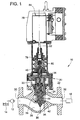
- FIG. 1 is a cross section of a valve assembly in accordance with an embodiment of the present invention, with a fuel metering application being indicated schematically.
- FIG. 2 is an enlarged portion of the cross section of the valve assembly shown in FIG. 1, with the valve illustrated in a closed position.
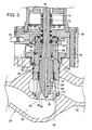
- FIG. 3 is cross section similar to FIG. 2, but with the valve shown in an open position.
- FIG. 1 an embodiment of the present invention has been illustrated as an electrically actuated valve assembly 10.
- An application or example working environment schematically shown in FIG. 1 is metering fuel flow in a turbine engine.
- a pump 12 pressurizes and pumps fuel (which may either be gaseous fuel or liquid fuel) from a fuel storage tank 14 to the turbine engine 16.
- the valve assembly 10 is interposed therebetween for controlling fuel flow to the engine 16.
- the valve assembly 10 includes a valve housing 20 that is adapted to pass the fluid to be regulated and provides the fluid chambers used for effecting the present invention.
- the valve housing comprises a valve body 22, a generally cylindrical valve cage 24, and a valve bonnet 26, however, it will be appreciated that other valve housing arrangements can be used as appropriate.
- the valve body 26 defines a flow passageway 28 with inlet and outlet ports 30, 32. Fuel or other appropriate fluid depending upon the application flows through the passageway 28 during operation, typically in one direction from the inlet port 30 to the outlet port 32.
- the valve cage 24 is mounted to the valve body 26 by a threaded retaining collar 33 screwed to valve body to provide a valve chamber along the flow passageway 28.
- the valve bonnet 26 is bolted onto the valve body 26 with spacers and provides a cylindrical bore for guiding valve stroke.
- the valve assembly 10 also includes a movable and generally cylindrical valve member 34 that is mounted for linear reciprocation in the valve housing 20.
- the valve member 34 includes a plug portion 38 for providing flow regulation and a stem portion 40 extending axially from the plug portion.
- the stem and plug portions may be formed as a unitary component or as separate component parts that may be secured together.
- the stem portion 40 extends from the valve housing 20 in order to be acted upon by a suitable actuator for positioning the plug portion 38 to regulate flow.
- the valve member 34 is movable toward and away from a ring shaped valve seat 42.
- the valve seat 42 is provided in the valve housing 20 between the valve body 22 and the valve cage 24 in a location that is coaxial about the valve axis 36 and that surrounds the flow passageway 28.
- the valve member has a fully open position as shown in FIG. 3, and a fully closed position in which the plug portion 38 is seated against the valve seat 42, and may include various intermediate positions therebetween. It should be noted that in the disclosed embodiment the fully open position as shown in FIG. 3 is not set by virtue of the valve member bottoming out, but is set externally through the actuator that includes a limit to limit how open the valve member can move. Thus, for all operating positions of the valve, an internal pressure passage 48, the significance of which is herein described, remains continuously open in the disclosed embodiment.
- the valve member 34 may include several sections of different diameters along its axial length.
- the plug portion 38 includes a cylindrical section with a cone shaped nose that provides a radially extending end face 44 and is adapted to seat against the valve seat 42.
- the stem portion 40 may be of a reduced diameter relative to the plug portion 38 to provide a radially extending shoulder 46 that is adapted to be acted upon by fluid pressure.
- the stem portion 40 may also be stepped to include additional different diameter portions as shown.
- the pressure passage 48 ports the pressure experienced at the end face 44 into an intermediate chamber 50 defined between the valve stem portion 42 and the valve cage 24, and also into the opposite end of a piston chamber 52, which may also be defined by the valve cage 24.
- the pressure passage 48 includes a first axially extending passage segment 54 formed through the movable valve member 34 and second axially extending passage segment formed through the cage 26 of the valve housing 20.
- the pressure passage 48 may be provided entirely through the movable valve member 34 or entirely through the valve housing 20 if desired in alternative embodiments of the present invention.
- the fluid pressure that is ported to the intermediate chamber 50 acts upon the working face that is provided by the annular shoulder 46 at the intersection of the valve stem portion 40 and the valve plug portion 38. This provides an axial force opposite the force generated by fluid pressure on the plug end face 44 and partially counterbalances the fluid pressure forces across the valve member 34.
- the effective working area of the annular shoulder 46 is less than the working area of the plug end face 44 due to the space occupied by the valve stem portion 40.
- the valve stem 40 projects axially and externally from the valve housing 20 and is therefore subjected to atmospheric fluid pressure (in addition to actuator and/or spring force when applied). Accordingly, because the fluid pressure at the plug end face 44 is typically substantially greater than atmospheric, the provision of the intermediate chamber 50 and the annular shoulder 46 is only partially effective in achieving the desired effect.
- the disclosed embodiment includes a piston 58 integral with the valve member 34 that includes a first side 60 subjected to the fluid pressure experienced at the plug end face 44, and a second side 62 subjected to a second pressure.
- this second pressure along the second side 62 of the piston is atmospheric pressure by virtue of a vent passage 64 that vents the lower part of the piston chamber 52 to ambient as a matter of simplicity for the disclosed application, although other pressures are possible (e.g. tank or sump pressure).
- an alternative embodiment of the present invention may eliminate the intermediate chamber 50 and the fluid pressure applied along the shoulder 46.
- the piston 58 compliments the shoulder 46 and serves the purpose of offsetting or counterbalancing the working area occupied by the valve stem portion 40.
- the effective working area of the of the first side 60 of the piston 58 may therefore be about equal to the largest diameter of the stem portion 40.
- a difference in working areas may be provided to substantially balance the valve while at the same time, providing a slight bias on the valve such as to maintain the valve in a closed (or open) position upon power loss, or to provide a force to counteract other flow forces or to balance spring forces, or for any such suitable balancing purpose.
- the piston 58 With the provision of the piston 58, however, the fluid pressure forces can more easily be controlled across the valve member 34 to provide a desired performance characteristic which has not been achieved in the prior art, such as reducing actuator force and/or improving dynamic performance.
- the integral piston 58 can either be unitarily formed into the valve stem portion 40, or as shown may be a separate component part secured to the valve member.
- the piston 58 is a separate ring shaped component with a central hole such that it is that is concentrically slid onto the valve stem portion 42 and secured thereon by a retaining mechanism.
- the retaining mechanism used in the disclosed embodiment is the combination of a shoulder 66 formed at a step in the stem portion 40 and a snap ring 68 that is installed into a groove on the valve stem portion 40.
- other integral connectors may be used such as a threaded connection, welding and the like that cause the piston to move with the valve member 34.
- Dynamic or static ring seals 70 as illustrated are strategically located in seal retaining grooves throughout the valve assembly 10 to provide sealing and to prevent passage of fluid between component parts.
- the operation of such seals will readily be appreciated by one of ordinary skill in the art upon viewing the drawings, and accordingly further description is not provided herein for purposes of brevity.
- leakage were to occur past any one of many of the seals 70 (particularly dynamic seals which are more prone to wear), such leakage paths lead to a common fugitive emission collection passage which happens to coincide with the piston chamber vent passage 64. This is particularly advantageous for gaseous fuels for which leakage problems may be hard to detect.
- the vent passage 64 leads to a fugitive emission port 74 that may be subjected to atmospheric pressure.
- the port 74 may be connected to a filter or screen to avoid plugging or dirt ingress, or for gaseous fuel applications an exhaust line leading to a remote safe exhaust port location for fugitive gas emissions, sensor equipment, or other apparatus.
- cylindrical wear rings/bushings 72 supported by the valve housing 20 are also provided in spaced axial relation along the valve member 34 to guide sliding movement of the valve member 34.
- the electrically actuated valve assembly 10 may also include as part of an overall support housing, not only the valve housing 20, but also a spring housing 76 and an actuator housing 78, as shown in FIG. 1. In an alternative embodiment, these structural components parts may not be needed or may also be integrated into the valve housing 20 which provides the various fluid chambers if desired.
- the spring housing 76 is mounted between the actuator housing 78 and the valve housing 20.
- the valve stem portion 40 extends through the valve bonnet 26 into the spring housing 76.
- the stem portion 40 may be biased by one or more springs 80 (e. g. it may be biased toward a closed, an open position, or may be unbiased), and is subjected to the driving force output 82 of an electrical actuator 84 contained in the actuator housing 78.
- An advantage that can be realized using the pressure balancing aspects of the present invention is that a lower power electrical actuator 84 may be used and/or dynamic performance can be increased.
- the piston 58 can be used to effectively reduce the pressure imbalance that would otherwise occur absent the piston 58 and if only partial counterbalance was provided via the pressure in intermediate chamber 50 acting upon shoulder 46.
- significant advantages are realized for electrical actuation applications, it will be appreciated that the invention may also be employed with other types of actuators including hydraulic actuation where an increase in dynamic performance or decrease in actuation force is desired or for other appropriate purposes.
Landscapes
- Engineering & Computer Science (AREA)
- General Engineering & Computer Science (AREA)
- Mechanical Engineering (AREA)
- Lift Valve (AREA)
- Fluid-Damping Devices (AREA)
- Fluid-Driven Valves (AREA)
Abstract
Description
Claims (21)
- A valve assembly, comprising:a housing having a valve chamber, a flow passageway extending through the valve chamber, and a piston chamber; anda valve member in the housing and movable along a valve axis, the valve member including a plug portion arranged along the flow passageway for regulating fluid flow therethrough, the plug portion subjected to a first pressure urging the valve in a first direction;a piston slidable in the piston chamber integral with the valve member, the piston having a first side subjected to the first pressure urging the valve in a second direction opposite said first direction and a second side subjected to a second pressure urging the valve in the first direction; anda pressure passage providing fluid pressure communication between the first side of the piston and the valve plug portion.
- The valve assembly of claim 1, wherein the pressure passage is defined at least in part internally through the valve member.
- The valve assembly of claim 1, wherein the valve member includes a valve stem portion having a diameter that is smaller than a diameter of the plug portion, wherein a radially extending working face is formed between the stem portion and plug portion, and wherein the working face is subjected to said first pressure urging the valve in said second direction.
- The valve assembly of claim 3, further comprising a vent passageway in fluidically connecting the piston chamber along said second side to the external atmosphere, whereby the second pressure is atmospheric pressure.
- The valve assembly of claim 3, wherein the valve stem portion includes a larger diameter portion and a smaller diameter portion, the piston being integral with the valve member along the smaller diameter portion.
- The valve assembly of claim 5, wherein the piston is formed separately of the valve member and includes a central hole receiving the valve stem portion therethrough, the piston being secured to the piston.
- The valve assembly of claim 1, further comprising an electrical actuator acting upon valve member in axially spaced relation to the plug portion for reciprocating the valve member along the valve axis.
- The valve assembly of claim 1, wherein the housing includes an annular valve seat coaxial about the valve axis and interposed on the flow passageway, the plug portion being movable toward and away from the seat between fully closed and open positions, and intermediate positions therebetween.
- The valve assembly of claim 1, wherein the valve member is a fuel metering valve that meters fuel flowing along the flow passageway to a turbine engine.
- The valve assembly of claim 1, wherein the pressure passage has a continuous open state for all operating positions of the valve member.
- The valve assembly of claim 1, wherein said housing comprises a valve housing and a spring housing mounted to the valve housing, the spring housing including at least one spring biasing the valve in a predetermined direction.
- The valve assembly of claim 11, wherein said housing includes an actuator housing comprising an electrical actuator mounted to the spring housing, the spring housing disposed between the electrical actuator and the valve housing.
- The valve assembly of claim 1, wherein the valve member includes a valve stem, the valve stem including a radially extending working surface area subject to atmospheric pressure, and wherein the second pressure is atmospheric fluid pressure, and wherein the second side of the piston has a radially extending working surface area that is sized relative to the working surface area of the valve stem to reduce actuation force needed for moving the valve member.
- The valve assembly of claim 13, wherein the radially extending working surface areas of the piston and the valve stem are about equal for substantially balancing fluid pressures axially across the valve member.
- The valve assembly of claim 1, wherein the valve housing comprises a valve body, a valve cage mounted in the valve body, and a valve bonnet mounted to the valve body, the valve member slidably engaging the valve cage, and wherein the pressure passage extends through the valve member into an intermediate chamber defined between the valve member and the valve cage and through an axially extending passage formed in the valve cage to the piston chamber, the piston chamber being defined in the valve cage, wherein fluid pressure in the intermediate portion axially urges the valve member in said second direction.
- A method of balancing fluid forces across a plug valve, comprising:regulating a flow of fluid along a flow passageway with a valve member, the valve member including a plug portion that is adapted to restrict flow and a valve stem, the fluid acting upon the plug portion and being at a first pressure to provide a first force urging the valve member in a first direction;actuating the valve stem to drive the valve member;counteracting at least part of the first force with a second force generated by a piston integral with the valve member and slidable in a piston chamber, the piston having a first side subjected to the first pressure and a second side vented to ambient; andcommunicating the first pressure from the flow passageway to the piston chamber on the first side.
- The method of claim 16, wherein said actuating comprises electrically actuating with an electrical actuator driving the valve member.
- The method of claim 16, wherein the first pressure applied to the first side urges the valve member in a second direction opposite said first direction.
- The method of claim 16, further comprising metering fuel flow in a turbine engine along the flow passageway with the plug portion.
- The method of claim 16, further comprising porting the first pressure to a radially extending working surface of the valve member, the first pressure acting upon the radially extending working surface separate from the piston to urge the valve member in a second direction opposite said first direction to further counteract said first force.
- The method of claim 16, wherein said porting the first pressure is conducted at least in part through an internal passage in the valve member and at least in part through a housing slidably engaging the valve member.
Applications Claiming Priority (2)
| Application Number | Priority Date | Filing Date | Title |
|---|---|---|---|
| US42303302P | 2002-11-01 | 2002-11-01 | |
| US423033P | 2002-11-01 |
Publications (3)
| Publication Number | Publication Date |
|---|---|
| EP1416206A2 true EP1416206A2 (en) | 2004-05-06 |
| EP1416206A3 EP1416206A3 (en) | 2004-08-04 |
| EP1416206B1 EP1416206B1 (en) | 2006-12-20 |
Family
ID=32094180
Family Applications (1)
| Application Number | Title | Priority Date | Filing Date |
|---|---|---|---|
| EP20030078416 Expired - Lifetime EP1416206B1 (en) | 2002-11-01 | 2003-10-30 | Valve having pressure balancing piston and method involving same |
Country Status (4)
| Country | Link |
|---|---|
| US (2) | US7000895B2 (en) |
| EP (1) | EP1416206B1 (en) |
| JP (1) | JP4485781B2 (en) |
| DE (1) | DE60310504T2 (en) |
Cited By (8)
| Publication number | Priority date | Publication date | Assignee | Title |
|---|---|---|---|---|
| CN102022555A (en) * | 2010-12-21 | 2011-04-20 | 中核新能核工业工程有限责任公司 | Nuclear electric torpedo vacuum valve |
| GB2480100A (en) * | 2010-05-07 | 2011-11-09 | Shako Co Ltd | High pressure solenoid valve |
| EP1818583A3 (en) * | 2006-02-08 | 2012-10-10 | Mocon, Inc. | A self-flushing needle valve |
| CN103090024A (en) * | 2011-10-27 | 2013-05-08 | 株式会社鹭宫制作所 | Electric valve |
| CN103711914A (en) * | 2012-09-28 | 2014-04-09 | 艾默生过程管理调节技术公司 | Balance valve for fluid regulator |
| US9080994B2 (en) | 2012-10-11 | 2015-07-14 | Mocon, Inc. | Analyte sensor with spent gas flushed endcaps |
| WO2015167422A1 (en) * | 2014-04-28 | 2015-11-05 | Moog Inc. | Turbine combustion chamber pressure assisted control valve |
| CN109630697A (en) * | 2017-10-09 | 2019-04-16 | 大力士股份有限公司 | Poppet and component for poppet |
Families Citing this family (27)
| Publication number | Priority date | Publication date | Assignee | Title |
|---|---|---|---|---|
| US7066444B2 (en) * | 2004-02-05 | 2006-06-27 | Fmc Technologies, Inc. | Pressure balanced fluid control device |
| GB0503101D0 (en) * | 2005-02-15 | 2005-03-23 | Xamol Ltd | Valve assembly |
| JP2007078092A (en) * | 2005-09-15 | 2007-03-29 | Miura Co Ltd | Valve |
| US8123309B2 (en) * | 2007-10-23 | 2012-02-28 | New York Air Brake Corporation | Dual seal brake control valve |
| DE102009004803A1 (en) * | 2008-01-17 | 2009-07-23 | Eto Magnetic Gmbh | Electromagnetically actuated valve device |
| US8272399B2 (en) * | 2008-06-13 | 2012-09-25 | Woodward, Inc. | Fluid admission system for providing a pressure-balanced valve |
| EP2350506B8 (en) * | 2008-11-26 | 2012-11-28 | Parker Hannifin Manufacturing Germany GmbH & Co. KG | Hydraulic valve assembly having a cartridge insert valve exhibiting a closing element arranged in a pressure equalized manner |
| US8038121B2 (en) * | 2009-01-06 | 2011-10-18 | Woodward, Inc. | Fluid control valve with sensing port |
| AU2010210501B2 (en) | 2009-02-05 | 2014-02-20 | Flowserve Pte. Ltd. | Pressure-balanced control valves |
| CN101705871B (en) * | 2009-11-20 | 2012-05-09 | 株洲南方燃气轮机成套制造安装有限公司 | Gas fuel regulating valve of gas turbine |
| DE102010037011B4 (en) * | 2010-08-16 | 2013-12-24 | Samson Ag | Actuator for controlling a fluid flow |
| US9086702B2 (en) | 2011-07-01 | 2015-07-21 | Emerson Process Management Regulator Technologies, Inc. | Pressure-balanced fluid pressure regulators |
| CN107076312B (en) * | 2014-11-29 | 2019-07-12 | 航天喷气发动机洛克达因股份有限公司 | Valve assembly with electronic control |
| US10030779B2 (en) * | 2015-09-18 | 2018-07-24 | Hamilton Sundstrand Corporation | Metering devices |
| US20170082035A1 (en) * | 2015-09-21 | 2017-03-23 | Moog Inc. | Gas turbine active combustion instability control system |
| US10458293B2 (en) | 2017-07-20 | 2019-10-29 | Woodward, Inc. | Metering plate for reduction in discharge coefficient variation between gaseous fuel injectors |
| WO2019152263A1 (en) * | 2018-01-30 | 2019-08-08 | Fisher Controls International Llc | Balanced trim regulator |
| DE102018102251A1 (en) * | 2018-02-01 | 2019-08-01 | Samson Aktiengesellschaft | Valve body modular system and lift valve |
| IT201900003389A1 (en) * | 2019-03-08 | 2020-09-08 | Giacomini Spa | CARTRIDGE REGULATION GROUP WITH COMPENSATION CHAMBER AND HYDRAULIC VALVE INCLUDING THE CARTRIDGE REGULATION GROUP. |
| IT201900003433A1 (en) * | 2019-03-08 | 2020-09-08 | Giacomini Spa | CARTRIDGE ADJUSTMENT UNIT AND HYDRAULIC VALVE WITH DOUBLE FLOW ADJUSTMENT SCALE. |
| DE102020210248B4 (en) | 2020-08-12 | 2024-09-26 | Moog Luxembourg S.à.r.l. | Hydraulic built-in valve |
| CN114321409A (en) * | 2020-09-30 | 2022-04-12 | 阳泉市勤工技术实业开发有限公司 | Self-balancing micro-force switch valve |
| US20230417341A1 (en) | 2020-11-13 | 2023-12-28 | Asco Sas | Valve system |
| US12222039B2 (en) * | 2021-03-22 | 2025-02-11 | Ichor Systems, Inc. | Guided flow valve assembly and system incorporating same |
| US11988288B2 (en) * | 2021-04-27 | 2024-05-21 | Swagelok Company | Poppet-style valve arrangements |
| US11906063B2 (en) | 2022-01-21 | 2024-02-20 | Hamilton Sundstrand Corporation | Pressure actuated switching valve |
| CN121876207A (en) * | 2026-03-20 | 2026-04-17 | 大连大高阀门股份有限公司 | Main valve for pilot-operated safety valve |
Family Cites Families (7)
| Publication number | Priority date | Publication date | Assignee | Title |
|---|---|---|---|---|
| US2758812A (en) * | 1951-01-05 | 1956-08-14 | Kellogg M W Co | Pilot operated fuel control valve for gas turbines |
| DE1025693B (en) | 1953-04-02 | 1958-03-06 | Erich Herion | Electromagnetically controlled three-way valve with relief means |
| US2897836A (en) | 1956-06-13 | 1959-08-04 | Us Industries Inc | Balanced valve |
| US3318577A (en) | 1965-05-24 | 1967-05-09 | George W Banks | High pressure valve having soft seating and balanced seal |
| US4341370A (en) | 1980-11-20 | 1982-07-27 | Banks George W | High pressure, three stage, balanced valve |
| US5086808A (en) * | 1990-12-07 | 1992-02-11 | Cooper Industries, Inc. | Balanced sleeve control choke |
| US5386965A (en) | 1993-06-04 | 1995-02-07 | Ber-Lo Manufacturing Company, Inc. | High pressure flow valve with pressure assist valve seal |
-
2003
- 2003-10-28 US US10/695,403 patent/US7000895B2/en not_active Expired - Lifetime
- 2003-10-30 EP EP20030078416 patent/EP1416206B1/en not_active Expired - Lifetime
- 2003-10-30 JP JP2003371325A patent/JP4485781B2/en not_active Expired - Fee Related
- 2003-10-30 DE DE2003610504 patent/DE60310504T2/en not_active Expired - Lifetime
-
2005
- 2005-07-27 US US11/191,098 patent/US7051746B2/en not_active Expired - Lifetime
Cited By (13)
| Publication number | Priority date | Publication date | Assignee | Title |
|---|---|---|---|---|
| EP1818583A3 (en) * | 2006-02-08 | 2012-10-10 | Mocon, Inc. | A self-flushing needle valve |
| GB2480100A (en) * | 2010-05-07 | 2011-11-09 | Shako Co Ltd | High pressure solenoid valve |
| GB2480100B (en) * | 2010-05-07 | 2012-03-21 | Shako Co Ltd | Armature assembly of a high pressure solenoid valve |
| CN102022555B (en) * | 2010-12-21 | 2012-06-27 | 中核新能核工业工程有限责任公司 | Nuclear electric torpedo vacuum valve |
| CN102022555A (en) * | 2010-12-21 | 2011-04-20 | 中核新能核工业工程有限责任公司 | Nuclear electric torpedo vacuum valve |
| CN103090024B (en) * | 2011-10-27 | 2014-08-06 | 株式会社鹭宫制作所 | Electric valve |
| CN103090024A (en) * | 2011-10-27 | 2013-05-08 | 株式会社鹭宫制作所 | Electric valve |
| CN103711914A (en) * | 2012-09-28 | 2014-04-09 | 艾默生过程管理调节技术公司 | Balance valve for fluid regulator |
| US9080994B2 (en) | 2012-10-11 | 2015-07-14 | Mocon, Inc. | Analyte sensor with spent gas flushed endcaps |
| WO2015167422A1 (en) * | 2014-04-28 | 2015-11-05 | Moog Inc. | Turbine combustion chamber pressure assisted control valve |
| CN109630697A (en) * | 2017-10-09 | 2019-04-16 | 大力士股份有限公司 | Poppet and component for poppet |
| EP3470712A1 (en) * | 2017-10-09 | 2019-04-17 | Samson Aktiengesellschaft | Poppet valve and arrangement for a poppet valve |
| CN109630697B (en) * | 2017-10-09 | 2020-07-31 | 大力士股份有限公司 | Poppet valve and assembly for a poppet valve |
Also Published As
| Publication number | Publication date |
|---|---|
| EP1416206B1 (en) | 2006-12-20 |
| US7000895B2 (en) | 2006-02-21 |
| US20050279959A1 (en) | 2005-12-22 |
| US20040099832A1 (en) | 2004-05-27 |
| DE60310504D1 (en) | 2007-02-01 |
| JP2004162918A (en) | 2004-06-10 |
| US7051746B2 (en) | 2006-05-30 |
| EP1416206A3 (en) | 2004-08-04 |
| JP4485781B2 (en) | 2010-06-23 |
| DE60310504T2 (en) | 2007-10-11 |
Similar Documents
| Publication | Publication Date | Title |
|---|---|---|
| US7000895B2 (en) | Valve having pressure balancing piston and method involving same | |
| US6354319B1 (en) | Low differential, pilot operated fluid pressure regulation apparatus and method | |
| US20080196773A1 (en) | Ventline control valve assembly | |
| CN101361032B (en) | Pressure regulator with cowling | |
| US8074999B2 (en) | Dynamic sealing arrangement for movable shaft | |
| EP1303718B1 (en) | Pressure regulating piston with built in relief valve | |
| US5076765A (en) | Shaft seal arrangement of turbocharger | |
| EP2373910B1 (en) | Fluid control valve | |
| US9791067B2 (en) | Flare tip valve dampening | |
| EP1126186B1 (en) | Modular, compliant sealing bearing assembly | |
| US7862048B2 (en) | Gasket for a valve in an internal combustion engine | |
| US9080687B2 (en) | Pressure and flow altitude compensated shutoff valve | |
| EP2836774B1 (en) | Pilot operated valve | |
| CN114729601B (en) | Fuel nozzle with reduced flow tolerance | |
| US9404513B2 (en) | Servo valve | |
| JP2006529017A (en) | valve | |
| US7322373B2 (en) | High accuracy low leakage valve for high pressure applications | |
| US5195556A (en) | Pressure relief valve | |
| KR102744357B1 (en) | Capacity control valve | |
| CN213685321U (en) | Electromagnetic valve | |
| CN222102431U (en) | Relief valve | |
| EP4244511B1 (en) | Valve system | |
| US6676386B2 (en) | Oilless air motor assembly for hydraulic pumps | |
| CN1281944A (en) | Valve assembly for vehicle gas cylinder | |
| TW202548159A (en) | Actuators and valves |
Legal Events
| Date | Code | Title | Description |
|---|---|---|---|
| PUAI | Public reference made under article 153(3) epc to a published international application that has entered the european phase |
Free format text: ORIGINAL CODE: 0009012 |
|
| AK | Designated contracting states |
Kind code of ref document: A2 Designated state(s): AT BE BG CH CY CZ DE DK EE ES FI FR GB GR HU IE IT LI LU MC NL PT RO SE SI SK TR |
|
| AX | Request for extension of the european patent |
Extension state: AL LT LV MK |
|
| PUAL | Search report despatched |
Free format text: ORIGINAL CODE: 0009013 |
|
| AK | Designated contracting states |
Kind code of ref document: A3 Designated state(s): AT BE BG CH CY CZ DE DK EE ES FI FR GB GR HU IE IT LI LU MC NL PT RO SE SI SK TR |
|
| AX | Request for extension of the european patent |
Extension state: AL LT LV MK |
|
| 17P | Request for examination filed |
Effective date: 20041122 |
|
| AKX | Designation fees paid |
Designated state(s): DE GB |
|
| 17Q | First examination report despatched |
Effective date: 20050331 |
|
| GRAP | Despatch of communication of intention to grant a patent |
Free format text: ORIGINAL CODE: EPIDOSNIGR1 |
|
| GRAS | Grant fee paid |
Free format text: ORIGINAL CODE: EPIDOSNIGR3 |
|
| GRAA | (expected) grant |
Free format text: ORIGINAL CODE: 0009210 |
|
| AK | Designated contracting states |
Kind code of ref document: B1 Designated state(s): DE GB |
|
| REG | Reference to a national code |
Ref country code: GB Ref legal event code: FG4D |
|
| REF | Corresponds to: |
Ref document number: 60310504 Country of ref document: DE Date of ref document: 20070201 Kind code of ref document: P |
|
| PLBE | No opposition filed within time limit |
Free format text: ORIGINAL CODE: 0009261 |
|
| STAA | Information on the status of an ep patent application or granted ep patent |
Free format text: STATUS: NO OPPOSITION FILED WITHIN TIME LIMIT |
|
| 26N | No opposition filed |
Effective date: 20070921 |
|
| PGFP | Annual fee paid to national office [announced via postgrant information from national office to epo] |
Ref country code: DE Payment date: 20121029 Year of fee payment: 10 |
|
| PGFP | Annual fee paid to national office [announced via postgrant information from national office to epo] |
Ref country code: GB Payment date: 20121025 Year of fee payment: 10 |
|
| GBPC | Gb: european patent ceased through non-payment of renewal fee |
Effective date: 20131030 |
|
| PG25 | Lapsed in a contracting state [announced via postgrant information from national office to epo] |
Ref country code: GB Free format text: LAPSE BECAUSE OF NON-PAYMENT OF DUE FEES Effective date: 20131030 |
|
| REG | Reference to a national code |
Ref country code: DE Ref legal event code: R119 Ref document number: 60310504 Country of ref document: DE Effective date: 20140501 |
|
| PG25 | Lapsed in a contracting state [announced via postgrant information from national office to epo] |
Ref country code: DE Free format text: LAPSE BECAUSE OF NON-PAYMENT OF DUE FEES Effective date: 20140501 |