EP1416149A2 - Air cleaner system for motorcycle - Google Patents
Air cleaner system for motorcycle Download PDFInfo
- Publication number
- EP1416149A2 EP1416149A2 EP04001987A EP04001987A EP1416149A2 EP 1416149 A2 EP1416149 A2 EP 1416149A2 EP 04001987 A EP04001987 A EP 04001987A EP 04001987 A EP04001987 A EP 04001987A EP 1416149 A2 EP1416149 A2 EP 1416149A2
- Authority
- EP
- European Patent Office
- Prior art keywords
- air cleaner
- head box
- air
- intake
- intake passages
- Prior art date
- Legal status (The legal status is an assumption and is not a legal conclusion. Google has not performed a legal analysis and makes no representation as to the accuracy of the status listed.)
- Granted
Links
Images


Classifications
-
- F—MECHANICAL ENGINEERING; LIGHTING; HEATING; WEAPONS; BLASTING
- F02—COMBUSTION ENGINES; HOT-GAS OR COMBUSTION-PRODUCT ENGINE PLANTS
- F02M—SUPPLYING COMBUSTION ENGINES IN GENERAL WITH COMBUSTIBLE MIXTURES OR CONSTITUENTS THEREOF
- F02M35/00—Combustion-air cleaners, air intakes, intake silencers, or induction systems specially adapted for, or arranged on, internal-combustion engines
- F02M35/10—Air intakes; Induction systems
- F02M35/10006—Air intakes; Induction systems characterised by the position of elements of the air intake system in direction of the air intake flow, i.e. between ambient air inlet and supply to the combustion chamber
- F02M35/10013—Means upstream of the air filter; Connection to the ambient air
-
- F—MECHANICAL ENGINEERING; LIGHTING; HEATING; WEAPONS; BLASTING
- F02—COMBUSTION ENGINES; HOT-GAS OR COMBUSTION-PRODUCT ENGINE PLANTS
- F02M—SUPPLYING COMBUSTION ENGINES IN GENERAL WITH COMBUSTIBLE MIXTURES OR CONSTITUENTS THEREOF
- F02M35/00—Combustion-air cleaners, air intakes, intake silencers, or induction systems specially adapted for, or arranged on, internal-combustion engines
- F02M35/02—Air cleaners
- F02M35/04—Air cleaners specially arranged with respect to engine, to intake system or specially adapted to vehicle; Mounting thereon ; Combinations with other devices
-
- F—MECHANICAL ENGINEERING; LIGHTING; HEATING; WEAPONS; BLASTING
- F02—COMBUSTION ENGINES; HOT-GAS OR COMBUSTION-PRODUCT ENGINE PLANTS
- F02M—SUPPLYING COMBUSTION ENGINES IN GENERAL WITH COMBUSTIBLE MIXTURES OR CONSTITUENTS THEREOF
- F02M35/00—Combustion-air cleaners, air intakes, intake silencers, or induction systems specially adapted for, or arranged on, internal-combustion engines
- F02M35/10—Air intakes; Induction systems
- F02M35/10006—Air intakes; Induction systems characterised by the position of elements of the air intake system in direction of the air intake flow, i.e. between ambient air inlet and supply to the combustion chamber
- F02M35/10026—Plenum chambers
- F02M35/10039—Intake ducts situated partly within or on the plenum chamber housing
-
- F—MECHANICAL ENGINEERING; LIGHTING; HEATING; WEAPONS; BLASTING
- F02—COMBUSTION ENGINES; HOT-GAS OR COMBUSTION-PRODUCT ENGINE PLANTS
- F02M—SUPPLYING COMBUSTION ENGINES IN GENERAL WITH COMBUSTIBLE MIXTURES OR CONSTITUENTS THEREOF
- F02M35/00—Combustion-air cleaners, air intakes, intake silencers, or induction systems specially adapted for, or arranged on, internal-combustion engines
- F02M35/10—Air intakes; Induction systems
- F02M35/10242—Devices or means connected to or integrated into air intakes; Air intakes combined with other engine or vehicle parts
- F02M35/10262—Flow guides, obstructions, deflectors or the like
-
- F—MECHANICAL ENGINEERING; LIGHTING; HEATING; WEAPONS; BLASTING
- F02—COMBUSTION ENGINES; HOT-GAS OR COMBUSTION-PRODUCT ENGINE PLANTS
- F02M—SUPPLYING COMBUSTION ENGINES IN GENERAL WITH COMBUSTIBLE MIXTURES OR CONSTITUENTS THEREOF
- F02M35/00—Combustion-air cleaners, air intakes, intake silencers, or induction systems specially adapted for, or arranged on, internal-combustion engines
- F02M35/16—Combustion-air cleaners, air intakes, intake silencers, or induction systems specially adapted for, or arranged on, internal-combustion engines characterised by use in vehicles
- F02M35/162—Motorcycles; All-terrain vehicles, e.g. quads, snowmobiles; Small vehicles, e.g. forklifts
-
- F—MECHANICAL ENGINEERING; LIGHTING; HEATING; WEAPONS; BLASTING
- F02—COMBUSTION ENGINES; HOT-GAS OR COMBUSTION-PRODUCT ENGINE PLANTS
- F02B—INTERNAL-COMBUSTION PISTON ENGINES; COMBUSTION ENGINES IN GENERAL
- F02B61/00—Adaptations of engines for driving vehicles or for driving propellers; Combinations of engines with gearing
- F02B61/02—Adaptations of engines for driving vehicles or for driving propellers; Combinations of engines with gearing for driving cycles
-
- F—MECHANICAL ENGINEERING; LIGHTING; HEATING; WEAPONS; BLASTING
- F02—COMBUSTION ENGINES; HOT-GAS OR COMBUSTION-PRODUCT ENGINE PLANTS
- F02M—SUPPLYING COMBUSTION ENGINES IN GENERAL WITH COMBUSTIBLE MIXTURES OR CONSTITUENTS THEREOF
- F02M35/00—Combustion-air cleaners, air intakes, intake silencers, or induction systems specially adapted for, or arranged on, internal-combustion engines
- F02M35/02—Air cleaners
-
- Y—GENERAL TAGGING OF NEW TECHNOLOGICAL DEVELOPMENTS; GENERAL TAGGING OF CROSS-SECTIONAL TECHNOLOGIES SPANNING OVER SEVERAL SECTIONS OF THE IPC; TECHNICAL SUBJECTS COVERED BY FORMER USPC CROSS-REFERENCE ART COLLECTIONS [XRACs] AND DIGESTS
- Y02—TECHNOLOGIES OR APPLICATIONS FOR MITIGATION OR ADAPTATION AGAINST CLIMATE CHANGE
- Y02T—CLIMATE CHANGE MITIGATION TECHNOLOGIES RELATED TO TRANSPORTATION
- Y02T10/00—Road transport of goods or passengers
- Y02T10/10—Internal combustion engine [ICE] based vehicles
- Y02T10/12—Improving ICE efficiencies
Definitions
- the present invention relates to an air cleaner system for a motorcycle, which is disposed under a fuel tank, and particularly to an air cleaner system capable of making an air cleaner having a large capacity as compact as possible.
- a motorcycle including an air cleaner disposed between a fuel tank supported over a body frame and an engine supported under the body frame has been known, for example, from Japanese Patent Laid-open No. Hei 8-216958 and Japanese Patent Laid-open No. Hei 10-196478.
- the air cleaner disposed in the former document has a configuration in which a flat air cleaner element is disposed in the vertical direction, and the air cleaner disposed in the latter document has a configuration in which a cylindrical air cleaner element is also disposed in the vertical direction.
- an object of the present invention is to solve the above-described problem of the prior art air cleaner.
- an air cleaner system for a motorcycle in which an air cleaner is disposed between a fuel tank supported over a body frame and an engine supported under the body frame, characterized in that a plurality of independent air cleaner elements are disposed sideways in a case of the air cleaner.
- a dirty room provided in the case of the air cleaner is partitioned into a plurality of independent intake passages which are each connected to the corresponding one of the air cleaner elements; and part of each of wall surfaces for partitioning the dirty room into the plurality of intake passages is taken as a water drip wall projecting in the intake passage.
- ribs are formed on the water drip wall in such a manner as to project in the intake passage.
- an air cleaner element is divided into a plurality of independent parts disposed sideways, it is possible to efficiently dispose the air cleaner element in the case while ensuring a necessary filtering area.
- the capacity of the air cleaner can be increased without increasing the size of the air cleaner, so that it is possible to prevent the fuel tank positioned over the air cleaner from being affected by the mounting of the air cleaner, for example, it is not required to reduce the capacity of the fuel tank or to make the mounting position of the fuel tank higher.
- the dirty room provided in the case of the air cleaner is partitioned into a plurality of intake passages which are each connected to the corresponding one of the air cleaner elements, and part of each of wall surfaces for partitioning the dirty room into the plurality of intake passages is taken as a water drip wall projecting in the intake passage, and accordingly, at least part of outside air having entered the intake passage can be brought into contact with the water drip wall, and since the water drip wall projects in the intake passage, moisture in the outside air can be separated from the outside air by the contact therebetween. Accordingly, it is possible to effectively remove the moisture in outside air on the upstream side from the air cleaner elements.
- the ribs projecting in the intake passage are provided on the water drip wall, they function as baffle plates against outside air having entered in the intake passage. As a result, it is possible to further effectively remove moisture in outside air in addition to the presence of the water drip walls.
- Figs. 1 and 8 show a first embodiment.
- a body frame includes a head box 1 and a pair of main frames 2 branched from the head box 1 and extending rearwardly therefrom nearly in parallel to each other.
- Each of the head box 1 and the main frames 2 is made from a suitable material such as an aluminum alloy.
- the head box 1 is formed into a hollow shape by casing, and the main frame 2 is formed into a hollow shape by a suitable process such as extrusion.
- the front end of the head box 1 is connected to the rear end of a hollow intake duct 3 extending in the longitudinal direction while passing through the center line of the vehicular body.
- the intake duct 3 is made from, typically, a glass fiber reinforced resin.
- the front end of the intake duct 3 is connected to an outside air inlet 5.
- the outside air inlet 5 is opened in a nose portion 4a provided at the central portion of the front surface of an upper cowl 4 which is part of the cowling for covering the front body.
- the nose portion 4a is the foremost portion of the upper cowl 4 for covering the front portion of the head box 1.
- the nose portion 4a has the above-described outside air inlet 5 and a pair of headlamp openings 6 positioned on right and left sides of the outside air inlet 5.
- a headlamp 7 is supported by a headlamp stay 8 provided on each of the right and left side surfaces of the intake duct 3 in a state in which a front lens portion is fitted in the headlamp opening 6. It should be noted that the headlamp 7 is not only supported by the headlamp stay 8 but also supported at three points by the upper cowl 4.
- various stays have been provided separately from an intake duct; however, since the intake duct 3 in this embodiment is made from the glass fiber reinforced resin having a relatively high rigidity, various stays can be collectively integrally provided on the intake duct 3.
- One cowling stay 9 is integrally provided on the upper portion of the front end of the intake duct 3, which stay is connected to a central portion, over the outside air inlet 5, of the nose portion 4a, to support the upper cowl 4 at one point; and three instrument stays 10 are integrally provided on the intake duct 3 at positions behind the cowling stay 9, to support an instrument panel 11 at three points.
- the head box 1 integrally includes a main body 12 extending longer in straight line in the longitudinal direction while passing through the center line of the vehicular body, and right and left arms 13 branched from the rear end of the main body 12.
- the head box 1 is formed into an approximately Y-shape in a plan view as a whole.
- a front end portion 12a of the main body 12 is an opening portion tilted in a forward arrow shape.
- the rear end of the intake duct 3 is inserted in the opening portion, that is, the front end portion 12a, and is connected thereto by bolts 15.
- the rear end of the intake duct 3 inserted in the front end portion 12a of the main body 12 is fastened to mounting portions 14 formed on the right and left edges of the front end portion 12a by means of the bolts 15.
- a hollow columnar portion 16 having a vane-shaped cross-section is provided in the main body 12 at an approximately central portion in the lateral direction in such a manner as to be put between upper and lower walls of the main body 12.
- the hollow columnar portion 16 has at its central portion a through-hole 17 passing through the upper and lower walls of the main body 12.
- a handlebar steering shaft 18 passes through the through-hole 17 in the vertical direction and is turnably supported by bearings provided at upper and lower ends of the hollow columnar portion 16.
- the hollow columnar portion 16 is disposed in the central portion of the passage of the main body 12 with its major axis directed in the longitudinal direction, to thereby divide each of a space 12b and a space 13a near the hollow columnar portion 16 in the main body 12 into right and left parts (see Figs. 4).
- the rear end of the inside of the main body 12 is connected to the space 13a longer in the lateral direction in the arms 13.
- the rear end of the space 13a is closed with a rear wall 19 of the head box 1, and the space 13 is communicated to an air cleaner 21 through right and left openings 19a formed in the rear wall 19.
- the air cleaner 21 is disposed in a space which is surrounded by the right and left main frames 2 and which is positioned behind the head box 1, and is adapted to supply of new air in a down draft into respective cylinders of a V-type four-cycle engine 22 disposed under the air cleaner 21.
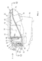
- Fig. 5 is a side view, with parts partially cutaway, of an essential portion of the front body, showing the layout of the fuel tank and the air cleaner;
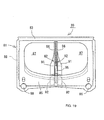
- Fig. 6 is a front view of the air cleaner;
- Fig. 7 is a perspective view of a member for mounting the air cleaner element.
- the air cleaner 21 includes a common case main body 26, and two independent cylindrical air cleaner elements 23 and 24 disposed in the case main body 26.
- the air cleaner elements 23 and 24 suck outside air from the head box 1 side through intake passages A and B provided in the front portion of the case main body 26, respectively.
- the inside of the case main body 26 is partitioned into a dirty room on the front side and a clean room C on the rear side.
- the dirty room is partitioned by a pair of water drip walls 25 into the left intake passage A and the right intake passage B, as seen along the running direction of the vehicular body.
- the clean room C houses the air cleaner elements 23 and 24. Further, intake pipes 27 and 28 are opened in the clean room C.
- the air cleaner elements 23 and 24, each having a relatively large capacity, are arranged in parallel to each other in the lateral direction.
- the air cleaner elements 23 and 24 are tilted slightly upwardly and downwardly, respectively in such a manner that both the rear ends thereof are close to each other.
- the tilting arrangement of the air cleaner elements 23 and 24 is based on the case shape of the air cleaner 21 which is wider on its front side.
- the air cleaner elements 23 and 24, which are tilted in matching to the shape of the air cleaner 21, can be housed in the air cleaner 21 with a high space efficiency.
- the case shape of the air cleaner 21 is determined on the basis of a space surrounded by the right and left main frames 2 and the head box 1.
- the rear side intake pipe 28 is opened upwardly at a position near the rear ends, closed to each other, of the air cleaner elements 23 and 24.
- the front side intake pipe 27 is similarly opened upwardly at a position near the front ends, apart from each other, of the air cleaner elements 23 and 24.
- the front side intake pipe 27 is surrounded by the pair of right and left water drip walls 25.
- the water drip walls 25 are integrally formed on the bottom of the case main body 26 of the air cleaner 21. As is apparent from Fig. 4, each of the water drip walls 25 is bent into an approximately V-shape projecting in the intake passage A or B.
- the intake passages A and B on the front side of the case main body 26 are opened, and the opened portions of the intake passages A and B are communicated to communication ports 29a formed in the front surface of a front cover 29 covered on the case main body 26 (see Fig. 6).
- the communication ports 29a are communicated to openings 19a formed in the rear wall 19 of the head box 1 (see Fig. 4).
- Right and left drain holes 29b opened forwardly are formed in a lower portion of the front surface of the front cover 29 (see Fig. 6).
- the rear ends of the water drip walls 25 are continuous to bulkheads in which the front ends of the air cleaner elements 23 and 24 are fitted.
- the front ends of the water drip walls 25 form a central partition 25a formed into a vertical column shape.
- the central partition 25a is connected to a front cover bulkhead 29c raised in the vertical direction at the central portion between the right and left communication ports 29a.
- the front cover bulkhead 29c extends rearwardly from the rear end of the hollow columnar portion 16 and is connected to a partition member 20 for partitioning the space 13 into right and left parts.
- These intake passages A and B which form the dirty room on the front side of the case main body 26 while being separated from each other by the water drip walls 25, are connected to the air cleaner elements 23 and 24, respectively.
- the water drip walls 25, which separate the intake passages A and B from each other, also separate the intake passages A and B on the dirty room side from the front side intake pipe 27 opened upwardly to the bottom of the clean room C.
- the stay 40 includes a lower plate 42 projecting from a frame 41 of the air cleaner element and an upper plate 43 obliquely overlapped on the lower plate 42.
- One end of the upper plate 43 is welded to a portion, positioned over the lower plate 42, of the frame 41, and the other end of the upper plate 43 is overlapped to the projecting end of the lower plate 42 and welded thereto.
- a bolt hole 44 is formed in a central portion of the upper plate 43.
- a flanged bolt 45 is inserted in the bolt hole 44 in such a manner that the upper end of a long head 46 of the flanged bolt 45 projects from the bolt hole 44.
- the upper end of the head 46 of the flanged bolt 45 has a driver groove 47 for allowing an operator to fasten the flanged bolt 45 by using a driver (not shown) with its end inserted in the driver groove 47.
- a flange 48 provided at the lower end of the head 46 of the flanged bolt 45 is abutted against the lower plate 42.
- the diameter of the flange 48 is larger than each of the diameter of a through-hole 42a formed in the lower plate 42 and the diameter of the bolt hole 44 for preventing the falling of the flanged bolt 45.
- a threaded portion 49 projecting downwardly from the head 46 is screwed in a threaded hole 51 of a boss 50 integrally formed on the bottom of the case main body 26. In this way, the air cleaner elements 23 and 24 are fixed to the case main body 26. With this configuration, the flanged bolt 45 is advantageously prevented from being fallen from the bolt hole 44 of the upper plate 43 and the through-hole 42a of the lower plate 42.
- the upper side of the air cleaner 21 is covered with a fuel tank 30.
- a raised bottom portion 31 of the fuel tank 30, positioned over the air cleaner 21, is raised in order to ensure, under the raised bottom portion 31, a sufficient space in which the air cleaner 21 is disposed.
- a rear portion of the fuel tank 30 extends rearwardly passing the rear ends of the main frames 2, to form an extension portion 32.
- the extension portion 32 is disposed between a pair of seat rails 33 extending obliquely upwardly, rearwardly from the rear ends of the right and left main frames 2 in such a manner that the rear end portion of the extension portion 32 extends under a seat 34 supported by the seat rails 33.
- the engine 22 has a front cylinder 35 and a rear cylinder 36. Air is sucked from the clean room C (see Fig. 4) of the air cleaner 21 into intake ports of the front and rear cylinders 35 and 36 in a down draft through the front side intake pipe 27 and the rear side intake pipe 28, respectively. In this embodiment, a space around the air cleaner elements 23 and 24 in the air cleaner 21 forms the clean room C having a large capacity.
- the air cleaner elements 23 and 24 are disposed in parallel to each other and are independently connected to the intake passages A and B as shown in Fig. 4, it is possible to sufficiently ensure the filtering area of the air cleaner 21, even if the air cleaner 21 is required to have a large capacity, by adding the filtering areas of the air cleaner elements 23 and 24 to each other.
- the air cleaner element in this embodiment is divided into the independent air cleaner elements 23 and 24, as compared with the case of providing a single large-sized air cleaner element, the air cleaner element in this embodiment, which is divided into the air cleaner elements 23 and 24, can be more efficiently disposed in the case main body 26 of the air cleaner 21 whose shape is restricted, to thereby make the air cleaner 21 compact while sufficiently ensuring the capacity of the air cleaner 21.
- the air cleaner 21 having a large capacity can be disposed under the fuel tank 30 without changing the capacity and the mounting height of the fuel tank 30, with a result that the degree of freedom in layout of the vehicular body can be enhanced. Since the intake passages A and B are directed to the hollow columnar portion 16, the flow of outside air, which is split right and left at the hollow columnar portion and is directed obliquely rearwardly, can be smoothly introduced in the air cleaner elements 23 and 24. As a result, it is possible to improve the intake efficiency of outside air.
- the dirty room provided in the case main body 26 of the air cleaner 21 is partitioned into the independent intake passages A and B connected to the corresponding air cleaner elements 23 and 24 and part of the wall for partitioning the intake passages A and B is taken as the water drip walls 25 projecting in the intake passages A and B, at least part of outside air having entered the intake passages A and B can be brought into contact with the water drip walls 25.
- the water drip walls 25 each having an approximately V-shape in the top view project in the intake passages A and B, moisture in the outside air can be easily separated from the outside air by the contact therebetween and the moisture thus separated can be discharged to the outside through the drain holes 29b.
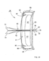
- Fig. 9 is a side view of a case main body 26 of an air cleaner 21 in this embodiment, wherein the side shape of the case main body 26 is shown by a solid line and other parts are shown by a virtual line;
- Fig. 10 is a front view, similar to Fig. 6, of the air cleaner 21 as seen along the direction A of Fig. 9;
- Fig. 11 is a top view of the case main body 26;
- Fig. 12 is a sectional view taken on line 12-12 of Fig. 9.
- water drip walls 25 formed on a front portion of the case main body 26 for partitioning intake passages A and B include a ceiling portion 60 and side walls 61 which are formed into a box-shape. An opening of an intake pipe 27 is covered with the box-like ceiling portion 60 and the side walls 61. A plurality of ribs 62 extending in the vertical direction are integrally formed on a surface, facing to each of the intake passages A and B, of the side wall 61.
- the lower end of the side wall 61 is continuous to a stepped portion 64 which is higher than a bottom wall 63, on the front side of the case main body 26, on which the intake passages A and B and the water drip walls 25 are formed.
- the stepped portion 64 is tilted both in the forward direction and in the lateral direction, and is continuous to the common surface of the bottom wall 63 lower than the stepped portion 64.
- the bottom wall 63 is continuous at its front end to drain holes 29b.
- Right and left mounting portions 65 in which a front portion of a front cover 29 is to be screwed from above, are provided on the front end of the bottom wall 63 at positions near the drain holes 29b.
- Mounting portions 67 in which a rear portion of the front cover 29 is to be screwed from front, are provided on an upper portion of a bulkhead 66 for partitioning front portions of the intake passages A and B and a clean room for housing air cleaner elements 23 and 24 (see Fig. 11).
- the upper surface of a portion, on the clean room side, of the case main body 26 is formed into a frame shape, and an annular fitting groove 68 is formed in the peripheral portion of the frame.
- Mounting portions 69, in which a main body cover 70 (see Fig. 9) is to be removably screwed, are provided along the fitting grooves 68 in such a manner as to be spaced from each other at suitable intervals.
- the bulkhead 66 has mounting holes 66a and 66b in which front ends of the air cleaner elements 23 and 24 are to be fitted, respectively (see Fig. 10).
- the air cleaner elements 23 and 24 are airtightly fitted in the mounting holes 66a and 66b via seal members 66c, respectively (see Fig. 12).
- An annular wall 71 is provided around a communication port 29a of the front cover 29 in such a manner as to surround the communication port 29a.
- a projection 72 which projects forwardly from the front end of the bottom wall 63 of the case main body 26, is integrated with the lower portion of the annular wall 71 (see Fig. 9).
- the drain holes 29b are opened in a boundary between the projection 72 and the annular wall 71 (see Fig. 10). Front ends of the annular wall 71 and the projection 72 are in close-contact with a rear wall 19 of a head box 1.
- reference numeral 75 designates a case bottom portion, which is integrated to the upper side case main body 26 to form an air cleaner case.
- the intake pipes 27 and 28 pass through the bottom portion 75 to be opened in a clean room C.
- Reference numerals 76 and 77 designate side portions, which project downwardly from the bottom portion 76 in such a manner as to put the intake pipes 27 and 28 therebetween in the lateral direction.
- the side portions are each formed into a box-shape opened upwardly and are communicated to the clean room C, to thereby enlarge the capacity of the clean room C.
- Fig. 13 is a sectional view showing an essential portion of the connection portion
- Fig. 14 is a side view showing a seal portion for sealing the intake passage of the air cleaner
- Fig. 15 is a plan view of the seal portion shown in Fig. 14
- Fig. 16 is a view seen along the direction B of Fig. 14
- Fig. 17 is a side view of a partitioning member
- Fig. 18 is a plan view of the partitioning member shown in Fig. 17
- Fig. 19 is a view seen along the direction C of Fig. 17.
- Fig. 13 shows the cross-section, cut along an approximately center line of the vehicle, of the connection portion between the head box 1 and the air cleaner 21.
- a ceiling portion 12c and a bottom portion 12e are formed on the top and bottom of a rear portion of a main portion 12 of the head box 1 in such a manner as to project rearwardly, respectively.
- a lower surface 12d of the ceiling portion 12c and an upper surface 12f of the bottom portion 12e are each tilted forwardly, downwardly.
- a space 13a (see Fig. 4) surrounded between the lower surface 12d and the upper surface 12f is communicated to the opening of a front end portion 12a of the main body 12 via a space 12b (see Fig. 4) formed on the right and left sides of a hollow columnar portion 16, to form an air passage for introducing running wind to the air cleaner 21 as a whole.
- a portion of the main body 12 positioned intermediately between the lower surface 12d and the upper surface 12f, extends rearwardly from the rear portion of the hollow columnar portion 16 along the center line of the vehicle, to form a rib 16a.
- the rib 16a is formed into an approximately V-shape in a side view.
- a partitioning member 20 for dividing the space 13a (see Fig. 4) into right and left parts is mounted by making use of the rib 16a.
- a rearward extension portion 82 which extends rearwardly from a rear portion of the partitioning member 20 along the center line of the vehicle, passes the center of the communication port 29a of the front cover 29 in the longitudinal direction.
- the rearward extension portion 82 is connected to a front cover bulkhead 29c and also connected to a lateral separation rib 60a formed at the central portion of the front surfaces of the water drip walls 25 of the air cleaner 21.
- the front end of an intake passage seal 74 which is provided on the front surface of the front cover 29 in such a manner as to surround the communication port 29a, is in close-contact with the periphery of the opening of the partitioning member 20 in such a manner as to surround the opening of the partitioning member 20.
- the partitioning member 20 will be described in detail later.
- the intake passage seal 74 is made from a suitable elastic material such as rubber.
- the intake passage seal 74 is pressed in a gap formed among the annular wall 71 for surrounding the communication port 29a of the front cover 29, an external wall 73 separated sideways or upwardly from the annular wall 71 with a gap put therebetween, and a lower side projection 72.
- the front end of the intake passage seal 74 is elastically pressed to the partitioning member 20, to be airtightly connected thereto.
- the partitioning member 20 which is made from a rigid resin having a somewhat flexibility, integrally includes a forward extension portion 80 extending forwardly for partitioning the space 13a into two parts (see Fig. 4), a lateral extension portion 81 extending in the lateral direction for covering the rear portion of the head box 1, and the above-described rearward extension portion 82.
- the lateral extension portion 81 is mounted such that the upper portion thereof is brought into close-contact with the back surface of the ceiling portion 12c and a forwardly curved flange 83 formed at the upper end of the upper portion is overlapped to the upper surface of the ceiling portion 12c and fixed thereto by means of a bracket 84.
- a lower wall 85 of the lateral extension portion 81 is brought into close-contact with the back surface of the bottom portion 12e and is fastened thereto by means of a bolt (not shown) passing through mounting portions 86 formed in right and left end portions of the lower wall 85.
- the lateral extension portion 81 has an opening portion 87 at a position over the lower wall 85.
- the opening portion 87 is divided into right and left parts by a connection portion between the forward extension portion 80 and the rearward extension portion 82.
- the right and left divided parts of the opening portion 87 are connected to the right and left parts of the space 13a partitioned by the forward extension portion 80, and further connected to the right and left intake passages B and A in the air cleaner 21, respectively.
- a sealing projection 88 is integrally formed on the front surface of the lateral extension portion 81 surrounding the opening portion 87.
- the forward extension portion 80 has at its central portion a slit 90 being substantially resemble with the rib 16a.
- the slit 90 is opened forwardly, and the rib 16a can be fittingly inserted in the slit 90 from the opened portion.
- the forward extension portion 80 includes flanges 91 on the vertical side and flanges 92 on the front end side.
- the flanges 91 are opened outwardly in the lateral direction, and the flanges 92 are also opened outwardly in the lateral direction.
- a portion of the lower surface 12d of the ceiling portion 12c, a portion of the upper surface 12f of the bottom portion 12e, and the back surface of the hollow columnar portion 16 are closely fitted between the right and left flanges 91 and between the right and left flanges 92. Accordingly, the forward extension portion 80 is certainly supported by making use of the rib 16a, ceiling portion 12c, bottom portion 12e, and hollow columnar portion 16.
- sealing projections 93 and 94 are integrally formed on the upper and lower portions, near the lateral extension portion 81, of the forward extension portion 80, respectively.
- the rearward extension portion 82 is forked in the lateral direction, and the front cover bulkhead 29c can be closely fitted in a gap 95 between the forked parts of the rearward extension portion 82.
- the rear end of the rearward extension portion 82 is also forked into parts 96.
- the lateral separation rib 60a formed at the central portion of the front surfaces of the water drip walls 25 can be fitted in a gap between the forked parts 96.
- the rearward extension portion 82 can be connected to the water drip walls 25 while being supported by the front cover bulkhead 29c, to thereby certainly separate the intake passages A and B from each other.
- a plurality of the ribs 62 are formed on the side walls 61 of the water drip walls 25, and accordingly, when outside air is sucked from the head box 1 side into the intake passages A and B, even if the outside air contains moisture due to rain or the like, such moisture can be separated from the outside air by contact with the water drip walls 25 bent in the top view.
- the ribs 62 formed on the side walls 61 of the water drip walls 25 project in the intake passages A and B and act as baffle plates, the contact areas of the water drip walls 25 with outside air are increased by the presence of the ribs 62, and also the flow of outside air is stepwise bent at the ribs 62 and comes into contact with the ribs 62 repeatedly. As a result, it is possible to further promote the moisture-air separation effect, and to effectively separate mud, having entered the intake passages A and B together with water, from the water.
- the moisture and mud thus separated from the outside air are dropped along the water drip walls 25 and ribs 62 to the stepped portion 64. Since the stepped portion 64 is tiled in the forward direction and in the lateral direction, the moisture and mud flow to the bottom wall 63 around the stepped portion, and then readily discharged from the front end of the bottom wall 63 to the outside of the air cleaner 21 through the drain holes 29b.
- the water drip walls 25 include the ceiling portion 60 and the side walls 61 which are formed into a box-like shape capable of covering the opening of the intake pipe 27, it is possible to certainly separate the intake pipe 27 from water and mud having entered the intake passages A and B.
- the invention provides an air cleaner having a large capacity and disposed under a fuel tank without changing the capacity and mounting height of the fuel tank.
- the air cleaner 21 is disposed under a fuel tank in such a manner as to be housed in a space surrounded by a head box 1 and right and left main frames.
- Independent air cleaner elements 23 and 24 are disposed in parallel in the air cleaner 21 and are connected to independent intake passages A and B, respectively.
- the intake passages A and B form a dirty room formed in a front portion of a case main body 26, and are disposed on the left and right sides of water drip walls 25 integrally formed on the bottom of the case main body 26.
- the right and left water drip walls 25 are each formed into an approximately V-shape in a plan view and project in the intake passages.
- the water drip walls 25 also separate an intake pipe 27 opened upwardly in the clean room C from the intake passages A and B.
- the intake passages A and B are connected to the rear end of an intake space passing through the head box 1 in the longitudinal direction.
Abstract
Description
- The present invention relates to an air cleaner system for a motorcycle, which is disposed under a fuel tank, and particularly to an air cleaner system capable of making an air cleaner having a large capacity as compact as possible.
- A motorcycle including an air cleaner disposed between a fuel tank supported over a body frame and an engine supported under the body frame has been known, for example, from Japanese Patent Laid-open No. Hei 8-216958 and Japanese Patent Laid-open No. Hei 10-196478. The air cleaner disposed in the former document has a configuration in which a flat air cleaner element is disposed in the vertical direction, and the air cleaner disposed in the latter document has a configuration in which a cylindrical air cleaner element is also disposed in the vertical direction.
- By the way, according to the configuration of the prior art air cleaner, to make the capacity of the air cleaner larger, it is required to make the size of the air cleaner element larger, and to dispose such a larger-sized air cleaner element in the vertical direction, the fuel tank disposed over the air cleaner must be thinned to reduced in capacity, or to be shifted upwardly and mounted at a higher position. From the viewpoint of the layout of the vehicular body, however, the fuel tank may be desirable not to be affected by the mounting of the air cleaner. Accordingly, an object of the present invention is to solve the above-described problem of the prior art air cleaner.
- To achieve the above object, according to a first invention, there is provided an air cleaner system for a motorcycle in which an air cleaner is disposed between a fuel tank supported over a body frame and an engine supported under the body frame, characterized in that a plurality of independent air cleaner elements are disposed sideways in a case of the air cleaner.
- According to a second invention, in addition to the first invention, a dirty room provided in the case of the air cleaner is partitioned into a plurality of independent intake passages which are each connected to the corresponding one of the air cleaner elements; and part of each of wall surfaces for partitioning the dirty room into the plurality of intake passages is taken as a water drip wall projecting in the intake passage.
- According to a third invention, in addition to the second invention, ribs are formed on the water drip wall in such a manner as to project in the intake passage.
- According to the first invention, since an air cleaner element is divided into a plurality of independent parts disposed sideways, it is possible to efficiently dispose the air cleaner element in the case while ensuring a necessary filtering area. As a result, the capacity of the air cleaner can be increased without increasing the size of the air cleaner, so that it is possible to prevent the fuel tank positioned over the air cleaner from being affected by the mounting of the air cleaner, for example, it is not required to reduce the capacity of the fuel tank or to make the mounting position of the fuel tank higher.
- According to the second invention, the dirty room provided in the case of the air cleaner is partitioned into a plurality of intake passages which are each connected to the corresponding one of the air cleaner elements, and part of each of wall surfaces for partitioning the dirty room into the plurality of intake passages is taken as a water drip wall projecting in the intake passage, and accordingly, at least part of outside air having entered the intake passage can be brought into contact with the water drip wall, and since the water drip wall projects in the intake passage, moisture in the outside air can be separated from the outside air by the contact therebetween. Accordingly, it is possible to effectively remove the moisture in outside air on the upstream side from the air cleaner elements.
- According to the third invention, since the ribs projecting in the intake passage are provided on the water drip wall, they function as baffle plates against outside air having entered in the intake passage. As a result, it is possible to further effectively remove moisture in outside air in addition to the presence of the water drip walls.
- Hereinafter, embodiments of the present invention will be described with reference to the drawings.
- Fig. 1
- is a side view of an essential portion of a vehicular body according to a first embodiment (also shown in Figs. 2 to 8).
- Fig. 2
- is a plan view of the essential portion of the vehicular body shown in Fig. 2.
- Fig. 3
- is a front view of a cowling.
- Fig. 4
- is a sectional view of a head box and an air cleaner portion.
- Fig. 5
- is a side view, with parts partially cutaway, of an essential portion of the vehicular body.
- Fig. 6
- is a front view of the air cleaner.
- Fig. 7
- is a perspective view of a stay for mounting an air cleaner element.
- Fig. 8
- is a sectional view showing the state of mounting the air cleaner element.
- Fig. 9
- is a side view of a case main body according to a second embodiment (also shown in Figs. 10 to 19).
- Fig. 10
- is a front view of the air cleaner shown in Fig. 9.
- Fig. 11
- is a top view of the case main body.
- Fig. 12
- is a sectional view taken on line 12-12 of Fig. 9.
- Fig. 13
- is a sectional view showing an essential portion of a connection portion between a head box and an air cleaner.
- Fig. 14
- is a side view showing a seal portion for sealing the intake passage of the air cleaner.
- Fig. 15
- is a plan view of the seal portion.
- Fig. 16
- is a view seen along the direction B of Fig. 14.
- Fig. 17
- is a side view of a partitioning member.
- Fig. 18
- is a plan view of the partitioning member shown in Fig.17.
- Fig. 19
- is a view seen along the direction C of Fig. 17.
- Figs. 1 and 8 show a first embodiment.
- Referring to these figures, a body frame includes a
head box 1 and a pair ofmain frames 2 branched from thehead box 1 and extending rearwardly therefrom nearly in parallel to each other. Each of thehead box 1 and themain frames 2 is made from a suitable material such as an aluminum alloy. Thehead box 1 is formed into a hollow shape by casing, and themain frame 2 is formed into a hollow shape by a suitable process such as extrusion. - The front end of the
head box 1 is connected to the rear end of ahollow intake duct 3 extending in the longitudinal direction while passing through the center line of the vehicular body. Theintake duct 3 is made from, typically, a glass fiber reinforced resin. The front end of theintake duct 3 is connected to anoutside air inlet 5. Theoutside air inlet 5 is opened in anose portion 4a provided at the central portion of the front surface of anupper cowl 4 which is part of the cowling for covering the front body. - The
nose portion 4a is the foremost portion of theupper cowl 4 for covering the front portion of thehead box 1. Thenose portion 4a has the above-described outsideair inlet 5 and a pair ofheadlamp openings 6 positioned on right and left sides of theoutside air inlet 5. A headlamp 7 is supported by a headlamp stay 8 provided on each of the right and left side surfaces of theintake duct 3 in a state in which a front lens portion is fitted in theheadlamp opening 6. It should be noted that the headlamp 7 is not only supported by the headlamp stay 8 but also supported at three points by theupper cowl 4. - In the prior art structure, various stays have been provided separately from an intake duct; however, since the
intake duct 3 in this embodiment is made from the glass fiber reinforced resin having a relatively high rigidity, various stays can be collectively integrally provided on theintake duct 3. Onecowling stay 9 is integrally provided on the upper portion of the front end of theintake duct 3, which stay is connected to a central portion, over theoutside air inlet 5, of thenose portion 4a, to support theupper cowl 4 at one point; and three instrument stays 10 are integrally provided on theintake duct 3 at positions behind thecowling stay 9, to support aninstrument panel 11 at three points. - The
head box 1 integrally includes amain body 12 extending longer in straight line in the longitudinal direction while passing through the center line of the vehicular body, and right and leftarms 13 branched from the rear end of themain body 12. Thehead box 1 is formed into an approximately Y-shape in a plan view as a whole. Afront end portion 12a of themain body 12 is an opening portion tilted in a forward arrow shape. The rear end of theintake duct 3 is inserted in the opening portion, that is, thefront end portion 12a, and is connected thereto by bolts 15. To be more specific, the rear end of theintake duct 3 inserted in thefront end portion 12a of themain body 12 is fastened to mountingportions 14 formed on the right and left edges of thefront end portion 12a by means of the bolts 15. - A
hollow columnar portion 16 having a vane-shaped cross-section is provided in themain body 12 at an approximately central portion in the lateral direction in such a manner as to be put between upper and lower walls of themain body 12. Thehollow columnar portion 16 has at its central portion a through-hole 17 passing through the upper and lower walls of themain body 12. Ahandlebar steering shaft 18 passes through the through-hole 17 in the vertical direction and is turnably supported by bearings provided at upper and lower ends of thehollow columnar portion 16. - The
hollow columnar portion 16 is disposed in the central portion of the passage of themain body 12 with its major axis directed in the longitudinal direction, to thereby divide each of a space 12b and aspace 13a near thehollow columnar portion 16 in themain body 12 into right and left parts (see Figs. 4). The rear end of the inside of themain body 12 is connected to thespace 13a longer in the lateral direction in thearms 13. The rear end of thespace 13a is closed with arear wall 19 of thehead box 1, and thespace 13 is communicated to anair cleaner 21 through right and leftopenings 19a formed in therear wall 19. - The
air cleaner 21 is disposed in a space which is surrounded by the right and leftmain frames 2 and which is positioned behind thehead box 1, and is adapted to supply of new air in a down draft into respective cylinders of a V-type four-cycle engine 22 disposed under theair cleaner 21. - The
air cleaner 21 will be described in detail below. Fig. 5 is a side view, with parts partially cutaway, of an essential portion of the front body, showing the layout of the fuel tank and the air cleaner; Fig. 6 is a front view of the air cleaner; and Fig. 7 is a perspective view of a member for mounting the air cleaner element. As shown in these figures, theair cleaner 21 includes a common casemain body 26, and two independent cylindrical aircleaner elements main body 26. The aircleaner elements head box 1 side through intake passages A and B provided in the front portion of the casemain body 26, respectively. - The inside of the case
main body 26 is partitioned into a dirty room on the front side and a clean room C on the rear side. The dirty room is partitioned by a pair ofwater drip walls 25 into the left intake passage A and the right intake passage B, as seen along the running direction of the vehicular body. The clean room C houses the aircleaner elements intake pipes - The air
cleaner elements cleaner elements cleaner elements air cleaner 21 which is wider on its front side. In other words, the aircleaner elements air cleaner 21, can be housed in theair cleaner 21 with a high space efficiency. The case shape of theair cleaner 21 is determined on the basis of a space surrounded by the right and leftmain frames 2 and thehead box 1. - The rear
side intake pipe 28 is opened upwardly at a position near the rear ends, closed to each other, of the aircleaner elements side intake pipe 27 is similarly opened upwardly at a position near the front ends, apart from each other, of the aircleaner elements side intake pipe 27 is surrounded by the pair of right and leftwater drip walls 25. Thewater drip walls 25 are integrally formed on the bottom of the casemain body 26 of theair cleaner 21. As is apparent from Fig. 4, each of thewater drip walls 25 is bent into an approximately V-shape projecting in the intake passage A or B. - The intake passages A and B on the front side of the case
main body 26 are opened, and the opened portions of the intake passages A and B are communicated tocommunication ports 29a formed in the front surface of afront cover 29 covered on the case main body 26 (see Fig. 6). Thecommunication ports 29a are communicated toopenings 19a formed in therear wall 19 of the head box 1 (see Fig. 4). Right and leftdrain holes 29b opened forwardly are formed in a lower portion of the front surface of the front cover 29 (see Fig. 6). - The rear ends of the
water drip walls 25 are continuous to bulkheads in which the front ends of the aircleaner elements water drip walls 25 form acentral partition 25a formed into a vertical column shape. Thecentral partition 25a is connected to afront cover bulkhead 29c raised in the vertical direction at the central portion between the right and leftcommunication ports 29a. Thefront cover bulkhead 29c extends rearwardly from the rear end of thehollow columnar portion 16 and is connected to apartition member 20 for partitioning thespace 13 into right and left parts. As a result, the air passage extending from a portion near the front end of thehead box 1 to the right and left aircleaner elements - These intake passages A and B, which form the dirty room on the front side of the case
main body 26 while being separated from each other by thewater drip walls 25, are connected to the aircleaner elements water drip walls 25, which separate the intake passages A and B from each other, also separate the intake passages A and B on the dirty room side from the frontside intake pipe 27 opened upwardly to the bottom of the clean room C. - The rear ends of the air
cleaner elements main body 26 by means of stays 40. As shown in Figs. 7 and 8, thestay 40 includes alower plate 42 projecting from aframe 41 of the air cleaner element and anupper plate 43 obliquely overlapped on thelower plate 42. - One end of the
upper plate 43 is welded to a portion, positioned over thelower plate 42, of theframe 41, and the other end of theupper plate 43 is overlapped to the projecting end of thelower plate 42 and welded thereto. Abolt hole 44 is formed in a central portion of theupper plate 43. Aflanged bolt 45 is inserted in thebolt hole 44 in such a manner that the upper end of along head 46 of theflanged bolt 45 projects from thebolt hole 44. The upper end of thehead 46 of theflanged bolt 45 has adriver groove 47 for allowing an operator to fasten theflanged bolt 45 by using a driver (not shown) with its end inserted in thedriver groove 47. - A
flange 48 provided at the lower end of thehead 46 of theflanged bolt 45 is abutted against thelower plate 42. The diameter of theflange 48 is larger than each of the diameter of a through-hole 42a formed in thelower plate 42 and the diameter of thebolt hole 44 for preventing the falling of theflanged bolt 45. A threadedportion 49 projecting downwardly from thehead 46 is screwed in a threadedhole 51 of aboss 50 integrally formed on the bottom of the casemain body 26. In this way, the aircleaner elements main body 26. With this configuration, theflanged bolt 45 is advantageously prevented from being fallen from thebolt hole 44 of theupper plate 43 and the through-hole 42a of thelower plate 42. - As shown in Fig. 5, the upper side of the
air cleaner 21 is covered with afuel tank 30. A raisedbottom portion 31 of thefuel tank 30, positioned over theair cleaner 21, is raised in order to ensure, under the raisedbottom portion 31, a sufficient space in which theair cleaner 21 is disposed. A rear portion of thefuel tank 30 extends rearwardly passing the rear ends of themain frames 2, to form anextension portion 32. - The
extension portion 32 is disposed between a pair of seat rails 33 extending obliquely upwardly, rearwardly from the rear ends of the right and leftmain frames 2 in such a manner that the rear end portion of theextension portion 32 extends under aseat 34 supported by the seat rails 33. With this configuration, it is possible to make the raisedbottom portion 31 of thefuel tank 30 thin while ensuring a required capacity of thefuel tank 30, and hence to ensure the arrangement space for disposing theair cleaner 21 having a large capacity. - The engine 22 has a
front cylinder 35 and arear cylinder 36. Air is sucked from the clean room C (see Fig. 4) of theair cleaner 21 into intake ports of the front andrear cylinders side intake pipe 27 and the rearside intake pipe 28, respectively. In this embodiment, a space around the aircleaner elements air cleaner 21 forms the clean room C having a large capacity. - The function of this embodiment will be described below. Since the air
cleaner elements air cleaner 21, even if theair cleaner 21 is required to have a large capacity, by adding the filtering areas of the aircleaner elements cleaner elements cleaner elements main body 26 of theair cleaner 21 whose shape is restricted, to thereby make theair cleaner 21 compact while sufficiently ensuring the capacity of theair cleaner 21. - Accordingly, the
air cleaner 21 having a large capacity can be disposed under thefuel tank 30 without changing the capacity and the mounting height of thefuel tank 30, with a result that the degree of freedom in layout of the vehicular body can be enhanced. Since the intake passages A and B are directed to thehollow columnar portion 16, the flow of outside air, which is split right and left at the hollow columnar portion and is directed obliquely rearwardly, can be smoothly introduced in the aircleaner elements - Since the dirty room provided in the case
main body 26 of theair cleaner 21 is partitioned into the independent intake passages A and B connected to the corresponding aircleaner elements water drip walls 25 projecting in the intake passages A and B, at least part of outside air having entered the intake passages A and B can be brought into contact with thewater drip walls 25. At this time, since thewater drip walls 25 each having an approximately V-shape in the top view project in the intake passages A and B, moisture in the outside air can be easily separated from the outside air by the contact therebetween and the moisture thus separated can be discharged to the outside through the drain holes 29b. - Accordingly, moisture contained in outside air can be effectively removed in the intake passages A and B located on the upstream side from the air
cleaner elements side intake pipe 27 is separated by the intake passages A and B by thewater drip walls 25, water and mud from the intake passages A and B does not flow into the frontside intake pipe 27 but drop on the bottom on the front end side of the casemain body 26 to be discharged to the outside from the drain holes 29b (see Fig. 6). As a result, since the upwardly openedintake pipe 27 can be disposed at a position at which it is overlapped to the intake passages A and B in the vertical direction in a side view, theintake pipes air cleaner 21 in the longitudinal direction. Such a configuration is suitable for the down draft type intake structure of the longitudinal V-type engine. - Next, an air cleaner according to a second embodiment will be described. Since the air cleaner in this embodiment is only partially different from the air cleaner in the previous embodiment, parts in this embodiment, which are common in function to those in the previous embodiment, are designated by the common characters, and the overlapped explanation thereof is omitted. Fig. 9 is a side view of a case
main body 26 of anair cleaner 21 in this embodiment, wherein the side shape of the casemain body 26 is shown by a solid line and other parts are shown by a virtual line; Fig. 10 is a front view, similar to Fig. 6, of theair cleaner 21 as seen along the direction A of Fig. 9; Fig. 11 is a top view of the casemain body 26; and Fig. 12 is a sectional view taken on line 12-12 of Fig. 9. - Referring to these figures,
water drip walls 25 formed on a front portion of the casemain body 26 for partitioning intake passages A and B include aceiling portion 60 andside walls 61 which are formed into a box-shape. An opening of anintake pipe 27 is covered with the box-like ceiling portion 60 and theside walls 61. A plurality ofribs 62 extending in the vertical direction are integrally formed on a surface, facing to each of the intake passages A and B, of theside wall 61. - The lower end of the
side wall 61 is continuous to a steppedportion 64 which is higher than abottom wall 63, on the front side of the casemain body 26, on which the intake passages A and B and thewater drip walls 25 are formed. The steppedportion 64 is tilted both in the forward direction and in the lateral direction, and is continuous to the common surface of thebottom wall 63 lower than the steppedportion 64. Thebottom wall 63 is continuous at its front end to drainholes 29b. - Right and left mounting
portions 65, in which a front portion of afront cover 29 is to be screwed from above, are provided on the front end of thebottom wall 63 at positions near the drain holes 29b. Mountingportions 67, in which a rear portion of thefront cover 29 is to be screwed from front, are provided on an upper portion of abulkhead 66 for partitioning front portions of the intake passages A and B and a clean room for housing aircleaner elements 23 and 24 (see Fig. 11). - The upper surface of a portion, on the clean room side, of the case
main body 26 is formed into a frame shape, and an annularfitting groove 68 is formed in the peripheral portion of the frame. Mountingportions 69, in which a main body cover 70 (see Fig. 9) is to be removably screwed, are provided along thefitting grooves 68 in such a manner as to be spaced from each other at suitable intervals. Thebulkhead 66 has mountingholes cleaner elements cleaner elements holes seal members 66c, respectively (see Fig. 12). - An
annular wall 71 is provided around acommunication port 29a of thefront cover 29 in such a manner as to surround thecommunication port 29a. Aprojection 72, which projects forwardly from the front end of thebottom wall 63 of the casemain body 26, is integrated with the lower portion of the annular wall 71 (see Fig. 9). The drain holes 29b are opened in a boundary between theprojection 72 and the annular wall 71 (see Fig. 10). Front ends of theannular wall 71 and theprojection 72 are in close-contact with arear wall 19 of ahead box 1. - In Fig. 9,
reference numeral 75 designates a case bottom portion, which is integrated to the upper side casemain body 26 to form an air cleaner case. Theintake pipes bottom portion 75 to be opened in a clean roomC. Reference numerals bottom portion 76 in such a manner as to put theintake pipes - The connection structure between the
head box 1 and theair cleaner 21 will be described with reference to Figs. 13 to 19. Fig. 13 is a sectional view showing an essential portion of the connection portion; Fig. 14 is a side view showing a seal portion for sealing the intake passage of the air cleaner; Fig. 15 is a plan view of the seal portion shown in Fig. 14; Fig. 16 is a view seen along the direction B of Fig. 14; Fig. 17 is a side view of a partitioning member; Fig. 18 is a plan view of the partitioning member shown in Fig. 17; and Fig. 19 is a view seen along the direction C of Fig. 17. - Fig. 13 shows the cross-section, cut along an approximately center line of the vehicle, of the connection portion between the
head box 1 and theair cleaner 21. As is apparent from this figure, aceiling portion 12c and abottom portion 12e are formed on the top and bottom of a rear portion of amain portion 12 of thehead box 1 in such a manner as to project rearwardly, respectively. Alower surface 12d of theceiling portion 12c and anupper surface 12f of thebottom portion 12e are each tilted forwardly, downwardly. Aspace 13a (see Fig. 4) surrounded between thelower surface 12d and theupper surface 12f is communicated to the opening of afront end portion 12a of themain body 12 via a space 12b (see Fig. 4) formed on the right and left sides of ahollow columnar portion 16, to form an air passage for introducing running wind to theair cleaner 21 as a whole. - In the
space 13a, a portion of themain body 12, positioned intermediately between thelower surface 12d and theupper surface 12f, extends rearwardly from the rear portion of thehollow columnar portion 16 along the center line of the vehicle, to form arib 16a. Therib 16a is formed into an approximately V-shape in a side view. A partitioningmember 20 for dividing thespace 13a (see Fig. 4) into right and left parts is mounted by making use of therib 16a. - A
rearward extension portion 82, which extends rearwardly from a rear portion of the partitioningmember 20 along the center line of the vehicle, passes the center of thecommunication port 29a of thefront cover 29 in the longitudinal direction. Therearward extension portion 82 is connected to afront cover bulkhead 29c and also connected to alateral separation rib 60a formed at the central portion of the front surfaces of thewater drip walls 25 of theair cleaner 21. The front end of anintake passage seal 74, which is provided on the front surface of thefront cover 29 in such a manner as to surround thecommunication port 29a, is in close-contact with the periphery of the opening of the partitioningmember 20 in such a manner as to surround the opening of the partitioningmember 20. The partitioningmember 20 will be described in detail later. - As is apparent from Figs. 14 to 16, the
intake passage seal 74 is made from a suitable elastic material such as rubber. Theintake passage seal 74 is pressed in a gap formed among theannular wall 71 for surrounding thecommunication port 29a of thefront cover 29, anexternal wall 73 separated sideways or upwardly from theannular wall 71 with a gap put therebetween, and alower side projection 72. The front end of theintake passage seal 74 is elastically pressed to the partitioningmember 20, to be airtightly connected thereto. - As is apparent from Figs. 17 to 19, the partitioning
member 20, which is made from a rigid resin having a somewhat flexibility, integrally includes aforward extension portion 80 extending forwardly for partitioning thespace 13a into two parts (see Fig. 4), alateral extension portion 81 extending in the lateral direction for covering the rear portion of thehead box 1, and the above-describedrearward extension portion 82. - The
lateral extension portion 81 is mounted such that the upper portion thereof is brought into close-contact with the back surface of theceiling portion 12c and a forwardlycurved flange 83 formed at the upper end of the upper portion is overlapped to the upper surface of theceiling portion 12c and fixed thereto by means of abracket 84. Alower wall 85 of thelateral extension portion 81 is brought into close-contact with the back surface of thebottom portion 12e and is fastened thereto by means of a bolt (not shown) passing through mountingportions 86 formed in right and left end portions of thelower wall 85. - As is apparent from Figs. 18 and 19, the
lateral extension portion 81 has an openingportion 87 at a position over thelower wall 85. The openingportion 87 is divided into right and left parts by a connection portion between theforward extension portion 80 and therearward extension portion 82. The right and left divided parts of the openingportion 87 are connected to the right and left parts of thespace 13a partitioned by theforward extension portion 80, and further connected to the right and left intake passages B and A in theair cleaner 21, respectively. A sealingprojection 88 is integrally formed on the front surface of thelateral extension portion 81 surrounding the openingportion 87. - The
forward extension portion 80 has at its central portion aslit 90 being substantially resemble with therib 16a. Theslit 90 is opened forwardly, and therib 16a can be fittingly inserted in theslit 90 from the opened portion. Theforward extension portion 80 includesflanges 91 on the vertical side andflanges 92 on the front end side. Theflanges 91 are opened outwardly in the lateral direction, and theflanges 92 are also opened outwardly in the lateral direction. A portion of thelower surface 12d of theceiling portion 12c, a portion of theupper surface 12f of thebottom portion 12e, and the back surface of thehollow columnar portion 16 are closely fitted between the right and leftflanges 91 and between the right and leftflanges 92. Accordingly, theforward extension portion 80 is certainly supported by making use of therib 16a,ceiling portion 12c,bottom portion 12e, andhollow columnar portion 16. In addition, sealingprojections lateral extension portion 81, of theforward extension portion 80, respectively. - The
rearward extension portion 82 is forked in the lateral direction, and thefront cover bulkhead 29c can be closely fitted in agap 95 between the forked parts of therearward extension portion 82. The rear end of therearward extension portion 82 is also forked intoparts 96. Thelateral separation rib 60a formed at the central portion of the front surfaces of thewater drip walls 25 can be fitted in a gap between the forkedparts 96. As a result, therearward extension portion 82 can be connected to thewater drip walls 25 while being supported by thefront cover bulkhead 29c, to thereby certainly separate the intake passages A and B from each other. - The function of this embodiment will be described below. As is apparent from the figures, a plurality of the
ribs 62 are formed on theside walls 61 of thewater drip walls 25, and accordingly, when outside air is sucked from thehead box 1 side into the intake passages A and B, even if the outside air contains moisture due to rain or the like, such moisture can be separated from the outside air by contact with thewater drip walls 25 bent in the top view. - Since the
ribs 62 formed on theside walls 61 of thewater drip walls 25 project in the intake passages A and B and act as baffle plates, the contact areas of thewater drip walls 25 with outside air are increased by the presence of theribs 62, and also the flow of outside air is stepwise bent at theribs 62 and comes into contact with theribs 62 repeatedly. As a result, it is possible to further promote the moisture-air separation effect, and to effectively separate mud, having entered the intake passages A and B together with water, from the water. - The moisture and mud thus separated from the outside air are dropped along the
water drip walls 25 andribs 62 to the steppedportion 64. Since the steppedportion 64 is tiled in the forward direction and in the lateral direction, the moisture and mud flow to thebottom wall 63 around the stepped portion, and then readily discharged from the front end of thebottom wall 63 to the outside of theair cleaner 21 through the drain holes 29b. - Accordingly, it is possible to further improve the moisture-outside air separation efficiency, and to effectively prevent moisture introduced in the air cleaner together with outside air from being permeated into the clean room C in combination of the presence of the
water drip walls 25. Further, since thewater drip walls 25 include theceiling portion 60 and theside walls 61 which are formed into a box-like shape capable of covering the opening of theintake pipe 27, it is possible to certainly separate theintake pipe 27 from water and mud having entered the intake passages A and B. - The invention provides an air cleaner having a large capacity and disposed under a fuel tank without changing the capacity and mounting height of the fuel tank.
- The
air cleaner 21 is disposed under a fuel tank in such a manner as to be housed in a space surrounded by ahead box 1 and right and left main frames. Independent aircleaner elements air cleaner 21 and are connected to independent intake passages A and B, respectively. The intake passages A and B form a dirty room formed in a front portion of a casemain body 26, and are disposed on the left and right sides ofwater drip walls 25 integrally formed on the bottom of the casemain body 26. The right and leftwater drip walls 25 are each formed into an approximately V-shape in a plan view and project in the intake passages. Thewater drip walls 25 also separate anintake pipe 27 opened upwardly in the clean room C from the intake passages A and B. The intake passages A and B are connected to the rear end of an intake space passing through thehead box 1 in the longitudinal direction.
Claims (6)
- Air cleaner system of a motorcycle, comprising:characterized in thata head box (1) supporting rotatably a handlebar steering shaft (18);a pair of right and left main frames (2) branched from the head box (1) and extending rearwardly therefrom;an outside air inlet (5) provided at a central portion of a cowl (4) covering the front body of the motorcycle;an air cleaner (21) located between the right and left main frames (2), andan interior space (12a, 13a) of the head box (1) leading air from said outside air inlet (5) towards said air cleaner (21);
a hollow columnar portion (16) integrally formed with said head box (1) having at the central portion thereof a through-hole (17) through which the handlebar steering shaft (18) passes and dividing the interior space (12a, 13a) of the head box (1) into right and left parts, each leading the running air to the air cleaner (21). - Air cleaner system according to claim 1, wherein said hollow columnar portion (16), when regarded in the axial direction of the through-hole (17), has a vane-shaped cross-section.
- Air cleaner system according to claim 1 or 2, wherein said air cleaner (21) includes a left side air cleaner element (23) and a right side air cleaner element (24), and wherein a partition member (20) extends between the hollow columnar portion (16) and said air cleaner (21) leading the air from the left and right sides of said hollow columnar portion (16) to a respective one of said left and right side air cleaner elements (23, 24).
- Air cleaner system according to one of claims 1 to 3, wherein said outside air inlet (5) is formed in the front surface of said cowl (4) and is gradually narrow toward the nose portion (4a) of the cowl (4).
- Air cleaner system according to one of claims 1 to 4, wherein the head box (1) comprises a rear wall (19) with an opening (19a) formed therein connected to said air cleaner (21).
- Air cleaner system according to one of claims 1 to 5, wherein said air cleaner (21) is disposed between a fuel tank (20) supported over a body frame (2) and an engine (22) supported under the body frame, wherein
a plurality of independent air cleaner elements (23, 24) are disposed side by side in a case (26) of said air cleaner (21).
Applications Claiming Priority (5)
| Application Number | Priority Date | Filing Date | Title |
|---|---|---|---|
| JP29275799 | 1999-09-07 | ||
| JP29275799 | 1999-09-07 | ||
| JP2000031685A JP3862464B2 (en) | 1999-09-07 | 2000-02-09 | Air cleaner for motorcycles |
| JP2000031685 | 2000-02-09 | ||
| EP00116706A EP1083330B1 (en) | 1999-09-07 | 2000-08-02 | Air cleaner system for motorcycle |
Related Parent Applications (2)
| Application Number | Title | Priority Date | Filing Date |
|---|---|---|---|
| EP00116706.3 Division | 2000-08-02 | ||
| EP00116706A Division EP1083330B1 (en) | 1999-09-07 | 2000-08-02 | Air cleaner system for motorcycle |
Publications (3)
| Publication Number | Publication Date |
|---|---|
| EP1416149A2 true EP1416149A2 (en) | 2004-05-06 |
| EP1416149A3 EP1416149A3 (en) | 2004-11-24 |
| EP1416149B1 EP1416149B1 (en) | 2010-07-14 |
Family
ID=26559124
Family Applications (2)
| Application Number | Title | Priority Date | Filing Date |
|---|---|---|---|
| EP00116706A Expired - Lifetime EP1083330B1 (en) | 1999-09-07 | 2000-08-02 | Air cleaner system for motorcycle |
| EP04001987A Expired - Lifetime EP1416149B1 (en) | 1999-09-07 | 2000-08-02 | Air cleaner system for motorcycle |
Family Applications Before (1)
| Application Number | Title | Priority Date | Filing Date |
|---|---|---|---|
| EP00116706A Expired - Lifetime EP1083330B1 (en) | 1999-09-07 | 2000-08-02 | Air cleaner system for motorcycle |
Country Status (4)
| Country | Link |
|---|---|
| US (1) | US6409783B1 (en) |
| EP (2) | EP1083330B1 (en) |
| JP (1) | JP3862464B2 (en) |
| DE (2) | DE60044685D1 (en) |
Families Citing this family (45)
| Publication number | Priority date | Publication date | Assignee | Title |
|---|---|---|---|---|
| DE10043532B4 (en) * | 2000-09-05 | 2010-11-04 | Dr. Ing. H.C. F. Porsche Aktiengesellschaft | Air filter device for a multi-cylinder internal combustion engine |
| JP3829975B2 (en) * | 2000-10-06 | 2006-10-04 | 本田技研工業株式会社 | Intake structure of motorcycle |
| US6830601B2 (en) * | 2001-03-23 | 2004-12-14 | Andreas Stihl Ag & Co. Kg | Carburetor arrangement |
| EP1382834A1 (en) | 2002-07-16 | 2004-01-21 | Ducati Motor Holding S.p.A. | An induction unit for a motorcycle |
| JP3793129B2 (en) * | 2002-08-30 | 2006-07-05 | 川崎重工業株式会社 | Motorcycle body frame |
| JP3723792B2 (en) | 2002-09-13 | 2005-12-07 | 川崎重工業株式会社 | Air intake device for vehicle engine |
| JP4040418B2 (en) * | 2002-09-30 | 2008-01-30 | 本田技研工業株式会社 | Air cleaner device for vehicle |
| EP1422413B8 (en) * | 2002-11-20 | 2008-08-13 | Dr. Ing. h.c. F. Porsche Aktiengesellschaft | Air intake system |
| JP4340500B2 (en) * | 2003-09-09 | 2009-10-07 | 川崎重工業株式会社 | Intake device for motorcycle |
| US7104236B2 (en) * | 2003-09-30 | 2006-09-12 | Honda Motor Co., Ltd. | Intake air management apparatus for a vehicle, and motorcycle including same |
| JP4184923B2 (en) * | 2003-11-06 | 2008-11-19 | 本田技研工業株式会社 | Air cleaner structure |
| JP4490203B2 (en) * | 2004-08-09 | 2010-06-23 | 川崎重工業株式会社 | Intake device for motorcycle |
| JP2007023863A (en) * | 2005-07-14 | 2007-02-01 | Toyota Motor Corp | Intake device |
| JP2007062643A (en) * | 2005-09-01 | 2007-03-15 | Yamaha Motor Co Ltd | Car body cooling structure of motorcycle and motorcycle |
| US20080083200A1 (en) * | 2006-10-09 | 2008-04-10 | Buell Motorcycle Company | Air filter for a motorcycle |
| US20080110098A1 (en) * | 2006-11-14 | 2008-05-15 | Jason Frederick | Device and method for use with motorized vehicle |
| US7669682B2 (en) * | 2007-01-17 | 2010-03-02 | Polaris Industries Inc. | Rear suspension for a two wheeled vehicle |
| US7748746B2 (en) * | 2007-01-17 | 2010-07-06 | Polaris Industries Inc. | Fuel tank arrangement for a vehicle |
| JP5174547B2 (en) * | 2007-07-10 | 2013-04-03 | ヤマハ発動機株式会社 | Intake system and motorcycle equipped with the same |
| CN101451478B (en) * | 2007-12-04 | 2012-05-30 | 光阳工业股份有限公司 | Motorcycle fore tube |
| DE102008061123B4 (en) * | 2007-12-30 | 2017-06-01 | Honda Motor Co., Ltd. | motorcycle |
| JP2009202827A (en) * | 2008-02-29 | 2009-09-10 | Yamaha Motor Co Ltd | Motorcycle |
| ATE473909T1 (en) | 2008-03-19 | 2010-07-15 | Kwang Yang Motor Co | AIR INTAKE SYSTEM FOR SUPPLYING COMBUSTION AIR INTO AN ENGINE OF A MOTORCYCLE |
| JP5030837B2 (en) * | 2008-03-31 | 2012-09-19 | 本田技研工業株式会社 | Air cleaner structure for small vehicle engine |
| US20100096201A1 (en) * | 2008-10-21 | 2010-04-22 | Daisuke Nagao | Duct structures and vehicles including same |
| JP5339612B2 (en) * | 2009-05-22 | 2013-11-13 | 本田技研工業株式会社 | Saddle riding vehicle |
| JP5384263B2 (en) * | 2009-09-11 | 2014-01-08 | 本田技研工業株式会社 | Vehicle air cleaner structure |
| US20110088652A1 (en) * | 2009-10-21 | 2011-04-21 | Rockenbach Frederick A | Ram induction system |
| US8206476B2 (en) * | 2010-04-01 | 2012-06-26 | Deere & Company | Cover for a diesel particulate filter |
| JP5930399B2 (en) * | 2012-02-29 | 2016-06-08 | 本田技研工業株式会社 | Intake device |
| DE102012106218A1 (en) * | 2012-07-11 | 2014-01-16 | Dr. Ing. H.C. F. Porsche Aktiengesellschaft | Air filter for supplying filtered air to combustion engine, has air filter element, fresh air inlet and filtered air outlet arranged in air filter housing, where air filter element in air filter housing separates inner area from outer area |
| DE102012106221A1 (en) * | 2012-07-11 | 2014-05-15 | Dr. Ing. H.C. F. Porsche Aktiengesellschaft | Air filter for motor vehicle, has filter elements which are arranged within filter housing, such that filter element constitute separation between raw air portion and clean air portion |
| US9381803B2 (en) | 2012-11-12 | 2016-07-05 | Indian Motorcycle International, LLC | Two-wheeled vehicle |
| JP2014177917A (en) * | 2013-03-15 | 2014-09-25 | Yamaha Motor Co Ltd | Saddle-riding type vehicle and method of manufacturing the same |
| JP6130212B2 (en) * | 2013-05-17 | 2017-05-17 | 川崎重工業株式会社 | Intake device for motorcycle |
| JP5968348B2 (en) * | 2013-07-31 | 2016-08-10 | 本田技研工業株式会社 | Vehicle air cleaner device |
| JP6190747B2 (en) * | 2014-03-26 | 2017-08-30 | 本田技研工業株式会社 | Saddle riding vehicle |
| JP6447383B2 (en) * | 2015-06-17 | 2019-01-09 | スズキ株式会社 | Suction type vehicle intake structure |
| JP6120914B2 (en) * | 2015-07-15 | 2017-04-26 | 本田技研工業株式会社 | Vehicle cowl stay structure |
| JP6225401B2 (en) * | 2015-08-31 | 2017-11-08 | 本田技研工業株式会社 | Saddle riding |
| JP6455981B2 (en) * | 2015-09-28 | 2019-01-23 | 本田技研工業株式会社 | Resonator structure of saddle riding type vehicle |
| US10618404B2 (en) | 2016-01-29 | 2020-04-14 | Bombardier Recreational Products Inc. | Vehicle having dual air intake systems |
| US10352281B2 (en) * | 2016-07-08 | 2019-07-16 | Kawasaki Jukogyo Kabushiki Kaisha | Manufacturing method of head box of motorcycle, and air-intake device of motorcycle |
| DE102016222441B4 (en) * | 2016-11-16 | 2019-09-12 | Bayerische Motoren Werke Aktiengesellschaft | Motorcycle intake air duct for a motorcycle engine |
| JP2018086908A (en) * | 2016-11-28 | 2018-06-07 | ヤマハ発動機株式会社 | Saddle-riding type vehicle |
Citations (7)
| Publication number | Priority date | Publication date | Assignee | Title |
|---|---|---|---|---|
| US4648474A (en) * | 1982-09-29 | 1987-03-10 | Honda Giken Kogyo Kabushiki Kaisha | Air cleaner system for motorcycles |
| JPH09242629A (en) * | 1996-03-06 | 1997-09-16 | Suzuki Motor Corp | Intake duct device of engine for motorcycle |
| JPH09242630A (en) * | 1996-03-05 | 1997-09-16 | Yamaha Motor Co Ltd | Engine intake structure of under borne type motorcycle |
| EP0644107B1 (en) * | 1993-09-22 | 1998-02-04 | Honda Giken Kogyo Kabushiki Kaisha | Fairing with air inlet for motorcycle |
| JPH10196478A (en) * | 1997-01-13 | 1998-07-28 | Suzuki Motor Corp | Air cleaner device of motorcycle |
| JPH10331733A (en) * | 1997-05-28 | 1998-12-15 | Yamaha Motor Co Ltd | Intake device for motorcycle |
| JPH11171076A (en) * | 1997-12-16 | 1999-06-29 | Kawasaki Heavy Ind Ltd | Air cleaner for motorcycle |
Family Cites Families (13)
| Publication number | Priority date | Publication date | Assignee | Title |
|---|---|---|---|---|
| JPS5514906A (en) * | 1978-07-15 | 1980-02-01 | Yamaha Motor Co Ltd | Engine suction unit for motorbicycle |
| US4402379A (en) * | 1980-06-30 | 1983-09-06 | Honda Giken Kogyo Kabushiki Kaisha | Air cleaner system for motorcycles |
| US4412596A (en) * | 1981-08-14 | 1983-11-01 | Ceske Zavody Motocykove, Narodni Podnik | Spring suspension for the back wheel of a motorcycle |
| JPS5849517A (en) * | 1981-09-19 | 1983-03-23 | Honda Motor Co Ltd | Motor cycle |
| JPS5879066U (en) * | 1981-11-25 | 1983-05-28 | 本田技研工業株式会社 | Intake devices for motorcycles, etc. |
| JP2528288B2 (en) * | 1986-08-21 | 1996-08-28 | 本田技研工業株式会社 | Air cleaner device for motorcycles |
| JP2671149B2 (en) * | 1989-02-21 | 1997-10-29 | スズキ株式会社 | Motorcycle air cleaner |
| JP2857926B2 (en) * | 1990-11-08 | 1999-02-17 | スズキ株式会社 | Motorcycle air cleaner |
| JP3368696B2 (en) * | 1994-10-06 | 2003-01-20 | 川崎重工業株式会社 | Motorcycle |
| JP3520475B2 (en) | 1995-02-10 | 2004-04-19 | ヤマハ発動機株式会社 | Motorcycle intake system |
| JP3562183B2 (en) * | 1996-12-06 | 2004-09-08 | スズキ株式会社 | V-type engine intake device for motorcycles |
| JP3525713B2 (en) * | 1998-01-06 | 2004-05-10 | スズキ株式会社 | Motorcycle air intake duct device |
| JP3983903B2 (en) * | 1998-09-11 | 2007-09-26 | 本田技研工業株式会社 | Air cleaner structure for motorcycles |
-
2000
- 2000-02-09 JP JP2000031685A patent/JP3862464B2/en not_active Expired - Lifetime
- 2000-08-02 DE DE60044685T patent/DE60044685D1/en not_active Expired - Lifetime
- 2000-08-02 EP EP00116706A patent/EP1083330B1/en not_active Expired - Lifetime
- 2000-08-02 EP EP04001987A patent/EP1416149B1/en not_active Expired - Lifetime
- 2000-08-02 DE DE60016337T patent/DE60016337T2/en not_active Expired - Lifetime
- 2000-09-07 US US09/656,994 patent/US6409783B1/en not_active Expired - Lifetime
Patent Citations (7)
| Publication number | Priority date | Publication date | Assignee | Title |
|---|---|---|---|---|
| US4648474A (en) * | 1982-09-29 | 1987-03-10 | Honda Giken Kogyo Kabushiki Kaisha | Air cleaner system for motorcycles |
| EP0644107B1 (en) * | 1993-09-22 | 1998-02-04 | Honda Giken Kogyo Kabushiki Kaisha | Fairing with air inlet for motorcycle |
| JPH09242630A (en) * | 1996-03-05 | 1997-09-16 | Yamaha Motor Co Ltd | Engine intake structure of under borne type motorcycle |
| JPH09242629A (en) * | 1996-03-06 | 1997-09-16 | Suzuki Motor Corp | Intake duct device of engine for motorcycle |
| JPH10196478A (en) * | 1997-01-13 | 1998-07-28 | Suzuki Motor Corp | Air cleaner device of motorcycle |
| JPH10331733A (en) * | 1997-05-28 | 1998-12-15 | Yamaha Motor Co Ltd | Intake device for motorcycle |
| JPH11171076A (en) * | 1997-12-16 | 1999-06-29 | Kawasaki Heavy Ind Ltd | Air cleaner for motorcycle |
Non-Patent Citations (5)
| Title |
|---|
| PATENT ABSTRACTS OF JAPAN vol. 1998, no. 01, 30 January 1998 (1998-01-30) & JP 9 242629 A (SUZUKI MOTOR CORP), 16 September 1997 (1997-09-16) * |
| PATENT ABSTRACTS OF JAPAN vol. 1998, no. 01, 30 January 1998 (1998-01-30) & JP 9 242630 A (YAMAHA MOTOR CO LTD), 16 September 1997 (1997-09-16) * |
| PATENT ABSTRACTS OF JAPAN vol. 1998, no. 12, 31 October 1998 (1998-10-31) & JP 10 196478 A (SUZUKI MOTOR CORP), 28 July 1998 (1998-07-28) * |
| PATENT ABSTRACTS OF JAPAN vol. 1999, no. 03, 31 March 1999 (1999-03-31) & JP 10 331733 A (YAMAHA MOTOR CO LTD), 15 December 1998 (1998-12-15) * |
| PATENT ABSTRACTS OF JAPAN vol. 1999, no. 11, 30 September 1999 (1999-09-30) & JP 11 171076 A (KAWASAKI HEAVY IND LTD), 29 June 1999 (1999-06-29) * |
Also Published As
| Publication number | Publication date |
|---|---|
| EP1083330B1 (en) | 2004-12-01 |
| DE60016337D1 (en) | 2005-01-05 |
| EP1416149A3 (en) | 2004-11-24 |
| EP1083330A3 (en) | 2001-10-10 |
| DE60044685D1 (en) | 2010-08-26 |
| JP3862464B2 (en) | 2006-12-27 |
| US6409783B1 (en) | 2002-06-25 |
| JP2001152990A (en) | 2001-06-05 |
| EP1416149B1 (en) | 2010-07-14 |
| EP1083330A2 (en) | 2001-03-14 |
| DE60016337T2 (en) | 2005-04-14 |
Similar Documents
| Publication | Publication Date | Title |
|---|---|---|
| EP1083330B1 (en) | Air cleaner system for motorcycle | |
| US4648474A (en) | Air cleaner system for motorcycles | |
| US7475748B2 (en) | Rear structure of all terrain vehicle | |
| US7861814B2 (en) | Air intake system with flow-diverting plenum box | |
| US7210562B2 (en) | Oil pan structure for four-cycle engine | |
| US6959934B2 (en) | Air intake system for straddle-type all terrain vehicle | |
| JP3537817B2 (en) | Motorcycle air cleaner structure | |
| JPH07329871A (en) | Intake system of scooter | |
| JP3395946B2 (en) | Scooter type vehicle equipped with air cleaner device and unit swing type power unit | |
| JP3569809B2 (en) | Motorcycle air cleaner | |
| JP2000145555A (en) | Positive crankcase ventilation | |
| JPH11198885A (en) | Air intake system of scooter vehicle | |
| JP3585486B2 (en) | Motorcycle intake structure | |
| JPH07324656A (en) | Air cleaner for motorcycle | |
| JP2016049967A (en) | Intake device of internal combustion engine for small-sized vehicle | |
| JP4801814B2 (en) | Cooling structure of continuously variable transmission for vehicle | |
| JP3141710B2 (en) | Air cleaner structure of motorcycle engine | |
| JP3493465B2 (en) | Rear fender structure of scooter type motorcycle | |
| JPH1067368A (en) | Intake device for motorcycle | |
| JP2768958B2 (en) | Motor cleaner air cleaner mounting structure | |
| JP2519911B2 (en) | Motorcycle mudguard | |
| JPH06278668A (en) | Body cover for motorcycle | |
| JP3102257B2 (en) | Motorcycle air intake system | |
| JPH1018927A (en) | Motorcycle | |
| JP2003246289A (en) | Air cleaner for automatic two-wheeled vehicle |
Legal Events
| Date | Code | Title | Description |
|---|---|---|---|
| PUAI | Public reference made under article 153(3) epc to a published international application that has entered the european phase |
Free format text: ORIGINAL CODE: 0009012 |
|
| 17P | Request for examination filed |
Effective date: 20040129 |
|
| AC | Divisional application: reference to earlier application |
Ref document number: 1083330 Country of ref document: EP Kind code of ref document: P |
|
| AK | Designated contracting states |
Kind code of ref document: A2 Designated state(s): DE GB IT |
|
| PUAL | Search report despatched |
Free format text: ORIGINAL CODE: 0009013 |
|
| AK | Designated contracting states |
Kind code of ref document: A3 Designated state(s): DE GB IT |
|
| 17Q | First examination report despatched |
Effective date: 20050503 |
|
| AKX | Designation fees paid |
Designated state(s): DE GB IT |
|
| GRAP | Despatch of communication of intention to grant a patent |
Free format text: ORIGINAL CODE: EPIDOSNIGR1 |
|
| GRAS | Grant fee paid |
Free format text: ORIGINAL CODE: EPIDOSNIGR3 |
|
| GRAA | (expected) grant |
Free format text: ORIGINAL CODE: 0009210 |
|
| AC | Divisional application: reference to earlier application |
Ref document number: 1083330 Country of ref document: EP Kind code of ref document: P |
|
| AK | Designated contracting states |
Kind code of ref document: B1 Designated state(s): DE GB IT |
|
| REG | Reference to a national code |
Ref country code: GB Ref legal event code: FG4D |
|
| REF | Corresponds to: |
Ref document number: 60044685 Country of ref document: DE Date of ref document: 20100826 Kind code of ref document: P |
|
| PLBE | No opposition filed within time limit |
Free format text: ORIGINAL CODE: 0009261 |
|
| STAA | Information on the status of an ep patent application or granted ep patent |
Free format text: STATUS: NO OPPOSITION FILED WITHIN TIME LIMIT |
|
| 26N | No opposition filed |
Effective date: 20110415 |
|
| REG | Reference to a national code |
Ref country code: DE Ref legal event code: R097 Ref document number: 60044685 Country of ref document: DE Effective date: 20110415 |
|
| REG | Reference to a national code |
Ref country code: GB Ref legal event code: 746 Effective date: 20120521 |
|
| REG | Reference to a national code |
Ref country code: DE Ref legal event code: R084 Ref document number: 60044685 Country of ref document: DE Effective date: 20120523 |
|
| REG | Reference to a national code |
Ref country code: DE Ref legal event code: R085 Ref document number: 60044685 Country of ref document: DE |
|
| REG | Reference to a national code |
Ref country code: GB Ref legal event code: S47 Free format text: CANCELLATION OF ENTRY; APPLICATION FOR CANCELLATION OF ENTRY ON THE REGISTER OF A LICENCE OF RIGHT FILED ON 22 JANUARY 2015 |
|
| REG | Reference to a national code |
Ref country code: DE Ref legal event code: R085 Ref document number: 60044685 Country of ref document: DE Effective date: 20150203 |
|
| REG | Reference to a national code |
Ref country code: GB Ref legal event code: S47 Free format text: ENTRY CANCELLED; NOTICE IS HEREBY GIVEN THAT THE LICENCE OF RIGHT ENTRY ON THE REGISTER FOR THE FOLLOWING PATENT WAS CANCELLED ON 30 APRIL 2015 HONDA GIKEN KOGYO KABUSHIKI KAISHA AIR CLEANER SYSTEM FOR MOTORCYCLE |
|
| PGFP | Annual fee paid to national office [announced via postgrant information from national office to epo] |
Ref country code: IT Payment date: 20190821 Year of fee payment: 20 Ref country code: DE Payment date: 20190723 Year of fee payment: 20 |
|
| PGFP | Annual fee paid to national office [announced via postgrant information from national office to epo] |
Ref country code: GB Payment date: 20190731 Year of fee payment: 20 |
|
| REG | Reference to a national code |
Ref country code: DE Ref legal event code: R071 Ref document number: 60044685 Country of ref document: DE |
|
| REG | Reference to a national code |
Ref country code: GB Ref legal event code: PE20 Expiry date: 20200801 |
|
| PG25 | Lapsed in a contracting state [announced via postgrant information from national office to epo] |
Ref country code: GB Free format text: LAPSE BECAUSE OF EXPIRATION OF PROTECTION Effective date: 20200801 |