EP1415742A1 - Indexible turning tool for chipforming machining - Google Patents
Indexible turning tool for chipforming machining Download PDFInfo
- Publication number
- EP1415742A1 EP1415742A1 EP20030445123 EP03445123A EP1415742A1 EP 1415742 A1 EP1415742 A1 EP 1415742A1 EP 20030445123 EP20030445123 EP 20030445123 EP 03445123 A EP03445123 A EP 03445123A EP 1415742 A1 EP1415742 A1 EP 1415742A1
- Authority
- EP
- European Patent Office
- Prior art keywords
- holder
- inserts
- center axis
- tool according
- turning tool
- Prior art date
- Legal status (The legal status is an assumption and is not a legal conclusion. Google has not performed a legal analysis and makes no representation as to the accuracy of the status listed.)
- Granted
Links
Images



Classifications
-
- B—PERFORMING OPERATIONS; TRANSPORTING
- B23—MACHINE TOOLS; METAL-WORKING NOT OTHERWISE PROVIDED FOR
- B23C—MILLING
- B23C5/00—Milling-cutters
- B23C5/16—Milling-cutters characterised by physical features other than shape
- B23C5/20—Milling-cutters characterised by physical features other than shape with removable cutter bits or teeth or cutting inserts
-
- B—PERFORMING OPERATIONS; TRANSPORTING
- B23—MACHINE TOOLS; METAL-WORKING NOT OTHERWISE PROVIDED FOR
- B23B—TURNING; BORING
- B23B29/00—Holders for non-rotary cutting tools; Boring bars or boring heads; Accessories for tool holders
- B23B29/24—Tool holders for a plurality of cutting tools, e.g. turrets
- B23B29/242—Turrets, without description of the angular positioning device
-
- Y—GENERAL TAGGING OF NEW TECHNOLOGICAL DEVELOPMENTS; GENERAL TAGGING OF CROSS-SECTIONAL TECHNOLOGIES SPANNING OVER SEVERAL SECTIONS OF THE IPC; TECHNICAL SUBJECTS COVERED BY FORMER USPC CROSS-REFERENCE ART COLLECTIONS [XRACs] AND DIGESTS
- Y10—TECHNICAL SUBJECTS COVERED BY FORMER USPC
- Y10T—TECHNICAL SUBJECTS COVERED BY FORMER US CLASSIFICATION
- Y10T407/00—Cutters, for shaping
- Y10T407/22—Cutters, for shaping including holder having seat for inserted tool
- Y10T407/2202—Plural spaced seats and common holder
-
- Y—GENERAL TAGGING OF NEW TECHNOLOGICAL DEVELOPMENTS; GENERAL TAGGING OF CROSS-SECTIONAL TECHNOLOGIES SPANNING OVER SEVERAL SECTIONS OF THE IPC; TECHNICAL SUBJECTS COVERED BY FORMER USPC CROSS-REFERENCE ART COLLECTIONS [XRACs] AND DIGESTS
- Y10—TECHNICAL SUBJECTS COVERED BY FORMER USPC
- Y10T—TECHNICAL SUBJECTS COVERED BY FORMER US CLASSIFICATION
- Y10T407/00—Cutters, for shaping
- Y10T407/22—Cutters, for shaping including holder having seat for inserted tool
- Y10T407/2266—Holder adapted for tools of different shape
-
- Y—GENERAL TAGGING OF NEW TECHNOLOGICAL DEVELOPMENTS; GENERAL TAGGING OF CROSS-SECTIONAL TECHNOLOGIES SPANNING OVER SEVERAL SECTIONS OF THE IPC; TECHNICAL SUBJECTS COVERED BY FORMER USPC CROSS-REFERENCE ART COLLECTIONS [XRACs] AND DIGESTS
- Y10—TECHNICAL SUBJECTS COVERED BY FORMER USPC
- Y10T—TECHNICAL SUBJECTS COVERED BY FORMER US CLASSIFICATION
- Y10T407/00—Cutters, for shaping
- Y10T407/22—Cutters, for shaping including holder having seat for inserted tool
- Y10T407/2272—Cutters, for shaping including holder having seat for inserted tool with separate means to fasten tool to holder
- Y10T407/2274—Apertured tool
-
- Y—GENERAL TAGGING OF NEW TECHNOLOGICAL DEVELOPMENTS; GENERAL TAGGING OF CROSS-SECTIONAL TECHNOLOGIES SPANNING OVER SEVERAL SECTIONS OF THE IPC; TECHNICAL SUBJECTS COVERED BY FORMER USPC CROSS-REFERENCE ART COLLECTIONS [XRACs] AND DIGESTS
- Y10—TECHNICAL SUBJECTS COVERED BY FORMER USPC
- Y10T—TECHNICAL SUBJECTS COVERED BY FORMER US CLASSIFICATION
- Y10T82/00—Turning
- Y10T82/25—Lathe
- Y10T82/2508—Lathe with tool turret
-
- Y—GENERAL TAGGING OF NEW TECHNOLOGICAL DEVELOPMENTS; GENERAL TAGGING OF CROSS-SECTIONAL TECHNOLOGIES SPANNING OVER SEVERAL SECTIONS OF THE IPC; TECHNICAL SUBJECTS COVERED BY FORMER USPC CROSS-REFERENCE ART COLLECTIONS [XRACs] AND DIGESTS
- Y10—TECHNICAL SUBJECTS COVERED BY FORMER USPC
- Y10T—TECHNICAL SUBJECTS COVERED BY FORMER US CLASSIFICATION
- Y10T82/00—Turning
- Y10T82/25—Lathe
- Y10T82/2585—Tool rest
- Y10T82/2587—Turret type holder [e.g., multiple tools, etc.]
Definitions
- the present invention relates to a turning tool for chip forming machining, wherein the tool includes a holder, which is equipped with insert pockets for occupying interchangeable inserts, as well as a securing portion, which is intended to be received in a tool machine.
- the turning tool according to the present invention is preferably intended for metal machining.
- a primary purpose of the present invention is to provide a turning tool of the above-captioned type, which promotes the tool s availability for different machining operations.
- Another purpose of the present invention is to reduce the setting time between different types of working operations, for example turning and threading.
- an indexible turning tool which comprises a tool body that includes a securing portion and a holder.
- the holder is provided with pockets which receive respective replaceable cutting inserts.
- the pockets are arranged wherein indexing of the tool body about a longitudinal center axis of the holder brings one of the inserts into an operative cutting position.
- One of the inserts has a main plane oriented laterally relative to the holder's center axis.
- the present invention relates to a turning tool, wherein a "turning tool" of the present invention shall understood to be a non-rotary tool which for example can perform cutoff operations, grooving, turn milling, etc.
- the turning tool is indexible about a longitudinal center axis to enable one of a plurality of exchangeable cutting inserts to be placed in an operative cutting position. Additionally, each of the inserts is itself indexible.
- the tool according to the present invention as shown in Fig. 1 comprises a tool body that includes a holder 1 and a securing portion 9.
- the holder 1 is provided at its free end with a number of insert pockets for receiving replaceable, indexible inserts 3, 5, 7, the number of which in the shown embodiment being three.
- All inserts 3-7 are oriented such that their respective main planes P extend laterally in relation to the longitudinal center axis CL of the holder.
- the "main plane” shall be understood as a plane which coincides with the bottom surface of the insert.
- the holder 1 is non-centrally (i.e., eccentrically) located on the securing portion 9 of the tool body, which is intended to be tightened firmly in a tool machine.
- the reason why the eccentric placement of the holder 1 is possible is that the tool according to the present invention is a turning tool and thus does not rotate during operation.
- it is possible to index the tool i.e. rotate the securing portion 9 about an indexing axis in order to feed a new insert to an operative cutting location. That is, the indexing of the tool can take place by rotating the holder 1 about its longitudinal center axis CL which would thus define an indexing axis.
- indexing could take place by rotating the securing portion 9 about its longitudinal center axis CL' which would thus define an indexing axis.
- Fig. 2 the inserts 3, 5, 7 are shown more in detail, wherein the insert 3 has been inclined such that its main plane P forms an acute angle ⁇ with a perpendicular reference plane oriented perpendicularly to the holder's center axis CL, and wherein the angle lies in a tangential reference plane i.e., a plane oriented generally tangentially relative to a radius of the holder.
- a tangential reference plane i.e., a plane oriented generally tangentially relative to a radius of the holder.
- Such an inclination could be achieved, for example, by rotating the insert 3 of Fig. 1 about an axis A defined by a radius of the holder 1 that passes through the insert's center axis E (see Fig. 2 for the axis E). From Fig.
- a line L1 extending parallel to the main plane P from an axially forwardmost corner C1 of the insert's front cutting face and through the insert's center axis E forms the angle ⁇ with a reference line R1 that lies in the perpendicular reference plane and also passes through both the insert's center axis E and the axially forwardmost corner of the insert's front cutting face.
- the angle ⁇ has suitably a value in the range -45° ⁇ ⁇ ⁇ +45° wherein the angle is measured from the reference line R1, and where the angle ⁇ is positive above the reference line R1 and negative under the reference line R1.
- Fig. 3 is shown how corresponding insert 103 on an alternative holder 101 has been inclined at an angle ⁇ such that the main plane P forms an acute angle ⁇ with a perpendicular reference plane, i.e., a plane oriented perpendicularly to the holder's center axis CL, wherein the angle ß lies in an axial reference plane i.e., a plane that contains the holder's center axis CL.
- the angle ⁇ could be formed, for example, by rotating the insert 3 of Fig. 1 about an axis F which is: (i) oriented tangent to a radius of the holder 1 and (ii) extends through the insert's center axis E.
- a line L2 extending parallel to the main plane of the insert 103 from an axially rearmost comer of a front cutting face of the insert and through the insert's center axis E forms the angle ⁇ with a reference line R2 which lies in the perpendicular reference plane and which also passes through both the insert's center axis E and the axially rearwardmost comer of the insert's front cutting face.
- the axially rearwardmost comer of the insert's front cutting face lies adjacent the holder's center axis CL.
- the angle ⁇ has suitably a value in the range -45° ⁇ ⁇ ⁇ +45°, wherein the angle is measured from the reference line R2, and where the angle ⁇ is positive above the reference line R2 and negative under the reference line R2.
- an insert could be inclined by both of the angles ⁇ and ⁇ .
- each of the inserts 3; 103, 5, 7 has a dimension extending laterally in relation to the axial direction CL of the holder 1; 101, wherein according to the present invention also the inserts 3; 103 are regarded as extending laterally across the axial direction CL despite the fact that they are inclined at a certain angle.
- this expression "laterally” is given such an interpretation that not only is the insert located in a plane perpendicularly towards the axial direction CL is included but also the insert is inclined within the indicated angular range.
- insert 203 on an alternative holder 201 has been displaced a certain distance ⁇ in the axial direction CL relative to the remaining inserts 5 and 7. This promotes the tool s availability to the work piece when chip forming machining is conducted.
- each of the inserts 203, 5, 7 is oriented substantially perpendicular to the axis CL.
- Fig. 5 shows how an embodiment of a tool according to the present invention is used.
- the holder 301 is now centrally (coaxially) oriented in relation to the securing portion 309.
- Fig. 5 shows schematically how one of three inserts 303, 305, 307, more exactly a copying insert 305, machines a work piece A3.
- FIG. 6 of the inserts of the tool according to Fig. 5, wherein these inserts represent a typical set up of inserts. From Fig. 6 it appears how the holder 301 is equipped with a turning insert 303 for heavy duty machining, a copying insert 305 and a threading insert 307. These inserts 303, 305, 307 may been inclined at a certain angle ⁇ and/or ⁇ as above described.
- Fig. 5 Shown in Fig. 5 is how different forces affect the copying insert 305, wherein FT designates a tangential force; FA designates an axial force; and FR designates a radial force.
- the absolute biggest force that influences the insert is the tangential force FT, which in the embodiment according to Fig. 5 has a direction along the longitudinal direction of the holder 301. This means that the tangential force FT is absorbed by the holder 301 without causing a pronounced deflection of the holder 301.
- the force situation as shown in Fig. 5 entails also less tendency to vibrations than in conventional turning tools.
- Fig. 7 is shown how the tool according to the present invention is used in order to make use of the threading insert 307 to produce a thread on the rotary work piece A3.
- Fig. 8 is shown an alternative embodiment of a tool according to the present invention.
- two replaceable indexible inserts 403 and 405 are oriented in relation to the holder 401 according to the principles of the present invention, i.e., the main plane of the inserts 403 and 405 extends laterally of the axial direction CL for the tool.
- a third insert 407 of the tool according to Fig. 8 has a conventional orientation on the holder 401.
- the insert 403 is a turning insert while the insert 405 constitutes a copying insert.
- the inserts 403 and 405 generally perform different types of machining, i.e. the insert 403 performs heavy duty machining while the copying insert 405 performs a finish machining.
- Fig. 9 shows examples of how the tool according to Fig. 8 is used when machining a rotary work piece A4. As is shown in Fig. 9 the conventional orientation of the insert 407 causes this insert for example to become useful for internal turning.
- the turning tool according to the present invention thus carries a number of exchangeable inserts, preferably of different types, which entails that this turning tool by indexing thereof can be adjusted simply and quickly between different kinds of turning operations.
- the tool according to the present invention is equipped with inserts of three different types, which makes the tool useful in three different kinds of machining operations.
- inserts of three different types which makes the tool useful in three different kinds of machining operations.
- one can within the limits of the invention also provide tools equipped with interchangeable inserts of only one or two types that are present in different quantities.
- the inserts are secured into their insert pockets by central screws. As this is outstanding conventional technique these screws have not been described in further detail.
- the interchangeable inserts might be secured in their insert pockets by alternative clamping means, wherein, in a not limiting sence, one example could include the use of a top clamp portion.
Landscapes
- Engineering & Computer Science (AREA)
- Mechanical Engineering (AREA)
- Cutting Tools, Boring Holders, And Turrets (AREA)
- Turning (AREA)
- Milling Processes (AREA)
- Scissors And Nippers (AREA)
Abstract
Description
- This application claims priority under 35 U.S.C. §§119 and/or 365 to Patent Application Serial No. 0203199-5 filed in Sweden on October 31, 2002, the entire content of which is hereby incorporated by reference.
- The present invention relates to a turning tool for chip forming machining, wherein the tool includes a holder, which is equipped with insert pockets for occupying interchangeable inserts, as well as a securing portion, which is intended to be received in a tool machine. The turning tool according to the present invention is preferably intended for metal machining.
- In a brochure from Mapal published in September 2002 there is previously known a milling tool for chip forming machining, wherein said milling tool has inserts oriented laterally from a longitudinal axial direction for the tool, i.e., they are situated on the front surface of said milling tool. It shall be emphasized in this connection that it is a rotary tool, and therefor the forces which affect the inserts are not comparable to the forces which affect an insert on a turning tool.
- A primary purpose of the present invention is to provide a turning tool of the above-captioned type, which promotes the tool s availability for different machining operations.
- Another purpose of the present invention is to reduce the setting time between different types of working operations, for example turning and threading.
- At least the primary purpose of the present invention is achieved by an indexible turning tool which comprises a tool body that includes a securing portion and a holder. The holder is provided with pockets which receive respective replaceable cutting inserts. The pockets are arranged wherein indexing of the tool body about a longitudinal center axis of the holder brings one of the inserts into an operative cutting position. One of the inserts has a main plane oriented laterally relative to the holder's center axis.
- A number of embodiments of the tool according to the present invention are described below, wherein reference is made to the drawings, in which:
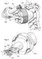
- Fig. 1 shows, in a perspective view, an embodiment of an indexible turning tool according to the present invention;
- Fig. 2 shows a detail of the cutting head of the tool according to Fig. 1; wherein the cutting head is provided with three exchangeable (replaceably) inserts;
- Fig. 3 shows a detail of an alternative cutting head of a tool according to the present invention;
- Fig. 4 shows a detail of an alternatively cutting head;
- Fig. 5 shows, in a perspective view, an alternative embodiment of a tool according to the present invention, wherein the tool is in engagement with a workpiece and the forces acting on the tool;
- Fig. 6 shows in detail the cutting head of the tool according to Fig. 5;
- Fig. 7 shows how the tool according to Fig. 5 is used in threading;
- Fig. 8 shows in a perspective view an alternative tool according to the present invention, where two replaceable inserts are oriented according to principles of the present invention; and
- Fig. 9 shows, in a perspective view, the tool according to Fig. 8 during machining of a rotary work piece.
-
- The present invention relates to a turning tool, wherein a "turning tool" of the present invention shall understood to be a non-rotary tool which for example can perform cutoff operations, grooving, turn milling, etc. The turning tool is indexible about a longitudinal center axis to enable one of a plurality of exchangeable cutting inserts to be placed in an operative cutting position. Additionally, each of the inserts is itself indexible.
- The tool according to the present invention as shown in Fig. 1 comprises a tool body that includes a
holder 1 and asecuring portion 9. Theholder 1 is provided at its free end with a number of insert pockets for receiving replaceable,indexible inserts - All inserts 3-7 are oriented such that their respective main planes P extend laterally in relation to the longitudinal center axis CL of the holder. The "main plane" shall be understood as a plane which coincides with the bottom surface of the insert.
- As is shown in Fig. 1 the
holder 1 is non-centrally (i.e., eccentrically) located on the securingportion 9 of the tool body, which is intended to be tightened firmly in a tool machine. The reason why the eccentric placement of theholder 1 is possible is that the tool according to the present invention is a turning tool and thus does not rotate during operation. However, it is possible to index the tool, i.e. rotate thesecuring portion 9 about an indexing axis in order to feed a new insert to an operative cutting location. That is, the indexing of the tool can take place by rotating theholder 1 about its longitudinal center axis CL which would thus define an indexing axis. Alternatively, or additionally, indexing could take place by rotating the securingportion 9 about its longitudinal center axis CL' which would thus define an indexing axis. - In Fig. 2 the
inserts insert 3 has been inclined such that its main plane P forms an acute angle α with a perpendicular reference plane oriented perpendicularly to the holder's center axis CL, and wherein the angle lies in a tangential reference plane i.e., a plane oriented generally tangentially relative to a radius of the holder. Such an inclination could be achieved, for example, by rotating theinsert 3 of Fig. 1 about an axis A defined by a radius of theholder 1 that passes through the insert's center axis E (see Fig. 2 for the axis E). From Fig. 2 it will be appreciated that a line L1 extending parallel to the main plane P from an axially forwardmost corner C1 of the insert's front cutting face and through the insert's center axis E forms the angle α with a reference line R1 that lies in the perpendicular reference plane and also passes through both the insert's center axis E and the axially forwardmost corner of the insert's front cutting face. The angle α has suitably a value in the range -45° ≤ β ≤ +45° wherein the angle is measured from the reference line R1, and where the angle α is positive above the reference line R1 and negative under the reference line R1. - In Fig. 3 is shown how
corresponding insert 103 on analternative holder 101 has been inclined at an angle β such that the main plane P forms an acute angle β with a perpendicular reference plane, i.e., a plane oriented perpendicularly to the holder's center axis CL, wherein the angle ß lies in an axial reference plane i.e., a plane that contains the holder's center axis CL. The angle β could be formed, for example, by rotating theinsert 3 of Fig. 1 about an axis F which is: (i) oriented tangent to a radius of theholder 1 and (ii) extends through the insert's center axis E. It will be appreciated that a line L2 extending parallel to the main plane of theinsert 103 from an axially rearmost comer of a front cutting face of the insert and through the insert's center axis E forms the angle β with a reference line R2 which lies in the perpendicular reference plane and which also passes through both the insert's center axis E and the axially rearwardmost comer of the insert's front cutting face. The axially rearwardmost comer of the insert's front cutting face lies adjacent the holder's center axis CL. The angle β has suitably a value in the range -45° ≤ β ≤ +45°, wherein the angle is measured from the reference line R2, and where the angle β is positive above the reference line R2 and negative under the reference line R2. - It will also be appreciated that within the scope of the invention, an insert could be inclined by both of the angles α and β.
- A important feature of the present invention is that the main plane of each of the
inserts 3; 103, 5, 7 has a dimension extending laterally in relation to the axial direction CL of theholder 1; 101, wherein according to the present invention also theinserts 3; 103 are regarded as extending laterally across the axial direction CL despite the fact that they are inclined at a certain angle. Generally, this expression "laterally" is given such an interpretation that not only is the insert located in a plane perpendicularly towards the axial direction CL is included but also the insert is inclined within the indicated angular range. - With the embodiment shown in Fig. 4,
insert 203 on analternative holder 201 has been displaced a certain distance δ in the axial direction CL relative to theremaining inserts inserts inserts - In Fig. 5 shows how an embodiment of a tool according to the present invention is used. The
holder 301 is now centrally (coaxially) oriented in relation to thesecuring portion 309. Fig. 5 shows schematically how one of threeinserts copying insert 305, machines a work piece A3. - Even more detail is shown in Fig. 6 of the inserts of the tool according to Fig. 5, wherein these inserts represent a typical set up of inserts. From Fig. 6 it appears how the
holder 301 is equipped with a turninginsert 303 for heavy duty machining, a copyinginsert 305 and athreading insert 307. Theseinserts - Shown in Fig. 5 is how different forces affect the copying
insert 305, wherein FT designates a tangential force; FA designates an axial force; and FR designates a radial force. The absolute biggest force that influences the insert is the tangential force FT, which in the embodiment according to Fig. 5 has a direction along the longitudinal direction of theholder 301. This means that the tangential force FT is absorbed by theholder 301 without causing a pronounced deflection of theholder 301. The force situation as shown in Fig. 5 entails also less tendency to vibrations than in conventional turning tools. - In Fig. 7 is shown how the tool according to the present invention is used in order to make use of the
threading insert 307 to produce a thread on the rotary work piece A3. - In Fig. 8 is shown an alternative embodiment of a tool according to the present invention. As is shown in Fig. 8 two replaceable
indexible inserts holder 401 according to the principles of the present invention, i.e., the main plane of theinserts third insert 407 of the tool according to Fig. 8 has a conventional orientation on theholder 401. In the embodiment shown in Fig. 8 theinsert 403 is a turning insert while theinsert 405 constitutes a copying insert. Theinserts insert 403 performs heavy duty machining while the copyinginsert 405 performs a finish machining. - Fig. 9 shows examples of how the tool according to Fig. 8 is used when machining a rotary work piece A4. As is shown in Fig. 9 the conventional orientation of the
insert 407 causes this insert for example to become useful for internal turning. - The turning tool according to the present invention thus carries a number of exchangeable inserts, preferably of different types, which entails that this turning tool by indexing thereof can be adjusted simply and quickly between different kinds of turning operations.
- In the above described embodiments, the tool according to the present invention is equipped with inserts of three different types, which makes the tool useful in three different kinds of machining operations. However, one can within the limits of the invention also provide tools equipped with interchangeable inserts of only one or two types that are present in different quantities.
- Generally, in all of the described embodiments of the tool according to the present invention as described the inserts are secured into their insert pockets by central screws. As this is outstanding conventional technique these screws have not been described in further detail. Within the limits of the present invention the interchangeable inserts might be secured in their insert pockets by alternative clamping means, wherein, in a not limiting sence, one example could include the use of a top clamp portion.
Claims (14)
- An indexible turning tool comprising a tool body including a securing portion and a holder projecting from the securing portion, the holder provided with pockets receiving respective replaceable cutting inserts, the pockets arranged wherein indexing of the tool body about an indexing axis brings one of the inserts into an operative cutting position, wherein one of the inserts has a main plane oriented laterally relative to a longitudinal center axis of the holder.
- The indexible turning tool according to claim 1 wherein the main plane of the at least one insert forms an acute angle α with a perpendicular reference plane oriented perpendicularly to the holder's center axis, wherein the angle α lies in a plane oriented generally tangentially relative to a radius of the holder.
- The indexible turning tool according to claim 2 wherein the acute angle is in the range -45° ≤ α ≤ +45°.
- The indexible turning tool according to claim 1 wherein the at least one insert forms an acute angle β with a perpendicular reference plane oriented perpendicularly to the holder's center axis, wherein the acute angle lies in a plane containing the holder's center axis.
- The indexible turning tool according to claim 4 wherein the acute angle β is in the range -45° ≤ α ≤ +45°.
- The indexible tool according to claim 1 wherein a plurality of the inserts have their respective main planes oriented laterally of the holder's center axis, and the one insert is offset from these plurality of inserts along the holder's center axis.
- The indexible turning tool according to claim 6 wherein the one insert is offset from the plurality of inserts in a direction toward the securing portion.
- The indexible turning tool according to claim 1 wherein at least an additional one of the inserts has its main plane oriented laterally relative to the holder's center axis, wherein the inserts whose main planes are oriented laterally of the holder's center axis are configured differently from one another.
- The indexible turning tool according to claim 1 wherein a main plane of at least one of the inserts is oriented substantially parallel to the holder's center axis.
- The indexible turning tool according to claim 1 wherein the inserts consist of three inserts spaced circumferentially about the holder's center axis.
- The indexible turning tool according to claim 1 wherein respective radial spacings of the inserts from the holder's center axis are different from one another.
- The indexible turning tool according to claim 1 wherein the inserts are indexible relative to the holder and relative to each other.
- The indexible turning tool according to claim 1 wherein the holder's center axis is arranged eccentrically with respect to a center longitudinal axis of the securing portion.
- The indexible turning tool according to claim 1 wherein the holder's center axis is coincides with a longitudinal center axis of the securing portion.
Applications Claiming Priority (2)
| Application Number | Priority Date | Filing Date | Title |
|---|---|---|---|
| SE0203199 | 2002-10-31 | ||
| SE0203199A SE526480C2 (en) | 2002-10-31 | 2002-10-31 | Chip separating tool |
Publications (2)
| Publication Number | Publication Date |
|---|---|
| EP1415742A1 true EP1415742A1 (en) | 2004-05-06 |
| EP1415742B1 EP1415742B1 (en) | 2008-10-08 |
Family
ID=20289409
Family Applications (1)
| Application Number | Title | Priority Date | Filing Date |
|---|---|---|---|
| EP03445123A Expired - Lifetime EP1415742B1 (en) | 2002-10-31 | 2003-10-28 | Indexible turning tool for chipforming machining |
Country Status (7)
| Country | Link |
|---|---|
| US (2) | US7021182B2 (en) |
| EP (1) | EP1415742B1 (en) |
| JP (1) | JP4494755B2 (en) |
| KR (2) | KR20040038851A (en) |
| AT (1) | ATE410254T1 (en) |
| DE (1) | DE60323919D1 (en) |
| SE (1) | SE526480C2 (en) |
Cited By (7)
| Publication number | Priority date | Publication date | Assignee | Title |
|---|---|---|---|---|
| US7607867B2 (en) | 2006-12-15 | 2009-10-27 | Sandvik Intellectual Property Ab | Tooling insert with mating surface |
| US7845256B2 (en) | 2004-01-30 | 2010-12-07 | Sandvik Intellectual Property Ab | Cutting tool and a tool part with connecting surfaces with grooves and a method for manufacturing of the tool part |
| EP3501701A1 (en) * | 2017-12-22 | 2019-06-26 | Ceratizit Austria Gesellschaft m.b.H. | Tool system and method for turning |
| EP3536428A1 (en) * | 2018-03-08 | 2019-09-11 | AB Sandvik Coromant | A turning method for a cnc-lathe and a turning tool |
| EP3536425A1 (en) * | 2018-03-08 | 2019-09-11 | AB Sandvik Coromant | Turning method for a cnc-lathe |
| US10661361B2 (en) | 2017-04-10 | 2020-05-26 | Fanuc Corporation | Milling/cutting tool and processing apparatus |
| IT202200026868A1 (en) * | 2022-12-27 | 2024-06-27 | Tecno Lain S R L | THREADING TOOL INCLUDING REMOVABLE CUTTING INSERTS |
Families Citing this family (16)
| Publication number | Priority date | Publication date | Assignee | Title |
|---|---|---|---|---|
| DE10228503A1 (en) * | 2002-06-21 | 2004-01-15 | MAPAL Fabrik für Präzisionswerkzeuge Dr. Kress KG | Tool for machining valve seats |
| US7287937B2 (en) * | 2004-08-09 | 2007-10-30 | Hsin-Tien Chang | Multi-function milling cutter |
| US20070000360A1 (en) * | 2005-07-01 | 2007-01-04 | Colarelli Nicholas J Iii | Tool for an automobile brake lathe |
| US20080089750A1 (en) * | 2006-10-16 | 2008-04-17 | Hsin-Tien Chang | Universal Turning and Milling Tool |
| US20080228313A1 (en) * | 2007-03-05 | 2008-09-18 | Mori Seiki Usa, Inc. | Device and Method for Turning In Virtual Planes |
| JP2011518048A (en) * | 2008-03-17 | 2011-06-23 | エイ. サプロック,クリストファー | Smart machining system and smart tool holder used therefor |
| EP3112060A4 (en) * | 2014-02-27 | 2017-12-13 | Murata Machinery, Ltd. | Machine tool |
| EP3162478B1 (en) * | 2014-06-27 | 2023-03-29 | Murata Machinery, Ltd. | Machine tool and machining method |
| US10189092B2 (en) * | 2015-02-10 | 2019-01-29 | Doosan Machine Tools Co., Ltd. | Machine tool |
| WO2016170845A1 (en) * | 2015-04-20 | 2016-10-27 | 村田機械株式会社 | Machine tool and cutting method |
| DE102016101145B4 (en) * | 2016-01-22 | 2019-06-27 | Hartmetall-Werkzeugfabrik Paul Horn Gmbh | milling tool |
| EP3357612B1 (en) * | 2017-02-03 | 2022-11-02 | Sandvik Intellectual Property AB | Method of machining a groove |
| EP3536427B1 (en) * | 2018-03-08 | 2022-08-17 | AB Sandvik Coromant | Turning tool and turning method for cnc-machines |
| EP3838455A1 (en) * | 2019-12-17 | 2021-06-23 | Ceratizit Austria Gesellschaft m.b.H. | Tool system |
| JP2022162321A (en) * | 2021-04-12 | 2022-10-24 | 株式会社不二越 | Turning tools for multitasking machines |
| JP7004107B1 (en) | 2021-07-02 | 2022-01-21 | 株式会社タンガロイ | Holders and cutting tools |
Citations (3)
| Publication number | Priority date | Publication date | Assignee | Title |
|---|---|---|---|---|
| US4475853A (en) * | 1982-12-30 | 1984-10-09 | Deere & Company | Rotary tool and guide |
| EP1070563A1 (en) * | 1998-03-12 | 2001-01-24 | NT Engineering Kabushiki Kaisha | Tool positioning structure and working machine |
| EP1186367A1 (en) * | 2000-09-05 | 2002-03-13 | Yamazaki Mazak Kabushiki Kaisha | Complex tool |
Family Cites Families (9)
| Publication number | Priority date | Publication date | Assignee | Title |
|---|---|---|---|---|
| US3540323A (en) * | 1968-06-17 | 1970-11-17 | Caterpillar Tractor Co | Drill having indexable carbide inserts |
| US4194862A (en) * | 1978-09-05 | 1980-03-25 | The Valeron Corporation | Indexable insert drill |
| JPS5965978A (en) * | 1982-09-21 | 1984-04-14 | ゼロツクス・コ−ポレ−シヨン | Optical disc cartridge |
| DE3239178A1 (en) * | 1982-10-22 | 1984-04-26 | Natec Reich, Summer GmbH & Co KG, 8999 Heimenkirch | MACHINE FOR CUTTING CUT BAR |
| AT5009U1 (en) * | 2001-05-18 | 2002-02-25 | Plansee Tizit Ag | METHOD FOR TURNING |
| US6652200B2 (en) * | 2001-11-01 | 2003-11-25 | Rolf H. Kraemer | Tool holder with coolant system |
| SE520680C2 (en) * | 2001-12-10 | 2003-08-12 | Sandvik Ab | Tool holder with adapter with divergent side surfaces |
| SE523755C2 (en) * | 2002-02-22 | 2004-05-11 | Seco Tools Ab | Cutting tools and holders |
| SE526037C2 (en) * | 2003-02-06 | 2005-06-21 | Sandvik Ab | Chip separator machining tool for rotary machining and turning |
-
2002
- 2002-10-31 SE SE0203199A patent/SE526480C2/en unknown
-
2003
- 2003-10-27 US US10/692,864 patent/US7021182B2/en not_active Expired - Fee Related
- 2003-10-28 AT AT03445123T patent/ATE410254T1/en not_active IP Right Cessation
- 2003-10-28 EP EP03445123A patent/EP1415742B1/en not_active Expired - Lifetime
- 2003-10-28 DE DE60323919T patent/DE60323919D1/en not_active Expired - Lifetime
- 2003-10-30 KR KR1020030076378A patent/KR20040038851A/en not_active Ceased
- 2003-10-31 JP JP2003372022A patent/JP4494755B2/en not_active Expired - Fee Related
-
2005
- 2005-11-23 US US11/286,901 patent/US7219584B2/en not_active Expired - Fee Related
-
2007
- 2007-12-06 KR KR1020070125890A patent/KR100851796B1/en not_active Expired - Fee Related
Patent Citations (3)
| Publication number | Priority date | Publication date | Assignee | Title |
|---|---|---|---|---|
| US4475853A (en) * | 1982-12-30 | 1984-10-09 | Deere & Company | Rotary tool and guide |
| EP1070563A1 (en) * | 1998-03-12 | 2001-01-24 | NT Engineering Kabushiki Kaisha | Tool positioning structure and working machine |
| EP1186367A1 (en) * | 2000-09-05 | 2002-03-13 | Yamazaki Mazak Kabushiki Kaisha | Complex tool |
Cited By (16)
| Publication number | Priority date | Publication date | Assignee | Title |
|---|---|---|---|---|
| US7845256B2 (en) | 2004-01-30 | 2010-12-07 | Sandvik Intellectual Property Ab | Cutting tool and a tool part with connecting surfaces with grooves and a method for manufacturing of the tool part |
| US7607867B2 (en) | 2006-12-15 | 2009-10-27 | Sandvik Intellectual Property Ab | Tooling insert with mating surface |
| US10661361B2 (en) | 2017-04-10 | 2020-05-26 | Fanuc Corporation | Milling/cutting tool and processing apparatus |
| DE102018204964B4 (en) | 2017-04-10 | 2024-02-22 | Fanuc Corporation | Milling/cutting tool and processing device |
| US11806791B2 (en) | 2017-12-22 | 2023-11-07 | Ceratizit Austria Gesellschaft M.B.H | Method for turning a workpiece with a tool system |
| US11396051B2 (en) | 2017-12-22 | 2022-07-26 | Ceratizit Austria Gmbh | Tool system and method for turning |
| WO2019120824A1 (en) * | 2017-12-22 | 2019-06-27 | Ceratizit Austria Gesellschaft M.B.H. | Tool system and method for turning |
| EP3501701A1 (en) * | 2017-12-22 | 2019-06-26 | Ceratizit Austria Gesellschaft m.b.H. | Tool system and method for turning |
| EP3536425A1 (en) * | 2018-03-08 | 2019-09-11 | AB Sandvik Coromant | Turning method for a cnc-lathe |
| WO2019170326A1 (en) * | 2018-03-08 | 2019-09-12 | Ab Sandvik Coromant | A turning method for a cnc-lathe and a turning tool |
| WO2019170325A1 (en) * | 2018-03-08 | 2019-09-12 | Ab Sandvik Coromant | Turning method for a cnc-lathe |
| EP3536428A1 (en) * | 2018-03-08 | 2019-09-11 | AB Sandvik Coromant | A turning method for a cnc-lathe and a turning tool |
| EP3536428B1 (en) | 2018-03-08 | 2022-08-10 | AB Sandvik Coromant | A turning method for a cnc-lathe and a turning tool |
| EP3536425B1 (en) | 2018-03-08 | 2023-08-16 | AB Sandvik Coromant | Turning method for a cnc-lathe |
| US12172218B2 (en) | 2018-03-08 | 2024-12-24 | Ab Sandvik Coromant | Turning method for a CNC-lathe and a turning tool |
| IT202200026868A1 (en) * | 2022-12-27 | 2024-06-27 | Tecno Lain S R L | THREADING TOOL INCLUDING REMOVABLE CUTTING INSERTS |
Also Published As
| Publication number | Publication date |
|---|---|
| DE60323919D1 (en) | 2008-11-20 |
| US7021182B2 (en) | 2006-04-04 |
| JP2004148498A (en) | 2004-05-27 |
| ATE410254T1 (en) | 2008-10-15 |
| KR100851796B1 (en) | 2008-08-13 |
| US7219584B2 (en) | 2007-05-22 |
| SE526480C2 (en) | 2005-09-20 |
| KR20040038851A (en) | 2004-05-08 |
| SE0203199L (en) | 2004-05-01 |
| EP1415742B1 (en) | 2008-10-08 |
| JP4494755B2 (en) | 2010-06-30 |
| US20040131433A1 (en) | 2004-07-08 |
| SE0203199D0 (en) | 2002-10-31 |
| US20060075858A1 (en) | 2006-04-13 |
| KR20080002722A (en) | 2008-01-04 |
Similar Documents
| Publication | Publication Date | Title |
|---|---|---|
| US7021182B2 (en) | Indexible turning tool for chipforming machining | |
| EP1635977B1 (en) | A milling tool with co-operating projections and recessess between the cutting insert and the holder | |
| EP2101947B1 (en) | Cutting insert and cutting tool | |
| US8360694B2 (en) | Rotatable multi-operation tool for chip removing machining, and a basic body therefor | |
| US6213691B1 (en) | Circular drill cutter with indexable inserts and pertaining tip seats | |
| WO2003099495A1 (en) | Drilling tool set, drilling tool and indexable drill bit therefore | |
| EP1635976B1 (en) | Indexable insert with corners with different radii | |
| US5779400A (en) | Small-shank tool for automatic lathes | |
| US7534075B2 (en) | Knife plate and tool for machining bore surfaces | |
| CN1747805B (en) | Tools for different types of chip removal | |
| US20240198437A1 (en) | Metal cutting milling tool | |
| US7409896B2 (en) | Tool for chip removing maching | |
| EP0502834B1 (en) | Cutting tool for a peeling operation | |
| AU2002311587A1 (en) | Cutting tool with edge-on mounted inserts | |
| JP2586465B2 (en) | Slow-away cutter | |
| JPH02237702A (en) | Throw away tip |
Legal Events
| Date | Code | Title | Description |
|---|---|---|---|
| PUAI | Public reference made under article 153(3) epc to a published international application that has entered the european phase |
Free format text: ORIGINAL CODE: 0009012 |
|
| AK | Designated contracting states |
Kind code of ref document: A1 Designated state(s): AT BE BG CH CY CZ DE DK EE ES FI FR GB GR HU IE IT LI LU MC NL PT RO SE SI SK TR |
|
| AX | Request for extension of the european patent |
Extension state: AL LT LV MK |
|
| 17P | Request for examination filed |
Effective date: 20041022 |
|
| AKX | Designation fees paid |
Designated state(s): AT BE BG CH CY CZ DE DK EE ES FI FR GB GR HU IE IT LI LU MC NL PT RO SE SI SK TR |
|
| RAP1 | Party data changed (applicant data changed or rights of an application transferred) |
Owner name: SANDVIK INTELLECTUAL PROPERTY HB |
|
| RAP1 | Party data changed (applicant data changed or rights of an application transferred) |
Owner name: SANDVIK INTELLECTUAL PROPERTY AB |
|
| 17Q | First examination report despatched |
Effective date: 20070613 |
|
| GRAP | Despatch of communication of intention to grant a patent |
Free format text: ORIGINAL CODE: EPIDOSNIGR1 |
|
| GRAS | Grant fee paid |
Free format text: ORIGINAL CODE: EPIDOSNIGR3 |
|
| GRAA | (expected) grant |
Free format text: ORIGINAL CODE: 0009210 |
|
| AK | Designated contracting states |
Kind code of ref document: B1 Designated state(s): AT BE BG CH CY CZ DE DK EE ES FI FR GB GR HU IE IT LI LU MC NL PT RO SE SI SK TR |
|
| REG | Reference to a national code |
Ref country code: GB Ref legal event code: FG4D |
|
| REG | Reference to a national code |
Ref country code: CH Ref legal event code: EP |
|
| REG | Reference to a national code |
Ref country code: IE Ref legal event code: FG4D |
|
| REF | Corresponds to: |
Ref document number: 60323919 Country of ref document: DE Date of ref document: 20081120 Kind code of ref document: P |
|
| PG25 | Lapsed in a contracting state [announced via postgrant information from national office to epo] |
Ref country code: SI Free format text: LAPSE BECAUSE OF FAILURE TO SUBMIT A TRANSLATION OF THE DESCRIPTION OR TO PAY THE FEE WITHIN THE PRESCRIBED TIME-LIMIT Effective date: 20081008 |
|
| NLV1 | Nl: lapsed or annulled due to failure to fulfill the requirements of art. 29p and 29m of the patents act | ||
| PG25 | Lapsed in a contracting state [announced via postgrant information from national office to epo] |
Ref country code: AT Free format text: LAPSE BECAUSE OF FAILURE TO SUBMIT A TRANSLATION OF THE DESCRIPTION OR TO PAY THE FEE WITHIN THE PRESCRIBED TIME-LIMIT Effective date: 20081008 Ref country code: BG Free format text: LAPSE BECAUSE OF FAILURE TO SUBMIT A TRANSLATION OF THE DESCRIPTION OR TO PAY THE FEE WITHIN THE PRESCRIBED TIME-LIMIT Effective date: 20090108 Ref country code: ES Free format text: LAPSE BECAUSE OF FAILURE TO SUBMIT A TRANSLATION OF THE DESCRIPTION OR TO PAY THE FEE WITHIN THE PRESCRIBED TIME-LIMIT Effective date: 20090119 |
|
| PG25 | Lapsed in a contracting state [announced via postgrant information from national office to epo] |
Ref country code: PT Free format text: LAPSE BECAUSE OF FAILURE TO SUBMIT A TRANSLATION OF THE DESCRIPTION OR TO PAY THE FEE WITHIN THE PRESCRIBED TIME-LIMIT Effective date: 20090218 Ref country code: MC Free format text: LAPSE BECAUSE OF NON-PAYMENT OF DUE FEES Effective date: 20081031 Ref country code: FI Free format text: LAPSE BECAUSE OF FAILURE TO SUBMIT A TRANSLATION OF THE DESCRIPTION OR TO PAY THE FEE WITHIN THE PRESCRIBED TIME-LIMIT Effective date: 20081008 Ref country code: NL Free format text: LAPSE BECAUSE OF FAILURE TO SUBMIT A TRANSLATION OF THE DESCRIPTION OR TO PAY THE FEE WITHIN THE PRESCRIBED TIME-LIMIT Effective date: 20081008 |
|
| REG | Reference to a national code |
Ref country code: CH Ref legal event code: PL |
|
| PG25 | Lapsed in a contracting state [announced via postgrant information from national office to epo] |
Ref country code: BE Free format text: LAPSE BECAUSE OF FAILURE TO SUBMIT A TRANSLATION OF THE DESCRIPTION OR TO PAY THE FEE WITHIN THE PRESCRIBED TIME-LIMIT Effective date: 20081008 Ref country code: EE Free format text: LAPSE BECAUSE OF FAILURE TO SUBMIT A TRANSLATION OF THE DESCRIPTION OR TO PAY THE FEE WITHIN THE PRESCRIBED TIME-LIMIT Effective date: 20081008 Ref country code: DK Free format text: LAPSE BECAUSE OF FAILURE TO SUBMIT A TRANSLATION OF THE DESCRIPTION OR TO PAY THE FEE WITHIN THE PRESCRIBED TIME-LIMIT Effective date: 20081008 Ref country code: RO Free format text: LAPSE BECAUSE OF FAILURE TO SUBMIT A TRANSLATION OF THE DESCRIPTION OR TO PAY THE FEE WITHIN THE PRESCRIBED TIME-LIMIT Effective date: 20081008 |
|
| PLBE | No opposition filed within time limit |
Free format text: ORIGINAL CODE: 0009261 |
|
| STAA | Information on the status of an ep patent application or granted ep patent |
Free format text: STATUS: NO OPPOSITION FILED WITHIN TIME LIMIT |
|
| PG25 | Lapsed in a contracting state [announced via postgrant information from national office to epo] |
Ref country code: SE Free format text: LAPSE BECAUSE OF FAILURE TO SUBMIT A TRANSLATION OF THE DESCRIPTION OR TO PAY THE FEE WITHIN THE PRESCRIBED TIME-LIMIT Effective date: 20090108 Ref country code: CZ Free format text: LAPSE BECAUSE OF FAILURE TO SUBMIT A TRANSLATION OF THE DESCRIPTION OR TO PAY THE FEE WITHIN THE PRESCRIBED TIME-LIMIT Effective date: 20081008 Ref country code: IT Free format text: LAPSE BECAUSE OF FAILURE TO SUBMIT A TRANSLATION OF THE DESCRIPTION OR TO PAY THE FEE WITHIN THE PRESCRIBED TIME-LIMIT Effective date: 20081008 |
|
| 26N | No opposition filed |
Effective date: 20090709 |
|
| PG25 | Lapsed in a contracting state [announced via postgrant information from national office to epo] |
Ref country code: SK Free format text: LAPSE BECAUSE OF FAILURE TO SUBMIT A TRANSLATION OF THE DESCRIPTION OR TO PAY THE FEE WITHIN THE PRESCRIBED TIME-LIMIT Effective date: 20081008 |
|
| PG25 | Lapsed in a contracting state [announced via postgrant information from national office to epo] |
Ref country code: CH Free format text: LAPSE BECAUSE OF NON-PAYMENT OF DUE FEES Effective date: 20081031 Ref country code: LI Free format text: LAPSE BECAUSE OF NON-PAYMENT OF DUE FEES Effective date: 20081031 Ref country code: IE Free format text: LAPSE BECAUSE OF NON-PAYMENT OF DUE FEES Effective date: 20081028 |
|
| PG25 | Lapsed in a contracting state [announced via postgrant information from national office to epo] |
Ref country code: LU Free format text: LAPSE BECAUSE OF NON-PAYMENT OF DUE FEES Effective date: 20081028 Ref country code: CY Free format text: LAPSE BECAUSE OF FAILURE TO SUBMIT A TRANSLATION OF THE DESCRIPTION OR TO PAY THE FEE WITHIN THE PRESCRIBED TIME-LIMIT Effective date: 20081008 Ref country code: HU Free format text: LAPSE BECAUSE OF FAILURE TO SUBMIT A TRANSLATION OF THE DESCRIPTION OR TO PAY THE FEE WITHIN THE PRESCRIBED TIME-LIMIT Effective date: 20090409 |
|
| PG25 | Lapsed in a contracting state [announced via postgrant information from national office to epo] |
Ref country code: TR Free format text: LAPSE BECAUSE OF FAILURE TO SUBMIT A TRANSLATION OF THE DESCRIPTION OR TO PAY THE FEE WITHIN THE PRESCRIBED TIME-LIMIT Effective date: 20081008 |
|
| PG25 | Lapsed in a contracting state [announced via postgrant information from national office to epo] |
Ref country code: GR Free format text: LAPSE BECAUSE OF FAILURE TO SUBMIT A TRANSLATION OF THE DESCRIPTION OR TO PAY THE FEE WITHIN THE PRESCRIBED TIME-LIMIT Effective date: 20090109 |
|
| REG | Reference to a national code |
Ref country code: FR Ref legal event code: PLFP Year of fee payment: 14 |
|
| PGFP | Annual fee paid to national office [announced via postgrant information from national office to epo] |
Ref country code: FR Payment date: 20160919 Year of fee payment: 14 |
|
| PGFP | Annual fee paid to national office [announced via postgrant information from national office to epo] |
Ref country code: GB Payment date: 20161026 Year of fee payment: 14 Ref country code: DE Payment date: 20161025 Year of fee payment: 14 |
|
| REG | Reference to a national code |
Ref country code: DE Ref legal event code: R119 Ref document number: 60323919 Country of ref document: DE |
|
| GBPC | Gb: european patent ceased through non-payment of renewal fee |
Effective date: 20171028 |
|
| REG | Reference to a national code |
Ref country code: FR Ref legal event code: ST Effective date: 20180629 |
|
| PG25 | Lapsed in a contracting state [announced via postgrant information from national office to epo] |
Ref country code: DE Free format text: LAPSE BECAUSE OF NON-PAYMENT OF DUE FEES Effective date: 20180501 Ref country code: GB Free format text: LAPSE BECAUSE OF NON-PAYMENT OF DUE FEES Effective date: 20171028 |
|
| PG25 | Lapsed in a contracting state [announced via postgrant information from national office to epo] |
Ref country code: FR Free format text: LAPSE BECAUSE OF NON-PAYMENT OF DUE FEES Effective date: 20171031 |