EP1415388B1 - Odd harmonics reduction of phase angle controlled loads - Google Patents
Odd harmonics reduction of phase angle controlled loads Download PDFInfo
- Publication number
- EP1415388B1 EP1415388B1 EP02736951A EP02736951A EP1415388B1 EP 1415388 B1 EP1415388 B1 EP 1415388B1 EP 02736951 A EP02736951 A EP 02736951A EP 02736951 A EP02736951 A EP 02736951A EP 1415388 B1 EP1415388 B1 EP 1415388B1
- Authority
- EP
- European Patent Office
- Prior art keywords
- phase angle
- phase
- predetermined range
- alternating current
- load
- Prior art date
- Legal status (The legal status is an assumption and is not a legal conclusion. Google has not performed a legal analysis and makes no representation as to the accuracy of the status listed.)
- Expired - Lifetime
Links
- 238000012937 correction Methods 0.000 claims description 7
- 238000000034 method Methods 0.000 claims description 7
- 238000012545 processing Methods 0.000 claims description 7
- 238000012986 modification Methods 0.000 claims description 4
- 230000004048 modification Effects 0.000 claims description 4
- 238000001514 detection method Methods 0.000 claims 2
- 230000008878 coupling Effects 0.000 claims 1
- 238000010168 coupling process Methods 0.000 claims 1
- 238000005859 coupling reaction Methods 0.000 claims 1
- 238000010304 firing Methods 0.000 description 19
- 239000004020 conductor Substances 0.000 description 12
- 230000006870 function Effects 0.000 description 12
- 238000012546 transfer Methods 0.000 description 12
- 238000010586 diagram Methods 0.000 description 6
- 229910003460 diamond Inorganic materials 0.000 description 4
- 239000010432 diamond Substances 0.000 description 4
- 230000007935 neutral effect Effects 0.000 description 4
- 238000004364 calculation method Methods 0.000 description 3
- 238000013461 design Methods 0.000 description 1
- 230000000694 effects Effects 0.000 description 1
- 230000005294 ferromagnetic effect Effects 0.000 description 1
- 230000005291 magnetic effect Effects 0.000 description 1
- 230000003287 optical effect Effects 0.000 description 1
- 230000003068 static effect Effects 0.000 description 1
- 238000013519 translation Methods 0.000 description 1
- 238000005406 washing Methods 0.000 description 1
Images



Classifications
-
- H—ELECTRICITY
- H02—GENERATION; CONVERSION OR DISTRIBUTION OF ELECTRIC POWER
- H02M—APPARATUS FOR CONVERSION BETWEEN AC AND AC, BETWEEN AC AND DC, OR BETWEEN DC AND DC, AND FOR USE WITH MAINS OR SIMILAR POWER SUPPLY SYSTEMS; CONVERSION OF DC OR AC INPUT POWER INTO SURGE OUTPUT POWER; CONTROL OR REGULATION THEREOF
- H02M5/00—Conversion of AC power input into AC power output, e.g. for change of voltage, for change of frequency, for change of number of phases
- H02M5/02—Conversion of AC power input into AC power output, e.g. for change of voltage, for change of frequency, for change of number of phases without intermediate conversion into DC
- H02M5/04—Conversion of AC power input into AC power output, e.g. for change of voltage, for change of frequency, for change of number of phases without intermediate conversion into DC by static converters
- H02M5/22—Conversion of AC power input into AC power output, e.g. for change of voltage, for change of frequency, for change of number of phases without intermediate conversion into DC by static converters using discharge tubes with control electrode or semiconductor devices with control electrode
- H02M5/25—Conversion of AC power input into AC power output, e.g. for change of voltage, for change of frequency, for change of number of phases without intermediate conversion into DC by static converters using discharge tubes with control electrode or semiconductor devices with control electrode using devices of a thyratron or thyristor type requiring extinguishing means
- H02M5/257—Conversion of AC power input into AC power output, e.g. for change of voltage, for change of frequency, for change of number of phases without intermediate conversion into DC by static converters using discharge tubes with control electrode or semiconductor devices with control electrode using devices of a thyratron or thyristor type requiring extinguishing means using semiconductor devices only
- H02M5/2573—Conversion of AC power input into AC power output, e.g. for change of voltage, for change of frequency, for change of number of phases without intermediate conversion into DC by static converters using discharge tubes with control electrode or semiconductor devices with control electrode using devices of a thyratron or thyristor type requiring extinguishing means using semiconductor devices only with control circuit
- H02M5/2576—Conversion of AC power input into AC power output, e.g. for change of voltage, for change of frequency, for change of number of phases without intermediate conversion into DC by static converters using discharge tubes with control electrode or semiconductor devices with control electrode using devices of a thyratron or thyristor type requiring extinguishing means using semiconductor devices only with control circuit with digital control
-
- H—ELECTRICITY
- H02—GENERATION; CONVERSION OR DISTRIBUTION OF ELECTRIC POWER
- H02P—CONTROL OR REGULATION OF ELECTRIC MOTORS, ELECTRIC GENERATORS OR DYNAMO-ELECTRIC CONVERTERS; CONTROLLING TRANSFORMERS, REACTORS OR CHOKE COILS
- H02P23/00—Arrangements or methods for the control of AC motors characterised by a control method other than vector control
- H02P23/18—Controlling the angular speed together with angular position or phase
- H02P23/186—Controlling the angular speed together with angular position or phase of one shaft by controlling the prime mover
-
- H—ELECTRICITY
- H02—GENERATION; CONVERSION OR DISTRIBUTION OF ELECTRIC POWER
- H02M—APPARATUS FOR CONVERSION BETWEEN AC AND AC, BETWEEN AC AND DC, OR BETWEEN DC AND DC, AND FOR USE WITH MAINS OR SIMILAR POWER SUPPLY SYSTEMS; CONVERSION OF DC OR AC INPUT POWER INTO SURGE OUTPUT POWER; CONTROL OR REGULATION THEREOF
- H02M1/00—Details of apparatus for conversion
- H02M1/12—Arrangements for reducing harmonics from AC input or output
Definitions
- the present invention relates generally to harmonics reduction, and more specifically to odd harmonics reduction of phase angle controlled loads.
- An apparatus for suppressing higher harmonics in an AC power supply is shown in the japanese patent JP2000308353.
- Phase angle control may be used to control different types of AC loads.
- Phase angle control is a method of controlling the effective average voltage applied to a load by using an electronic switch and varying the conduction angle. Because the current waveform driving the loads are generally not sinusoidal waveforms, harmonic currents are introduced which causes distortion in the voltage waveforms. This distortion can also affect other loads that are coupled to the same power supply.
- Active power correction circuitry used to reduce harmonics is often used in computer switchmode power supplies and some lighting applications.
- One known active power correction circuitry uses a boost power supply with a power MOSFET as the switching device.
- the power MOSFET controls the current flowing to the output. While the power MOSFET is applicable for low-power applications, it becomes prohibitively expensive above 1,000 Watts.
- IGBTs Insulated Gate Bipolar Transistors
- a power supply in that uses inverters for providing the AC current where the transistors the inverters are operated alternately to provide alternate positive and negative half cycles.
- the power supply described in this reference includes a device for reducing amplitude of at least a second harmonic of a fundamental frequency of the current output by the inverter so that a filter connected to the load circuit can have a roll-off frequency close to the design frequency of the load circuit. Therefore, a need exists for an effective phase angle control system that is capable of reducing harmonics while being able to handle higher power loads. This need is met by the subject-matter claimed in independent claims 1, 7 and 10 in accordance with the present invention.
- FIG. 1 illustrates in block diagram form, a harmonics reduction system 10 in accordance with one embodiment of the present invention.
- System 10 includes a processor 14, a speed control unit 12, a triac drive unit 16, a memory 19, a zero crossing unit 18, a triac 22, and a load 20.
- Processor 14 is coupled to speed control unit 12 (via conductor 13), triac drive unit 16 (via conductor 15), zero crossing unit 18 (via conductor 17), and memory 19.
- Processor 14 may be a microprocessor (MPU), microcontroller (MCU), a digital signal processor (DSP), a data processing system, or any other type of processor.
- Memory 19 may be an embedded memory within processor 14, or may include one or more external memory units.
- Memory 19 may be any appropriate type of memory, such as, for example, Flash, EEPROM, EPROM, ROM, RAM, MRAM, etc.
- Triac drive unit 16 is coupled to triac 22 (via conductor 24), where triac 22 receives the neutral input from an alternating current (AC) power supply (not shown) and is coupled to load 20. (Note that in place of triac 22, any thyristor may be used.)
- Load 20 is coupled to zero crossing unit 18, and receives the line input from the AC power supply. Zero crossing unit 18 also receives the line input.
- the neutral and line inputs may correspond to an input power supply applied to load 20, such as, for example, a wall socket or other AC power supply, where the line input is the live input ideally having a sinusoidal waveform.
- load 20 such as, for example, a wall socket or other AC power supply
- the sinusoidal waveform is usually distorted, thus resulting in a non-sinusoidal AC power supply.
- the line input to load 20 may be non-sinusoidal.
- system 10 provides phase angle control and reduces odd harmonics introduced by load 20.
- Load 20 may be any phase controlled load, such as, for example, a universal motor.
- System 10 may therefore be used in many appliances such as vacuum cleaners, light dimmers, heaters, power tools, washing machines, etc. Therefore, system 10 identifies particular phase angles where the harmonic current is above predetermined limits and applies an algorithm to strategically avoid them.
- the predetermined limits on harmonic currents may be those mandated by government regulations, as will be discussed in reference to FIG. 2 below.
- Excessive harmonic currents causes many undesirable effects, such as, for example, introducing distortions into the voltage waveform, which may affect any other loads (e.g. appliances, etc.) coupled to the same power supply. Therefore, system 10 reduces noise, such as harmonic currents, in order to maintain power quality.
- Speed control 12 provides a speed value (i.e. also referred to as a speed control signal) to processor 14, via conductor 13, indicative of a speed setting.
- speed control 12 can be a knob on a motor that allows a user to select the desired motor speed.
- This speed value corresponds to a desired phase angle to be applied to load 20.
- Processor 14 receives this speed value and determines the resulting output phase angle (also referred to as output firing phasing angle) that must be applied to triac 22 via triac drive unit 16 for proper control of load 20.
- output phase angle also referred to as output firing phasing angle
- Triac drive unit 16 therefore applies a triggering current (also referred to as a load control signal) via conductor 24 to triac 22 such that triac 22 latches at the proper firing phase angle (corresponding to the output firing phase angle calculated by processor 14) and couples the neutral input to load 20.
- a triggering current also referred to as a load control signal
- Triac drive unit 16 applies the triggering current such that triac 22 latches at 60 degrees before the next voltage zero crossing of the line input.
- Triac 22 Upon the line input voltage crossing the zero axis, triac 22 is released, thus decoupling the neutral input from load 20.
- Zero crossing unit 18 therefore provides a voltage zero crossing indicator to processor 14 when the line input voltage crosses the zero axis.
- the firing phase angle of triac 22 refers to the number of degrees before the voltage zero crossing of the line input where triac 22 latches.
- Processor 14 uses the speed value received from speed control 12, the zero crossing indicator received from zero crossing unit 18, and instructions stored within memory 19 to reduce harmonic currents, as will be discussed in more detail below.
- FIG. 2 illustrates, in table form, the standards for power quality in Europe as defined in EN61000-3-2. This standard has been adopted by the European Community and is a requirement for CE approval. Therefore, this is one example of limits placed on harmonic currents; however, system 10 may target any predetermined limit on harmonic currents, as appropriate.
- various limits are given on each harmonic current, both even and odd.
- the harmonic current limit i.e. maximum harmonic current
- the harmonic current limit i.e. maximum harmonic current
- the harmonic current limit i.e. maximum harmonic current
- the harmonic current limit for an even harmonic falling between 8 and 40, inclusively, can be calculated by dividing the even harmonic number into 8 and multiplying the result by 0.23.
- the limit (maximum harmonic current) on the third harmonic according to the European standard is 2.3 Amps.
- the third harmonic current for phase angle controlled applications is problematic and can detrimentally distort the power quality. Therefore, system 10 of FIG. 1 can be used to ensure that the third harmonic current does not surpass 2.3 Amps.
- the third harmonic will be used as an example herein, the embodiments described herein may be used to reduce any odd harmonics within system 10, and is not limited to the third harmonic.
- the European standard defines the limit on the third harmonic current as 2.3 Amps; however, any predetermined limit may be set.
- FIG. 3 illustrates, in graph form, the harmonic current corresponding to the third harmonic of an AC power supply.
- Graph 30 graphs one example of a third harmonic current with respect to the firing phase angle of triac 22. Note that in this example, the third harmonic current surpasses its 2.3 Amps limit between the firing phase angles of 60 and 120 degrees (corresponding to points 32 and 34 of FIG. 3, respectively). Therefore, this range is identified as problematic or undesirable where the harmonic current should be reduced.
- FIG. 4 illustrates, in block diagram form, one embodiment of a portion of processor 14.
- Processor 14 includes an A/D (analog to digital) converter 40, scaling unit 42, summers 44 and 48, delay unit 46, transfer function 50, and timer and pulse generator 52.
- A/D converter 40 receives the speed value via conductor 13 from speed control 12 and is coupled to scaling unit 42.
- Scaling unit 42 provides the desired input phase angle (X) to summer 44.
- Summer 48 is coupled to delay unit 46 which is coupled to summer 44.
- Summer 44 provides an error modified desired phase angle (Z) to summer 48 and transfer function 50.
- Transfer function 50 provides the output phase angle (Y) to summer 48 and timer and pulse generator 52.
- Timer and pulse generator 52 also receives the zero crossing indicator from zero crossing unit 18 via conductor 17, and provides an output to triac drive unit 16 via conductor 15.
- A/D converter 40 receives the speed value from speed control 12 and converts it to a digital value.
- speed control 12 is a potentiometer capable of providing a variety of speed values to A/D converter 40.
- Scaling unit 42 receives the digital value from A/D converter 40 and scales it to fall into a predetermined range. For example, in one embodiment, scaling unit 42 scales the digital values received from A/D converter 40 to values between 0 and 180 such that they correspond directly to a desired input phase angle received from speed control unit 12. Therefore, a particular setting on speed control 12 is converted to a desired phase angle (X) that will result in the desired speed of load 20, which in one embodiment, may be a universal motor. (Note that although speed control is being used as an example, other loads may have other variable phase angle controls other than speed, such as brightness control for incandescent lights, temperature control for heaters, etc.)
- Summers 44 and 48, delay unit 46, and transfer function 50 operate to modulate X into an output phase angle (Y) where Y corresponds to the firing phase angle of triac 22.
- Summer 44 receives X and an error (i.e. an error phase) calculated from a previous half cycle (calculated by summer 48 and provided to delay unit 46 such that the error is held from a previous half cycle to a subsequent half cycle) and provides the error modified desired phase angle (Z) to transfer function 50.
- Transfer function 50 is further defined in FIG. 5 which illustrates, in graph form, the translation of the error modified desired phase angle (Z) received from summer 44 to the output Y.
- summers 44 and 48, delay unit 46, and transfer function 50 can be implemented in hardware, software, or in a combination of hardware and software. For example, they can be implemented in software stored in memory 19.
- Timer and pulse generator 52 receives the output firing phase angle (Y) and the zero crossing indicator and provides an indicator via conductor 15 to triac drive unit 16, which applies the triggering current (e.g. a pulse) to triac 22.
- Timer and pulse generator 52 calculates an amount of time to wait from a zero crossing prior to firing triac 22.
- timer and pulse generator 52 waits for the calculated amount of time prior to indicating to triac drive unit 16 (via conductor 15) to generate a pulse such that triac 22 fires at the firing phase angle Y.
- the firing phase angle Y calculated in a current half cycle is not applied until the subsequent half cycle.
- the firing phase angle Y may be applied in the current half cycle or any subsequent half cycle.
- FIG. 8 illustrates, in graph form, one example of the operation of processor 14 corresponding to the third harmonic current of FIG. 3.
- FIG. 8 illustrates an AC power supply voltage waveform (the top waveform) having zero crossings at points 81, 82, 84, and 86.
- the desired input phase angle (X) is calculated to be 61 degrees.
- the error modified desired phase angle (Z) is therefore also 61 degrees (assuming the error from the previous half cycle was zero degrees).
- timer and pulse generator 52 receives Y (which is 1 degree in this example) and calculates the amount of time to wait between a zero crossing and firing triac 22 at 1 degree. Upon finishing this calculation, which is generally finished early in the current half cycle (i.e. shortly after zero crossing 81 or at least prior to zero crossing 82), timer and pulse generator 52 waits for a next zero crossing, zero crossing 82, and then waits the previously calculated amount of time (between point 82 and the start of pulse 88) before causing the triac trigger pulse 88 to fire.
- Y which is 1 degree in this example
- Alternate embodiments may use a time average over more than two half cycles.
- the range can be increased from 60 to 120 degrees to 45 to 135 degrees by modulating over a wider range. For example, if the desired phase angle (X) is between 45 and 90 degrees, 45 degrees is subtracted from the output phase angle. If the desired phase angle (X) is between 90 and 135 degrees, 45 degrees is added to the output phase angle. This results average to the desired angle over three half cycles.
- any of the units described above such as, for example, A/D converter 40, scaling unit 42, and timer and pulse generator 52, may be implemented in hardware, software, or a combination of hardware and software.
- the software may be stored in a memory unit, such as, for example, memory 19 for access by processor 14.
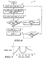
- FIG. 6 illustrates in flow diagram form, a method for reducing odd harmonics according to one embodiment of the present invention that may be used in processor 14.
- Flow 60 of FIG. 6 corresponds to the operation of summer 44 and 48, delay unit 46, transfer function 50 of FIG. 4.
- Flow 60 begins at start 62 and proceeds to block 64 where the desired input phase angle (X) is received (where X may be derived from the speed value received from speed control 12, as described above).
- Flow continues to block 66 where an error from a prior iteration is added to X to create an error modified phase angle (Z). (If this is the first iteration, the error is initialized to zero.) Therefore, block 66 may correspond to summer 44, where the output of summer 44 is Z.
- Y the output phase angle
- the output phase angle (Y) corresponding to the triac firing phase angle
- Z the output phase angle
- decision diamond 70 it is determined whether Y is greater than a predetermined lower limit and less than a predetermined upper limit. These limits correspond to the problem area being avoided. For example, in the case of attempting to reduce the third harmonic current illustrated in FIG. 3, the problem area occurs between the firing phase angles of 60 and 120 degrees. Therefore, in this example, the lower limit may be set to 60 and the upper limit set to 120. If Y is greater than the lower limit and less than the upper limit, flow proceeds to block 72 where the difference between the upper and lower limits (i.e.
- Flow proceeds to block 76 where Y is output for subsequent processing (for example, Y may be provided to timer and pulse generator 52 of FIG. 4).
- Flow proceeds to decision diamond 78 where it is determined whether a next zero crossing has been reached. If not, flow returns to decision diamond 78 until a next zero crossing is reached, at which point flow returns to block 64. Therefore, in block 66, the error from the previous iteration is used.
- flow 60 reduces the third harmonic current of FIG. 3 and allows the time average of output phase angle (Y) over two half cycles to be approximately equivalent to the desired (input) phase angle (X).
- FIG. 7 illustrates, in graph form, the results from applying the flow of FIG. 6. Therefore, flow 60 modulates the desired phase angle (X) such that the output firing phase angle (Y) avoids the problematic range. Therefore, as can be seen in the graph of FIG. 7, which is similar to FIG. 3, the third harmonic current remains below 2.3 Amps. Therefore, it can be appreciated how processor 14 and flow 60 can help reduce odd harmonic currents. Although the above description used the third harmonic current with a 2.3 Amp limit as an example, processor 14 and flow 60 can be modified to take care of any problematic range of firing phase angles for triac 22. For example, the upper and lower limits described in FIG.
- the methods and systems herein may be used for reducing any signal element from a signal within a problematic range, and not just harmonic currents.
- any software taught herein may be embodied on one or more of computer hard disks, floppy disks, 3.5" disks, computer storage tapes, magnetic drums, static random access memory (SRAM) cells, dynamic random access memory (DRAM) cells, electrically erasable (EEPROM, EPROM, flash) cells, nonvolatile cells, ferroelectric or ferromagnetic memory, compact disks (CDs), laser disks, optical disks, and any like computer readable media. Accordingly, the specification and figures are to be regarded in an illustrative rather than a restrictive sense, and all such modifications are intended to be included within the scope of present invention.
Landscapes
- Engineering & Computer Science (AREA)
- Power Engineering (AREA)
- Power Conversion In General (AREA)
- Control Of Electrical Variables (AREA)
Description
Claims (10)
- Apparatus for reducing odd harmonic current introduced into an alternating current supply by a load (20), comprising:zero crossing detection means (18) coupled to the alternating current supply for measuring voltage zero crossings of the alternating current supply; andprocessing means (14) coupled to the zero crossing detection means, the processing means receiving a user control signal (12) for controlling the load, the processing means determining phase angles required at the voltage zero crossings of the alternating current supply to implement the user control signal, and selectively modulating (72) the phase angles when the phase angles are within a predetermined range of an undesired phase angle, the selectively modulating reducing odd harmonics within the alternating current supply.
- The apparatus of claim 1 wherein the load (20) is a motor and the user control signal (12) is a speed control signal for controlling speed of the motor.
- The apparatus of claim 1 wherein the undesired phase angle is approximately ninety degrees to significantly minimize a third harmonic of the alternating current supply.
- The apparatus of claim 1 wherein the predetermined range comprises a range substantially within 30 to 60 degrees wide.
- The apparatus of claim 1 wherein the processing means (14) selectively modulates by subtracting (48) a predetermined correction phase angle from a phase angle within the predetermined range and determining an error phase, the error phase being added (44) to a subsequent phase angle within the predetermined range to average modification of the phase angle.
- The apparatus of claim 1 wherein the processing means (14) further comprises a microcontroller unit (MCU) and the load (20) is a universal motor.
- A method for reducing odd harmonics in an alternating current supply, comprising:receiving a user command (12) to control a load (20);determining a phase angle (64,66,68) at each zero crossing (78) of the alternating current supply required to implement the user command;identifying a predetermined range of phase angles to modulate around;not modifying (70,74) the phase angle if the phase angle is less than the predetermined range of phase angles;modifying (72) the phase angle by performing one of selectively adding and selectively subtracting a predetermined phase from the phase angle if the phase angle is within the predetermined range of phase angles;calculating (48;74) an error in response to modifying the phase angle;adding (44) the error to a subsequent phase angle so that an average phase angle equals required phase angle modification required to implement the user command (12); andnot modifying (70,74) the phase angle if the phase angle is greater than the predetermined range of phase angles.
- The method of claim 7 further comprising implementing the predetermined range of phase angles as substantially between sixty degrees and one hundred twenty degrees.
- The method of claim 7 further comprising:coupling modified or non-modified phase angles to a triac (22) to control switching of the alternating current supply to the load (20).
- A computer readable medium storing software for reducing odd harmonics in an alternating current introduced by a load (20), the computer readable medium comprising:at least one instruction (78,64,66,68) for determining a phase angle at each zero crossing of the alternating current required to implement a user command (15) to control the load (20);at least one instruction (70) for determining if the phase angle at each zero crossing is within or outside a predetermined range of phase angles to modulate around and not changing the phase angle if the phase angle is outside of the predetermined range; andat least one instruction (72) for changing the phase angle by forming a differential between a predetermined phase angle and the phase angle if the phase angle is within the predetermined range, for calculating an error value associated with the phase angle, and for adding (44) the error value to a subsequent phase angle so that an average of two successive phase angles will accurately implement the user command.
Applications Claiming Priority (3)
| Application Number | Priority Date | Filing Date | Title |
|---|---|---|---|
| US09/896,534 US6614197B2 (en) | 2001-06-30 | 2001-06-30 | Odd harmonics reduction of phase angle controlled loads |
| US896534 | 2001-06-30 | ||
| PCT/US2002/015724 WO2003005547A2 (en) | 2001-06-30 | 2002-05-16 | Odd harmonics reduction of phase angle controlled loads |
Publications (2)
| Publication Number | Publication Date |
|---|---|
| EP1415388A2 EP1415388A2 (en) | 2004-05-06 |
| EP1415388B1 true EP1415388B1 (en) | 2005-11-02 |
Family
ID=25406378
Family Applications (1)
| Application Number | Title | Priority Date | Filing Date |
|---|---|---|---|
| EP02736951A Expired - Lifetime EP1415388B1 (en) | 2001-06-30 | 2002-05-16 | Odd harmonics reduction of phase angle controlled loads |
Country Status (5)
| Country | Link |
|---|---|
| US (1) | US6614197B2 (en) |
| EP (1) | EP1415388B1 (en) |
| AU (1) | AU2002309924A1 (en) |
| DE (1) | DE60207087T2 (en) |
| WO (1) | WO2003005547A2 (en) |
Cited By (1)
| Publication number | Priority date | Publication date | Assignee | Title |
|---|---|---|---|---|
| DE102007035954A1 (en) * | 2007-07-30 | 2009-02-05 | Royal Appliance International Gmbh | Electric consumer's e.g. high voltage incandescent lamp, power regulating method for alternating current network, involves selecting phase angles of phase section of half-waves, where finite number of angles is uneven or greater than one |
Families Citing this family (20)
| Publication number | Priority date | Publication date | Assignee | Title |
|---|---|---|---|---|
| US7305986B1 (en) | 1999-07-23 | 2007-12-11 | Mannkind Corporation | Unit dose capsules for use in a dry powder inhaler |
| US7464706B2 (en) | 1999-07-23 | 2008-12-16 | Mannkind Corporation | Unit dose cartridge and dry powder inhaler |
| EP1494732B1 (en) | 2002-03-20 | 2008-01-30 | MannKind Corporation | Inhalation apparatus |
| FR2864373B1 (en) * | 2003-12-18 | 2006-02-17 | Invensys Appliance Controls Sa | ELECTRIC MOTOR CONTROLLER FOR HOUSEHOLD APPLIANCE |
| US20050270814A1 (en) * | 2004-06-02 | 2005-12-08 | In-Hwan Oh | Modified sinusoidal pulse width modulation for full digital power factor correction |
| BRPI0404081A (en) * | 2004-09-22 | 2006-05-02 | Multibras Eletrodomesticos Sa | speed control method of an electric motor |
| AU2006290227B2 (en) | 2005-09-14 | 2012-08-02 | Mannkind Corporation | Method of drug formulation based on increasing the affinity of crystalline microparticle surfaces for active agents |
| US7342372B2 (en) * | 2005-10-05 | 2008-03-11 | Aktiebolaget Electrolux | Method for power control of an electric motor |
| KR20080096809A (en) | 2006-02-22 | 2008-11-03 | 맨카인드 코포레이션 | Method for Improving Pharmaceutical Properties of Microparticles Containing Diketopiperazine and Active Agents |
| US8179064B2 (en) * | 2007-10-16 | 2012-05-15 | Arcfl Technology Limited | Electric motor protection system |
| DE102007060242A1 (en) * | 2007-12-14 | 2009-06-18 | Robert Bosch Gmbh | Method and device for operating an electric drive by means of a phase control |
| SG10201507036TA (en) | 2008-06-13 | 2015-10-29 | Mannkind Corp | A dry powder inhaler and system for drug delivery |
| EP2609954B1 (en) | 2008-06-20 | 2021-12-29 | MannKind Corporation | An interactive apparatus for real-time profiling of inhalation efforts |
| US8240875B2 (en) | 2008-06-25 | 2012-08-14 | Cree, Inc. | Solid state linear array modules for general illumination |
| US8314106B2 (en) | 2008-12-29 | 2012-11-20 | Mannkind Corporation | Substituted diketopiperazine analogs for use as drug delivery agents |
| US8957662B2 (en) | 2009-11-25 | 2015-02-17 | Lutron Electronics Co., Inc. | Load control device for high-efficiency loads |
| HK1200318A1 (en) | 2011-10-24 | 2015-08-07 | 曼金德公司 | Methods and compositions for treating pain |
| US9770991B2 (en) * | 2013-05-31 | 2017-09-26 | GM Global Technology Operations LLC | Systems and methods for initializing a charging system |
| TWI559450B (en) * | 2014-04-18 | 2016-11-21 | 力晶科技股份有限公司 | Memory structure and its operation method |
| CN107465368B (en) * | 2016-05-30 | 2023-09-26 | 德昌电机(深圳)有限公司 | Motor and its driving circuit and driving method |
Family Cites Families (16)
| Publication number | Priority date | Publication date | Assignee | Title |
|---|---|---|---|---|
| US3569841A (en) * | 1968-07-09 | 1971-03-09 | Peter L Richman | Harmonic-rejecting ac-to-dc converter |
| US4912378A (en) * | 1988-07-21 | 1990-03-27 | Emerson Electric Co. | Third harmonic commutation control system and method |
| US5343079A (en) * | 1991-02-25 | 1994-08-30 | Regents Of The University Of Minnesota | Standby power supply with load-current harmonics neutralizer |
| US5548165A (en) * | 1994-07-18 | 1996-08-20 | Regents Of The University Of Minnesota | Hybrid filter for reducing distortion in a power system |
| US5883490A (en) * | 1996-06-14 | 1999-03-16 | Moreira; Julio C. | Electric motor controller and method |
| JP3234909B2 (en) * | 1996-12-13 | 2001-12-04 | シャープ株式会社 | Inverter control device and inverter control method |
| US5955794A (en) | 1997-02-14 | 1999-09-21 | Gerhard Kurz | Method and arrangement for controlling the output of a load connected to an ac line voltage |
| EP0889674B1 (en) * | 1997-07-04 | 2004-02-18 | Sharp Kabushiki Kaisha | Power control unit |
| JPH1132483A (en) * | 1997-07-09 | 1999-02-02 | Mitsubishi Heavy Ind Ltd | Phase control device of thyristor converter |
| JPH11111897A (en) | 1997-10-03 | 1999-04-23 | Hitachi Ltd | Multi-chip type semiconductor device |
| US5994869A (en) * | 1997-12-05 | 1999-11-30 | General Electric Company | Power conversion circuit for a motor |
| JPH11183900A (en) | 1997-12-25 | 1999-07-09 | Hitachi Ltd | Liquid crystal display |
| US6118239A (en) * | 1998-11-23 | 2000-09-12 | Kadah; Andrew S. | Speed control drive circuit for blower motor |
| AUPP944799A0 (en) | 1999-03-25 | 1999-04-22 | H.P.M. Industries Pty Limited | Control circuit |
| JP4289718B2 (en) * | 1999-04-20 | 2009-07-01 | 三洋電機株式会社 | Power supply |
| GB2350733B (en) | 1999-06-03 | 2003-02-12 | Cheltenham Induction Heating L | Power supply |
-
2001
- 2001-06-30 US US09/896,534 patent/US6614197B2/en not_active Expired - Fee Related
-
2002
- 2002-05-16 WO PCT/US2002/015724 patent/WO2003005547A2/en not_active Ceased
- 2002-05-16 DE DE60207087T patent/DE60207087T2/en not_active Expired - Lifetime
- 2002-05-16 EP EP02736951A patent/EP1415388B1/en not_active Expired - Lifetime
- 2002-05-16 AU AU2002309924A patent/AU2002309924A1/en not_active Abandoned
Cited By (1)
| Publication number | Priority date | Publication date | Assignee | Title |
|---|---|---|---|---|
| DE102007035954A1 (en) * | 2007-07-30 | 2009-02-05 | Royal Appliance International Gmbh | Electric consumer's e.g. high voltage incandescent lamp, power regulating method for alternating current network, involves selecting phase angles of phase section of half-waves, where finite number of angles is uneven or greater than one |
Also Published As
| Publication number | Publication date |
|---|---|
| US6614197B2 (en) | 2003-09-02 |
| DE60207087T2 (en) | 2006-05-24 |
| DE60207087D1 (en) | 2005-12-08 |
| WO2003005547A2 (en) | 2003-01-16 |
| US20030002302A1 (en) | 2003-01-02 |
| AU2002309924A1 (en) | 2003-01-21 |
| WO2003005547A3 (en) | 2004-03-04 |
| EP1415388A2 (en) | 2004-05-06 |
Similar Documents
| Publication | Publication Date | Title |
|---|---|---|
| US6614197B2 (en) | Odd harmonics reduction of phase angle controlled loads | |
| US10050534B1 (en) | Systems and methods for self-adaptive current control | |
| JP4457124B2 (en) | Converter / inverter equipment | |
| JP4071769B2 (en) | Space vector pulse width modulator for driving permanent magnet motors. | |
| JPH04190633A (en) | Inverter parallel operation method and parallel operation inverter device | |
| JP2005534270A (en) | Power transmission device with reduced component rating | |
| WO2019019925A1 (en) | Control method and device for alternating-current and direct-current conversion circuit, and computer storage medium | |
| AU725876B2 (en) | Method and arrangement for controlling the output of electric consumers connected to an AC line voltage | |
| CN112803823B (en) | Pulse width modulation method, inverter and controller | |
| JP4905777B2 (en) | AC / AC direct converter controller | |
| JP6557934B2 (en) | Active filter, control method and program | |
| CN117543957A (en) | Control method and device for PFC circuit, intelligent household appliance and storage medium | |
| JP2022119328A (en) | Inverter device, motor drive device, and refrigeration appliance | |
| JP7471991B2 (en) | Power Conversion Equipment | |
| CN111934532A (en) | Voltage-multiplying rectification PFC circuit, control method thereof and variable-frequency air conditioner | |
| JP2005006463A (en) | Inverter device, induction heating device and floor heating system | |
| JPH0746887A (en) | Single-phase induction motor speed controller | |
| JPWO2020066027A1 (en) | DC power supply, motor drive, blower, compressor and air conditioner | |
| JPH05199795A (en) | Method for controlling air conditioner | |
| CN120729033A (en) | Power factor correction converter driven by optimal efficiency | |
| JPH05227750A (en) | Air conditioner control method | |
| JPH05316736A (en) | Air conditioner control method | |
| CN108321834B (en) | Control method and controller of grid-connected inverter | |
| JPS5910188A (en) | Controlling method for commutatorless motor | |
| CN116599424A (en) | Driving circuit control method and device, variable frequency drive, home appliances |
Legal Events
| Date | Code | Title | Description |
|---|---|---|---|
| PUAI | Public reference made under article 153(3) epc to a published international application that has entered the european phase |
Free format text: ORIGINAL CODE: 0009012 |
|
| AK | Designated contracting states |
Kind code of ref document: A2 Designated state(s): AT BE CH CY DE DK ES FI FR GB GR IE IT LI LU MC NL PT SE TR |
|
| AX | Request for extension of the european patent |
Extension state: AL LT LV MK RO SI |
|
| 17P | Request for examination filed |
Effective date: 20040906 |
|
| 17Q | First examination report despatched |
Effective date: 20041014 |
|
| RAP1 | Party data changed (applicant data changed or rights of an application transferred) |
Owner name: FREESCALE SEMICONDUCTOR, INC. |
|
| GRAP | Despatch of communication of intention to grant a patent |
Free format text: ORIGINAL CODE: EPIDOSNIGR1 |
|
| GRAS | Grant fee paid |
Free format text: ORIGINAL CODE: EPIDOSNIGR3 |
|
| GRAA | (expected) grant |
Free format text: ORIGINAL CODE: 0009210 |
|
| AK | Designated contracting states |
Kind code of ref document: B1 Designated state(s): DE FR IT |
|
| REF | Corresponds to: |
Ref document number: 60207087 Country of ref document: DE Date of ref document: 20051208 Kind code of ref document: P |
|
| PGFP | Annual fee paid to national office [announced via postgrant information from national office to epo] |
Ref country code: IT Payment date: 20060531 Year of fee payment: 5 |
|
| ET | Fr: translation filed | ||
| PLBE | No opposition filed within time limit |
Free format text: ORIGINAL CODE: 0009261 |
|
| STAA | Information on the status of an ep patent application or granted ep patent |
Free format text: STATUS: NO OPPOSITION FILED WITHIN TIME LIMIT |
|
| 26N | No opposition filed |
Effective date: 20060803 |
|
| PG25 | Lapsed in a contracting state [announced via postgrant information from national office to epo] |
Ref country code: IT Free format text: LAPSE BECAUSE OF NON-PAYMENT OF DUE FEES Effective date: 20070516 |
|
| PGFP | Annual fee paid to national office [announced via postgrant information from national office to epo] |
Ref country code: DE Payment date: 20140529 Year of fee payment: 13 Ref country code: FR Payment date: 20140519 Year of fee payment: 13 |
|
| REG | Reference to a national code |
Ref country code: DE Ref legal event code: R119 Ref document number: 60207087 Country of ref document: DE |
|
| REG | Reference to a national code |
Ref country code: FR Ref legal event code: ST Effective date: 20160129 |
|
| PG25 | Lapsed in a contracting state [announced via postgrant information from national office to epo] |
Ref country code: DE Free format text: LAPSE BECAUSE OF NON-PAYMENT OF DUE FEES Effective date: 20151201 |
|
| PG25 | Lapsed in a contracting state [announced via postgrant information from national office to epo] |
Ref country code: FR Free format text: LAPSE BECAUSE OF NON-PAYMENT OF DUE FEES Effective date: 20150601 |