EP1414284A2 - Cooling arrangement in frequency converter - Google Patents
Cooling arrangement in frequency converter Download PDFInfo
- Publication number
- EP1414284A2 EP1414284A2 EP20030103771 EP03103771A EP1414284A2 EP 1414284 A2 EP1414284 A2 EP 1414284A2 EP 20030103771 EP20030103771 EP 20030103771 EP 03103771 A EP03103771 A EP 03103771A EP 1414284 A2 EP1414284 A2 EP 1414284A2
- Authority
- EP
- European Patent Office
- Prior art keywords
- cooling
- frequency converter
- control
- motor
- power
- Prior art date
- Legal status (The legal status is an assumption and is not a legal conclusion. Google has not performed a legal analysis and makes no representation as to the accuracy of the status listed.)
- Granted
Links
- 238000001816 cooling Methods 0.000 title claims abstract description 103
- 238000005259 measurement Methods 0.000 claims description 28
- 230000005540 biological transmission Effects 0.000 claims description 2
- 230000000454 anti-cipatory effect Effects 0.000 description 4
- 238000010586 diagram Methods 0.000 description 4
- 231100000681 Certain safety factor Toxicity 0.000 description 1
- 230000001133 acceleration Effects 0.000 description 1
- 230000003247 decreasing effect Effects 0.000 description 1
- 230000001419 dependent effect Effects 0.000 description 1
- 230000005611 electricity Effects 0.000 description 1
- 230000007613 environmental effect Effects 0.000 description 1
- 238000001914 filtration Methods 0.000 description 1
- 238000004519 manufacturing process Methods 0.000 description 1
- 238000012544 monitoring process Methods 0.000 description 1
- 238000013021 overheating Methods 0.000 description 1
- XLYOFNOQVPJJNP-UHFFFAOYSA-N water Substances O XLYOFNOQVPJJNP-UHFFFAOYSA-N 0.000 description 1
Images



Classifications
-
- H—ELECTRICITY
- H02—GENERATION; CONVERSION OR DISTRIBUTION OF ELECTRIC POWER
- H02M—APPARATUS FOR CONVERSION BETWEEN AC AND AC, BETWEEN AC AND DC, OR BETWEEN DC AND DC, AND FOR USE WITH MAINS OR SIMILAR POWER SUPPLY SYSTEMS; CONVERSION OF DC OR AC INPUT POWER INTO SURGE OUTPUT POWER; CONTROL OR REGULATION THEREOF
- H02M5/00—Conversion of AC power input into AC power output, e.g. for change of voltage, for change of frequency, for change of number of phases
- H02M5/40—Conversion of AC power input into AC power output, e.g. for change of voltage, for change of frequency, for change of number of phases with intermediate conversion into DC
- H02M5/42—Conversion of AC power input into AC power output, e.g. for change of voltage, for change of frequency, for change of number of phases with intermediate conversion into DC by static converters
- H02M5/44—Conversion of AC power input into AC power output, e.g. for change of voltage, for change of frequency, for change of number of phases with intermediate conversion into DC by static converters using discharge tubes or semiconductor devices to convert the intermediate DC into AC
- H02M5/453—Conversion of AC power input into AC power output, e.g. for change of voltage, for change of frequency, for change of number of phases with intermediate conversion into DC by static converters using discharge tubes or semiconductor devices to convert the intermediate DC into AC using devices of a triode or transistor type requiring continuous application of a control signal
- H02M5/458—Conversion of AC power input into AC power output, e.g. for change of voltage, for change of frequency, for change of number of phases with intermediate conversion into DC by static converters using discharge tubes or semiconductor devices to convert the intermediate DC into AC using devices of a triode or transistor type requiring continuous application of a control signal using semiconductor devices only
-
- H—ELECTRICITY
- H02—GENERATION; CONVERSION OR DISTRIBUTION OF ELECTRIC POWER
- H02M—APPARATUS FOR CONVERSION BETWEEN AC AND AC, BETWEEN AC AND DC, OR BETWEEN DC AND DC, AND FOR USE WITH MAINS OR SIMILAR POWER SUPPLY SYSTEMS; CONVERSION OF DC OR AC INPUT POWER INTO SURGE OUTPUT POWER; CONTROL OR REGULATION THEREOF
- H02M5/00—Conversion of AC power input into AC power output, e.g. for change of voltage, for change of frequency, for change of number of phases
- H02M5/02—Conversion of AC power input into AC power output, e.g. for change of voltage, for change of frequency, for change of number of phases without intermediate conversion into DC
- H02M5/04—Conversion of AC power input into AC power output, e.g. for change of voltage, for change of frequency, for change of number of phases without intermediate conversion into DC by static converters
- H02M5/10—Conversion of AC power input into AC power output, e.g. for change of voltage, for change of frequency, for change of number of phases without intermediate conversion into DC by static converters using transformers
- H02M5/16—Conversion of AC power input into AC power output, e.g. for change of voltage, for change of frequency, for change of number of phases without intermediate conversion into DC by static converters using transformers for conversion of frequency
-
- H—ELECTRICITY
- H02—GENERATION; CONVERSION OR DISTRIBUTION OF ELECTRIC POWER
- H02M—APPARATUS FOR CONVERSION BETWEEN AC AND AC, BETWEEN AC AND DC, OR BETWEEN DC AND DC, AND FOR USE WITH MAINS OR SIMILAR POWER SUPPLY SYSTEMS; CONVERSION OF DC OR AC INPUT POWER INTO SURGE OUTPUT POWER; CONTROL OR REGULATION THEREOF
- H02M5/00—Conversion of AC power input into AC power output, e.g. for change of voltage, for change of frequency, for change of number of phases
- H02M5/40—Conversion of AC power input into AC power output, e.g. for change of voltage, for change of frequency, for change of number of phases with intermediate conversion into DC
- H02M5/42—Conversion of AC power input into AC power output, e.g. for change of voltage, for change of frequency, for change of number of phases with intermediate conversion into DC by static converters
- H02M5/44—Conversion of AC power input into AC power output, e.g. for change of voltage, for change of frequency, for change of number of phases with intermediate conversion into DC by static converters using discharge tubes or semiconductor devices to convert the intermediate DC into AC
-
- H—ELECTRICITY
- H02—GENERATION; CONVERSION OR DISTRIBUTION OF ELECTRIC POWER
- H02M—APPARATUS FOR CONVERSION BETWEEN AC AND AC, BETWEEN AC AND DC, OR BETWEEN DC AND DC, AND FOR USE WITH MAINS OR SIMILAR POWER SUPPLY SYSTEMS; CONVERSION OF DC OR AC INPUT POWER INTO SURGE OUTPUT POWER; CONTROL OR REGULATION THEREOF
- H02M1/00—Details of apparatus for conversion
- H02M1/0083—Converters characterised by their input or output configuration
- H02M1/009—Converters characterised by their input or output configuration having two or more independently controlled outputs
Definitions
- the invention relates to a cooling arrangement in a frequency converter.
- a frequency converter is a power electronics device for steplessly adjusting the rotation speed of an alternating-current motor, such as a short circuit motor.
- the rotation speed of a short circuit motor is proportional to frequency, so by steplessly changing the frequency of a motor its rotation speed changes correspondingly.
- a frequency converter may be used for adjusting the acceleration and deceleration as well as the braking and reversing of a motor. Based on its function, a frequency converter may be divided into four different parts:
- a transfer means e.g. a blower, which is arranged to conduct the heat generated in a frequency converter to a space surrounding the frequency converter by means of an air flow.
- JP60131094 an attempt is made at this by arranging the motor running a cooling fan together with the motor output.
- the speed of the fan operating as a cooler varies together with the motor output. This results in lesser cooling when the speed of the motor is lower and the device needs less cooling. Higher speeds require more cooling, also the fan rotating quicker.
- the cooling capacity has to be dimensioned using a certain safety factor since the surrounding conditions are totally ignored during use.
- the environmental conditions, e.g. the surrounding temperature, around a device may vary up to 50 degrees (-10° to +40°). In many lower temperature cases the power consumption of such a solution is thus unnecessarily high.
- An object of the invention is to provide a more accurately adjustable cooling solution for protecting frequency converters producing large amounts of heat while simultaneously optimizing the power consumption required for such protection.
- the object of the invention is achieved by an arrangement which is characterized by what is disclosed in the independent claim. Preferred embodiments of the invention are disclosed in the dependent claims.
- a cooling arrangement of the invention is based on utilizing components of a power part of a frequency converter as well as measurement and control information from a control part of the frequency converter also in the cooling solution.
- a second frequency converter a cooling frequency converter, in a sense, is arranged inside a frequency converter, the second frequency converter, however, utilizing both the measurement information measured by the first frequency converter and some of the components of the first frequency converter.
- the control part of a frequent converter already comprises measurement devices for enabling a motor to be adjusted; in such a case, the measurement devices are used e.g. for carrying out a three-phase measurement on the motor from the outgoing phases, and following the temperature of the frequency converter to protect it.
- Adjustment information for the cooling devices is obtained from the power part of the frequency converter by means of a measurement device.
- This adjustment information is already available in existing frequency converter solutions since the existing frequency converters have an integral arrangement for monitoring the temperature of the power part, which is used for protecting the frequency converter against potential overheating.
- a temperature sensing element may be e.g. a temperature detector or a thermostat which indicates to an adjustment circuit the temperature of a target to be measured. In the arrangement of the invention, however, this temperature information may be utilized also as adjustment information for cooling.
- temperature-measuring measurement information obtained directly from the power part is thus independent of the load and, consequently, more accurate than e.g. adjustment information based on load current measurement or rotation speed.
- Controlling the second power unit by means of a control unit similar to the control part of the frequency converter also enables a nonlinearly operating adjustment to be implemented. This enables the temperature of the power part to be set to a desired level by first cooling the power part less, or not at all, in order to bring the temperature to the desired level.
- the control unit of a cooling frequency converter comprises means for receiving control information also received by the control part, thus enabling an anticipatory adjustment to be implemented on the basis of this control information by means of the devices in the control unit e.g. by increasing the cooling capacity in advance in order to slow down a temperature rise caused by a forthcoming higher load. This enables hunting in adjustment to be decreased in a continuous adjustment, still enabling a stable temperature simultaneously so that the components are not unnecessarily loaded by large variations in temperature.
- the cooling arrangement of the invention enables an anticipatory adjustment to be carried out e.g. on the basis of lift calls, by raising the cooling level in advance if several lift calls are already known and, on the other hand, possibly lowering the cooling level earlier if no forthcoming lift calls are known.
- the cooling system of the invention no separate adjustable cooling is, in turn, needed for a cooling frequency converter since most of the components are shared ones and a fan is used for cooling the frequency converter in its entirety.
- the cooling of the power unit of the cooling frequency converter may be carried out by cooling ribs; due to the light load, the heat production of the power unit is anyway significantly smaller than that of the inverter of the first frequency converter.
- other protecting components such as a motor overload protection, motor jam protection or an overheat protection for a device, etc., may also be used for protecting the cooling motor's and the cooling frequency converter's own components. Such a release of heat protection means cutting off electricity to a device; consequently, it is mainly for fault situations only.
- cooling is provided with a motor and a transfer means, such as a blower or, when using water cooling, a pump-like device, of its own.
- a transfer means such as a blower or, when using water cooling, a pump-like device, of its own.
- the connecting points of a cooling motor may also be arranged outside the device, in which case the cooling motor may be placed outside the frequency converter, which means that the cooling motor does not generate heat inside the housing of the frequency converter.
- the cooling of the frequency converter may be implemented by an external channelling to the inside of the frequency converter. This enables cooling air to be brought in to the frequency converter also from farther away, e.g. from the cooler outdoor air.
- a channelling enables the cooling of even several frequency converters to be implemented by means of one frequency converter controlled, high-power motor and a transfer means connected thereto.
- the adjustment may further be implemented by one control part, measurement information is still needed on all frequency converters by using e.g. a bus-type solution (Modbus, Profibus) for delivering the measurement information.
- the adjustment of the transfer means then always has to be implemented according to the largest cooling demand.
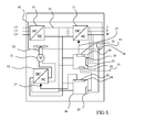
- Figure 1 is a block diagram showing an embodiment wherein a control unit of a cooling frequency converter controls a power unit;
- FIG. 2 is a block diagram showing an arrangement according to the embodiment shown in Figure 1, wherein the control unit controls an inverter in order to control a three-phase short circuit motor;
- FIG 3 is a block diagram showing an arrangement according to the embodiment shown in Figure 1, wherein the control unit controls the inverter in order to control a single-phase short circuit motor, and
- FIG 4 is a block diagram showing an arrangement according to the embodiment shown in Figure 1, wherein the control unit controls a switched-mode power supply in order to control a DC motor.
- a frequency converter comprises a power part 10 comprising a rectifier 11, an intermediate circuit 12 and an inverter 13.
- the frequency converter further includes a control part 20, connected to the power part 10.
- the power part 10 and the control part 20 are connected to measurement means 15 for providing measurement information 28 from the power part 10.
- the control part 20 comprises means 21 for receiving control information 22 supplied thereto, and means 23 for receiving measurement information, means 24 for producing adjustment information 27 by utilizing the received measurement information 28 and the supplied control information, and means 25 for transmitting the adjustment information 27 to the inverter 13 for controlling it.
- These means are I/O connections of frequency converters.
- the connections may be analogue or digital.
- the measurement information and the adjustment information may be e.g. current signals or voltage signals.
- a bus-type solution, such as Modbus or Profi bus, may also be used for delivering the measurement information and the adjustment information.
- the frequency converter also comprises cooling means, including a cooling motor 31 and a transfer means 32 for producing cooling.
- a cooling frequency converter is arranged in connection with the frequency converter to control the cooling means, the power part 10 of the cooling frequency converter comprising a rectifier 11 of the frequency converter and an intermediate circuit 12 of the frequency converter as well as a unique power unit 43 of the cooling frequency converter, the power unit 43 being arranged between the intermediate circuit 12 and the cooling motor 31 in order to supply power to the cooling motor 31, the cooling frequency converter having a control unit 50 connected to the power unit 43 and controlling the same.
- the control unit 50 of the cooling frequency converter is connected to the control part 20 of the frequency converter for delivering the measurement information 28 and the control information 22 from the control part 20 to the control unit 50.
- the control unit 50 comprises reception means 53, such as I/O means or bus-type connections, for receiving the measurement information 28 and the control information 22, as well as control means 54 for producing adjustment information 57 on the basis of the received measurement information 28 and control information 22.
- reception means 53 such as I/O means or bus-type connections
- control means 54 for producing adjustment information 57 on the basis of the received measurement information 28 and control information 22.
- the control means 54 may implement the adjustment information 57 to adjust cooling nonlinearly when it is desired to achieve a predetermined temperature, and the cooling may be adjusted anticipatorily based on the forthcoming but already known control information 22.
- the control unit further comprises transmission means 55 for transmitting this adjustment information 57 to the power unit 43 for controlling the same.
- Power is supplied to the control unit 50 from the intermediate circuit 12 of the power part.
- the power supply of the control part may also be an external power supply, such as a battery. This enables the control part to be used also when the rest of the device is without power.
- FIGS 2 and 3 show an embodiment wherein the power unit 43 of the cooling frequency converter is an inverter controlled by adjustment information 57.
- Pulse Width Modulation for instance, may be used for controlling the inverter, in which case both the voltage and the frequency of the output of the inverter are controlled by a PWM control.
- the intermediate circuit 12 has a constant full voltage, and the voltage going to the cooling motor 31 is adjusted by cutting the voltage pulse supplied thereto such that the voltage of the motor is suitable with respect to the frequency.
- the cooling motor may be an AC motor.
- a three-phase short circuit motor is shown as the cooling motor 31, and in Figure 3, the cooling motor 31 is a single-phase short circuit motor.
- FIG 4 shows an arrangement comprising a control unit 50 controlling a power unit 43, such as a switched-mode power supply, for controlling a DC motor 31.
- the DC motor 31 is preferably a permanent magnet motor but it may equally well be an iron-free DC motor or a brushless DC motor.
- a permanent magnet motor has quite a good efficiency so that at low load it does not in itself cause a very large amount of lost capacity and thus generate heat inside the housing.
- the speed of rotation of a permanent magnet motor is directly proportional to a control voltage, so it is thus quite easy to control.
Landscapes
- Engineering & Computer Science (AREA)
- Power Engineering (AREA)
- Inverter Devices (AREA)
- Control Of Ac Motors In General (AREA)
- Control Of Electric Motors In General (AREA)
Abstract
Description
- The invention relates to a cooling arrangement in a frequency converter.
- A frequency converter is a power electronics device for steplessly adjusting the rotation speed of an alternating-current motor, such as a short circuit motor. The rotation speed of a short circuit motor is proportional to frequency, so by steplessly changing the frequency of a motor its rotation speed changes correspondingly. A frequency converter may be used for adjusting the acceleration and deceleration as well as the braking and reversing of a motor. Based on its function, a frequency converter may be divided into four different parts:
- a rectifier for rectifying a received alternating voltage,
- an intermediate circuit for filtering a direct voltage received from the rectifier,
- an inverter for changing the rectified and filtered voltage back to an alternating voltage, and
- a control unit for controlling the operation of the inverter on the basis of received measurement information to enable a correct frequency to be provided for the voltage to be fed to a motor.
- In such frequency converters power loss occurs, causing by such lost capacity a large amount of heat that should be removed in order to protect the components of the frequency converters. The demand for cooling air of frequency converters varies considerably: for small frequency converters 70 m3/h may suffice, but the demand increases significantly, the largest frequency converters requiring up to 8000 m3/h. In order to protect the frequency converters a transfer means, e.g. a blower, is used, which is arranged to conduct the heat generated in a frequency converter to a space surrounding the frequency converter by means of an air flow.
- Previously it has been known to use constant speed fans for cooling electrical devices. This implementation is successful, but the speed of a fan has to be set according to the worst possible situation, which means that the cooling capacity is unnecessarily high. Nowadays a need exists to optimize the efficiency of an electrical device and minimize losses. One way to optimize a device is to try to remove any unnecessary power consumption required for cooling.
- In JP60131094 an attempt is made at this by arranging the motor running a cooling fan together with the motor output. In such a case, the speed of the fan operating as a cooler varies together with the motor output. This results in lesser cooling when the speed of the motor is lower and the device needs less cooling. Higher speeds require more cooling, also the fan rotating quicker. In such a cooling arrangement, however, the cooling capacity has to be dimensioned using a certain safety factor since the surrounding conditions are totally ignored during use. The environmental conditions, e.g. the surrounding temperature, around a device may vary up to 50 degrees (-10° to +40°). In many lower temperature cases the power consumption of such a solution is thus unnecessarily high. Thus, a solution wherein cooling is implemented only on the basis of the motor output of a frequency converter does not take the internal temperatures of the frequency converter into account. Neither does the solution take into account a situation where the load is high even at low revolutions. Devices, for instance lifts, exist that require high cooling capacity even at low speeds.
- An object of the invention is to provide a more accurately adjustable cooling solution for protecting frequency converters producing large amounts of heat while simultaneously optimizing the power consumption required for such protection. The object of the invention is achieved by an arrangement which is characterized by what is disclosed in the independent claim. Preferred embodiments of the invention are disclosed in the dependent claims.
- A cooling arrangement of the invention is based on utilizing components of a power part of a frequency converter as well as measurement and control information from a control part of the frequency converter also in the cooling solution.
- According to the invention, a second frequency converter, a cooling frequency converter, in a sense, is arranged inside a frequency converter, the second frequency converter, however, utilizing both the measurement information measured by the first frequency converter and some of the components of the first frequency converter.
- In the arrangement of the invention, however, in order to enable individual adjustment cooling should have a power unit of its own, such as an inverter which derives its power from an intermediate circuit following a rectifier of a frequency converter. This enables an adjustable cooling arrangement to be implemented by means of as few electrical components as possible.
- The control part of a frequent converter already comprises measurement devices for enabling a motor to be adjusted; in such a case, the measurement devices are used e.g. for carrying out a three-phase measurement on the motor from the outgoing phases, and following the temperature of the frequency converter to protect it. Adjustment information for the cooling devices is obtained from the power part of the frequency converter by means of a measurement device. This adjustment information is already available in existing frequency converter solutions since the existing frequency converters have an integral arrangement for monitoring the temperature of the power part, which is used for protecting the frequency converter against potential overheating. Such a temperature sensing element may be e.g. a temperature detector or a thermostat which indicates to an adjustment circuit the temperature of a target to be measured. In the arrangement of the invention, however, this temperature information may be utilized also as adjustment information for cooling.
- Since the temperature of the environment of a frequency converter may significantly affect the temperatures of the frequency converter, such temperature-measuring measurement information obtained directly from the power part is thus independent of the load and, consequently, more accurate than e.g. adjustment information based on load current measurement or rotation speed.
- Controlling the second power unit by means of a control unit similar to the control part of the frequency converter also enables a nonlinearly operating adjustment to be implemented. This enables the temperature of the power part to be set to a desired level by first cooling the power part less, or not at all, in order to bring the temperature to the desired level.
- On the other hand, utilizing the control information received by the control part in a control unit similar to the control part of the frequency converter enables an anticipatory adjustment to be implemented in cooling. According to the invention, the control unit of a cooling frequency converter comprises means for receiving control information also received by the control part, thus enabling an anticipatory adjustment to be implemented on the basis of this control information by means of the devices in the control unit e.g. by increasing the cooling capacity in advance in order to slow down a temperature rise caused by a forthcoming higher load. This enables hunting in adjustment to be decreased in a continuous adjustment, still enabling a stable temperature simultaneously so that the components are not unnecessarily loaded by large variations in temperature.
- Such an anticipatory adjustment is particularly advantageous in devices that are subjected to heavier loads irregularly, e.g. lift apparatuses. The cooling arrangement of the invention enables an anticipatory adjustment to be carried out e.g. on the basis of lift calls, by raising the cooling level in advance if several lift calls are already known and, on the other hand, possibly lowering the cooling level earlier if no forthcoming lift calls are known.
- Furthermore, in the cooling system of the invention, no separate adjustable cooling is, in turn, needed for a cooling frequency converter since most of the components are shared ones and a fan is used for cooling the frequency converter in its entirety. If necessary, the cooling of the power unit of the cooling frequency converter may be carried out by cooling ribs; due to the light load, the heat production of the power unit is anyway significantly smaller than that of the inverter of the first frequency converter. If necessary, other protecting components, such as a motor overload protection, motor jam protection or an overheat protection for a device, etc., may also be used for protecting the cooling motor's and the cooling frequency converter's own components. Such a release of heat protection means cutting off electricity to a device; consequently, it is mainly for fault situations only.
- In the arrangement of the invention, cooling is provided with a motor and a transfer means, such as a blower or, when using water cooling, a pump-like device, of its own. When extra cooling is needed for one frequency converter, several transfer means may even be arranged in parallel. The connecting points of a cooling motor may also be arranged outside the device, in which case the cooling motor may be placed outside the frequency converter, which means that the cooling motor does not generate heat inside the housing of the frequency converter.
- When the transfer means reside outside the frequency converter, the cooling of the frequency converter may be implemented by an external channelling to the inside of the frequency converter. This enables cooling air to be brought in to the frequency converter also from farther away, e.g. from the cooler outdoor air. On the other hand, such a channelling enables the cooling of even several frequency converters to be implemented by means of one frequency converter controlled, high-power motor and a transfer means connected thereto. Although the adjustment may further be implemented by one control part, measurement information is still needed on all frequency converters by using e.g. a bus-type solution (Modbus, Profibus) for delivering the measurement information. In addition, the adjustment of the transfer means then always has to be implemented according to the largest cooling demand.
- The invention is now described in closer detail in connection with a preferred embodiment and with reference to the accompanying drawings, in which:
- Figure 1 is a block diagram showing an embodiment wherein a control unit of a cooling frequency converter controls a power unit;
- Figure 2 is a block diagram showing an arrangement according to the embodiment shown in Figure 1, wherein the control unit controls an inverter in order to control a three-phase short circuit motor;
- Figure 3 is a block diagram showing an arrangement according to the embodiment shown in Figure 1, wherein the control unit controls the inverter in order to control a single-phase short circuit motor, and
- Figure 4 is a block diagram showing an arrangement according to the embodiment shown in Figure 1, wherein the control unit controls a switched-mode power supply in order to control a DC motor.
- According to Figures 1 to 4, in a cooling arrangement a frequency converter comprises a
power part 10 comprising arectifier 11, anintermediate circuit 12 and aninverter 13. The frequency converter further includes acontrol part 20, connected to thepower part 10. - Furthermore, according to Figures 1 to 4, the
power part 10 and thecontrol part 20 are connected to measurement means 15 for providingmeasurement information 28 from thepower part 10. - The
control part 20 comprises means 21 for receivingcontrol information 22 supplied thereto, and means 23 for receiving measurement information, means 24 for producingadjustment information 27 by utilizing the receivedmeasurement information 28 and the supplied control information, and means 25 for transmitting theadjustment information 27 to theinverter 13 for controlling it. These means are I/O connections of frequency converters. The connections may be analogue or digital. The measurement information and the adjustment information may be e.g. current signals or voltage signals. A bus-type solution, such as Modbus or Profi bus, may also be used for delivering the measurement information and the adjustment information. - The frequency converter also comprises cooling means, including a cooling
motor 31 and a transfer means 32 for producing cooling. A cooling frequency converter is arranged in connection with the frequency converter to control the cooling means, thepower part 10 of the cooling frequency converter comprising arectifier 11 of the frequency converter and anintermediate circuit 12 of the frequency converter as well as aunique power unit 43 of the cooling frequency converter, thepower unit 43 being arranged between theintermediate circuit 12 and the coolingmotor 31 in order to supply power to the coolingmotor 31, the cooling frequency converter having acontrol unit 50 connected to thepower unit 43 and controlling the same. - The
control unit 50 of the cooling frequency converter is connected to thecontrol part 20 of the frequency converter for delivering themeasurement information 28 and thecontrol information 22 from thecontrol part 20 to thecontrol unit 50. Thecontrol unit 50 comprises reception means 53, such as I/O means or bus-type connections, for receiving themeasurement information 28 and thecontrol information 22, as well as control means 54 for producingadjustment information 57 on the basis of the receivedmeasurement information 28 and controlinformation 22. On the basis of themeasurement information 28 and thecontrol information 22 the control means 54 may implement theadjustment information 57 to adjust cooling nonlinearly when it is desired to achieve a predetermined temperature, and the cooling may be adjusted anticipatorily based on the forthcoming but already knowncontrol information 22. The control unit further comprises transmission means 55 for transmitting thisadjustment information 57 to thepower unit 43 for controlling the same. - Power is supplied to the
control unit 50 from theintermediate circuit 12 of the power part. The power supply of the control part may also be an external power supply, such as a battery. This enables the control part to be used also when the rest of the device is without power. - Figures 2 and 3 show an embodiment wherein the
power unit 43 of the cooling frequency converter is an inverter controlled byadjustment information 57. Pulse Width Modulation (PWM), for instance, may be used for controlling the inverter, in which case both the voltage and the frequency of the output of the inverter are controlled by a PWM control. Then, theintermediate circuit 12 has a constant full voltage, and the voltage going to the coolingmotor 31 is adjusted by cutting the voltage pulse supplied thereto such that the voltage of the motor is suitable with respect to the frequency. - When an inverter is used as the power unit, the cooling motor may be an AC motor. In Figure 2, a three-phase short circuit motor is shown as the cooling
motor 31, and in Figure 3, the coolingmotor 31 is a single-phase short circuit motor. - Figure 4 shows an arrangement comprising a
control unit 50 controlling apower unit 43, such as a switched-mode power supply, for controlling aDC motor 31. TheDC motor 31 is preferably a permanent magnet motor but it may equally well be an iron-free DC motor or a brushless DC motor. A permanent magnet motor has quite a good efficiency so that at low load it does not in itself cause a very large amount of lost capacity and thus generate heat inside the housing. The speed of rotation of a permanent magnet motor is directly proportional to a control voltage, so it is thus quite easy to control. - It is obvious to one skilled in the art that as technology advances, the basic idea of the invention can be implemented in many different ways. The invention and its embodiments are thus not restricted to the examples described above but may vary within the scope of the claims.
Claims (10)
- A cooling arrangement in a frequency converter, the arrangement being configured to convey heat generated at the frequency converter to a space surrounding the frequency converter, comprising:- a power part (10) of the frequency converter, comprising a rectifier (11), an intermediate circuit (12) and an inverter (13),- a control part (20) of the frequency converter, connected to the power part (10),- measurement means (15) connected to the power part (10) and to the control part (20) for producing measurement information from the power part, and- the control part (20) comprising means (21) for receiving control information (22) supplied thereto and means (23) for receiving measurement information (28), means (24) for producing adjustment information (27) by utilizing the received measurement information (28) and the supplied control information (22), and means (25) for transmitting this adjustment information (27) to the inverter (13) for controlling it, and- cooling means comprising a cooling motor (31) and a transfer means (32) for producing cooling, characterized in that in the arrangement:a cooling frequency converter is arranged in connection with the frequency converter to control the cooling means, the power part of the cooling frequency converter comprising a rectifier (11) of the frequency converter and an intermediate circuit (12) of the frequency converter, as well as a unique power unit (43) of the cooling frequency converter, the power unit (43) being arranged between the intermediate circuit (12) and the cooling motor (31) in order to supply power the cooling motor (31), the cooling frequency converter having a control unit (50) connected to the power unit (43) and controlling the same.
- A cooling arrangement as claimed in claim 1, characterized in that the control unit (50) of the cooling frequency converter is connected to the control part (20) of the frequency converter for delivering the measurement information (28) and control information (22) received by the control part from the control part (20) to the control unit (50), which comprises reception means (53) for receiving the measurement information (28) and the control information (22), and control means (54) for producing adjustment information (57) on the basis of the received measurement information (28) and control information (22), and transmission means (55) for transmitting this adjustment information (57) to the power unit (43) for controlling the same.
- A cooling arrangement as claimed in claims 1 and 2, characterizedin that the cooling motor (31) is a DC motor.
- A cooling arrangement as claimed in claim 3, characterized in that the cooling motor (31) is a permanent magnet motor.
- A cooling arrangement as claimed in any one of the preceding claims, characterized in that the power unit (43) is a switched-mode power supply.
- A cooling arrangement as claimed in claims 1 and 2, characterized in that the cooling motor (31) is an AC motor.
- A cooling arrangement as claimed in claim 6, characterized in that the power unit (43) is an inverter.
- A cooling arrangement as claimed in any one of the preceding claims, characterized in that the adjustment information (57) comprises a PWM control.
- A cooling arrangement as claimed in any one of the preceding claims, characterized in that the transfer means (32) is a blower.
- A cooling arrangement as claimed in any one of claims 1 to 8, characterized in that the transfer means (32) is a pump.
Applications Claiming Priority (2)
| Application Number | Priority Date | Filing Date | Title |
|---|---|---|---|
| FI20021856A FI118661B (en) | 2002-10-17 | 2002-10-17 | Cooling arrangement in the drive |
| FI20021856 | 2002-10-17 |
Publications (3)
| Publication Number | Publication Date |
|---|---|
| EP1414284A2 true EP1414284A2 (en) | 2004-04-28 |
| EP1414284A3 EP1414284A3 (en) | 2005-07-13 |
| EP1414284B1 EP1414284B1 (en) | 2013-04-24 |
Family
ID=8564779
Family Applications (1)
| Application Number | Title | Priority Date | Filing Date |
|---|---|---|---|
| EP03103771.6A Expired - Lifetime EP1414284B1 (en) | 2002-10-17 | 2003-10-13 | Cooling arrangement in frequency converter |
Country Status (3)
| Country | Link |
|---|---|
| US (1) | US7023712B2 (en) |
| EP (1) | EP1414284B1 (en) |
| FI (1) | FI118661B (en) |
Cited By (1)
| Publication number | Priority date | Publication date | Assignee | Title |
|---|---|---|---|---|
| WO2007038846A1 (en) * | 2005-10-03 | 2007-04-12 | Eduardo Pedrosa Santos | System to control, protect and monitor the status of forced cooling motors for power transformers and similar |
Families Citing this family (9)
| Publication number | Priority date | Publication date | Assignee | Title |
|---|---|---|---|---|
| JP4796841B2 (en) * | 2005-12-28 | 2011-10-19 | 株式会社日立産機システム | Power converter and control method thereof |
| FI121563B (en) * | 2006-09-22 | 2010-12-31 | Abb Oy | inverter |
| FI121613B (en) * | 2006-12-21 | 2011-01-31 | Abb Oy | Procedure and system for motor supplied with voltage intermediate frequency converter |
| US8482163B2 (en) * | 2009-05-15 | 2013-07-09 | First Solar, Inc. | Inverter cooler |
| US8243446B2 (en) * | 2010-03-11 | 2012-08-14 | First Solar, Inc. | Photovoltaic inverter |
| DE102012008873A1 (en) * | 2012-05-03 | 2013-11-07 | Robert Bosch Gmbh | Device for ventilating e.g. direct voltage/alternating voltage transducer for electric motor, has intermediate circuits connected between power electronics and fan to supply fan with electric power, where fan ventilates power electronics |
| DE102013004337A1 (en) * | 2013-03-14 | 2014-09-18 | Wilo Se | Electric motor with power electronic converter system and active cooling device fed from it |
| CN104519715A (en) * | 2013-09-30 | 2015-04-15 | 施耐德东芝换流器欧洲公司 | Heat radiation structure of variable speed drive equipment and control method and equipment |
| CN105981281B (en) * | 2013-12-03 | 2018-12-07 | 三菱电机株式会社 | Power conversion device |
Citations (3)
| Publication number | Priority date | Publication date | Assignee | Title |
|---|---|---|---|---|
| JPS60131094A (en) | 1983-12-20 | 1985-07-12 | Mitsubishi Electric Corp | Variable voltage variable frequency power source |
| US5825642A (en) | 1996-11-08 | 1998-10-20 | Sansha Electric Manufacuring Co. Limited | Power supply apparatus |
| US6278080B1 (en) | 1998-11-26 | 2001-08-21 | Sansha Electric Manufacturing Company Limited | Power supply apparatus |
Family Cites Families (7)
| Publication number | Priority date | Publication date | Assignee | Title |
|---|---|---|---|---|
| EP0655881A1 (en) * | 1993-11-26 | 1995-05-31 | Siemens Aktiengesellschaft | Casing |
| US6236184B1 (en) * | 1998-12-23 | 2001-05-22 | Hamilton Sundstrand Corporation | Variable speed cooling fan control |
| DE19932721C1 (en) | 1999-07-16 | 2001-01-18 | Eppendorf Geraetebau Netheler | Laboratory centrifuge with cooling unit |
| US6268664B1 (en) * | 1999-10-08 | 2001-07-31 | Sun Microsystems, Inc. | Fan control module for a system unit |
| US6198642B1 (en) * | 1999-10-19 | 2001-03-06 | Tracewell Power, Inc. | Compact multiple output power supply |
| US6188189B1 (en) * | 1999-12-23 | 2001-02-13 | Analog Devices, Inc. | Fan speed control system |
| DE10153748A1 (en) * | 2001-10-31 | 2003-05-22 | Siemens Ag | Converter unit in modular design |
-
2002
- 2002-10-17 FI FI20021856A patent/FI118661B/en not_active IP Right Cessation
-
2003
- 2003-10-13 EP EP03103771.6A patent/EP1414284B1/en not_active Expired - Lifetime
- 2003-10-14 US US10/683,278 patent/US7023712B2/en not_active Expired - Fee Related
Patent Citations (3)
| Publication number | Priority date | Publication date | Assignee | Title |
|---|---|---|---|---|
| JPS60131094A (en) | 1983-12-20 | 1985-07-12 | Mitsubishi Electric Corp | Variable voltage variable frequency power source |
| US5825642A (en) | 1996-11-08 | 1998-10-20 | Sansha Electric Manufacuring Co. Limited | Power supply apparatus |
| US6278080B1 (en) | 1998-11-26 | 2001-08-21 | Sansha Electric Manufacturing Company Limited | Power supply apparatus |
Cited By (1)
| Publication number | Priority date | Publication date | Assignee | Title |
|---|---|---|---|---|
| WO2007038846A1 (en) * | 2005-10-03 | 2007-04-12 | Eduardo Pedrosa Santos | System to control, protect and monitor the status of forced cooling motors for power transformers and similar |
Also Published As
| Publication number | Publication date |
|---|---|
| US20040119439A1 (en) | 2004-06-24 |
| FI20021856L (en) | 2004-04-18 |
| FI118661B (en) | 2008-01-31 |
| EP1414284B1 (en) | 2013-04-24 |
| EP1414284A3 (en) | 2005-07-13 |
| US7023712B2 (en) | 2006-04-04 |
| FI20021856A0 (en) | 2002-10-17 |
Similar Documents
| Publication | Publication Date | Title |
|---|---|---|
| US8558491B2 (en) | Inverter controller and refrigerating and air-conditioning unit | |
| CN100334802C (en) | Frequency converters for different supply voltages | |
| CN108292902B (en) | Hybrid drive circuit and control method for variable speed induction motor system | |
| US10924055B2 (en) | Motor drive apparatus having input power supply voltage adjustment function | |
| US5770909A (en) | Wound rotor synchronous motor-generator and field control system therefor | |
| US6801013B2 (en) | PSC motor system for use in HVAC applications | |
| CN107154771B (en) | Fan frequency conversion speed regulation system for power electronic converter | |
| US5126642A (en) | Variable speed motor control | |
| EP2169819B1 (en) | Vehicle power generating device and an alternator control method | |
| US7023712B2 (en) | Cooling arrangement in frequency converter | |
| RU2502614C1 (en) | Power plant control device | |
| GB2401203A (en) | Thermal protection system for high output vehicle alternator | |
| JP2003348892A (en) | Control device for multiple motors, power conversion device, inverter module, converter module | |
| US7733048B2 (en) | Method and arrangement in connection with motor fed with frequency converter provided with intermediate voltage circuit | |
| CN113969897A (en) | Control system for fluid management system | |
| WO2006114843A1 (en) | Servo motor controller | |
| KR101278728B1 (en) | Circuit controlling rotor current of of synchro generator | |
| JP6146316B2 (en) | Air conditioner | |
| JPH10174276A (en) | Motor protection device | |
| EP3667078B1 (en) | Dynamic control of trip temperature for power module | |
| US7609010B2 (en) | Inverter | |
| JP2002199787A (en) | Cooling air volume adjustment device for blower | |
| CN115885135A (en) | Motor and method of use | |
| JPH06319264A (en) | Inverter controller | |
| US20070024224A1 (en) | kW-based torque control for AC motors |
Legal Events
| Date | Code | Title | Description |
|---|---|---|---|
| PUAI | Public reference made under article 153(3) epc to a published international application that has entered the european phase |
Free format text: ORIGINAL CODE: 0009012 |
|
| AK | Designated contracting states |
Kind code of ref document: A2 Designated state(s): AT BE BG CH CY CZ DE DK EE ES FI FR GB GR HU IE IT LI LU MC NL PT RO SE SI SK TR |
|
| AX | Request for extension of the european patent |
Extension state: AL LT LV MK |
|
| PUAL | Search report despatched |
Free format text: ORIGINAL CODE: 0009013 |
|
| AK | Designated contracting states |
Kind code of ref document: A3 Designated state(s): AT BE BG CH CY CZ DE DK EE ES FI FR GB GR HU IE IT LI LU MC NL PT RO SE SI SK TR |
|
| AX | Request for extension of the european patent |
Extension state: AL LT LV MK |
|
| 17P | Request for examination filed |
Effective date: 20051117 |
|
| AKX | Designation fees paid |
Designated state(s): AT BE BG CH CY CZ DE DK EE ES FI FR GB GR HU IE IT LI LU MC NL PT RO SE SI SK TR |
|
| 17Q | First examination report despatched |
Effective date: 20110524 |
|
| GRAP | Despatch of communication of intention to grant a patent |
Free format text: ORIGINAL CODE: EPIDOSNIGR1 |
|
| RIN1 | Information on inventor provided before grant (corrected) |
Inventor name: MIETTINEN, OSMO |
|
| GRAS | Grant fee paid |
Free format text: ORIGINAL CODE: EPIDOSNIGR3 |
|
| GRAA | (expected) grant |
Free format text: ORIGINAL CODE: 0009210 |
|
| AK | Designated contracting states |
Kind code of ref document: B1 Designated state(s): AT BE BG CH CY CZ DE DK EE ES FI FR GB GR HU IE IT LI LU MC NL PT RO SE SI SK TR |
|
| REG | Reference to a national code |
Ref country code: GB Ref legal event code: FG4D |
|
| REG | Reference to a national code |
Ref country code: CH Ref legal event code: EP |
|
| REG | Reference to a national code |
Ref country code: AT Ref legal event code: REF Ref document number: 609269 Country of ref document: AT Kind code of ref document: T Effective date: 20130515 |
|
| REG | Reference to a national code |
Ref country code: IE Ref legal event code: FG4D |
|
| REG | Reference to a national code |
Ref country code: DE Ref legal event code: R096 Ref document number: 60343854 Country of ref document: DE Effective date: 20130620 |
|
| REG | Reference to a national code |
Ref country code: AT Ref legal event code: MK05 Ref document number: 609269 Country of ref document: AT Kind code of ref document: T Effective date: 20130424 |
|
| REG | Reference to a national code |
Ref country code: NL Ref legal event code: VDEP Effective date: 20130424 |
|
| PG25 | Lapsed in a contracting state [announced via postgrant information from national office to epo] |
Ref country code: PT Free format text: LAPSE BECAUSE OF FAILURE TO SUBMIT A TRANSLATION OF THE DESCRIPTION OR TO PAY THE FEE WITHIN THE PRESCRIBED TIME-LIMIT Effective date: 20130826 Ref country code: SE Free format text: LAPSE BECAUSE OF FAILURE TO SUBMIT A TRANSLATION OF THE DESCRIPTION OR TO PAY THE FEE WITHIN THE PRESCRIBED TIME-LIMIT Effective date: 20130424 Ref country code: SI Free format text: LAPSE BECAUSE OF FAILURE TO SUBMIT A TRANSLATION OF THE DESCRIPTION OR TO PAY THE FEE WITHIN THE PRESCRIBED TIME-LIMIT Effective date: 20130424 Ref country code: GR Free format text: LAPSE BECAUSE OF FAILURE TO SUBMIT A TRANSLATION OF THE DESCRIPTION OR TO PAY THE FEE WITHIN THE PRESCRIBED TIME-LIMIT Effective date: 20130725 Ref country code: ES Free format text: LAPSE BECAUSE OF FAILURE TO SUBMIT A TRANSLATION OF THE DESCRIPTION OR TO PAY THE FEE WITHIN THE PRESCRIBED TIME-LIMIT Effective date: 20130804 Ref country code: AT Free format text: LAPSE BECAUSE OF FAILURE TO SUBMIT A TRANSLATION OF THE DESCRIPTION OR TO PAY THE FEE WITHIN THE PRESCRIBED TIME-LIMIT Effective date: 20130424 Ref country code: BE Free format text: LAPSE BECAUSE OF FAILURE TO SUBMIT A TRANSLATION OF THE DESCRIPTION OR TO PAY THE FEE WITHIN THE PRESCRIBED TIME-LIMIT Effective date: 20130424 Ref country code: FI Free format text: LAPSE BECAUSE OF FAILURE TO SUBMIT A TRANSLATION OF THE DESCRIPTION OR TO PAY THE FEE WITHIN THE PRESCRIBED TIME-LIMIT Effective date: 20130424 |
|
| PG25 | Lapsed in a contracting state [announced via postgrant information from national office to epo] |
Ref country code: CY Free format text: LAPSE BECAUSE OF FAILURE TO SUBMIT A TRANSLATION OF THE DESCRIPTION OR TO PAY THE FEE WITHIN THE PRESCRIBED TIME-LIMIT Effective date: 20130424 Ref country code: BG Free format text: LAPSE BECAUSE OF FAILURE TO SUBMIT A TRANSLATION OF THE DESCRIPTION OR TO PAY THE FEE WITHIN THE PRESCRIBED TIME-LIMIT Effective date: 20130724 |
|
| PG25 | Lapsed in a contracting state [announced via postgrant information from national office to epo] |
Ref country code: DK Free format text: LAPSE BECAUSE OF FAILURE TO SUBMIT A TRANSLATION OF THE DESCRIPTION OR TO PAY THE FEE WITHIN THE PRESCRIBED TIME-LIMIT Effective date: 20130424 Ref country code: EE Free format text: LAPSE BECAUSE OF FAILURE TO SUBMIT A TRANSLATION OF THE DESCRIPTION OR TO PAY THE FEE WITHIN THE PRESCRIBED TIME-LIMIT Effective date: 20130424 Ref country code: SK Free format text: LAPSE BECAUSE OF FAILURE TO SUBMIT A TRANSLATION OF THE DESCRIPTION OR TO PAY THE FEE WITHIN THE PRESCRIBED TIME-LIMIT Effective date: 20130424 Ref country code: CZ Free format text: LAPSE BECAUSE OF FAILURE TO SUBMIT A TRANSLATION OF THE DESCRIPTION OR TO PAY THE FEE WITHIN THE PRESCRIBED TIME-LIMIT Effective date: 20130424 |
|
| PG25 | Lapsed in a contracting state [announced via postgrant information from national office to epo] |
Ref country code: IT Free format text: LAPSE BECAUSE OF FAILURE TO SUBMIT A TRANSLATION OF THE DESCRIPTION OR TO PAY THE FEE WITHIN THE PRESCRIBED TIME-LIMIT Effective date: 20130424 Ref country code: RO Free format text: LAPSE BECAUSE OF FAILURE TO SUBMIT A TRANSLATION OF THE DESCRIPTION OR TO PAY THE FEE WITHIN THE PRESCRIBED TIME-LIMIT Effective date: 20130424 Ref country code: NL Free format text: LAPSE BECAUSE OF FAILURE TO SUBMIT A TRANSLATION OF THE DESCRIPTION OR TO PAY THE FEE WITHIN THE PRESCRIBED TIME-LIMIT Effective date: 20130424 |
|
| PLBE | No opposition filed within time limit |
Free format text: ORIGINAL CODE: 0009261 |
|
| STAA | Information on the status of an ep patent application or granted ep patent |
Free format text: STATUS: NO OPPOSITION FILED WITHIN TIME LIMIT |
|
| 26N | No opposition filed |
Effective date: 20140127 |
|
| REG | Reference to a national code |
Ref country code: DE Ref legal event code: R097 Ref document number: 60343854 Country of ref document: DE Effective date: 20140127 |
|
| PG25 | Lapsed in a contracting state [announced via postgrant information from national office to epo] |
Ref country code: MC Free format text: LAPSE BECAUSE OF FAILURE TO SUBMIT A TRANSLATION OF THE DESCRIPTION OR TO PAY THE FEE WITHIN THE PRESCRIBED TIME-LIMIT Effective date: 20130424 |
|
| REG | Reference to a national code |
Ref country code: CH Ref legal event code: PL |
|
| GBPC | Gb: european patent ceased through non-payment of renewal fee |
Effective date: 20131013 |
|
| REG | Reference to a national code |
Ref country code: IE Ref legal event code: MM4A |
|
| PG25 | Lapsed in a contracting state [announced via postgrant information from national office to epo] |
Ref country code: CH Free format text: LAPSE BECAUSE OF NON-PAYMENT OF DUE FEES Effective date: 20131031 Ref country code: LI Free format text: LAPSE BECAUSE OF NON-PAYMENT OF DUE FEES Effective date: 20131031 Ref country code: GB Free format text: LAPSE BECAUSE OF NON-PAYMENT OF DUE FEES Effective date: 20131013 |
|
| REG | Reference to a national code |
Ref country code: FR Ref legal event code: ST Effective date: 20140630 |
|
| REG | Reference to a national code |
Ref country code: DE Ref legal event code: R119 Ref document number: 60343854 Country of ref document: DE Effective date: 20140501 |
|
| PG25 | Lapsed in a contracting state [announced via postgrant information from national office to epo] |
Ref country code: FR Free format text: LAPSE BECAUSE OF NON-PAYMENT OF DUE FEES Effective date: 20131031 Ref country code: DE Free format text: LAPSE BECAUSE OF NON-PAYMENT OF DUE FEES Effective date: 20140501 |
|
| PG25 | Lapsed in a contracting state [announced via postgrant information from national office to epo] |
Ref country code: IE Free format text: LAPSE BECAUSE OF NON-PAYMENT OF DUE FEES Effective date: 20131013 |
|
| PG25 | Lapsed in a contracting state [announced via postgrant information from national office to epo] |
Ref country code: TR Free format text: LAPSE BECAUSE OF FAILURE TO SUBMIT A TRANSLATION OF THE DESCRIPTION OR TO PAY THE FEE WITHIN THE PRESCRIBED TIME-LIMIT Effective date: 20130424 |
|
| PG25 | Lapsed in a contracting state [announced via postgrant information from national office to epo] |
Ref country code: HU Free format text: LAPSE BECAUSE OF FAILURE TO SUBMIT A TRANSLATION OF THE DESCRIPTION OR TO PAY THE FEE WITHIN THE PRESCRIBED TIME-LIMIT; INVALID AB INITIO Effective date: 20031013 Ref country code: LU Free format text: LAPSE BECAUSE OF NON-PAYMENT OF DUE FEES Effective date: 20131013 |