EP1414179A1 - A method for determining packet error rate of wireless LAN stations - Google Patents
A method for determining packet error rate of wireless LAN stations Download PDFInfo
- Publication number
- EP1414179A1 EP1414179A1 EP20030103912 EP03103912A EP1414179A1 EP 1414179 A1 EP1414179 A1 EP 1414179A1 EP 20030103912 EP20030103912 EP 20030103912 EP 03103912 A EP03103912 A EP 03103912A EP 1414179 A1 EP1414179 A1 EP 1414179A1
- Authority
- EP
- European Patent Office
- Prior art keywords
- packet
- card
- wireless lan
- error rate
- test data
- Prior art date
- Legal status (The legal status is an assumption and is not a legal conclusion. Google has not performed a legal analysis and makes no representation as to the accuracy of the status listed.)
- Withdrawn
Links
- 238000000034 method Methods 0.000 title claims description 16
- 238000012360 testing method Methods 0.000 claims abstract description 80
- 239000000523 sample Substances 0.000 claims description 6
- 230000004044 response Effects 0.000 claims description 2
- 238000004891 communication Methods 0.000 description 5
- 230000006870 function Effects 0.000 description 4
- 230000008569 process Effects 0.000 description 3
- 239000000463 material Substances 0.000 description 2
- 238000012986 modification Methods 0.000 description 2
- 230000004048 modification Effects 0.000 description 2
- 238000000060 site-specific infrared dichroism spectroscopy Methods 0.000 description 2
- 230000008901 benefit Effects 0.000 description 1
- 230000005540 biological transmission Effects 0.000 description 1
- 230000008878 coupling Effects 0.000 description 1
- 238000010168 coupling process Methods 0.000 description 1
- 238000005859 coupling reaction Methods 0.000 description 1
- 230000000694 effects Effects 0.000 description 1
- 238000005516 engineering process Methods 0.000 description 1
- 230000003993 interaction Effects 0.000 description 1
- 230000000191 radiation effect Effects 0.000 description 1
Images

Classifications
-
- H—ELECTRICITY
- H04—ELECTRIC COMMUNICATION TECHNIQUE
- H04L—TRANSMISSION OF DIGITAL INFORMATION, e.g. TELEGRAPHIC COMMUNICATION
- H04L1/00—Arrangements for detecting or preventing errors in the information received
- H04L1/24—Testing correct operation
- H04L1/242—Testing correct operation by comparing a transmitted test signal with a locally generated replica
- H04L1/243—Testing correct operation by comparing a transmitted test signal with a locally generated replica at the transmitter, using a loop-back
-
- H—ELECTRICITY
- H04—ELECTRIC COMMUNICATION TECHNIQUE
- H04L—TRANSMISSION OF DIGITAL INFORMATION, e.g. TELEGRAPHIC COMMUNICATION
- H04L1/00—Arrangements for detecting or preventing errors in the information received
- H04L1/20—Arrangements for detecting or preventing errors in the information received using signal quality detector
-
- H—ELECTRICITY
- H04—ELECTRIC COMMUNICATION TECHNIQUE
- H04L—TRANSMISSION OF DIGITAL INFORMATION, e.g. TELEGRAPHIC COMMUNICATION
- H04L1/00—Arrangements for detecting or preventing errors in the information received
- H04L1/12—Arrangements for detecting or preventing errors in the information received by using return channel
- H04L1/16—Arrangements for detecting or preventing errors in the information received by using return channel in which the return channel carries supervisory signals, e.g. repetition request signals
Definitions
- the present invention generally relates to a method of determining packet error rates of wireless stations. More particularly, the invention relates to a method of determining packet error rates in the face of varying degrees of noise for any manufacturer's wireless local area network (“WLAN”) station.
- WLAN wireless local area network
- data packets are transmitted across the network infrastructure from one node to another.
- a packet that is sent from a source node to a destination node is not always received by the destination node accurately.
- One or more bits may have flipped state (i.e., a logic "1” may have turned into a logic "0", and vice versa).
- This problem is particularly significant for wireless networks (e.g., IEEE 802.11 networks). Communications across a wireless medium are particularly susceptible to noise generated by equipment external to the wireless network.
- wireless networks include two or more wireless stations capable of wirelessly communicating with one another.
- a typical architecture of such a wireless network includes one or more access points ("APs") each of which is associated with one or more wireless stations.
- a wireless station that is not an AP, may comprise a portable computer that includes a wireless local area network (“LAN”) card.
- the wireless LAN card may be provided by any one of a variety of manufacturers and includes one or more antennas and other electronics that control the operation of the wireless capability of the station.
- Most wireless networks include the ability to detect packet transmission errors and correct the error. For example, in an 802.11 network for each data packet transmitted to a destination station, the destination station transmits an acknowledgment packet back to the source station.
- the acknowledgment packet lets the source station know that the original data packet was correctly received by the destination station. If an acknowledgment packet is not received by the source station with in a predetermined period of time, the source station determines that an error occurred preventing the packet from being correctly received by the destination station. The source station then resends the original data packet with the expectation that the retransmitted data packet will be correctly received by the destination station. Because packet errors are often dealt with by retransmitting the packet, packet errors slow down the operation of the network and thus are highly undesirable.
- the PER is defined as the percentage of packets sent to a station that are not correctly received. For example, if out of 100 packets, 98 are correctly received and 2 are not, the PER is 2%.
- Each manufacturer of wireless cards generally knows the PER of its own wireless cards, but may not know the PER of its competitors' wireless cards-the PER may be a parameter that a manufacturer does not make widely known. Even if a manufacturer did reveal its PER to the public, the PER is generally a function of the amount of noise present in the environment in which the wireless station is operating. That is, a higher level of noise generally causes more packets to be lost due to errors. Consequently, the PER of a wireless station generally increases with increasing levels of noise. As such, it would be desirable to compare PERs of various wireless cards as a function of noise level.
- the wireless card under test is placed inside an anechoic chamber.
- Test equipment some of which may also be inside the chamber emulates an access point and the card under test "associates" itself with the emulated access point.
- the test equipment preferably includes an arbitrary waveform generator, RF signal generator, a computer through which an operator controls the system, and a controller which emulates an access point. The controller commands the arbitrary waveform generator and RF signal generator to transmit a test data packet to the card under test.
- the card transmits back an acknowledgment packet in accordance with the wireless standard to which it was designed (e.g., IEEE 802.11).
- the controller determines which test data packets are received by the test card and which are lost by "listening" for the acknowledgment packets. An absence of an acknowledgement packet indicates a lost test data packet.
- the controller then can compute the packet error rate by dividing the number of lost packets by the total number of test data packets sent (and multiplying by 100 to convert to a percentage value if desired).
- the RF signal generator introduces a desired amount of noise into the test data packet. This permits the operator to determine the test card's packet error rate based on varying levels of noise.
- a preferred embodiment of determining the packet error rate of a wireless LAN card comprises (a) emulating an access point; (b) transmitting a data packet; (c) determining whether an acknowledgment packet has been received; (d) if an acknowledgment packet is not received, determining that the data packet has been lost; (e) if an acknowledgment packet is received, determining that the data packet has not been lost; (f) repeating (b)-(e) a predetermined number of times; and (g) computing a packet error rate based on the number of data packets determined to be lost relative to the number of data packets transmitted in (b).
- the preferred embodiments described herein permit the packet error rates of a variety of wireless cards to be determined and then compared against one another. This information is useful to wireless card manufacturers in their continued attempts to improve wireless technology.
- system 100 includes an anechoic chamber 102 in which a WLAN card under test 106 is placed for testing to determine the card's packet error rate in the face of varying levels of noise.
- Anechoic chambers are well known in the art as rooms which are lined with a material that absorbs radio waves over a range of frequencies. Externally produced radio frequency (“RF") energy thus is not permitted to penetrate the chamber to reach the WLAN card under test 106 and other equipment contained therein. Further still, any RF energy generated by the equipment inside the chamber 102 radiates outward and is absorbed by the material lining the inside walls of the chamber and thus is not reflected thereby minimizing or preventing multipath radiation effects.
- RF radio frequency
- the WLAN card under test 106 includes or is coupled to an antenna 108 as is well known.
- the WLAN card preferably is included in a WLAN station 104 that may comprise a portable computer or other suitable host device.
- the WLAN station 104 preferably includes an interface to the Ethernet 124 or other suitable communication link.
- a controller 114 is also located inside the anechoic chamber 102. Controller 114 includes a known WLAN card 116 and antenna 118 for communicating with the WLAN card under test 106 via a wireless communication link 120.
- the controller 114 preferably comprises a computer such as a notebook computer that also has an Ethernet interface.
- the preferred embodiment of system 100 also includes an arbitrary waveform generator 130, an RF signal generator 132 and a control station 134 (preferably a computer) which provides a graphical user interface ("GUI") by which an operator can control the testing of the WLAN card under test 106.
- the arbitrary waveform generator 130 preferably comprises a Tekronix AWG420/520 generator, or other suitable device.
- the arbitrary waveform generator converts stored digital I/Q samples to an analog signal which it then provides to RF signal generator 132.
- the analog signal produced by the arbitrary waveform generator 130 is a "baseband" signal.
- the baseband signal comprises a data packet which will be sent to the WLAN card under test 106.
- the composition of the data packet is generally compliant with the wireless standard to which the test card 106 comports.
- the data packet preferably contains header information as would be well known and a data payload.
- the data payload may be a random number sequence or other suitable value.
- the RF signal generator 132 converts the baseband signal from the arbitrary waveform generator 130 to an RF signal. If the WLAN card under test 106 comprises an IEEE 802.11b-compliant card which operates in the Industry, Scientific and Medical ("ISM") band, the RF signal generator 132 is adjusted to convert the baseband signal from the arbitrary waveform generator 130 to the 2400 MHz ISM frequency band.
- the arbitrary waveform generator 130 which may be a Tekronix AWG420/520 generator, preferably also includes the ability to introduce, via noise control 133, a controlled amount of noise to the baseband data signal. Noise control 133 permits the amplitude of "white” noise to be controlled to a known level.
- the output signal from the RF signal generator 132 comprises a known test data packet to which a known amount of noise has been mixed. This data packet can then be transmitted to the WLAN card under test via antenna 140 included inside the anechoic chamber 102 and connected to RF signal generator 132.
- the arbitrary waveform generator 130 and RF signal generator 132 may have well known GPIB interfaces and thus a GPIB-to-Ethernet bridge 138 is included to couple the waveform and RF signal generators 130, 132 to the Ethernet.
- the computer 134 permits an operator the ability control and check the status and results of the system via a GUI implemented on the computer 134.
- the computer 134 may be any suitable type of computer that has an Ethernet interface.
- each WLAN station and access point in a conventional WLAN has a unique address referred to as a "MAC address" to permit efficient communications in the WLAN.
- the controller 114 is assigned a MAC address and preferably emulates a WLAN access point.
- An operator initiates the interaction between the test system and the WLAN card under test 106 by supplying the GUI with initialization parameters such as the MAC address of the test card 106 (which typically is printed on the card itself by the manufacturer), multipath conditions, packet size, number of test data packets to be transmitted, data rate, etc.
- the computer 134 then configures the hardware with the information necessary to carry out communications with the test card 106.
- the controller 114 preferably generates a "beacon frame” template and sends this frame to the controller's WLAN card 116 and configures other parameters of the WLAN card 116 such as data rate as would be appreciated by those of ordinary skill in the art.
- the operator also configures the test card 106 for an "infrastructure” mode of operation in which the test card attempts to associate itself with an access point and communicates to a wireless network via the associated access point.
- the operator also specifies the service set identifier ("SSID”) in accordance with known IEEE 802.11 techniques.
- the WLAN card under test 106 begins transmitting "probe request" frames in an attempt to find a compatible access point.
- a probe request is a frame which contains the SSID of the test card 106 and supported data rates.
- the controller 114 responds by sending a probe response back to the test card 106 to indicate the presence of the emulated access point.
- the controller's WLAN card 116 and the test card 106 then begin an "association" process. There are a variety of association techniques known to those of ordinary skill in the art. Once the WLAN card under test 106 associates itself with the controller's WLAN card 116, the controller 114 then can act as an access point. That is, the WLAN card under test 106 believes the controller 114 is a legitimate access point.
- the controller 114 enters a loop under software control in which, via the Ethernet 124, the controller 114 instructs the RF signal generator 132 to send a data packet to the WLAN card under test 106 via wireless link 142.
- the test card receives the data packet and sends out an acknowledgment packet indicating the correct receipt of the data packet.
- the controller's WLAN card 116 receives the acknowledgments ("ACKs") from the test card. Accordingly, the controller 114 knows when the data packet is sent and knows that the WLAN card under test 106 has correctly received the data packet when the acknowledgment packet is received.
- the controller 114 determines that the packet has been lost. Once the controller 114 determines the fate of the data packet (received or lost), the controller 114 requests equipment 130, 132 to transmit another test data packet to the card under test and the controller determines whether that packet is correctly received by the card under test (receives an ACK from the test card) or is lost (no ACK received from the test card).
- the controller 114 repeats this process a predetermined or programmable number of times. In so doing, the controller 114 keeps track of the total number of test packets sent to the card under test 106 and, of those packets, which packets were correctly received and which were lost. The controller 114 thus can determine the packet error rate ("PER") for the test card by dividing the number of lost packets by the total number of packets and multiplying that result by 100 to convert to a "percentage" value (e.g., 2%).
- PER packet error rate
- Figure 2 shows a plot of packet error rate versus noise level.
- the exemplary plot of Figure 2 shows two curves 150 and 152, each curve pertaining to a different WLAN card under test 106.
- Each curve comprises a plurality of PER values each computed in accordance with the procedure described above for a certain noise level.
- the PER versus noise curve 152 shows that the PER for the card associated with that curve has a higher PER compared to the card associated with curve 150. For example, at noise level Nx the PER on curve 152 is higher than the corresponding point on curve 150.
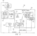
- FIG 3 shows an alternative embodiment in which the WLAN station 104 containing the WLAN card under test 106 is mounted on a motorized turntable 160.
- the turntable 160 is controlled by computer 134 via a motor control signal 162 coupling the computer 134 to the turntable.
- the GUI on the computer 134 permits a user to specify the orientation of the turntable and thus orient to the antenna 108 associated with the card under test 106 to one or more positions. As such, the operator can examine the effects of antenna orientation on packet error rate for various antenna 108 orientations.
- the preferred embodiments of the invention as depicted in Figures 1 and 3 have test data packets transmitted by RF signal generator 132 and acknowledgment packets received by a separate piece of equipment, controller 114.
- the functions performed by RF signal generator 132 and controller 114 are combined together into a single piece of equipment.
- a single antenna may be used to send test data packets and receive acknowledgments packets.
- the preferred embodiment described above provides a method and system by which packet error rates of competing WLAN cards can be determined, for varying levels of noise if desired, and compared against one another. This information is useful for a variety of reasons such as determining how a manufacturer's WLAN card compares against competing cards on the market so that improvements can be made which benefit the public.
- a wireless access point is emulated so that the WLAN card being tested can be made to receive data packets and respond with acknowledgment packets in accordance with the wireless standard to which the card was designed.
- packet error rate based on acknowledgment packets, which are required by the applicable standard, knowledge of the card's software interface is not needed to determine which packets were received and which were lost.
Landscapes
- Engineering & Computer Science (AREA)
- Computer Networks & Wireless Communication (AREA)
- Signal Processing (AREA)
- Quality & Reliability (AREA)
- Mobile Radio Communication Systems (AREA)
- Small-Scale Networks (AREA)
Abstract
A test system (100) is disclosed in which the packet error rate of a wireless card can be determined without having knowledge of the software interface to the card. The wireless card under test (106) is placed inside an anechoic chamber (102). Test equipment emulates an access point and the card under test "associates" itself with the emulated access point. The test equipment includes an arbitrary waveform generator (130), RF signal generator (132), and a controller (114) which emulates an access point. The controller (114) commands the arbitrary waveform generator (130) and RF signal generator (132) to transmit a test data packet to the card under test (106). If the test data packet is correctly received by the test card (106), the card transmits back an acknowledgment packet. The controller (114) computes the packet error rate based on the number of lost packets relative to the total number of test data packets sent.
Description
- The present invention generally relates to a method of determining packet error rates of wireless stations. More particularly, the invention relates to a method of determining packet error rates in the face of varying degrees of noise for any manufacturer's wireless local area network ("WLAN") station.
- In a network of computers and/or related computing devices, data packets are transmitted across the network infrastructure from one node to another. A packet that is sent from a source node to a destination node is not always received by the destination node accurately. One or more bits may have flipped state (i.e., a logic "1" may have turned into a logic "0", and vice versa). This problem is particularly significant for wireless networks (e.g., IEEE 802.11 networks). Communications across a wireless medium are particularly susceptible to noise generated by equipment external to the wireless network.
- By way of background information, wireless networks (e.g., 802.11 networks) include two or more wireless stations capable of wirelessly communicating with one another. A typical architecture of such a wireless network includes one or more access points ("APs") each of which is associated with one or more wireless stations. A wireless station, that is not an AP, may comprise a portable computer that includes a wireless local area network ("LAN") card. The wireless LAN card may be provided by any one of a variety of manufacturers and includes one or more antennas and other electronics that control the operation of the wireless capability of the station.
- Most wireless networks include the ability to detect packet transmission errors and correct the error. For example, in an 802.11 network for each data packet transmitted to a destination station, the destination station transmits an acknowledgment packet back to the source station. The acknowledgment packet lets the source station know that the original data packet was correctly received by the destination station. If an acknowledgment packet is not received by the source station with in a predetermined period of time, the source station determines that an error occurred preventing the packet from being correctly received by the destination station. The source station then resends the original data packet with the expectation that the retransmitted data packet will be correctly received by the destination station. Because packet errors are often dealt with by retransmitting the packet, packet errors slow down the operation of the network and thus are highly undesirable.
- For a variety of reasons, it is desirable to know the packet error rate ("PER") for a wireless station. For purposes of this disclosure, the PER is defined as the percentage of packets sent to a station that are not correctly received. For example, if out of 100 packets, 98 are correctly received and 2 are not, the PER is 2%. Each manufacturer of wireless cards generally knows the PER of its own wireless cards, but may not know the PER of its competitors' wireless cards-the PER may be a parameter that a manufacturer does not make widely known. Even if a manufacturer did reveal its PER to the public, the PER is generally a function of the amount of noise present in the environment in which the wireless station is operating. That is, a higher level of noise generally causes more packets to be lost due to errors. Consequently, the PER of a wireless station generally increases with increasing levels of noise. As such, it would be desirable to compare PERs of various wireless cards as a function of noise level.
- Thus, it is generally desirable to compare the PER associated with one manufacturer's wireless card with the wireless card of another manufacturer, and to do so with varying levels of noise. With one's own wireless card, known registers and the like can be read to determine which packets were correctly received and which were not. With the wireless card of another manufacturer, it may not be known how to interact with the card's logic and/or software interface to access such information. Thus, a problem exists as to how determine the packet error rate of a wireless card in which the electronics contained thereon are proprietary thereby precluding easy access to registers and memory associated with the card.
- The problems noted above are solved in large part by a test configuration in which the packet error rate of a wireless card can be determined without having knowledge of the software interface to the card. In accordance with the preferred embodiment, the wireless card under test is placed inside an anechoic chamber. Test equipment, some of which may also be inside the chamber emulates an access point and the card under test "associates" itself with the emulated access point. At this point, the test card believes it is communicating with a conventional access point. The test equipment preferably includes an arbitrary waveform generator, RF signal generator, a computer through which an operator controls the system, and a controller which emulates an access point. The controller commands the arbitrary waveform generator and RF signal generator to transmit a test data packet to the card under test. If the packet is correctly received by the test card, the card transmits back an acknowledgment packet in accordance with the wireless standard to which it was designed (e.g., IEEE 802.11). The controller determines which test data packets are received by the test card and which are lost by "listening" for the acknowledgment packets. An absence of an acknowledgement packet indicates a lost test data packet. The controller then can compute the packet error rate by dividing the number of lost packets by the total number of test data packets sent (and multiplying by 100 to convert to a percentage value if desired). Preferably, the RF signal generator introduces a desired amount of noise into the test data packet. This permits the operator to determine the test card's packet error rate based on varying levels of noise.
- A preferred embodiment of determining the packet error rate of a wireless LAN card comprises (a) emulating an access point; (b) transmitting a data packet; (c) determining whether an acknowledgment packet has been received; (d) if an acknowledgment packet is not received, determining that the data packet has been lost; (e) if an acknowledgment packet is received, determining that the data packet has not been lost; (f) repeating (b)-(e) a predetermined number of times; and (g) computing a packet error rate based on the number of data packets determined to be lost relative to the number of data packets transmitted in (b).
- The preferred embodiments described herein permit the packet error rates of a variety of wireless cards to be determined and then compared against one another. This information is useful to wireless card manufacturers in their continued attempts to improve wireless technology.
- For a detailed description of the preferred embodiments of the invention, reference will now be made to the accompanying drawings in which:
- Figure 1 shows a preferred embodiment of a configuration in which a WLAN card can be tested to determine its packet error for varying levels of noise without having knowledge of the card's architecture and software interface;
- Figure 2 shows a plot comparing the packet error rates of two WLAN cards determined using the configuration shown in Figure 1; and
- Figure 3 shows an alternative in which a WLAN station containing the WLAN card under test is mounted on an electronically controllable turntable.
- Certain terms are used throughout the following description and claims to refer to particular system components. As one skilled in the art will appreciate, wireless device and equipment companies may refer to a component by different names. This document does not intend to distinguish between components that differ in name but not function. In the following discussion and in the claims, the terms "including" and "comprising" are used in an open-ended fashion, and thus should be interpreted to mean "including, but not limited to...". Also, the term "couple" or "couples" is intended to mean either an indirect or direct electrical connection. Thus, if a first device couples to a second device, that connection may be through a direct electrical connection, or through an indirect electrical connection via other devices and connections.
- Referring now to Figure 1, a
system 100 is shown in accordance with the preferred embodiment of the invention. As shown,system 100 includes ananechoic chamber 102 in which a WLAN card undertest 106 is placed for testing to determine the card's packet error rate in the face of varying levels of noise. Anechoic chambers are well known in the art as rooms which are lined with a material that absorbs radio waves over a range of frequencies. Externally produced radio frequency ("RF") energy thus is not permitted to penetrate the chamber to reach the WLAN card undertest 106 and other equipment contained therein. Further still, any RF energy generated by the equipment inside thechamber 102 radiates outward and is absorbed by the material lining the inside walls of the chamber and thus is not reflected thereby minimizing or preventing multipath radiation effects. - The WLAN card under
test 106 includes or is coupled to anantenna 108 as is well known. The WLAN card preferably is included in aWLAN station 104 that may comprise a portable computer or other suitable host device. TheWLAN station 104 preferably includes an interface to theEthernet 124 or other suitable communication link. - A
controller 114 is also located inside theanechoic chamber 102.Controller 114 includes a knownWLAN card 116 andantenna 118 for communicating with the WLAN card undertest 106 via awireless communication link 120. Thecontroller 114 preferably comprises a computer such as a notebook computer that also has an Ethernet interface. - The preferred embodiment of
system 100 also includes anarbitrary waveform generator 130, anRF signal generator 132 and a control station 134 (preferably a computer) which provides a graphical user interface ("GUI") by which an operator can control the testing of the WLAN card undertest 106. Thearbitrary waveform generator 130 preferably comprises a Tekronix AWG420/520 generator, or other suitable device. The arbitrary waveform generator converts stored digital I/Q samples to an analog signal which it then provides toRF signal generator 132. The analog signal produced by thearbitrary waveform generator 130 is a "baseband" signal. The baseband signal comprises a data packet which will be sent to the WLAN card undertest 106. The composition of the data packet is generally compliant with the wireless standard to which thetest card 106 comports. The data packet preferably contains header information as would be well known and a data payload. The data payload may be a random number sequence or other suitable value. - The
RF signal generator 132 converts the baseband signal from thearbitrary waveform generator 130 to an RF signal. If the WLAN card undertest 106 comprises an IEEE 802.11b-compliant card which operates in the Industry, Scientific and Medical ("ISM") band, theRF signal generator 132 is adjusted to convert the baseband signal from thearbitrary waveform generator 130 to the 2400 MHz ISM frequency band. Thearbitrary waveform generator 130, which may be a Tekronix AWG420/520 generator, preferably also includes the ability to introduce, vianoise control 133, a controlled amount of noise to the baseband data signal.Noise control 133 permits the amplitude of "white" noise to be controlled to a known level. Thus, the output signal from theRF signal generator 132 comprises a known test data packet to which a known amount of noise has been mixed. This data packet can then be transmitted to the WLAN card under test viaantenna 140 included inside theanechoic chamber 102 and connected toRF signal generator 132. - The
arbitrary waveform generator 130 andRF signal generator 132 may have well known GPIB interfaces and thus a GPIB-to-Ethernet bridge 138 is included to couple the waveform andRF signal generators computer 134 permits an operator the ability control and check the status and results of the system via a GUI implemented on thecomputer 134. Thecomputer 134 may be any suitable type of computer that has an Ethernet interface. - In general, each WLAN station and access point in a conventional WLAN has a unique address referred to as a "MAC address" to permit efficient communications in the WLAN. Referring still to Figure 1, the
controller 114 is assigned a MAC address and preferably emulates a WLAN access point. An operator initiates the interaction between the test system and the WLAN card undertest 106 by supplying the GUI with initialization parameters such as the MAC address of the test card 106 (which typically is printed on the card itself by the manufacturer), multipath conditions, packet size, number of test data packets to be transmitted, data rate, etc. Thecomputer 134 then configures the hardware with the information necessary to carry out communications with thetest card 106. Thecontroller 114 preferably generates a "beacon frame" template and sends this frame to the controller'sWLAN card 116 and configures other parameters of theWLAN card 116 such as data rate as would be appreciated by those of ordinary skill in the art. The operator also configures thetest card 106 for an "infrastructure" mode of operation in which the test card attempts to associate itself with an access point and communicates to a wireless network via the associated access point. The operator also specifies the service set identifier ("SSID") in accordance with known IEEE 802.11 techniques. - At this point the WLAN card under
test 106, as it is designed to do, begins transmitting "probe request" frames in an attempt to find a compatible access point. A probe request is a frame which contains the SSID of thetest card 106 and supported data rates. Upon receiving a probe request, thecontroller 114 responds by sending a probe response back to thetest card 106 to indicate the presence of the emulated access point. The controller'sWLAN card 116 and thetest card 106 then begin an "association" process. There are a variety of association techniques known to those of ordinary skill in the art. Once the WLAN card undertest 106 associates itself with the controller'sWLAN card 116, thecontroller 114 then can act as an access point. That is, the WLAN card undertest 106 believes thecontroller 114 is a legitimate access point. - At this point, the
controller 114 enters a loop under software control in which, via theEthernet 124, thecontroller 114 instructs theRF signal generator 132 to send a data packet to the WLAN card undertest 106 viawireless link 142. In accordance with the applicable standard to which thetest card 106 complies (e.g., IEEE 802.11), the test card receives the data packet and sends out an acknowledgment packet indicating the correct receipt of the data packet. In accordance with the preferred embodiment, the controller'sWLAN card 116 receives the acknowledgments ("ACKs") from the test card. Accordingly, thecontroller 114 knows when the data packet is sent and knows that the WLAN card undertest 106 has correctly received the data packet when the acknowledgment packet is received. If an acknowledgment packet is not received within a prescribed and/or programmable period of time (preferably dictated by the applicable wireless standard and specified via the GUI on computer 134), thecontroller 114 determines that the packet has been lost. Once thecontroller 114 determines the fate of the data packet (received or lost), thecontroller 114requests equipment - The
controller 114 repeats this process a predetermined or programmable number of times. In so doing, thecontroller 114 keeps track of the total number of test packets sent to the card undertest 106 and, of those packets, which packets were correctly received and which were lost. Thecontroller 114 thus can determine the packet error rate ("PER") for the test card by dividing the number of lost packets by the total number of packets and multiplying that result by 100 to convert to a "percentage" value (e.g., 2%). - As explained above, the
RF signal generator 132 permits the operator the ability to introduce a desired level of noise into the test data packet signal. Accordingly, the above process can be performed for a desired noise level and then repeated one or more times for other noise levels. Figure 2 shows a plot of packet error rate versus noise level. The exemplary plot of Figure 2 shows twocurves test 106. Each curve comprises a plurality of PER values each computed in accordance with the procedure described above for a certain noise level. As can be seen and would be expected, the packet error rates increase with increasing levels of noise. The PER versusnoise curve 152 shows that the PER for the card associated with that curve has a higher PER compared to the card associated withcurve 150. For example, at noise level Nx the PER oncurve 152 is higher than the corresponding point oncurve 150. - Figure 3 shows an alternative embodiment in which the
WLAN station 104 containing the WLAN card undertest 106 is mounted on amotorized turntable 160. Theturntable 160 is controlled bycomputer 134 via amotor control signal 162 coupling thecomputer 134 to the turntable. The GUI on thecomputer 134 permits a user to specify the orientation of the turntable and thus orient to theantenna 108 associated with the card undertest 106 to one or more positions. As such, the operator can examine the effects of antenna orientation on packet error rate forvarious antenna 108 orientations. - The preferred embodiments of the invention as depicted in Figures 1 and 3 have test data packets transmitted by
RF signal generator 132 and acknowledgment packets received by a separate piece of equipment,controller 114. In accordance with another embodiment of the invention, the functions performed byRF signal generator 132 andcontroller 114 are combined together into a single piece of equipment. As such, a single antenna may be used to send test data packets and receive acknowledgments packets. - The preferred embodiment described above provides a method and system by which packet error rates of competing WLAN cards can be determined, for varying levels of noise if desired, and compared against one another. This information is useful for a variety of reasons such as determining how a manufacturer's WLAN card compares against competing cards on the market so that improvements can be made which benefit the public. A wireless access point is emulated so that the WLAN card being tested can be made to receive data packets and respond with acknowledgment packets in accordance with the wireless standard to which the card was designed. By determining packet error rate based on acknowledgment packets, which are required by the applicable standard, knowledge of the card's software interface is not needed to determine which packets were received and which were lost.
- The above discussion is meant to be illustrative of the principles and various embodiments of the present invention. Numerous variations and modifications will become apparent to those skilled in the art once the above disclosure is fully appreciated. It is intended that the following claims be interpreted to embrace all such variations and modifications.
Claims (10)
- A method of determining the packet error rate of a wireless LAN card, comprising:(a) emulating an access point;(b) transmitting a data packet to the wireless LAN card;(c) determining whether an acknowledgment packet has been received from said wireless LAN card;(d) if an acknowledgment packet is not received, determining that the data packet has been lost;(e) if an acknowledgment packet is received, determining that the data packet has not been lost;(f) repeating (b)-(e) a predetermined number of times; and(g) computing a packet error rate based on the number of data packets determined to be lost relative to the number of data packets transmitted in (b).
- The method of claim 1 wherein (b) includes transmitting noise having a predetermined level with said data packet; and further including repeating (b)-(g) for different levels of said predetermined level of noise.
- The method of either of claim 1 or 2 wherein (a) includes receiving a probe request and transmitting a probe response that includes a MAC address.
- The method of any of claims 1 to 3 further including associating the computed packet error rate or rates with the wireless LAN card for which the packet error rate is or rates are computed in (g).
- The method of any of claims 1 to 4 wherein (b) is performed inside an anechoic chamber.
- The method of any of claims 1 to 5 further including repeating (b)-(g) for different orientations of an antenna associated with said wireless card.
- A system that determines a packet error rate for a first wireless LAN card, comprising:a controller that includes a second wireless LAN card and that wirelessly communicates with said first wireless LAN card;a test data packet generator having an antenna through which test data packets are transmitted to said first wireless LAN card;a computer coupled to said controller, first wireless LAN card and test data packet generator through which an operator can control the system;wherein said controller emulates an access point, said test data packet generator sends test data packets to said first wireless LAN card, and said controller determines whether acknowledgment packets are received from said first wireless LAN card and computes a packet error rate.
- The system of claim 7 wherein said test data packet generator comprises an arbitrary waveform generator coupled to an RF signal generator.
- The system of claim 8 wherein said arbitrary signal generator introduces a controlled level of noise to said test data packet; and wherein said controller computes packet error rates for said first wireless LAN card for different ones of said level of noise.
- The system of any of claims 7 to 9 wherein said controller determines a test data packet is lost when no acknowledgment packet is received within a prescribed period of time and computes said packet error rate by dividing the number of lost test data packets by the total number of test data packets transmitted.
Applications Claiming Priority (2)
| Application Number | Priority Date | Filing Date | Title |
|---|---|---|---|
| US10/277,856 US20040076138A1 (en) | 2002-10-22 | 2002-10-22 | Method for determining packet error rate of wireless lan stations |
| US277856 | 2002-10-22 |
Publications (1)
| Publication Number | Publication Date |
|---|---|
| EP1414179A1 true EP1414179A1 (en) | 2004-04-28 |
Family
ID=32069317
Family Applications (1)
| Application Number | Title | Priority Date | Filing Date |
|---|---|---|---|
| EP20030103912 Withdrawn EP1414179A1 (en) | 2002-10-22 | 2003-10-22 | A method for determining packet error rate of wireless LAN stations |
Country Status (2)
| Country | Link |
|---|---|
| US (1) | US20040076138A1 (en) |
| EP (1) | EP1414179A1 (en) |
Cited By (5)
| Publication number | Priority date | Publication date | Assignee | Title |
|---|---|---|---|---|
| EP1659743A1 (en) * | 2004-11-19 | 2006-05-24 | Research In Motion Limited | Method and system for identifying degradation of a media service by determining a packet loss rate |
| WO2006102840A1 (en) * | 2005-03-30 | 2006-10-05 | Huawei Technologies Co., Ltd. | A method for monitoring the packet loss rate |
| DE102007038337A1 (en) * | 2007-08-14 | 2009-02-19 | Rohde & Schwarz Gmbh & Co. Kg | Method for testing devices for a mobile radio system, signal generator, device for a mobile radio system and measuring system |
| US7773517B2 (en) | 2004-11-19 | 2010-08-10 | Research In Motion Limited | Method and system for identifying degradation of a media service |
| EP2426979A4 (en) * | 2009-04-30 | 2014-12-10 | Fujitsu Ltd | WIRELESS COMMUNICATION DEVICE AND WIRELESS COMMUNICATION METHOD |
Families Citing this family (14)
| Publication number | Priority date | Publication date | Assignee | Title |
|---|---|---|---|---|
| US20050101257A1 (en) * | 2002-05-30 | 2005-05-12 | 6Lan | Wireless local area network test device |
| US8068441B1 (en) * | 2003-06-05 | 2011-11-29 | Mcafee, Inc. | Automated discovery of access points in wireless computer networks |
| US7747734B2 (en) * | 2006-03-29 | 2010-06-29 | International Business Machines Corporation | Apparatus, system, and method for error assessment over a communication link |
| US7865147B2 (en) * | 2006-04-14 | 2011-01-04 | Litepoint Corporation | System for testing an embedded wireless transceiver |
| US8676188B2 (en) * | 2006-04-14 | 2014-03-18 | Litepoint Corporation | Apparatus, system and method for calibrating and verifying a wireless communication device |
| US8131223B2 (en) * | 2006-04-14 | 2012-03-06 | Litepoint Corporation | System for testing an embedded wireless transceiver |
| GB0608471D0 (en) * | 2006-04-28 | 2006-06-07 | Agilent Technologies Inc | A method and apparatus for measuring the error rate of a communication device |
| FR2903257A1 (en) * | 2006-06-30 | 2008-01-04 | Thomson Licensing Sas | COMMUNICATION METHOD ADAPTED FOR TRANSMITTING DATA PACKETS |
| EP2642783A1 (en) * | 2012-03-19 | 2013-09-25 | Thomson Licensing | Method for testing a wireless communications network including a station and an access point |
| US9559806B2 (en) * | 2012-12-04 | 2017-01-31 | Dali Systems Co. Ltd. | Power amplifier protection using a cyclic redundancy check on the digital transport of data |
| CN105323814B (en) * | 2014-07-23 | 2019-04-23 | 中兴通讯股份有限公司 | Optimal processing method and device for terminal service migration |
| US9743297B1 (en) * | 2016-05-27 | 2017-08-22 | Ixia | Methods, systems, and computer readable media for testing wireless devices in wireless environments |
| US11838776B2 (en) * | 2020-10-23 | 2023-12-05 | Litepoint Corporation | System and method for testing a data packet signal transceiver |
| TWI847629B (en) * | 2023-03-25 | 2024-07-01 | 瑞昱半導體股份有限公司 | Wireless transceiver device and wireless transmission mode switching method |
Citations (3)
| Publication number | Priority date | Publication date | Assignee | Title |
|---|---|---|---|---|
| EP0637150A1 (en) * | 1993-07-26 | 1995-02-01 | AT&T Corp. | A 1200 bit per second fallback method for use in mobile radio |
| EP0872979A2 (en) * | 1997-04-17 | 1998-10-21 | Advanced Micro Devices, Inc. | System and method for monitoring performance of wireless lan and dynamically adjusting its operating parameters |
| US20010052091A1 (en) * | 2000-06-07 | 2001-12-13 | Agilent Technologies, Inc. | Block error rate measurements |
Family Cites Families (5)
| Publication number | Priority date | Publication date | Assignee | Title |
|---|---|---|---|---|
| JP2661551B2 (en) * | 1994-07-13 | 1997-10-08 | 日本電気株式会社 | Wireless LAN system |
| US5805667A (en) * | 1997-01-02 | 1998-09-08 | Lucent Technologies Inc. | Apparatus for range-testing cordless communication devices and method of operation thereof |
| US6989797B2 (en) * | 1998-09-21 | 2006-01-24 | Ipr Licensing, Inc. | Adaptive antenna for use in wireless communication systems |
| US6236362B1 (en) * | 1999-04-20 | 2001-05-22 | Harris Corporation | Mitigation of antenna test range impairments caused by presence of undesirable emitters |
| US6694134B1 (en) * | 2002-03-18 | 2004-02-17 | Interwave Communications International, Ltd. | Terminal device emulator |
-
2002
- 2002-10-22 US US10/277,856 patent/US20040076138A1/en not_active Abandoned
-
2003
- 2003-10-22 EP EP20030103912 patent/EP1414179A1/en not_active Withdrawn
Patent Citations (3)
| Publication number | Priority date | Publication date | Assignee | Title |
|---|---|---|---|---|
| EP0637150A1 (en) * | 1993-07-26 | 1995-02-01 | AT&T Corp. | A 1200 bit per second fallback method for use in mobile radio |
| EP0872979A2 (en) * | 1997-04-17 | 1998-10-21 | Advanced Micro Devices, Inc. | System and method for monitoring performance of wireless lan and dynamically adjusting its operating parameters |
| US20010052091A1 (en) * | 2000-06-07 | 2001-12-13 | Agilent Technologies, Inc. | Block error rate measurements |
Cited By (9)
| Publication number | Priority date | Publication date | Assignee | Title |
|---|---|---|---|---|
| EP1659743A1 (en) * | 2004-11-19 | 2006-05-24 | Research In Motion Limited | Method and system for identifying degradation of a media service by determining a packet loss rate |
| US7773517B2 (en) | 2004-11-19 | 2010-08-10 | Research In Motion Limited | Method and system for identifying degradation of a media service |
| US7986626B2 (en) | 2004-11-19 | 2011-07-26 | Research In Motion Limited | Method and system for identifying degradation of a media service |
| US8254283B2 (en) | 2004-11-19 | 2012-08-28 | Research In Motion Limited | Method and system for identifying degradation of a media service |
| US8687517B2 (en) | 2004-11-19 | 2014-04-01 | Blackberry Limited | Method and system for identifying degradation of a media service |
| WO2006102840A1 (en) * | 2005-03-30 | 2006-10-05 | Huawei Technologies Co., Ltd. | A method for monitoring the packet loss rate |
| DE102007038337A1 (en) * | 2007-08-14 | 2009-02-19 | Rohde & Schwarz Gmbh & Co. Kg | Method for testing devices for a mobile radio system, signal generator, device for a mobile radio system and measuring system |
| US8666392B2 (en) | 2007-08-14 | 2014-03-04 | Rohde & Schwarz Gmbh & Co. Kg | Method for testing appliances for a mobile-radio system, signal generator, appliance for a mobile-radio system, and a measurement system |
| EP2426979A4 (en) * | 2009-04-30 | 2014-12-10 | Fujitsu Ltd | WIRELESS COMMUNICATION DEVICE AND WIRELESS COMMUNICATION METHOD |
Also Published As
| Publication number | Publication date |
|---|---|
| US20040076138A1 (en) | 2004-04-22 |
Similar Documents
| Publication | Publication Date | Title |
|---|---|---|
| US20040076138A1 (en) | Method for determining packet error rate of wireless lan stations | |
| Abedi et al. | Witag: Seamless wifi backscatter communication | |
| US7224704B2 (en) | Wireless network scheduling data frames including physical layer configuration | |
| US6671495B1 (en) | Method for transmitting measurement data in a wireless communication system and a wireless communication system | |
| US20030072280A1 (en) | Method and system for variable rate acknowledgement for wireless communication protocols | |
| US8693351B2 (en) | System and method for deterministic testing of packet error rate in electronic devices | |
| CN100477557C (en) | wireless communication system | |
| US7991392B2 (en) | Communication system, information processing apparatus, and communication control method | |
| US11737152B2 (en) | Wireless communication method using TXOP and wireless communication terminal using same | |
| US7978675B1 (en) | Extension mode for wireless LANs complying with short interframe space requirement | |
| WO2002028024A2 (en) | Architecture for a wireless local area network node | |
| EP1096729A1 (en) | Rate adaptive payload transmission for local area networks | |
| EP1784952A1 (en) | Method and system for acknowledging the receipt of a transmitted data stream in a wireless personal area network | |
| JP7598398B2 (en) | COMMUNICATION DEVICE, CONTROL METHOD FOR COMMUNICATION DEVICE, AND PROGRAM | |
| WO2022133927A1 (en) | Systems and methods for initializing harq-ack procedure by a specific dci for beam indication | |
| US20070254643A1 (en) | Method and apparatus for measuring the error rate of a communication device | |
| JP6483635B2 (en) | Wireless communication apparatus and wireless communication method | |
| WO2022079992A1 (en) | Terminal, communication device, and communication method | |
| CN110731069A (en) | Method for Controlling Wireless Device Under Test Using Unlinked Test Resources | |
| CN110392390A (en) | WLAN transmitting power setting method, setting device and wireless access point | |
| US20150358839A1 (en) | Method and system for testing a radio frequency data packet signal transceiver at a low network media layer | |
| BRPI0014097B1 (en) | Method and system for timing diversity weighting factor changes in a cellular radio system | |
| Endovitskiy et al. | Experimental study of capture effect in smartphones and Wi-Fi access points | |
| CN100459550C (en) | Communication area reserving method | |
| US20260005800A1 (en) | Incorporating a soliciting frame signature into a message integrity check (mic) of a response frame |
Legal Events
| Date | Code | Title | Description |
|---|---|---|---|
| PUAI | Public reference made under article 153(3) epc to a published international application that has entered the european phase |
Free format text: ORIGINAL CODE: 0009012 |
|
| AK | Designated contracting states |
Kind code of ref document: A1 Designated state(s): AT BE BG CH CY CZ DE DK EE ES FI FR GB GR HU IE IT LI LU MC NL PT RO SE SI SK TR |
|
| AX | Request for extension of the european patent |
Extension state: AL LT LV MK |
|
| 17P | Request for examination filed |
Effective date: 20041028 |
|
| AKX | Designation fees paid |
Designated state(s): DE FR GB |
|
| 17Q | First examination report despatched |
Effective date: 20050701 |
|
| STAA | Information on the status of an ep patent application or granted ep patent |
Free format text: STATUS: THE APPLICATION IS DEEMED TO BE WITHDRAWN |
|
| 18D | Application deemed to be withdrawn |
Effective date: 20051112 |