EP1414136A1 - Permanent magnet rotor and corresponding method of manufacture - Google Patents
Permanent magnet rotor and corresponding method of manufacture Download PDFInfo
- Publication number
- EP1414136A1 EP1414136A1 EP20030021870 EP03021870A EP1414136A1 EP 1414136 A1 EP1414136 A1 EP 1414136A1 EP 20030021870 EP20030021870 EP 20030021870 EP 03021870 A EP03021870 A EP 03021870A EP 1414136 A1 EP1414136 A1 EP 1414136A1
- Authority
- EP
- European Patent Office
- Prior art keywords
- drum
- permanent magnet
- rotor
- magnet rotor
- electric machine
- Prior art date
- Legal status (The legal status is an assumption and is not a legal conclusion. Google has not performed a legal analysis and makes no representation as to the accuracy of the status listed.)
- Granted
Links
- 238000004519 manufacturing process Methods 0.000 title claims description 8
- 238000000034 method Methods 0.000 title description 2
- 238000010438 heat treatment Methods 0.000 claims abstract description 19
- 239000000463 material Substances 0.000 claims description 11
- 239000000696 magnetic material Substances 0.000 claims description 7
- 238000001816 cooling Methods 0.000 description 5
- 230000002093 peripheral effect Effects 0.000 description 5
- 238000002485 combustion reaction Methods 0.000 description 3
- KSOKAHYVTMZFBJ-UHFFFAOYSA-N iron;methane Chemical compound C.[Fe].[Fe].[Fe] KSOKAHYVTMZFBJ-UHFFFAOYSA-N 0.000 description 3
- 229910000734 martensite Inorganic materials 0.000 description 3
- 229910000859 α-Fe Inorganic materials 0.000 description 3
- 229910000831 Steel Inorganic materials 0.000 description 2
- 229910001567 cementite Inorganic materials 0.000 description 2
- 238000010276 construction Methods 0.000 description 2
- 230000012447 hatching Effects 0.000 description 2
- 238000012986 modification Methods 0.000 description 2
- 230000004048 modification Effects 0.000 description 2
- 239000010959 steel Substances 0.000 description 2
- 229910001566 austenite Inorganic materials 0.000 description 1
- 229910000963 austenitic stainless steel Inorganic materials 0.000 description 1
- 230000008859 change Effects 0.000 description 1
- 238000010894 electron beam technology Methods 0.000 description 1
- 230000001678 irradiating effect Effects 0.000 description 1
- 230000000717 retained effect Effects 0.000 description 1
- 230000009466 transformation Effects 0.000 description 1
Images


Classifications
-
- H—ELECTRICITY
- H02—GENERATION; CONVERSION OR DISTRIBUTION OF ELECTRIC POWER
- H02K—DYNAMO-ELECTRIC MACHINES
- H02K1/00—Details of the magnetic circuit
- H02K1/06—Details of the magnetic circuit characterised by the shape, form or construction
- H02K1/22—Rotating parts of the magnetic circuit
- H02K1/27—Rotor cores with permanent magnets
- H02K1/2706—Inner rotors
- H02K1/272—Inner rotors the magnetisation axis of the magnets being perpendicular to the rotor axis
- H02K1/274—Inner rotors the magnetisation axis of the magnets being perpendicular to the rotor axis the rotor consisting of two or more circumferentially positioned magnets
- H02K1/2753—Inner rotors the magnetisation axis of the magnets being perpendicular to the rotor axis the rotor consisting of two or more circumferentially positioned magnets the rotor consisting of magnets or groups of magnets arranged with alternating polarity
- H02K1/278—Surface mounted magnets; Inset magnets
-
- H—ELECTRICITY
- H02—GENERATION; CONVERSION OR DISTRIBUTION OF ELECTRIC POWER
- H02K—DYNAMO-ELECTRIC MACHINES
- H02K1/00—Details of the magnetic circuit
- H02K1/06—Details of the magnetic circuit characterised by the shape, form or construction
- H02K1/22—Rotating parts of the magnetic circuit
- H02K1/28—Means for mounting or fastening rotating magnetic parts on to, or to, the rotor structures
- H02K1/30—Means for mounting or fastening rotating magnetic parts on to, or to, the rotor structures using intermediate parts, e.g. spiders
Definitions
- the invention relates to a rotating-type electric machine (hereinafter referred to as "rotary electric machine") having a rotor and a stator which encircles the rotor, such as a motor, generator, or motor/generator. More specifically, the invention relates to a permanent magnet rotor of that rotary electric machine and manufacturing method of that permanent magnet rotor.
- JP-A-10-42498 proposes to achieve a desired magnetic characteristic by irradiating a laser or electron beam at a predetermined region along an outer edge of a rectangular border of the permanent magnets to locally heat up that region and demagnetize it.
- JP-A-4-183238 proposes constructing a sturdy housing for the permanent magnets by fitting both end portions of an outer cylinder which wraps around the permanent magnets in a flange-shaped peripheral edge portion of a disc-shaped end plate.
- JP-A-2000-145469 proposes improving the efficiency of assembling a rotary electric machine incorporated into a supercharger by magnetizing the rotor when it is mounted on a rotating shaft and installing the main rotating parts as a single unit into a center housing.
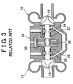
- FIG. 3 is a sectional view illustrating one example of a supercharger incorporating this kind of rotary electric machine.
- a supercharger rotor in which a turbine rotor 16 of a turbine portion 10, a compressor impeller 18 of a compressor portion 12, and a rotor 20 of a rotary electric machine portion 14 are all integrally coupled together, is rotatably supported by a bearing 24 at a shaft portion 22 between the turbine rotor 16 and the rotor 20, as well as by a bearing 28 at a shaft portion 26 between the compressor impeller 18 and the rotor 20.
- the rotary electric machine portion 14 has a stator 30 which is provided around the rotor 20. In FIG. 3, only the core portion of the stator 30 is shown. The coil is omitted from the drawing for the sake of simplicity.
- FIG. 4 is a sectional view showing an enlargement of a portion of the rotor 20.
- a concentric cylindrical body divided into a plurality of individual circular discs is generally provided along the periphery of the shaft portion 23 between the shaft portions 22 and 26.
- Each of the permanent magnets 32 is magnetized such that the side near the center axis of the rotor 20 and the side away from the center axis have opposing polarities.
- the outer surface of half of the periphery of the rotor is an N pole and the outer surface of the remaining half of the periphery of the rotor is an S pole.
- a layer 34 made of magnetic material is provided on the inside in the radial direction of the permanent magnets 32.
- a sleeve 36 formed of magnetic material integrally surrounds the series of permanent magnets 32 so as to hold them in place against centrifugal force that acts on them as the rotor 20 rotates.
- a pair of rings 38 abut against both ends in the axial direction of the series of permanent magnets 32 to keep them in position in the axial direction.
- the rings 38 are fitted around the magnetic layer 34.
- the length in the axial direction of the magnetic layer 34 and the length in the axial direction of the permanent magnets 32 may also be made the same and the rings may be fitted directly on the shaft portion 22.
- the rings 38 are members which both serve to maintain the position of the permanent magnets 32 in the axial direction, and provide a portion which can be shaved off to reduce the mass at a suitable location in order to rotationally balance the rotor 20 around its axis.
- the rings 38 are therefore made of nonmagnetic material so that the shavings that have been shaved off will not be magnetically attracted to the magnetic parts.
- the rings 38 contact the magnetic layer 34 over a very small area (this is also the case when the rings 38 are fitted directly around the shaft portion 22). Therefore, when the rotor is rotated at high speeds well exceeding 100,000 rpm, such as does a rotor in a rotary electric machine in a supercharger of an internal combustion engine, the rings 38 expand radially due to the strong pull from the centrifugal force. Even if the rings 38 are fitted tightly around the magnetic layer 34 beforehand, there is no frictional force between the rings 38 and the magnetic layer 34 so the rings 38 slide in the direction of rotation and their relative rotational positions change with respect to the overall rotor.
- the rotor 20 which was rotationally balanced by shaving off a portion of the rings 38, may become unbalanced again.
- some sort of retaining means may be provided at a portion of the rings 38. Doing so, however, results in a concentration of stress at that location, which may lead to a loss of durability of the rings and the magnetic layer or the rotor shaft.
- the invention thus provides an improved permanent magnet rotor for a rotary electric machine.
- a first aspect of the invention relates to a permanent magnet rotor for a rotary electric machine.
- This permanent magnet rotor has a drum which supports permanent magnets.
- the drum is formed of an original body of nonmagnetic material, which, except for at least one shaft end portion thereof, has been magnetized by heat treatment.
- a second aspect of the invention relates to a permanent magnet rotor for a rotary electric machine.
- This permanent magnet rotor has a drum which supports permanent magnets.
- the original body of the drum is magnetic and at least one shaft end portion thereof is demagnetized by heat treatment.
- the "original body” refers to a body in a state in which, prior to a finished state in which the drum is nonmagnetic at at least one shaft end portion and magnetic at the other portions, the drum is either all nonmagnetic or all magnetic.
- This kind of permanent magnet rotor may also further include a sleeve that encircles the permanent magnets and holds them around the drum. This sleeve may also fit tightly around the shaft end portion of the drum at the shaft end portion.
- the permanent magnet rotor may also be a rotor for a rotary electric machine in a supercharger having a rotary electric machine.
- the permanent magnet rotor of the rotary electric machine has a drum which supports permanent magnets, the drum is formed of an original body of magnetic material, which, except for at least one shaft end portion thereof, has been demagnetized by heat treatment. Accordingly, the drum, which both serves to position the permanent magnets around the rotational axis of the rotor as well as provide a portion of which part of the material can be shaved off to achieve rotational balance of the rotor, can be of a construction in which the magnetic layer 34 and the rings 38 of the conventional permanent magnet rotor as illustrated in FIG. 4 are integrated.
- the portion corresponding to the rings 38 is a portion that continues from that integrated structure such that, even if strong centrifugal force acts on that part, the supporting structure of the permanent magnets is able to be reliably retained and the rotational balance, once achieved, is able to be stably maintained.
- the drum is formed of the magnetic layer 34 and the rings 38 integrated together in the conventional permanent magnet rotor illustrated in FIG. 4, but the drum itself need not be limited to this integrated structure. Making the drum itself an integrated structure is preferable in terms of strength, but for convenience in terms of assembly, the drum may also be divided into a plurality of individual sections which can then be assembled.
- the means which keeps the permanent magnets in a predetermined position in the radial, circumferential, and axial directions of the rotor is integrated with the structural body, i.e., the drum, which greatly improves the rotor structurally as well as in terms of strength and stability. Further, operating performance and durability of the rotor also greatly improve.
- a double cylinder structural body which combines, at the shaft end portion, an inner cylinder which wraps around the series of permanent magnets arranged cylindrically, and an outer cylinder.
- this structure of the rotor enables increased operability and durability of a supercharger when applied to a rotary electric machine of a supercharger for an internal combustion engine, which operates at high speeds well exceeding 100,000 rpm, and occasionally even 200,000 rpm.
- a third aspect of the invention relates to a manufacturing method of a permanent magnet rotor of a rotary electric machine, which includes the steps of magnetizing an original body, except for at least one shaft end portion thereof, of nonmagnetic material in a drum shape by heat treatment, and supporting permanent magnets on the heat-treated original body.
- a fourth aspect of the invention relates to a manufacturing method of a permanent magnet rotor, which includes the steps of demagnetizing at least one shaft end portion of an original body of magnetic material in a drum shape by heat treatment, and supporting permanent magnets on the heat-treated original body.
- the methods of the third and fourth aspects of the invention both enable manufacture of the permanent magnet rotors of the first and second aspects of the invention.
- FIG. 1 is a schematic view illustrating a rotor of a rotary electric machine according to a first exemplary embodiment of the invention for comparison with an example of a conventional rotor structure shown in FIG. 4.
- a shaft portion 23, a stator core 30, a permanent magnet 32, and a sleeve 36 which all correspond to portions shown in FIG. 4, are denoted by the same reference numerals as they are in FIG. 4.
- the portion corresponding to the combination of the magnetic layer 34 and the pair of rings 38 in the conventional example in FIG. 4 is made as a drum 100 from material which is initially nonmagnetic.
- both end portions 102 which are distinguished by hatching in the drawing
- the remaining portion 104 is then magnetized by heat treatment.
- a nonmagnetic portion of the drum 100 is shaved off to achieve rotational balance of the rotor.
- the permanent magnet 32 is supported by the outer periphery of the heat-treated drum 100.
- the sleeve 36 in the illustrated exemplary embodiment is longer than the sleeve 36 in the conventional example shown in FIG. 4 by the length covering both end portions 102 of the drum 100.
- the sleeve 36 By having the sleeve 36 fit tightly around the outer peripheral surface of both end portions of the drum 100 as well as around the outer peripheral surface of the permanent magnet 32, the sleeve 36 holds the permanent magnet 32 to the drum 100 while achieving a sturdy double-cylinder joined structure of the drum 100 and the sleeve 36.
- the nonmagnetic material is able to be magnetized by heat treatment by, for example, heating a nonmagnetic austenitic stainless steel and then cooling it while controlling the cooling rate so that it transforms into any one of a magnetic ferrite, cementite, or martensite.
- a nonmagnetic austenitic stainless steel when the steel is gradually cooled from the austenitic state, layers of ferrite and cementite form alternately. As the cooling rate increases, the ferrite and cementite gradually combine at a fine level. Beyond a certain cooling rate, martensite forms.
- heat treatment may be performed such that a portion of the material to be heated is heated while a portion not to be heated is forcibly cooled.
- FIG. 2 is a schematic view illustrating a rotor of a rotary electric machine according to a second exemplary embodiment of the invention for comparison with the example of the conventional rotor structure shown in FIG. 4.
- the shaft portion 23, the stator core 30, the permanent magnet 32, and the sleeve 36, which all correspond to portions shown in FIG. 4, are denoted by the same reference numerals as they are in FIG. 4.
- the portion corresponding to the combination of the magnetic layer 34 and the pair of rings 38 in the conventional example in FIG. 4 is made as a drum 200 from material which is initially magnetic. Both end portions 202, which are distinguished by hatching in the drawing, are then demagnetized by heat treatment while the rest of the portion 204 remains magnetized.
- the permanent magnet 32 is supported on the outer periphery of the heat-treated drum 200, as shown in FIG. 2. Then, a nonmagnetic portion of the drum 200 is shaved off to achieve rotational balance of the rotor.
- the sleeve 36 be of a length that enables it to fit tightly around the outer peripheral surface of both end portions of the drum 200 as well as around the outer peripheral surface of the permanent magnet 32, the sleeve 36 holds the permanent magnet 32 to the drum 200 while achieving a sturdy double-cylinder joined structure of the drum 200 and the sleeve 36.
- the portion of the magnetic material is able to be demagnetized by heat treatment by, for example, intensively processing metastable austenite such that it undergoes martensitic transformation, and then heating only the portion to be demagnetized by high-frequency heating or the like.
- the length of the drum is longer in the axial direction than the length of the permanent magnet in the axial direction, and the drum has a groove in its periphery that is of a length in the axial direction that is equal to the length of the permanent magnet in the axial direction. More specifically, the outer diameter of both end portions of the drum are greater than the inner diameter of the cylindrical permanent magnet formed by the individual permanent magnets. The permanent magnets are housed in the groove such that they are held to the drum. Further, the drum, which is a single body, has a magnetic portion and a nonmagnetic portion.
- the rotor according to the first and second exemplary embodiments may also be used as a rotor of the rotary electric machine in a supercharger having a rotary electric machine.
- the drum be a single body, as is described in the first and second exemplary embodiments.
- the drum may also be divided into a plurality of individual sections which can then be assembled.
- at least one of the individual sections has a magnetic portion and a nonmagnetic portion.
Landscapes
- Engineering & Computer Science (AREA)
- Power Engineering (AREA)
- Permanent Field Magnets Of Synchronous Machinery (AREA)
- Supercharger (AREA)
Abstract
Description
- The invention relates to a rotating-type electric machine (hereinafter referred to as "rotary electric machine") having a rotor and a stator which encircles the rotor, such as a motor, generator, or motor/generator. More specifically, the invention relates to a permanent magnet rotor of that rotary electric machine and manufacturing method of that permanent magnet rotor.
- As a rotor for a rotary electric machine, a permanent magnet rotor in which permanent magnets are arranged in a circle around a shaft is already well known, and there are proposals for many improvements relating to that kind of rotor. For example, JP-A-10-42498 proposes to achieve a desired magnetic characteristic by irradiating a laser or electron beam at a predetermined region along an outer edge of a rectangular border of the permanent magnets to locally heat up that region and demagnetize it. JP-A-4-183238 proposes constructing a sturdy housing for the permanent magnets by fitting both end portions of an outer cylinder which wraps around the permanent magnets in a flange-shaped peripheral edge portion of a disc-shaped end plate. JP-A-2000-145469 proposes improving the efficiency of assembling a rotary electric machine incorporated into a supercharger by magnetizing the rotor when it is mounted on a rotating shaft and installing the main rotating parts as a single unit into a center housing.
- Because the permanent magnet rotor is of a lightweight construction, it is suitable for rotating at high speeds. Rotors used in rotary electric machines in superchargers for internal combustion engines, which operate at high speeds well exceeding 100,000 rpm are normally permanent magnet rotors. FIG. 3 is a sectional view illustrating one example of a supercharger incorporating this kind of rotary electric machine. A supercharger rotor, in which a
turbine rotor 16 of aturbine portion 10, acompressor impeller 18 of acompressor portion 12, and arotor 20 of a rotaryelectric machine portion 14 are all integrally coupled together, is rotatably supported by abearing 24 at ashaft portion 22 between theturbine rotor 16 and therotor 20, as well as by abearing 28 at ashaft portion 26 between thecompressor impeller 18 and therotor 20. The rotaryelectric machine portion 14 has astator 30 which is provided around therotor 20. In FIG. 3, only the core portion of thestator 30 is shown. The coil is omitted from the drawing for the sake of simplicity. - FIG. 4 is a sectional view showing an enlargement of a portion of the
rotor 20. In the drawing, a concentric cylindrical body divided into a plurality of individual circular discs is generally provided along the periphery of theshaft portion 23 between theshaft portions permanent magnets 32 is magnetized such that the side near the center axis of therotor 20 and the side away from the center axis have opposing polarities. When thepermanent magnets 32 are assembled, the outer surface of half of the periphery of the rotor is an N pole and the outer surface of the remaining half of the periphery of the rotor is an S pole. Alayer 34 made of magnetic material is provided on the inside in the radial direction of thepermanent magnets 32. Asleeve 36 formed of magnetic material integrally surrounds the series ofpermanent magnets 32 so as to hold them in place against centrifugal force that acts on them as therotor 20 rotates. - A pair of
rings 38 abut against both ends in the axial direction of the series ofpermanent magnets 32 to keep them in position in the axial direction. In the illustrated example, therings 38 are fitted around themagnetic layer 34. However, the length in the axial direction of themagnetic layer 34 and the length in the axial direction of thepermanent magnets 32 may also be made the same and the rings may be fitted directly on theshaft portion 22. Therings 38 are members which both serve to maintain the position of thepermanent magnets 32 in the axial direction, and provide a portion which can be shaved off to reduce the mass at a suitable location in order to rotationally balance therotor 20 around its axis. Therings 38 are therefore made of nonmagnetic material so that the shavings that have been shaved off will not be magnetically attracted to the magnetic parts. - According to the structure of the
conventional rotor 20 illustrated in FIG. 4, therings 38 contact themagnetic layer 34 over a very small area (this is also the case when therings 38 are fitted directly around the shaft portion 22). Therefore, when the rotor is rotated at high speeds well exceeding 100,000 rpm, such as does a rotor in a rotary electric machine in a supercharger of an internal combustion engine, therings 38 expand radially due to the strong pull from the centrifugal force. Even if therings 38 are fitted tightly around themagnetic layer 34 beforehand, there is no frictional force between therings 38 and themagnetic layer 34 so therings 38 slide in the direction of rotation and their relative rotational positions change with respect to the overall rotor. As a result, therotor 20, which was rotationally balanced by shaving off a portion of therings 38, may become unbalanced again. In order to prevent therings 38 from sliding, some sort of retaining means may be provided at a portion of therings 38. Doing so, however, results in a concentration of stress at that location, which may lead to a loss of durability of the rings and the magnetic layer or the rotor shaft. - In view of the foregoing problems, the invention thus provides an improved permanent magnet rotor for a rotary electric machine.
- A first aspect of the invention relates to a permanent magnet rotor for a rotary electric machine. This permanent magnet rotor has a drum which supports permanent magnets. The drum is formed of an original body of nonmagnetic material, which, except for at least one shaft end portion thereof, has been magnetized by heat treatment.
- A second aspect of the invention relates to a permanent magnet rotor for a rotary electric machine. This permanent magnet rotor has a drum which supports permanent magnets. The original body of the drum is magnetic and at least one shaft end portion thereof is demagnetized by heat treatment.
- The "original body" refers to a body in a state in which, prior to a finished state in which the drum is nonmagnetic at at least one shaft end portion and magnetic at the other portions, the drum is either all nonmagnetic or all magnetic.
- This kind of permanent magnet rotor may also further include a sleeve that encircles the permanent magnets and holds them around the drum. This sleeve may also fit tightly around the shaft end portion of the drum at the shaft end portion.
- The permanent magnet rotor may also be a rotor for a rotary electric machine in a supercharger having a rotary electric machine.
- As described above, the permanent magnet rotor of the rotary electric machine has a drum which supports permanent magnets, the drum is formed of an original body of magnetic material, which, except for at least one shaft end portion thereof, has been demagnetized by heat treatment. Accordingly, the drum, which both serves to position the permanent magnets around the rotational axis of the rotor as well as provide a portion of which part of the material can be shaved off to achieve rotational balance of the rotor, can be of a construction in which the
magnetic layer 34 and therings 38 of the conventional permanent magnet rotor as illustrated in FIG. 4 are integrated. Therefore, the portion corresponding to therings 38 is a portion that continues from that integrated structure such that, even if strong centrifugal force acts on that part, the supporting structure of the permanent magnets is able to be reliably retained and the rotational balance, once achieved, is able to be stably maintained. As described above, the drum is formed of themagnetic layer 34 and therings 38 integrated together in the conventional permanent magnet rotor illustrated in FIG. 4, but the drum itself need not be limited to this integrated structure. Making the drum itself an integrated structure is preferable in terms of strength, but for convenience in terms of assembly, the drum may also be divided into a plurality of individual sections which can then be assembled. - Also, the means which keeps the permanent magnets in a predetermined position in the radial, circumferential, and axial directions of the rotor is integrated with the structural body, i.e., the drum, which greatly improves the rotor structurally as well as in terms of strength and stability. Further, operating performance and durability of the rotor also greatly improve.
- Further, as described above, by having the sleeve, which encircles the permanent magnets on the drum so as to hold these permanent magnets around the drum, fit tightly around the shaft end portion of the drum, a double cylinder structural body is formed which combines, at the shaft end portion, an inner cylinder which wraps around the series of permanent magnets arranged cylindrically, and an outer cylinder. As a result, the structural stability and strength is further improved with respect to high-speed rotation of the rotor.
- Accordingly, this structure of the rotor enables increased operability and durability of a supercharger when applied to a rotary electric machine of a supercharger for an internal combustion engine, which operates at high speeds well exceeding 100,000 rpm, and occasionally even 200,000 rpm.
- A third aspect of the invention relates to a manufacturing method of a permanent magnet rotor of a rotary electric machine, which includes the steps of magnetizing an original body, except for at least one shaft end portion thereof, of nonmagnetic material in a drum shape by heat treatment, and supporting permanent magnets on the heat-treated original body.
- A fourth aspect of the invention relates to a manufacturing method of a permanent magnet rotor, which includes the steps of demagnetizing at least one shaft end portion of an original body of magnetic material in a drum shape by heat treatment, and supporting permanent magnets on the heat-treated original body.
- The methods of the third and fourth aspects of the invention both enable manufacture of the permanent magnet rotors of the first and second aspects of the invention.
- The foregoing and further objects, features and advantages of the invention will become apparent from the following description of preferred embodiments with reference to the accompanying drawings, wherein like numerals are used to represent like elements and wherein:
- FIG. 1 is a schematic view illustrating a rotor for a rotary electric machine according to a first exemplary embodiment of the invention;
- FIG. 2 is a schematic view illustrating a rotor for a rotary electric machine according to a second exemplary embodiment of the invention;
- FIG. 3 is a sectional view illustrating a conventional example of a supercharger incorporating a rotary electric machine; and
- FIG. 4 is a sectional view showing an enlargement of a portion of the rotor of the rotary electric machine shown in FIG. 3.
- FIG. 1 is a schematic view illustrating a rotor of a rotary electric machine according to a first exemplary embodiment of the invention for comparison with an example of a conventional rotor structure shown in FIG. 4. Referring to FIG. 1, a
shaft portion 23, astator core 30, apermanent magnet 32, and asleeve 36, which all correspond to portions shown in FIG. 4, are denoted by the same reference numerals as they are in FIG. 4. In this exemplary embodiment, the portion corresponding to the combination of themagnetic layer 34 and the pair ofrings 38 in the conventional example in FIG. 4 is made as adrum 100 from material which is initially nonmagnetic. With the exception of bothend portions 102, which are distinguished by hatching in the drawing, the remainingportion 104 is then magnetized by heat treatment. Then, a nonmagnetic portion of thedrum 100 is shaved off to achieve rotational balance of the rotor. Thepermanent magnet 32 is supported by the outer periphery of the heat-treateddrum 100. Thesleeve 36 in the illustrated exemplary embodiment is longer than thesleeve 36 in the conventional example shown in FIG. 4 by the length covering both endportions 102 of thedrum 100. By having thesleeve 36 fit tightly around the outer peripheral surface of both end portions of thedrum 100 as well as around the outer peripheral surface of thepermanent magnet 32, thesleeve 36 holds thepermanent magnet 32 to thedrum 100 while achieving a sturdy double-cylinder joined structure of thedrum 100 and thesleeve 36. - The nonmagnetic material is able to be magnetized by heat treatment by, for example, heating a nonmagnetic austenitic stainless steel and then cooling it while controlling the cooling rate so that it transforms into any one of a magnetic ferrite, cementite, or martensite. In this case, when the steel is gradually cooled from the austenitic state, layers of ferrite and cementite form alternately. As the cooling rate increases, the ferrite and cementite gradually combine at a fine level. Beyond a certain cooling rate, martensite forms. For heat treating, i.e., heating and cooling, only a portion of material such as steel, heat treatment may be performed such that a portion of the material to be heated is heated while a portion not to be heated is forcibly cooled.
- FIG. 2 is a schematic view illustrating a rotor of a rotary electric machine according to a second exemplary embodiment of the invention for comparison with the example of the conventional rotor structure shown in FIG. 4. In FIG. 2 as well, the
shaft portion 23, thestator core 30, thepermanent magnet 32, and thesleeve 36, which all correspond to portions shown in FIG. 4, are denoted by the same reference numerals as they are in FIG. 4. In this exemplary embodiment, the portion corresponding to the combination of themagnetic layer 34 and the pair ofrings 38 in the conventional example in FIG. 4 is made as adrum 200 from material which is initially magnetic. Bothend portions 202, which are distinguished by hatching in the drawing, are then demagnetized by heat treatment while the rest of theportion 204 remains magnetized. Thepermanent magnet 32 is supported on the outer periphery of the heat-treateddrum 200, as shown in FIG. 2. Then, a nonmagnetic portion of thedrum 200 is shaved off to achieve rotational balance of the rotor. By having thesleeve 36 be of a length that enables it to fit tightly around the outer peripheral surface of both end portions of thedrum 200 as well as around the outer peripheral surface of thepermanent magnet 32, thesleeve 36 holds thepermanent magnet 32 to thedrum 200 while achieving a sturdy double-cylinder joined structure of thedrum 200 and thesleeve 36. - The portion of the magnetic material is able to be demagnetized by heat treatment by, for example, intensively processing metastable austenite such that it undergoes martensitic transformation, and then heating only the portion to be demagnetized by high-frequency heating or the like.
- In both the first and second exemplary embodiments, the length of the drum is longer in the axial direction than the length of the permanent magnet in the axial direction, and the drum has a groove in its periphery that is of a length in the axial direction that is equal to the length of the permanent magnet in the axial direction. More specifically, the outer diameter of both end portions of the drum are greater than the inner diameter of the cylindrical permanent magnet formed by the individual permanent magnets. The permanent magnets are housed in the groove such that they are held to the drum. Further, the drum, which is a single body, has a magnetic portion and a nonmagnetic portion.
- The rotor according to the first and second exemplary embodiments may also be used as a rotor of the rotary electric machine in a supercharger having a rotary electric machine.
- In view of strength, it is preferable that the drum be a single body, as is described in the first and second exemplary embodiments. However, in view of convenience in assembly, the drum may also be divided into a plurality of individual sections which can then be assembled. However, at least one of the individual sections has a magnetic portion and a nonmagnetic portion.
- Although the invention has been described herein with reference to two specific embodiments, many modifications and variations therein will readily occur to those skilled in the art. Accordingly, all such variations and modifications are included within the intended scope of the invention.
Claims (9)
- A permanent magnet rotor of a rotary electric machine, characterised by comprising a drum that supports permanent magnets,
wherein the drum (100) is formed of an original body of nonmagnetic material, which, except for at least one shaft end portion (102) thereof, has been magnetized by heat treatment. - A permanent magnet rotor of a rotary electric machine, characterised by comprising a drum that supports permanent magnets,
wherein the drum (200) is formed of an original body of magnetic material, of which at least one shaft end portion (202) has been demagnetized by heat treatment. - The permanent magnet rotor according to claim 1 or 2, further comprising:a sleeve (36) which encircles the permanent magnets (32) and which holds the permanent magnets (32) around the drum,wherein a shaft end portion of the sleeve (36) fits tightly around the shaft end portion of the drum.
- The permanent magnet rotor according to any one of claims 1 to 3, wherein the permanent magnet rotor is a rotor of the rotary electric machine for a supercharger having the rotary electric machine.
- The permanent magnet rotor according to any one of claims 1 to 5, wherein the drum is made of a combination of a plurality of individual sections.
- The permanent magnet rotor according to any one of claims 1 to 6, wherein a nonmagnetic portion of the drum is shaved off to achieve rotational balance of the permanent magnet rotor.
- A manufacturing method of a permanent magnet rotor of a rotary electric machine, characterised by comprising the steps of:magnetizing an original body, except for at least one shaft end portion thereof, of nonmagnetic material in a drum shape by heat treatment, andsupporting permanent magnets (32) on the heat-treated original body.
- A manufacturing method of a permanent magnet rotor of a rotary electric machine, characterised by comprising the steps of:demagnetizing at least one shaft end portion of an original body of magnetic material in a drum shape by heat treatment, andsupporting permanent magnets (32) on the heat-treated original body.
- The manufacturing method according to claim 7 or 8, further comprising the step of shaving off a nonmagnetic portion of the drum to achieve rotational balance of the permanent magnet rotor,
Applications Claiming Priority (2)
| Application Number | Priority Date | Filing Date | Title |
|---|---|---|---|
| JP2002308282A JP4089385B2 (en) | 2002-10-23 | 2002-10-23 | Permanent magnet type rotor for rotating electrical machines |
| JP2002308282 | 2002-10-23 |
Publications (2)
| Publication Number | Publication Date |
|---|---|
| EP1414136A1 true EP1414136A1 (en) | 2004-04-28 |
| EP1414136B1 EP1414136B1 (en) | 2008-12-17 |
Family
ID=32064334
Family Applications (1)
| Application Number | Title | Priority Date | Filing Date |
|---|---|---|---|
| EP03021870A Expired - Lifetime EP1414136B1 (en) | 2002-10-23 | 2003-09-26 | Permanent magnet rotor and corresponding method of manufacture |
Country Status (3)
| Country | Link |
|---|---|
| EP (1) | EP1414136B1 (en) |
| JP (1) | JP4089385B2 (en) |
| DE (1) | DE60325317D1 (en) |
Cited By (4)
| Publication number | Priority date | Publication date | Assignee | Title |
|---|---|---|---|---|
| CN103107662A (en) * | 2012-12-31 | 2013-05-15 | 北京金风科创风电设备有限公司 | Heating device and bonding method of yoke and magnet using the heating device |
| CN106026463A (en) * | 2016-06-28 | 2016-10-12 | 无锡新大力电机有限公司 | Permanent magnet protective sleeve for permanent magnetic motor |
| CN110867982A (en) * | 2019-11-19 | 2020-03-06 | 中国船舶重工集团公司第七0七研究所 | Magnetic steel protection structure for brush DC torque motor stator and forming method thereof |
| US11979064B2 (en) | 2019-04-10 | 2024-05-07 | Ihi Corporation | Motor rotor with surface treatment |
Families Citing this family (1)
| Publication number | Priority date | Publication date | Assignee | Title |
|---|---|---|---|---|
| WO2017047253A1 (en) * | 2015-09-16 | 2017-03-23 | 三菱電機株式会社 | Rotor for rotary electric machine, and rotary electric machine |
Citations (3)
| Publication number | Priority date | Publication date | Assignee | Title |
|---|---|---|---|---|
| JPS6225844A (en) * | 1985-07-25 | 1987-02-03 | Matsushita Electric Ind Co Ltd | dc brushless electric motor |
| US5841212A (en) * | 1996-04-15 | 1998-11-24 | Hitachi Metals, Ltd. | Permanent magnet field type rotating machine |
| JP2000145469A (en) * | 1998-11-09 | 2000-05-26 | Isuzu Motors Ltd | Method of assembling turbocharger with generator / motor |
-
2002
- 2002-10-23 JP JP2002308282A patent/JP4089385B2/en not_active Expired - Fee Related
-
2003
- 2003-09-26 DE DE60325317T patent/DE60325317D1/en not_active Expired - Lifetime
- 2003-09-26 EP EP03021870A patent/EP1414136B1/en not_active Expired - Lifetime
Patent Citations (3)
| Publication number | Priority date | Publication date | Assignee | Title |
|---|---|---|---|---|
| JPS6225844A (en) * | 1985-07-25 | 1987-02-03 | Matsushita Electric Ind Co Ltd | dc brushless electric motor |
| US5841212A (en) * | 1996-04-15 | 1998-11-24 | Hitachi Metals, Ltd. | Permanent magnet field type rotating machine |
| JP2000145469A (en) * | 1998-11-09 | 2000-05-26 | Isuzu Motors Ltd | Method of assembling turbocharger with generator / motor |
Non-Patent Citations (3)
| Title |
|---|
| K. ARA ET AL.: "Formation of Magnetic Grating on Steel Plates by Electron/Laser Beam Irradiation", IEEE TRANSACTIONS ON MAGNETICS, vol. 25, no. 5, September 1989 (1989-09-01), pages 3830 - 3832, XP001156330 * |
| PATENT ABSTRACTS OF JAPAN vol. 011, no. 204 (E - 520) 2 July 1987 (1987-07-02) * |
| PATENT ABSTRACTS OF JAPAN vol. 2000, no. 08 6 October 2000 (2000-10-06) * |
Cited By (5)
| Publication number | Priority date | Publication date | Assignee | Title |
|---|---|---|---|---|
| CN103107662A (en) * | 2012-12-31 | 2013-05-15 | 北京金风科创风电设备有限公司 | Heating device and bonding method of yoke and magnet using the heating device |
| CN103107662B (en) * | 2012-12-31 | 2015-07-08 | 北京金风科创风电设备有限公司 | Heating device and method for bonding magnet yoke and magnet using the same |
| CN106026463A (en) * | 2016-06-28 | 2016-10-12 | 无锡新大力电机有限公司 | Permanent magnet protective sleeve for permanent magnetic motor |
| US11979064B2 (en) | 2019-04-10 | 2024-05-07 | Ihi Corporation | Motor rotor with surface treatment |
| CN110867982A (en) * | 2019-11-19 | 2020-03-06 | 中国船舶重工集团公司第七0七研究所 | Magnetic steel protection structure for brush DC torque motor stator and forming method thereof |
Also Published As
| Publication number | Publication date |
|---|---|
| EP1414136B1 (en) | 2008-12-17 |
| JP4089385B2 (en) | 2008-05-28 |
| DE60325317D1 (en) | 2009-01-29 |
| JP2004147406A (en) | 2004-05-20 |
Similar Documents
| Publication | Publication Date | Title |
|---|---|---|
| KR102800581B1 (en) | Magnetic bearings, drive units and pumps having the same | |
| US5917263A (en) | Switched reluctance motor | |
| EP1455435B1 (en) | Single phase induction motor further comprising a permanent magnetic unit | |
| JP2004072978A (en) | Electric motor | |
| US20100026126A1 (en) | Outer rotor-type fan motor and method for magnetizing magnet applied thereto | |
| WO2013187050A1 (en) | Rotary electric machine | |
| JP2015218591A (en) | Electric turbocharger | |
| US7411330B2 (en) | Rotating electric machine | |
| EP1414136B1 (en) | Permanent magnet rotor and corresponding method of manufacture | |
| JPH09133133A (en) | Thrust magnetic bearing device | |
| JP2002315284A (en) | Alternator | |
| MXPA04012142A (en) | Rotary permanent magnet electric motor with varying air gap between interfacing stator and rotor elements. | |
| WO2021203909A1 (en) | Electric power tool, motor, and rotor thereof | |
| JP2005094978A (en) | Claw pole type rotating machine | |
| JPH10313560A (en) | AC generator for vehicles | |
| JP3425326B2 (en) | Synchronous motor | |
| JP4377325B2 (en) | Permanent magnet type rotating electric machine, air compressor and turbine generator | |
| JP2005176559A (en) | Electric motor for vehicle | |
| US12476525B2 (en) | Axial flux electric machine with non-axisymmetric stators | |
| US6008558A (en) | L-shaped magnetic thrust bearing | |
| US20220337143A1 (en) | Rotor of rotary electric machine | |
| US12301058B2 (en) | Rotor having end magnet fixed by fixing member | |
| JPH10229670A (en) | motor | |
| JPH07163073A (en) | Permanent magnet type generator / motor | |
| JPH08149775A (en) | Spindle unit |
Legal Events
| Date | Code | Title | Description |
|---|---|---|---|
| PUAI | Public reference made under article 153(3) epc to a published international application that has entered the european phase |
Free format text: ORIGINAL CODE: 0009012 |
|
| 17P | Request for examination filed |
Effective date: 20031020 |
|
| AK | Designated contracting states |
Kind code of ref document: A1 Designated state(s): AT BE BG CH CY CZ DE DK EE ES FI FR GB GR HU IE IT LI LU MC NL PT RO SE SI SK TR |
|
| AX | Request for extension of the european patent |
Extension state: AL LT LV MK |
|
| 17Q | First examination report despatched |
Effective date: 20041006 |
|
| AKX | Designation fees paid |
Designated state(s): DE FR GB |
|
| GRAP | Despatch of communication of intention to grant a patent |
Free format text: ORIGINAL CODE: EPIDOSNIGR1 |
|
| GRAS | Grant fee paid |
Free format text: ORIGINAL CODE: EPIDOSNIGR3 |
|
| GRAA | (expected) grant |
Free format text: ORIGINAL CODE: 0009210 |
|
| AK | Designated contracting states |
Kind code of ref document: B1 Designated state(s): DE FR GB |
|
| REG | Reference to a national code |
Ref country code: GB Ref legal event code: FG4D |
|
| REF | Corresponds to: |
Ref document number: 60325317 Country of ref document: DE Date of ref document: 20090129 Kind code of ref document: P |
|
| PLBE | No opposition filed within time limit |
Free format text: ORIGINAL CODE: 0009261 |
|
| STAA | Information on the status of an ep patent application or granted ep patent |
Free format text: STATUS: NO OPPOSITION FILED WITHIN TIME LIMIT |
|
| 26N | No opposition filed |
Effective date: 20090918 |
|
| PGFP | Annual fee paid to national office [announced via postgrant information from national office to epo] |
Ref country code: FR Payment date: 20100921 Year of fee payment: 8 |
|
| PGFP | Annual fee paid to national office [announced via postgrant information from national office to epo] |
Ref country code: GB Payment date: 20100922 Year of fee payment: 8 |
|
| PGFP | Annual fee paid to national office [announced via postgrant information from national office to epo] |
Ref country code: DE Payment date: 20100922 Year of fee payment: 8 |
|
| GBPC | Gb: european patent ceased through non-payment of renewal fee |
Effective date: 20110926 |
|
| REG | Reference to a national code |
Ref country code: FR Ref legal event code: ST Effective date: 20120531 |
|
| REG | Reference to a national code |
Ref country code: DE Ref legal event code: R119 Ref document number: 60325317 Country of ref document: DE Effective date: 20120403 |
|
| PG25 | Lapsed in a contracting state [announced via postgrant information from national office to epo] |
Ref country code: DE Free format text: LAPSE BECAUSE OF NON-PAYMENT OF DUE FEES Effective date: 20120403 |
|
| PG25 | Lapsed in a contracting state [announced via postgrant information from national office to epo] |
Ref country code: FR Free format text: LAPSE BECAUSE OF NON-PAYMENT OF DUE FEES Effective date: 20110930 Ref country code: GB Free format text: LAPSE BECAUSE OF NON-PAYMENT OF DUE FEES Effective date: 20110926 |