EP1414048A1 - Wiring harness - Google Patents
Wiring harness Download PDFInfo
- Publication number
- EP1414048A1 EP1414048A1 EP20030023847 EP03023847A EP1414048A1 EP 1414048 A1 EP1414048 A1 EP 1414048A1 EP 20030023847 EP20030023847 EP 20030023847 EP 03023847 A EP03023847 A EP 03023847A EP 1414048 A1 EP1414048 A1 EP 1414048A1
- Authority
- EP
- European Patent Office
- Prior art keywords
- notch
- wiring harness
- ribbon cable
- connector
- press
- Prior art date
- Legal status (The legal status is an assumption and is not a legal conclusion. Google has not performed a legal analysis and makes no representation as to the accuracy of the status listed.)
- Granted
Links
- WABPQHHGFIMREM-UHFFFAOYSA-N lead(0) Chemical compound [Pb] WABPQHHGFIMREM-UHFFFAOYSA-N 0.000 claims description 24
- 238000009413 insulation Methods 0.000 claims description 12
- 238000004891 communication Methods 0.000 claims description 6
- 238000000034 method Methods 0.000 claims description 3
- 238000010586 diagram Methods 0.000 description 4
- 238000007664 blowing Methods 0.000 description 3
- 238000004080 punching Methods 0.000 description 3
- 239000011347 resin Substances 0.000 description 3
- 229920005989 resin Polymers 0.000 description 3
- 239000007787 solid Substances 0.000 description 3
- 238000011144 upstream manufacturing Methods 0.000 description 3
- 238000004519 manufacturing process Methods 0.000 description 2
- BZHJMEDXRYGGRV-UHFFFAOYSA-N Vinyl chloride Chemical compound ClC=C BZHJMEDXRYGGRV-UHFFFAOYSA-N 0.000 description 1
- 239000002826 coolant Substances 0.000 description 1
- 238000005520 cutting process Methods 0.000 description 1
- 239000000428 dust Substances 0.000 description 1
- 239000005357 flat glass Substances 0.000 description 1
- 239000000463 material Substances 0.000 description 1
- 239000012528 membrane Substances 0.000 description 1
- 238000012986 modification Methods 0.000 description 1
- 230000004048 modification Effects 0.000 description 1
- XLYOFNOQVPJJNP-UHFFFAOYSA-N water Substances O XLYOFNOQVPJJNP-UHFFFAOYSA-N 0.000 description 1
Images


Classifications
-
- H—ELECTRICITY
- H01—ELECTRIC ELEMENTS
- H01R—ELECTRICALLY-CONDUCTIVE CONNECTIONS; STRUCTURAL ASSOCIATIONS OF A PLURALITY OF MUTUALLY-INSULATED ELECTRICAL CONNECTING ELEMENTS; COUPLING DEVICES; CURRENT COLLECTORS
- H01R12/00—Structural associations of a plurality of mutually-insulated electrical connecting elements, specially adapted for printed circuits, e.g. printed circuit boards [PCB], flat or ribbon cables, or like generally planar structures, e.g. terminal strips, terminal blocks; Coupling devices specially adapted for printed circuits, flat or ribbon cables, or like generally planar structures; Terminals specially adapted for contact with, or insertion into, printed circuits, flat or ribbon cables, or like generally planar structures
-
- H—ELECTRICITY
- H01—ELECTRIC ELEMENTS
- H01R—ELECTRICALLY-CONDUCTIVE CONNECTIONS; STRUCTURAL ASSOCIATIONS OF A PLURALITY OF MUTUALLY-INSULATED ELECTRICAL CONNECTING ELEMENTS; COUPLING DEVICES; CURRENT COLLECTORS
- H01R12/00—Structural associations of a plurality of mutually-insulated electrical connecting elements, specially adapted for printed circuits, e.g. printed circuit boards [PCB], flat or ribbon cables, or like generally planar structures, e.g. terminal strips, terminal blocks; Coupling devices specially adapted for printed circuits, flat or ribbon cables, or like generally planar structures; Terminals specially adapted for contact with, or insertion into, printed circuits, flat or ribbon cables, or like generally planar structures
- H01R12/50—Fixed connections
- H01R12/59—Fixed connections for flexible printed circuits, flat or ribbon cables or like structures
- H01R12/65—Fixed connections for flexible printed circuits, flat or ribbon cables or like structures characterised by the terminal
- H01R12/67—Fixed connections for flexible printed circuits, flat or ribbon cables or like structures characterised by the terminal insulation penetrating terminals
- H01R12/675—Fixed connections for flexible printed circuits, flat or ribbon cables or like structures characterised by the terminal insulation penetrating terminals with contacts having at least a slotted plate for penetration of cable insulation, e.g. insulation displacement contacts for round conductor flat cables
-
- H—ELECTRICITY
- H01—ELECTRIC ELEMENTS
- H01B—CABLES; CONDUCTORS; INSULATORS; SELECTION OF MATERIALS FOR THEIR CONDUCTIVE, INSULATING OR DIELECTRIC PROPERTIES
- H01B7/00—Insulated conductors or cables characterised by their form
- H01B7/08—Flat or ribbon cables
- H01B7/0823—Parallel wires, incorporated in a flat insulating profile
Definitions
- the present invention relates to a wiring harness for connecting between electric units with using a pitch ribbon cable.
- the wiring harness is suitably used for a vehicle.
- a wiring harness for connecting between in-vehicle units has a marking tape disposed at a predetermined position of the wiring harness.
- This wiring harness is disclosed, for example, in Japanese Patent No. 2002-109976.
- the marking tape shows both the predetermined position as a press-contact position and a corresponding connector in case of manufacturing the wire harness.
- the corresponding connector is press-contacted and fixed to a certain wire of the wiring harness at the predetermined position.
- the marking tape provides to confirm the wire for connecting the corresponding connector among a plurality of wires in the wiring harness.
- the prior art provides to show the press-contact position between the certain wire and the corresponding connector definitely in case of manufacturing the wiring harness.
- the layout of the wiring harness connecting to the in-vehicle unit or the body of the vehicle remains indefinite, when the wiring harness is arranged in the predetermined position in case of assembling the wiring harness to the in-vehicle unit and the body of the vehicle including another connector.
- a wiring harness for connecting electrically between in-vehicle units includes a pitch ribbon cable having a plurality of bridge portions. Each bridge portion of the pitch ribbon cable includes a plurality of notches for defining a position of the wiring harness.
- the notch is disposed in the bridge portion of the pitch ribbon cable, and the notch is used for defining the position of the wiring harness.
- the notch provides a definite layout of the wiring harness attaching to the in-vehicle unit.
- the wiring harness further includes a connector having a press-contact portion for engaging the pitch ribbon cable.
- the notch includes a first notch, which is penetrated by the press-contact portion of the connector. Therefore, the press-contact portion of the connector can be aligned accurately to the first notch of the pitch ribbon cable.
- the notch includes a third notch, which engages with a second boss of the in-vehicle unit in case of assembling the wiring harness to the in-vehicle unit. Therefore, the wiring harness itself can be aligned accurately to the in-vehicle unit.
- each notch disposed in one bridge portion is disposed in a longitudinal direction of the bridge portion at predetermined intervals. Therefore, the wiring harness has a flexibility of alignment, which provides to align the wiring harness accurately even if position of the press-contact portion or the positioning boss change in various ways.
- the first notch is provided by a precut portion for working as an insulation wall in such a manner that the precut portion arises in a case where the first notch is pressed into the press-contact portion so that the arisen precut portion separates between the press-contact portions.
- This wiring harness has an excellent insulation performance.
- another wiring harness for connecting electrically between in-vehicle units includes a pitch ribbon cable having a plurality of bridge portions and a plurality of lead wires and a connector having a first boss and a press-contact portion.
- Each bridge portion is disposed between two lead wires, and includes first, second and third notches.
- the third notch is engaged to a second boss of the in-vehicle unit in case of assembling the pitch ribbon cable to the in-vehicle unit so that layout of the wiring harness assembling to the in-vehicle unit becomes definite.
- the second notch is engaged to the first boss of the connector in case of attaching the pitch ribbon cable to the connector.
- the first notch is engaged to the press-contact portion of the connector with using the second notch as a positioning reference so that positioning of the pitch ribbon cable attaching to the connector becomes definite.
- the third notch provides a definite layout of the wiring harness attaching to the in-vehicle unit. Moreover, the second notch provides a definite positioning of the pitch ribbon cable attaching to the connector.
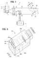
- Fig. 1 is a schematic diagram showing an air-conditioner 1 for a vehicle having a wiring harness according to a first embodiment of the present invention.
- the air-conditioner has an air-conditioner casing 2 as an air passage. Upstream of the airflow in the air-conditioner casing 2, an inside air suction port 3, an outside air suction port 4, and an inside/outside air-switching door 5 are disposed.
- the inside air suction port 3 sucks the inside air inside a compartment of the vehicle.
- the outside sir suction port 4 sucks the outside air outside the compartment.
- the inside/outside air-switching door 5 selectively opens and closes both the inside and outside air suction ports.
- a filter Downstream of the airflow from the inside/outside air-switching door 5, a filter (not shown) and an air blower 7 are disposed.
- the filter removes a dust in the air.
- the air blower 7 sucks the air through the inside and outside air suction ports 3, 4. Then, the sucked air is blown to each air blow port 14, 15, 17 by the air blower 7.
- an evaporator 9 Downstream of the airflow from the air blower 7, an evaporator 9 is disposed.
- the evaporator 9 cools the air blowing into the compartment. All of the air blown by the air blower 7 passes through the evaporator 9.
- a heater 10 Downstream of the airflow from the evaporator 9, a heater 10 is disposed. The heater 10 heats the air blowing into the compartment with using a water coolant of an engine 11 as a heat source.
- a bypass passage 12 is disposed in the air-conditioner casing 2.
- the airflow bypasses the heater 10 with using the bypass passage 12.
- an air-mixing door 13 is disposed upstream of the airflow from the heater 10, an air-mixing door 13 is disposed.
- the air-mixing door 13 controls an airflow ratio between the airflow passing through the heater 10 and the airflow passing through the bypass passage 12 so that the temperature of the air blowing into the compartment is controlled.
- a face mode outlet 14, a foot mode outlet 15, and a defroster mode outlet 17 are disposed on the most downstream of the airflow in the air-conditioner casing 2.
- the air flows from the face mode outlet 14 toward an upper body of a passenger in the compartment.
- the air flows from the foot mode outlet 15 toward a lower body of the passenger in the compartment.
- the air flows from the defroster mode outlet 17 toward a windshield 16 of the vehicle.
- Each air-blow mode switching door 18, 19, 20 is disposed upstream of the airflow from the outlet 14, 15, 17, respectively.
- each actuator M such as a servomotor, respectively.
- each actuator 21 is controlled by an electric control unit (i.e., ECU) 22.
- ECU electric control unit 22.
- Fig. 2 is a block diagram showing a control system of the air-conditioner.
- the ECU 22 includes a communication unit 22a connecting to the actuator 21 disposed outside the ECU 22a. Specifically, the communication unit 22a connects to the actuator 21 through a connector 24 and a pitch ribbon cable 30 as a wiring harness (i.e. , a W/H) connected to the connector 24 .
- An actuator connector (i.e., an electronic connector) 23 is disposed on the other end of the pitch ribbon cable 30 opposite to the connector 24.
- the electronic connector 23 includes an actuator driving unit for driving each actuator such as the inside/outside air switching door 5, the air-mixing door 13, and the air-blow mode switching door 18, 19, 20. Each electronic connector 23 is connected together in series. That is a tandem connection of the electronic connector 23.
- Fig. 3 is a schematic perspective view showing the electronic connector 23, which is disposed on the actuator side of the pitch ribbon cable 30 as the W/H for connecting the ECU 22 and the actuator 21.
- the electronic connector 23 includes a connector housing 23a, a cover 23f, and a female connector 23c.
- the connector housing 23a is made of resin, and has a rectangular solid shape.
- the connector housing 23a accommodates an IC (i.e., an integrated circuit) 23b, the female connector 23c, and a terminal 23h having a harness terminal 23d.
- a motor drive circuit and a communication circuit are integrated in the IC 23b, i.e., they are packed in one chip.
- the motor drive circuit drives the actuator (i.e., a motor M).
- the communication circuit communicates between the motor drive circuit and the ECU 22 with a control signal including an output signal from a potentiometer for controlling the actuator 21.
- the female connector 23c is engaged to a male connector 21d of the actuator 21.
- the harness terminal 23d connects to the pitch ribbon cable 30.
- a press-contact portion 40 is disposed on a top end of the harness terminal 23d.
- the press-contact portion 40 as a press-contact terminal has a V shape notch.
- a coated lead wire 31 of the pitch ribbon cable 30 is inserted in a lead wire opening 23g disposed in a contact plane between the connector housing 23a and a cover 23f so that the lead wire 31 is fixed to the connector housing 23a.
- the lead wire 31 is embedded and engaged to the press-contact portion 40 by the cover 23f so that the lead wire 31 electrically connects to the harness terminal 23d.
- the lead wire 31 of the pitch ribbon cable 30 is embedded in the press-contact portion 40, so that an insulation coat of the lead wire 31 is cut by the press-contact portion 40 having a V-shape. Then, a core wire 31a in the lead wire 31 and the harness terminal 23d are electrically connected together. On the other hand, the pitch ribbon cable 30 is sandwiched between the connector housing 23a and the cover 23f through the lead wire opening so that the pitch ribbon cable 30 is fixed to the electronic connector 23.
- the pitch ribbon cable 30 is connected to the electronic connector 30.
- the pitch ribbon cable 30 is also connected to the connector 24.
- the wiring harness is assembled to the ECU 22, and each actuator in series through the connectors 23, 24, without cutting the bundle of the pitch ribbon cable 30.
- a portion sandwiched between two lead wire openings 23g disposed in the connector housing 23a works as a positioning boss 50 described later.
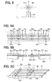
- Figs. 5 show an arrangement of the pitch ribbon cable 30.
- Fig. 5A is a top view showing a part of the pitch ribbon cable 30, Fig. 5B a cross-sectional view, and Fig. 5C a partial perspective view.
- the pitch ribbon cable 30 includes two power source lines (i.e., a positive line and a ground line) and a control line for transmitting a control signal ( i.e. , a multiplex communication signal with using a predetermined protocol).
- the pitch ribbon cable 30 includes three lead wires 31.
- a plurality of lead wires 31 forms a bundle of the wire harness such that each lead wire 31 is disposed at every predetermined pitch (e.g., a full pitch equals to 2.54mm) through a bridge portion 32.
- the insulation coat of the lead wire 31 and the bridge portion 32 are integrally made of resin material such as vinyl chloride resin.
- a plurality of notches 33 is disposed in the bridge portion 32 having a plate shape.
- a group of notches 33 disposed in adjacent bridge portions of the pitch ribbon cable 30 is disposed in alignment with a line along with a direction perpendicularly to a longitudinal direction of the lead wire 31. In other words, each neighboring notch 33 is disposed perpendicularly to the lead wire 31.
- the notch 33 is formed by a punching method for punching a hole having a rectangular shape or a round shape.
- Each notch 33 disposed in one bridge portion 32 is disposed at predetermined intervals in the longitudinal direction of the bridge portion 32, as shown in Fig. 5A.
- another positioning boss 50b is disposed at a predetermined position.
- One is disposed on the electronic connector 23.
- positioning bosses 50a, 50c are disposed on the electronic connector 23.
- the other is disposed on the in-vehicle unit such as the air-conditioner casing 2 and the body of the vehicle, i.e., the positioning boss 50b is the other type of the boss 50.
- the positioning boss 50b of the air-conditioner casing 2 penetrates a notch 33d disposed in the bridge portion 32 of the pitch ribbon cable 30 so that they are engaged together.
- the top end of the positioning boss 50b protruded from the notch 33d is capped by a boss cap 51, so that both the boss 50b and the boss cap 51 are fixed.
- the W/H is fixed to the air-conditioner casing 2 without loosening, so that positioning accuracy of the pitch ribbon cable 30 is improved.
- the W/H has accuracy of layout in case of assembling the W/H to the in-vehicle unit or the body of the vehicle, i.e., the layout of the wiring harness connecting to the in-vehicle unit or the body of the vehicle becomes definite.
- fixation of the pitch ribbon cable 30 is also improved.
- the boss 50b has a column shape shown in Fig. 5A, the boss 50b can have another shape such as a rectangular solid shape.
- notches 33a, 33b, 33c, 33e, 33f are also formed in the bridge portion 32 by punching at predetermined intervals.
- a positioning boss 50a, 50c of the connector 23 penetrates a notch 33b, 33e of the pitch ribbon cable 30 corresponding to the boss 50a, 50c, respectively.
- the boss 50a, 50c is also capped by the cover 23f, so that the pitch ribbon cable 30 is fixed to the electronic connector 23.
- a press-contact portion 40a, 40c of the electronic connector 23 penetrates a corresponding notch 33a, 33f of the pitch ribbon cable 30, so that the electronic connector 23 connects to the pitch ribbon cable 23 electrically.
- the alignment between the press-contact portion 40a, 40c and the notch 33a, 33f can be confirmed, so that the electronic connector 23 is press-contacted and fixed to the pitch ribbon cable 30 at the predetermined position.
- the press-contact position between the lead wire 31 and the corresponding electronic connector 23 becomes definite in case of connecting the pitch ribbon cable 30 and the electronic connector 23. Therefore, the notch 33a, 33f works as a positioning reference for aligning the notch 33a, 33f to the press-contact portion 40a, 40c, so that the press-contact position can be confirmed to align at a predetermined position in the pitch ribbon cable 30.
- the notch 33d which is selected among a plurality of the notches 33 disposed in the bridge 32 of the pitch ribbon cable 30, is engaged to the boss 50b disposed in the air-conditioner casing 2 or the body of the vehicle, so that the W/H is aligned, i.e., attached to the in-vehicle unit and fixed thereto.
- the selected notch 33d is only one notch in this embodiment, a plurality of notches can be selected for being engaged to a plurality of corresponding bosses.
- the press-contact portions 40a, 40c of the electronic connector 23 are aligned at a predetermined position of the pitch ribbon cable 30.
- the engagement position between the positioning bosses 50a, 50c and the notches 33b, 33e works as a positioning reference.
- the positioning bosses 50a, 50c are disposed in the electronic connector 23. Accordingly, the pitch ribbon cable can be assembled to the electronic connector 23 without being loosened.
- the W/H can be aligned without bumping against another movable part. Therefore, a breaking of wire in the W/H and a striking noise are limited to generate.
- the pitch ribbon cable 30 is firstly fixed to the in-vehicle unit or the body of the vehicle, and then the pitch ribbon cable 30 is engaged to the electronic connector 23, so that the W/H is assembled and aligned.
- the pitch ribbon cable 30 can be firstly engaged to the electronic connector 23, and then the pitch ribbon cable 30 is fixed to the in-vehicle unit or the body of the vehicle, so that the W/H is assembled and aligned.
- the pitch ribbon cable 30 necessitates to disconnect to the press-contact portion 40 such as the electronic connector 23.
- a newly selected notch which is neighboring to the previously selected notch 33d and has not been used previously, is engaged to the positioning boss.
- the newly selected notch is selected among a plurality of notches disposed in the pitch ribbon cable 30 at predetermined intervals.
- the new positioning reference of the boss is provided, so that the press-contact portion is also newly provided, i.e., the new press-contact portion is not a previous one.
- a loose connection at the press-contact portion or a disconnection of the lead wire can be limited.
- the pitch ribbon cable 30 as the W/H is used for the air conditioner 1 of the vehicle
- the pitch ribbon cable 30 can be used for another in-vehicle unit such as a power window actuator for opening and closing a door window glass.
- the power window actuator is disposed in a door.
- the notch 33 disposed in the bridge 32 has a rectangular solid shape
- the notch 33 can have another shape such as a round shape.
- the pitch ribbon cable 30 includes a plurality of coated lead wires 31 disposed in parallel and a plurality of bridge portions (i.e., intermediate membranes) 32 formed of a strip-shaped insulation coat 101.
- Each coated lead wire 31 includes a plurality of wires (i. e. , core wires) 31a embedded in the insulation coat 101, and has a cylindrical shape.
- the bridge portion 32 is disposed between the coated lead wires 31, and has a plate shape.
- the core wire 31a is composed of a stranded wire or a single wire, as shown in Fig. 6.
- the terminal 23h of the electronic connector 23 includes a plurality of press-contact portions 40 disposed in parallel at same intervals as the core wires 31a.
- Each press-contact portion 40 has a press-contact groove 141 on the top end of the press-contact portion 40, and has a furcated shape disposed in parallel to a longitudinal direction of the press-contact portion 40.
- a pair of pointed tips 143 is disposed on both sides of the press-contact groove 141. The pointed tips 143 easily penetrate the bridge portion 32.
- a precut portion 105 is disposed in the bridge portion 32, which is nearby a press-contact position for connecting the pitch ribbon cable 30 and the terminal 23h.
- the precut portion 105 has a pair of horseshoe shape or C-shape precuts, each back of which faces each other so as to sandwich the coated lead wire 31.
- the precut portion 105 can be a U-shape, an arc shape, and the like.
- the precut portion 105 works as the notch 33a, 33f shown in Fig. 5A, so that the press-contact position can be confirmed to align at a predetermined position in the pitch ribbon cable 30. Accordingly, the press-contact position between the lead wire 31 and the corresponding electronic connector 23 becomes definite in case of connecting the pitch ribbon cable 30 and the electronic connector 23. Therefore, the precut portion 105 instead of the notch 33a, 33f shown in Fig. 5A works as a positioning reference for aligning the precut portion 105 to the press-contact portion 40, so that the press-contact position can be confirmed to align at a predetermined position in the pitch ribbon cable 30.
- the pitch ribbon cable 30 connects to the terminal 23h with using with a press-contact method such that the pitch ribbon cable 30 is pressed into a plurality of press-contact portions 40, so that the coated lead wire 31 is pressed into the press-contact groove 141.
- a press-contact method such that the pitch ribbon cable 30 is pressed into a plurality of press-contact portions 40, so that the coated lead wire 31 is pressed into the press-contact groove 141.
- both ends of the coated lead wire 31 are cut by an edge of the press-contact groove 141, so that the core wire 31a is connected to the press-contact portion 40 electrically.
- the precut portion 105 arises so that a pair of insulation walls 150 is formed between the press-contact portions 40 by the arisen precut portion 105.
- this W/H provides an excellent insulation performance without any insulation rib disposed between the press-contact portions 40.
- the precut portion 105 has a pair of horseshoe shape or C-shape precuts
- the precut portion 105 can be composed of one horse shape precut and a hole.
- the precut portion 105 provides a single insulation wall 150.
Landscapes
- Coupling Device And Connection With Printed Circuit (AREA)
- Multi-Conductor Connections (AREA)
Abstract
Description
- The present invention relates to a wiring harness for connecting between electric units with using a pitch ribbon cable. Specifically, the wiring harness is suitably used for a vehicle.
- Previously, a wiring harness for connecting between in-vehicle units has a marking tape disposed at a predetermined position of the wiring harness. This wiring harness is disclosed, for example, in Japanese Patent No. 2002-109976. The marking tape shows both the predetermined position as a press-contact position and a corresponding connector in case of manufacturing the wire harness. The corresponding connector is press-contacted and fixed to a certain wire of the wiring harness at the predetermined position. In other words, the marking tape provides to confirm the wire for connecting the corresponding connector among a plurality of wires in the wiring harness.
- If a layout of the wiring harness connecting to an in-vehicle unit or a body of a vehicle is indefinite when the wiring harness is arranged in a predetermined position, alignment accuracy of the connector for connecting to the in-vehicle unit or the body becomes lower. Therefore, in a case where spacing between connectors is comparatively narrow, each connector cannot be installed in the in-vehicle unit or the body. On the other hand, in a case where spacing between connectors is comparatively wide, each connector has an excess allowance so that the wiring harness may loosen. This loose of the wiring harness may cause a striking noise or some kind of trouble. Here, the striking noise at a loose portion is generated by bumping between the connector and the wiring harness because of a vibration of the body of the vehicle. The trouble is, for example, a breaking of wire by getting the wiring harness caught in a movable portion of the in-vehicle unit.
- Thus, the prior art provides to show the press-contact position between the certain wire and the corresponding connector definitely in case of manufacturing the wiring harness. However, the layout of the wiring harness connecting to the in-vehicle unit or the body of the vehicle remains indefinite, when the wiring harness is arranged in the predetermined position in case of assembling the wiring harness to the in-vehicle unit and the body of the vehicle including another connector.
- In view of the above problem, it is an object of the present invention to provide a wiring harness having accuracy of layout in case of assembling the wiring harness to an in-vehicle unit or a body of a vehicle. It is another object of the present invention to provide a wiring harness having an excellent insulation performance.
- A wiring harness for connecting electrically between in-vehicle units includes a pitch ribbon cable having a plurality of bridge portions. Each bridge portion of the pitch ribbon cable includes a plurality of notches for defining a position of the wiring harness.
- In the above wiring harness, the notch is disposed in the bridge portion of the pitch ribbon cable, and the notch is used for defining the position of the wiring harness. Thus, the notch provides a definite layout of the wiring harness attaching to the in-vehicle unit.
- Preferably, the wiring harness further includes a connector having a press-contact portion for engaging the pitch ribbon cable. Here, the notch includes a first notch, which is penetrated by the press-contact portion of the connector. Therefore, the press-contact portion of the connector can be aligned accurately to the first notch of the pitch ribbon cable.
- Preferably, the notch includes a third notch, which engages with a second boss of the in-vehicle unit in case of assembling the wiring harness to the in-vehicle unit. Therefore, the wiring harness itself can be aligned accurately to the in-vehicle unit.
- Preferably, each notch disposed in one bridge portion is disposed in a longitudinal direction of the bridge portion at predetermined intervals. Therefore, the wiring harness has a flexibility of alignment, which provides to align the wiring harness accurately even if position of the press-contact portion or the positioning boss change in various ways.
- Preferably, the first notch is provided by a precut portion for working as an insulation wall in such a manner that the precut portion arises in a case where the first notch is pressed into the press-contact portion so that the arisen precut portion separates between the press-contact portions. This wiring harness has an excellent insulation performance.
- Moreover, another wiring harness for connecting electrically between in-vehicle units includes a pitch ribbon cable having a plurality of bridge portions and a plurality of lead wires and a connector having a first boss and a press-contact portion. Each bridge portion is disposed between two lead wires, and includes first, second and third notches. The third notch is engaged to a second boss of the in-vehicle unit in case of assembling the pitch ribbon cable to the in-vehicle unit so that layout of the wiring harness assembling to the in-vehicle unit becomes definite. The second notch is engaged to the first boss of the connector in case of attaching the pitch ribbon cable to the connector. The first notch is engaged to the press-contact portion of the connector with using the second notch as a positioning reference so that positioning of the pitch ribbon cable attaching to the connector becomes definite.
- In the above wiring harness, the third notch provides a definite layout of the wiring harness attaching to the in-vehicle unit. Moreover, the second notch provides a definite positioning of the pitch ribbon cable attaching to the connector.
- The above and other objects, features and advantages of the present invention will become more apparent from the following detailed description made with reference to the accompanying drawings. In the drawings:
- Fig. 1 is a schematic diagram showing an air-conditioner for a vehicle, according to a first embodiment of the present invention,
- Fig. 2 is a block diagram showing a control system of the air-conditioner, according to the first embodiment,
- Fig. 3 is a schematic perspective view showing an electronic connector, according to the first embodiment,
- Fig. 4 is a partial cross-sectional view showing a press-contact portion as a crimp-style terminal, according to the first embodiment,
- Fig. 5A is a top view, Fig. 5B a cross-sectional view, and Fig. 5C a partial perspective view showing an arrangement of a pitch ribbon cable, according to the first embodiment,
- Fig. 6 is a schematic perspective view showing a press-contact portion between a pitch ribbon cable and a terminal, according to a second embodiment of the present invention, and
- Fig. 7 is a perspective view showing the pitch ribbon cable, according to the second embodiment.
- Fig. 1 is a schematic diagram showing an air-
conditioner 1 for a vehicle having a wiring harness according to a first embodiment of the present invention. The air-conditioner has an air-conditioner casing 2 as an air passage. Upstream of the airflow in the air-conditioner casing 2, an insideair suction port 3, an outsideair suction port 4, and an inside/outside air-switchingdoor 5 are disposed. The insideair suction port 3 sucks the inside air inside a compartment of the vehicle. The outsidesir suction port 4 sucks the outside air outside the compartment. The inside/outside air-switchingdoor 5 selectively opens and closes both the inside and outside air suction ports. - Downstream of the airflow from the inside/outside air-switching
door 5, a filter (not shown) and anair blower 7 are disposed. The filter removes a dust in the air. Theair blower 7 sucks the air through the inside and outsideair suction ports air blow port air blower 7. - Downstream of the airflow from the
air blower 7, an evaporator 9 is disposed. The evaporator 9 cools the air blowing into the compartment. All of the air blown by theair blower 7 passes through the evaporator 9. Downstream of the airflow from the evaporator 9, aheater 10 is disposed. Theheater 10 heats the air blowing into the compartment with using a water coolant of anengine 11 as a heat source. - In the air-
conditioner casing 2, abypass passage 12 is disposed. The airflow bypasses theheater 10 with using thebypass passage 12. Upstream of the airflow from theheater 10, an air-mixingdoor 13 is disposed. The air-mixingdoor 13 controls an airflow ratio between the airflow passing through theheater 10 and the airflow passing through thebypass passage 12 so that the temperature of the air blowing into the compartment is controlled. - On the most downstream of the airflow in the air-
conditioner casing 2, aface mode outlet 14, afoot mode outlet 15, and adefroster mode outlet 17 are disposed. The air flows from theface mode outlet 14 toward an upper body of a passenger in the compartment. The air flows from thefoot mode outlet 15 toward a lower body of the passenger in the compartment. The air flows from thedefroster mode outlet 17 toward awindshield 16 of the vehicle. Each air-blowmode switching door outlet - The air-blow
mode switching doors door 13, and the inside/outside air-switchingdoor 5 are opened and closed by each actuator M such as a servomotor, respectively. As shown in Fig. 2, each actuator 21 is controlled by an electric control unit (i.e., ECU) 22. Here, Fig. 2 is a block diagram showing a control system of the air-conditioner. - The
ECU 22 includes acommunication unit 22a connecting to theactuator 21 disposed outside theECU 22a. Specifically, thecommunication unit 22a connects to theactuator 21 through aconnector 24 and apitch ribbon cable 30 as a wiring harness ( i.e. , a W/H) connected to theconnector 24 . An actuator connector (i.e., an electronic connector) 23 is disposed on the other end of thepitch ribbon cable 30 opposite to theconnector 24. Theelectronic connector 23 includes an actuator driving unit for driving each actuator such as the inside/outsideair switching door 5, the air-mixingdoor 13, and the air-blowmode switching door electronic connector 23 is connected together in series. That is a tandem connection of theelectronic connector 23. - Fig. 3 is a schematic perspective view showing the
electronic connector 23, which is disposed on the actuator side of thepitch ribbon cable 30 as the W/H for connecting theECU 22 and theactuator 21. Theelectronic connector 23 includes aconnector housing 23a, acover 23f, and afemale connector 23c. Theconnector housing 23a is made of resin, and has a rectangular solid shape. Theconnector housing 23a accommodates an IC (i.e., an integrated circuit) 23b, thefemale connector 23c, and a terminal 23h having aharness terminal 23d. A motor drive circuit and a communication circuit are integrated in theIC 23b, i.e., they are packed in one chip. The motor drive circuit drives the actuator (i.e., a motor M). The communication circuit communicates between the motor drive circuit and theECU 22 with a control signal including an output signal from a potentiometer for controlling theactuator 21. Thefemale connector 23c is engaged to a male connector 21d of theactuator 21. Theharness terminal 23d connects to thepitch ribbon cable 30. - As shown in Fig. 4, on a top end of the
harness terminal 23d, a press-contact portion 40 is disposed. The press-contact portion 40 as a press-contact terminal has a V shape notch. Acoated lead wire 31 of thepitch ribbon cable 30 is inserted in alead wire opening 23g disposed in a contact plane between theconnector housing 23a and acover 23f so that thelead wire 31 is fixed to theconnector housing 23a. Moreover, thelead wire 31 is embedded and engaged to the press-contact portion 40 by thecover 23f so that thelead wire 31 electrically connects to theharness terminal 23d. - In other words, the
lead wire 31 of thepitch ribbon cable 30 is embedded in the press-contact portion 40, so that an insulation coat of thelead wire 31 is cut by the press-contact portion 40 having a V-shape. Then, acore wire 31a in thelead wire 31 and theharness terminal 23d are electrically connected together. On the other hand, thepitch ribbon cable 30 is sandwiched between theconnector housing 23a and thecover 23f through the lead wire opening so that thepitch ribbon cable 30 is fixed to theelectronic connector 23. - Thus, the
pitch ribbon cable 30 is connected to theelectronic connector 30. Similarly, thepitch ribbon cable 30 is also connected to theconnector 24. Then, the wiring harness is assembled to theECU 22, and each actuator in series through theconnectors pitch ribbon cable 30. Here, a portion sandwiched between twolead wire openings 23g disposed in theconnector housing 23a works as apositioning boss 50 described later. - Figs. 5 show an arrangement of the
pitch ribbon cable 30. Fig. 5A is a top view showing a part of thepitch ribbon cable 30, Fig. 5B a cross-sectional view, and Fig. 5C a partial perspective view. Thepitch ribbon cable 30 includes two power source lines (i.e., a positive line and a ground line) and a control line for transmitting a control signal ( i.e. , a multiplex communication signal with using a predetermined protocol). In other words, thepitch ribbon cable 30 includes threelead wires 31. A plurality oflead wires 31 forms a bundle of the wire harness such that eachlead wire 31 is disposed at every predetermined pitch (e.g., a full pitch equals to 2.54mm) through abridge portion 32. The insulation coat of thelead wire 31 and thebridge portion 32 are integrally made of resin material such as vinyl chloride resin. - A plurality of
notches 33 is disposed in thebridge portion 32 having a plate shape. A group ofnotches 33 disposed in adjacent bridge portions of thepitch ribbon cable 30 is disposed in alignment with a line along with a direction perpendicularly to a longitudinal direction of thelead wire 31. In other words, each neighboringnotch 33 is disposed perpendicularly to thelead wire 31. Thenotch 33 is formed by a punching method for punching a hole having a rectangular shape or a round shape. Eachnotch 33 disposed in onebridge portion 32 is disposed at predetermined intervals in the longitudinal direction of thebridge portion 32, as shown in Fig. 5A. - In the air-
conditioner casing 2 of the air-conditioner 1 and the body of the vehicle (not shown), anotherpositioning boss 50b is disposed at a predetermined position. In other words, there are two types of theboss 50. One is disposed on theelectronic connector 23. For example, positioningbosses electronic connector 23. The other is disposed on the in-vehicle unit such as the air-conditioner casing 2 and the body of the vehicle, i.e., thepositioning boss 50b is the other type of theboss 50. When the W/H is assembled, i.e., attached to the air-conditioner casing 2, thepositioning boss 50b of the air-conditioner casing 2 penetrates anotch 33d disposed in thebridge portion 32 of thepitch ribbon cable 30 so that they are engaged together. In this case, the top end of thepositioning boss 50b protruded from thenotch 33d is capped by aboss cap 51, so that both theboss 50b and theboss cap 51 are fixed. - Therefore, the W/H is fixed to the air-
conditioner casing 2 without loosening, so that positioning accuracy of thepitch ribbon cable 30 is improved. Thus, the W/H has accuracy of layout in case of assembling the W/H to the in-vehicle unit or the body of the vehicle, i.e., the layout of the wiring harness connecting to the in-vehicle unit or the body of the vehicle becomes definite. Moreover, fixation of thepitch ribbon cable 30 is also improved. Although theboss 50b has a column shape shown in Fig. 5A, theboss 50b can have another shape such as a rectangular solid shape. -
Other notches bridge portion 32 by punching at predetermined intervals. Apositioning boss connector 23 penetrates anotch pitch ribbon cable 30 corresponding to theboss boss cover 23f, so that thepitch ribbon cable 30 is fixed to theelectronic connector 23. Simultaneously, as described before, a press-contact portion electronic connector 23 penetrates acorresponding notch pitch ribbon cable 30, so that theelectronic connector 23 connects to thepitch ribbon cable 23 electrically. - Thus, the alignment between the press-
contact portion notch electronic connector 23 is press-contacted and fixed to thepitch ribbon cable 30 at the predetermined position. In other words, the press-contact position between thelead wire 31 and the correspondingelectronic connector 23 becomes definite in case of connecting thepitch ribbon cable 30 and theelectronic connector 23. Therefore, thenotch notch contact portion pitch ribbon cable 30. - In the W/H according to this embodiment, in a case where the W/H is assembled to the body of the vehicle or the in-vehicle unit such as the air-
conditioner casing 2, firstly thenotch 33d, which is selected among a plurality of thenotches 33 disposed in thebridge 32 of thepitch ribbon cable 30, is engaged to theboss 50b disposed in the air-conditioner casing 2 or the body of the vehicle, so that the W/H is aligned, i.e., attached to the in-vehicle unit and fixed thereto. Although the selectednotch 33d is only one notch in this embodiment, a plurality of notches can be selected for being engaged to a plurality of corresponding bosses. - After the fixation of the selected
notch 33d, the press-contact portions electronic connector 23 are aligned at a predetermined position of thepitch ribbon cable 30. In this case, the engagement position between thepositioning bosses notches positioning bosses electronic connector 23. Accordingly, the pitch ribbon cable can be assembled to theelectronic connector 23 without being loosened. Moreover, the W/H can be aligned without bumping against another movable part. Therefore, a breaking of wire in the W/H and a striking noise are limited to generate. - In this embodiment, the
pitch ribbon cable 30 is firstly fixed to the in-vehicle unit or the body of the vehicle, and then thepitch ribbon cable 30 is engaged to theelectronic connector 23, so that the W/H is assembled and aligned. However, thepitch ribbon cable 30 can be firstly engaged to theelectronic connector 23, and then thepitch ribbon cable 30 is fixed to the in-vehicle unit or the body of the vehicle, so that the W/H is assembled and aligned. - Here, in a case where the in-vehicle unit is checked up or repaired, the
pitch ribbon cable 30 necessitates to disconnect to the press-contact portion 40 such as theelectronic connector 23. In this case, it is preferable not to reuse thepitch ribbon cable 30 so as to align the same portion of thepitch ribbon cable 30 to the press-contact position again, because a loose connection or a disconnection of the lead wire may occur. - Therefore, a newly selected notch, which is neighboring to the previously selected
notch 33d and has not been used previously, is engaged to the positioning boss. The newly selected notch is selected among a plurality of notches disposed in thepitch ribbon cable 30 at predetermined intervals. Thus, the new positioning reference of the boss is provided, so that the press-contact portion is also newly provided, i.e., the new press-contact portion is not a previous one. Thus, a loose connection at the press-contact portion or a disconnection of the lead wire can be limited. - Although the
pitch ribbon cable 30 as the W/H is used for theair conditioner 1 of the vehicle, thepitch ribbon cable 30 can be used for another in-vehicle unit such as a power window actuator for opening and closing a door window glass. Here, the power window actuator is disposed in a door. - Although the
notch 33 disposed in thebridge 32 has a rectangular solid shape, thenotch 33 can have another shape such as a round shape. - A wiring harness according to a second embodiment of the present invention is shown in Figs. 6 and 7. The
pitch ribbon cable 30 includes a plurality of coatedlead wires 31 disposed in parallel and a plurality of bridge portions (i.e., intermediate membranes) 32 formed of a strip-shapedinsulation coat 101. Eachcoated lead wire 31 includes a plurality of wires ( i. e. , core wires) 31a embedded in theinsulation coat 101, and has a cylindrical shape. Thebridge portion 32 is disposed between thecoated lead wires 31, and has a plate shape. Thecore wire 31a is composed of a stranded wire or a single wire, as shown in Fig. 6. - The terminal 23h of the
electronic connector 23 includes a plurality of press-contact portions 40 disposed in parallel at same intervals as thecore wires 31a. Each press-contact portion 40 has a press-contact groove 141 on the top end of the press-contact portion 40, and has a furcated shape disposed in parallel to a longitudinal direction of the press-contact portion 40. A pair ofpointed tips 143 is disposed on both sides of the press-contact groove 141. The pointedtips 143 easily penetrate thebridge portion 32. - A
precut portion 105 is disposed in thebridge portion 32, which is nearby a press-contact position for connecting thepitch ribbon cable 30 and the terminal 23h. Theprecut portion 105 has a pair of horseshoe shape or C-shape precuts, each back of which faces each other so as to sandwich thecoated lead wire 31. Theprecut portion 105 can be a U-shape, an arc shape, and the like. - Here, the
precut portion 105 works as thenotch pitch ribbon cable 30. Accordingly, the press-contact position between thelead wire 31 and the correspondingelectronic connector 23 becomes definite in case of connecting thepitch ribbon cable 30 and theelectronic connector 23. Therefore, theprecut portion 105 instead of thenotch precut portion 105 to the press-contact portion 40, so that the press-contact position can be confirmed to align at a predetermined position in thepitch ribbon cable 30. - The
pitch ribbon cable 30 connects to the terminal 23h with using with a press-contact method such that thepitch ribbon cable 30 is pressed into a plurality of press-contact portions 40, so that thecoated lead wire 31 is pressed into the press-contact groove 141. When thepitch ribbon cable 30 is pressed into the press-contact portion 40, both ends of thecoated lead wire 31 are cut by an edge of the press-contact groove 141, so that thecore wire 31a is connected to the press-contact portion 40 electrically. Simultaneously, theprecut portion 105 arises so that a pair ofinsulation walls 150 is formed between the press-contact portions 40 by the arisenprecut portion 105. - Therefore, this W/H provides an excellent insulation performance without any insulation rib disposed between the press-
contact portions 40. - Although the
precut portion 105 has a pair of horseshoe shape or C-shape precuts, theprecut portion 105 can be composed of one horse shape precut and a hole. In this case, theprecut portion 105 provides asingle insulation wall 150. - Such changes and modifications are to be understood as being within the scope of the present invention as def ined by the appended claims.
Claims (11)
- A wiring harness for connecting electrically between in-vehicle units (5, 13, 18-20), the wiring harness comprising:a pitch ribbon cable (30) having a plurality of bridge portions (32),wherein each bridge portion (32) of the pitch ribbon cable (30) includes a plurality of notches (33, 33a-33f) for defining a position of the wiring harness.
- The wiring harness according to claim 1, further comprising:a connector (23, 24) having a press-contact portion (40, 40a, 40c) for engaging the pitch ribbon cable (30),wherein the notch (33a, 33f) includes a first notch (33a, 33f), which is penetrated by the press-contact portion (40, 40a, 40c) of the connector (23, 24).
- The wiring harness according to claim 1 or 2,
wherein the notch (33b, 33e) includes a second notch (33b, 33e), which engages with a first boss (50a, 50c) of the connector (23, 24) in case of attaching the connector (23, 24) to the pitch ribbon cable (30) so that the second notch (33b, 33e) works as a positioning reference of the press-contact portion (40, 40a, 40c), and
wherein the first notch (33a, 33e) is disposed at a predetermined distance from the second notch (33a, 33e). - The wiring harness according to any one of claims 1-3,
wherein the notch (33c, 33d) includes a third notch (33c, 33d), which engages with a second boss (50b) of the in-vehicle unit (5, 13, 18-20) in case of assembling the wiring harness to the in-vehicle unit (5, 13, 18-20). - The wiring harness according to any one of claims 1-4,
wherein each neighboring notch (33, 33a-33f) disposed in adjacent bridge portions (32) is disposed in alignment with a line perpendicularly to a longitudinal direction of the pitch ribbon cable (30). - The wiring harness according to any one of claims 1-5,
wherein each notch (33, 33a-33f) disposed in one bridge portion (32) is disposed in a longitudinal direction of the bridge portion (32) at predetermined intervals. - The wiring harness according to any one of claims 1-6,
wherein the pitch ribbon cable (30) connects to an electric circuit (23b) disposed in the connector (23) for driving a control actuator (21) with multiplex communication, the actuator (21) controlling a switching door (5) in a vehicle air-conditioner (1). - The wiring harness according to any one of claims 2-7,
wherein the first notch (33a, 33f) is provided by a precut portion (105) for working as an insulation wall (150) in such a manner that the precut portion (105) arises in a case where the first notch (33a, 33f) is pressed into the press-contact portion (40, 40a, 40c) so that the arisen precut portion (105) separates between the press-contact portions (40, 40a, 40c). - The wiring harness according to claim 8,
wherein the precut portion (105) has a pair of horseshoe shape or C-shape precuts, each back of which faces each other so as to sandwich the press-contact portion (40, 40a, 40c). - A wiring harness for connecting electrically between in-vehicle units (5, 13, 18-20), the wiring harness comprising:a pitch ribbon cable (30) having a plurality of bridge portions (32) and a plurality of lead wires (31); anda connector (23) having a first boss (50a, 50c) and a press-contact portion (40, 40a, 40c),wherein each bridge portion (32) is disposed between two lead wires (31), and includes first, second and third notches (33, 33a-33f),
wherein the third notch (33c, 33d) is engaged to a second boss (50b) of the in-vehicle unit (5, 13, 18-20) in case of assembling the pitch ribbon cable (30) to the in-vehicle unit (5, 13, 18-20) so that layout of the wiring harness assembling to the in-vehicle unit (5, 13, 18-20) becomes definite,
wherein the second notch (33b, 33e) is engaged to the first boss (50a, 50c) of the connector (23) in case of attaching the pitch ribbon cable (30) to the connector (23), and
wherein the first notch (33a, 33f) is engaged to the press-contact portion (40, 40a, 40c) of the connector (23) with using the second notch (33b, 33e) as a positioning reference so that positioning of the pitch ribbon cable (30) attaching to the connector (23) becomes definite. - The wiring harness according to claim 10,
wherein the lead wire (31) connects to the press-contact portion (40, 40a, 40c) with using a press-contact method.
Applications Claiming Priority (4)
| Application Number | Priority Date | Filing Date | Title |
|---|---|---|---|
| JP2002305865 | 2002-10-21 | ||
| JP2002305865A JP3891093B2 (en) | 2002-10-21 | 2002-10-21 | Wire harness |
| JP2002361735A JP3912271B2 (en) | 2002-12-13 | 2002-12-13 | Pitch ribbon wire connection structure |
| JP2002361735 | 2002-12-13 |
Publications (2)
| Publication Number | Publication Date |
|---|---|
| EP1414048A1 true EP1414048A1 (en) | 2004-04-28 |
| EP1414048B1 EP1414048B1 (en) | 2007-02-28 |
Family
ID=32072519
Family Applications (1)
| Application Number | Title | Priority Date | Filing Date |
|---|---|---|---|
| EP03023847A Expired - Lifetime EP1414048B1 (en) | 2002-10-21 | 2003-10-20 | Wiring harness |
Country Status (3)
| Country | Link |
|---|---|
| US (1) | US6972375B2 (en) |
| EP (1) | EP1414048B1 (en) |
| DE (1) | DE60312100T2 (en) |
Cited By (1)
| Publication number | Priority date | Publication date | Assignee | Title |
|---|---|---|---|---|
| EP2744064A4 (en) * | 2011-08-11 | 2015-11-25 | Yazaki Corp | POWER SUPPLY DEVICE |
Families Citing this family (14)
| Publication number | Priority date | Publication date | Assignee | Title |
|---|---|---|---|---|
| JP2004268630A (en) * | 2003-03-05 | 2004-09-30 | Yazaki Corp | Electrical connector and auxiliary module |
| JP2005005148A (en) | 2003-06-12 | 2005-01-06 | Denso Corp | Connector for electric actuator |
| JP2006222735A (en) * | 2005-02-10 | 2006-08-24 | Sharp Corp | Communication equipment |
| JP4346592B2 (en) * | 2005-03-09 | 2009-10-21 | 古河電気工業株式会社 | Communication control IC built-in connector and wiring body with communication control IC built-in connector |
| DE102006039604A1 (en) * | 2006-08-24 | 2008-02-28 | Weidmüller Interface GmbH & Co. KG | Cable, connector with cable and method of making the cable |
| JP5324840B2 (en) * | 2008-06-25 | 2013-10-23 | 矢崎総業株式会社 | Wire harness |
| US8039997B2 (en) * | 2009-02-04 | 2011-10-18 | Thermocabinet, Llc | Power supply strip for electronic equipment |
| JP5875098B2 (en) * | 2011-06-30 | 2016-03-02 | 矢崎総業株式会社 | Wire harness structure and electronic device control system |
| JP5785803B2 (en) * | 2011-07-04 | 2015-09-30 | 矢崎総業株式会社 | Wire harness structure and electronic control unit |
| US10590855B2 (en) * | 2015-02-03 | 2020-03-17 | United Technologies Corporation | Distributed electrical architecture for a gas turbine engine |
| JP6490624B2 (en) * | 2016-06-29 | 2019-03-27 | 矢崎総業株式会社 | Wire harness |
| JP6507138B2 (en) * | 2016-10-27 | 2019-04-24 | 矢崎総業株式会社 | Branch structure and wire harness |
| JP2019089398A (en) * | 2017-11-13 | 2019-06-13 | 矢崎総業株式会社 | Electric wire wiring structure and vehicle circuit |
| US10186789B1 (en) | 2018-04-13 | 2019-01-22 | Rustcraft Industries LLC | Keyed cable and connector system |
Citations (8)
| Publication number | Priority date | Publication date | Assignee | Title |
|---|---|---|---|---|
| CH389056A (en) * | 1961-06-05 | 1965-03-15 | Burndy Corp | Connection device for electric cable |
| US3848946A (en) * | 1970-05-30 | 1974-11-19 | Ferranti Ltd | Electric connectors |
| FR2431202A1 (en) * | 1978-07-14 | 1980-02-08 | Raychem Gmbh | PLUG CONNECTION FOR FLAT CABLES, METHOD FOR PRODUCING SAME AND CABLE SUITABLE FOR SUCH CONNECTION |
| EP0283119A2 (en) * | 1987-03-16 | 1988-09-21 | Molex Incorporated | Zero insertion force connector for flexible flat cable |
| US5064382A (en) * | 1989-09-08 | 1991-11-12 | Amp Incorporated | Detonator connector system |
| US5324203A (en) * | 1990-11-30 | 1994-06-28 | Yazaki Corporation | Electrical harnessing structure for vehicle |
| US5344332A (en) * | 1993-06-03 | 1994-09-06 | Storage Technology Corporation | Apparatus and method for floatable electrical connection of semi-rigidly mounted devices |
| JP2002208325A (en) * | 2001-01-10 | 2002-07-26 | Auto Network Gijutsu Kenkyusho:Kk | Flat cable and its positioning |
Family Cites Families (9)
| Publication number | Priority date | Publication date | Assignee | Title |
|---|---|---|---|---|
| US3214723A (en) * | 1961-06-05 | 1965-10-26 | Burndy Corp | Tape cable connector |
| US3355099A (en) * | 1961-06-05 | 1967-11-28 | Victor Comptometer Corp | Spring detent |
| US3920301A (en) * | 1972-11-28 | 1975-11-18 | Amp Inc | Electrical connectors for flat cable and methods of making same |
| US4416111A (en) * | 1981-02-25 | 1983-11-22 | The United States Of America As Represented By The Administrator Of The National Aeronautics And Space Administration | Air modulation apparatus |
| JPH01177813A (en) * | 1988-01-07 | 1989-07-14 | Mirai Ind Co Ltd | Floor wiring structure |
| JP3601888B2 (en) * | 1995-10-19 | 2004-12-15 | カルソニックカンセイ株式会社 | Automotive air conditioners |
| JP2002109976A (en) | 2000-10-03 | 2002-04-12 | Yonezawa Densen Kk | Wire harness and wire press bonding position identifying method |
| JP2002246090A (en) * | 2001-02-13 | 2002-08-30 | Sunx Ltd | Connector for parallel multi-core cable |
| JP2004180486A (en) * | 2002-09-30 | 2004-06-24 | Fujikura Ltd | Flat harness fixing structure |
-
2003
- 2003-10-15 US US10/686,117 patent/US6972375B2/en not_active Expired - Fee Related
- 2003-10-20 DE DE60312100T patent/DE60312100T2/en not_active Expired - Lifetime
- 2003-10-20 EP EP03023847A patent/EP1414048B1/en not_active Expired - Lifetime
Patent Citations (8)
| Publication number | Priority date | Publication date | Assignee | Title |
|---|---|---|---|---|
| CH389056A (en) * | 1961-06-05 | 1965-03-15 | Burndy Corp | Connection device for electric cable |
| US3848946A (en) * | 1970-05-30 | 1974-11-19 | Ferranti Ltd | Electric connectors |
| FR2431202A1 (en) * | 1978-07-14 | 1980-02-08 | Raychem Gmbh | PLUG CONNECTION FOR FLAT CABLES, METHOD FOR PRODUCING SAME AND CABLE SUITABLE FOR SUCH CONNECTION |
| EP0283119A2 (en) * | 1987-03-16 | 1988-09-21 | Molex Incorporated | Zero insertion force connector for flexible flat cable |
| US5064382A (en) * | 1989-09-08 | 1991-11-12 | Amp Incorporated | Detonator connector system |
| US5324203A (en) * | 1990-11-30 | 1994-06-28 | Yazaki Corporation | Electrical harnessing structure for vehicle |
| US5344332A (en) * | 1993-06-03 | 1994-09-06 | Storage Technology Corporation | Apparatus and method for floatable electrical connection of semi-rigidly mounted devices |
| JP2002208325A (en) * | 2001-01-10 | 2002-07-26 | Auto Network Gijutsu Kenkyusho:Kk | Flat cable and its positioning |
Non-Patent Citations (1)
| Title |
|---|
| PATENT ABSTRACTS OF JAPAN vol. 2002, no. 11 6 November 2002 (2002-11-06) * |
Cited By (2)
| Publication number | Priority date | Publication date | Assignee | Title |
|---|---|---|---|---|
| EP2744064A4 (en) * | 2011-08-11 | 2015-11-25 | Yazaki Corp | POWER SUPPLY DEVICE |
| US9545889B2 (en) | 2011-08-11 | 2017-01-17 | Yazaki Corporation | Power supply unit |
Also Published As
| Publication number | Publication date |
|---|---|
| DE60312100T2 (en) | 2007-10-31 |
| EP1414048B1 (en) | 2007-02-28 |
| US6972375B2 (en) | 2005-12-06 |
| US20040074665A1 (en) | 2004-04-22 |
| DE60312100D1 (en) | 2007-04-12 |
Similar Documents
| Publication | Publication Date | Title |
|---|---|---|
| EP1414048B1 (en) | Wiring harness | |
| US6048020A (en) | Electrical interconnection module for vehicle instrument panel | |
| US6991496B2 (en) | Electrical connector | |
| CN101312277B (en) | Communication Relay Equipment and Relay Connector Units | |
| EP1018783B1 (en) | Electrical junction box having a bus bar | |
| CN102596647B (en) | Wiring Harnesses and Electronics Control Systems | |
| US7572149B2 (en) | Connector | |
| US20020157847A1 (en) | Junction box and junction box forming method | |
| US4910641A (en) | Wire harness apparatus for instrument panel | |
| JPH1059134A (en) | Drive unit for car screen wiper | |
| US7470130B2 (en) | Junction box having components combined to an inner cover | |
| US7059889B1 (en) | Splice block for interconnecting electrical conductors | |
| JP2003134720A (en) | Actuator connector | |
| JP3891093B2 (en) | Wire harness | |
| JP2004273683A (en) | Electronic unit with connector and method of manufacturing the same | |
| US11942712B2 (en) | Substrate unit and manufacturing method of substrate unit | |
| EP1428727B1 (en) | Wiring structure using wiring harness for automobile | |
| CN110998196A (en) | Outdoor unit of air conditioner | |
| JP2007282399A (en) | Electrical junction box | |
| EP0768212A2 (en) | Control module | |
| JP2008503862A (en) | Device for connecting basic electrical components and auxiliary electrical components, in particular to an automobile track network, and a method for manufacturing such a connection device | |
| JP2709621B2 (en) | Instrument panel wiring structure | |
| JPS62265048A (en) | Car wiring | |
| JP2005138734A (en) | In-vehicle air conditioner | |
| JPH07296910A (en) | Wiring harness |
Legal Events
| Date | Code | Title | Description |
|---|---|---|---|
| PUAI | Public reference made under article 153(3) epc to a published international application that has entered the european phase |
Free format text: ORIGINAL CODE: 0009012 |
|
| 17P | Request for examination filed |
Effective date: 20040210 |
|
| AK | Designated contracting states |
Kind code of ref document: A1 Designated state(s): AT BE BG CH CY CZ DE DK EE ES FI FR GB GR HU IE IT LI LU MC NL PT RO SE SI SK TR |
|
| AX | Request for extension of the european patent |
Extension state: AL LT LV MK |
|
| 17Q | First examination report despatched |
Effective date: 20040810 |
|
| AKX | Designation fees paid |
Designated state(s): DE FR GB |
|
| GRAP | Despatch of communication of intention to grant a patent |
Free format text: ORIGINAL CODE: EPIDOSNIGR1 |
|
| GRAS | Grant fee paid |
Free format text: ORIGINAL CODE: EPIDOSNIGR3 |
|
| GRAA | (expected) grant |
Free format text: ORIGINAL CODE: 0009210 |
|
| AK | Designated contracting states |
Kind code of ref document: B1 Designated state(s): DE FR GB |
|
| REG | Reference to a national code |
Ref country code: GB Ref legal event code: FG4D |
|
| REF | Corresponds to: |
Ref document number: 60312100 Country of ref document: DE Date of ref document: 20070412 Kind code of ref document: P |
|
| ET | Fr: translation filed | ||
| PLBE | No opposition filed within time limit |
Free format text: ORIGINAL CODE: 0009261 |
|
| STAA | Information on the status of an ep patent application or granted ep patent |
Free format text: STATUS: NO OPPOSITION FILED WITHIN TIME LIMIT |
|
| 26N | No opposition filed |
Effective date: 20071129 |
|
| PGFP | Annual fee paid to national office [announced via postgrant information from national office to epo] |
Ref country code: FR Payment date: 20091029 Year of fee payment: 7 Ref country code: GB Payment date: 20091014 Year of fee payment: 7 |
|
| GBPC | Gb: european patent ceased through non-payment of renewal fee |
Effective date: 20101020 |
|
| PG25 | Lapsed in a contracting state [announced via postgrant information from national office to epo] |
Ref country code: FR Free format text: LAPSE BECAUSE OF NON-PAYMENT OF DUE FEES Effective date: 20101102 |
|
| REG | Reference to a national code |
Ref country code: FR Ref legal event code: ST Effective date: 20110630 |
|
| PG25 | Lapsed in a contracting state [announced via postgrant information from national office to epo] |
Ref country code: GB Free format text: LAPSE BECAUSE OF NON-PAYMENT OF DUE FEES Effective date: 20101020 |
|
| PGFP | Annual fee paid to national office [announced via postgrant information from national office to epo] |
Ref country code: DE Payment date: 20141022 Year of fee payment: 12 |
|
| REG | Reference to a national code |
Ref country code: DE Ref legal event code: R119 Ref document number: 60312100 Country of ref document: DE |
|
| PG25 | Lapsed in a contracting state [announced via postgrant information from national office to epo] |
Ref country code: DE Free format text: LAPSE BECAUSE OF NON-PAYMENT OF DUE FEES Effective date: 20160503 |