EP1414039A1 - Magnetic tape cartridge - Google Patents
Magnetic tape cartridge Download PDFInfo
- Publication number
- EP1414039A1 EP1414039A1 EP20030028750 EP03028750A EP1414039A1 EP 1414039 A1 EP1414039 A1 EP 1414039A1 EP 20030028750 EP20030028750 EP 20030028750 EP 03028750 A EP03028750 A EP 03028750A EP 1414039 A1 EP1414039 A1 EP 1414039A1
- Authority
- EP
- European Patent Office
- Prior art keywords
- magnetic tape
- leader pin
- case
- lock
- lock member
- Prior art date
- Legal status (The legal status is an assumption and is not a legal conclusion. Google has not performed a legal analysis and makes no representation as to the accuracy of the status listed.)
- Granted
Links
- 230000002708 enhancing effect Effects 0.000 abstract description 6
- 230000001105 regulatory effect Effects 0.000 description 17
- 239000002184 metal Substances 0.000 description 9
- 238000003825 pressing Methods 0.000 description 8
- 238000004519 manufacturing process Methods 0.000 description 6
- 230000004048 modification Effects 0.000 description 5
- 238000012986 modification Methods 0.000 description 5
- 230000001070 adhesive effect Effects 0.000 description 4
- 238000004804 winding Methods 0.000 description 4
- 239000002985 plastic film Substances 0.000 description 3
- 239000011347 resin Substances 0.000 description 3
- 229920005989 resin Polymers 0.000 description 3
- 229910001220 stainless steel Inorganic materials 0.000 description 3
- 239000010935 stainless steel Substances 0.000 description 3
- 230000004323 axial length Effects 0.000 description 2
- 238000005520 cutting process Methods 0.000 description 2
- -1 etc.) Substances 0.000 description 2
- 239000005001 laminate film Substances 0.000 description 2
- 239000000314 lubricant Substances 0.000 description 2
- 239000000463 material Substances 0.000 description 2
- 229920000728 polyester Polymers 0.000 description 2
- 238000003860 storage Methods 0.000 description 2
- 230000001154 acute effect Effects 0.000 description 1
- 239000000853 adhesive Substances 0.000 description 1
- 239000012790 adhesive layer Substances 0.000 description 1
- 238000005452 bending Methods 0.000 description 1
- 239000011248 coating agent Substances 0.000 description 1
- 238000000576 coating method Methods 0.000 description 1
- 238000010276 construction Methods 0.000 description 1
- 230000003247 decreasing effect Effects 0.000 description 1
- 229920001971 elastomer Polymers 0.000 description 1
- 239000000806 elastomer Substances 0.000 description 1
- 239000006260 foam Substances 0.000 description 1
- 238000003780 insertion Methods 0.000 description 1
- 230000037431 insertion Effects 0.000 description 1
- 239000010410 layer Substances 0.000 description 1
- 238000000034 method Methods 0.000 description 1
- 238000000465 moulding Methods 0.000 description 1
- 229920006255 plastic film Polymers 0.000 description 1
- 230000001012 protector Effects 0.000 description 1
Images





Classifications
-
- G—PHYSICS
- G11—INFORMATION STORAGE
- G11B—INFORMATION STORAGE BASED ON RELATIVE MOVEMENT BETWEEN RECORD CARRIER AND TRANSDUCER
- G11B23/00—Record carriers not specific to the method of recording or reproducing; Accessories, e.g. containers, specially adapted for co-operation with the recording or reproducing apparatus ; Intermediate mediums; Apparatus or processes specially adapted for their manufacture
- G11B23/02—Containers; Storing means both adapted to cooperate with the recording or reproducing means
- G11B23/037—Single reels or spools
-
- G—PHYSICS
- G11—INFORMATION STORAGE
- G11B—INFORMATION STORAGE BASED ON RELATIVE MOVEMENT BETWEEN RECORD CARRIER AND TRANSDUCER
- G11B23/00—Record carriers not specific to the method of recording or reproducing; Accessories, e.g. containers, specially adapted for co-operation with the recording or reproducing apparatus ; Intermediate mediums; Apparatus or processes specially adapted for their manufacture
- G11B23/20—Record carriers not specific to the method of recording or reproducing; Accessories, e.g. containers, specially adapted for co-operation with the recording or reproducing apparatus ; Intermediate mediums; Apparatus or processes specially adapted for their manufacture with provision for splicing to provide permanent or temporary connections
- G11B23/26—Record carriers not specific to the method of recording or reproducing; Accessories, e.g. containers, specially adapted for co-operation with the recording or reproducing apparatus ; Intermediate mediums; Apparatus or processes specially adapted for their manufacture with provision for splicing to provide permanent or temporary connections of leaders for loading or threading, e.g. to form a temporary connection
-
- G—PHYSICS
- G11—INFORMATION STORAGE
- G11B—INFORMATION STORAGE BASED ON RELATIVE MOVEMENT BETWEEN RECORD CARRIER AND TRANSDUCER
- G11B23/00—Record carriers not specific to the method of recording or reproducing; Accessories, e.g. containers, specially adapted for co-operation with the recording or reproducing apparatus ; Intermediate mediums; Apparatus or processes specially adapted for their manufacture
- G11B23/02—Containers; Storing means both adapted to cooperate with the recording or reproducing means
- G11B23/04—Magazines; Cassettes for webs or filaments
- G11B23/08—Magazines; Cassettes for webs or filaments for housing webs or filaments having two distinct ends
- G11B23/107—Magazines; Cassettes for webs or filaments for housing webs or filaments having two distinct ends using one reel or core, one end of the record carrier coming out of the magazine or cassette
Definitions
- the present invention relates to a magnetic tape cartridge, in which a single tape reel with magnetic tape wound thereon is rotatably housed within a cartridge case, and in which a leader pin for pulling the magnetic tape out of the cartridge case is affixed to the leading end of the magnetic tape.
- a leader pin (tape pulling-out tool) is affixed to the leading end portion of the magnetic tape to pull the magnetic tape out of the cartridge case.
- This leader pin is held and pulled out by a hold member of a drive unit provided on the side of a recording-reproducing apparatus, whereby forward winding or reverse winding of the magnetic tape is performed.
- Uniting of the leader pin and the magnetic tape can be performed by winding the magnetic tape on the outer periphery of the tape clamp shaft portion of the leader pin and then elastically fitting a clamp member with a C cross section onto the tape clamp portion to clamp the leading end portion of the magnetic tape therebetween.
- the coefficient of friction between the magnetic tape and the leader pin is low and therefore there is a possibility that because of insufficient clamping force, the leader pin will be disengaged from the magnetic tape.
- the present invention has been made in view of the points mentioned above. Accordingly, it is a primary object of the present invention to provide a magnetic tape cartridge that is capable of enhancing the clamping force of the magnetic tape with respect to the leader pin to assure reliability.
- the aforementioned leader member is detachably held in the cartridge case by a lock member, called a shaft holding portion, which has an engaging function, as shown in Fig. 6 of the aforementioned Japanese Unexamined Patent Publication No. 11(1999)-232838. It is advantageous from the viewpoint of structural simplification to employ a spring member to hold the leader member.
- a leader pin 5 affixed to the leading end of magnetic tape 6 is pulled in and out through an opening 10 formed in the side surfaces of an upper case (not shown) and a lower case 3.
- upper and lower housing recesses 20 are formed in the bottom surface of the upper case and the top surface of the lower case 3, and the upper and lower end portions of the leader pin 5 are held in the housing recesses 20.
- a tapered lower guide portion 21 is provided from the lower housing recess 20 toward the opening 10.
- a lock member 50 for detachably holding the leader pin 50 in the housing recesses 20, is symmetrical in the vertical direction thereof and formed into a U-shape, as shown in Fig. 16.
- the lock member 50 has a mounting portion 50a, which is clamped between a mounting boss 51 erected in the bottom surface of the lower case 3 and the side wall 3b of the lower case 3, along the side wall 3b.
- the lock member 50 also has upper and lower elastic arm portions 50b, 50b extending from the forwardly curved rear portion of the mounting portion 50a toward the opening 10.
- the elastic arm portions 50b, 50b have leader-pin holding portions 50c, 50c at their outer ends, respectively.
- leader-pin holding portions 50c, 50c abut the upper and lower end portions of the leader pin 5, respectively.
- Each leader-pin holding portion 50 is bent and has an outer inclined surface which is contacted and deformed by the leader pin 5 being inserted through the opening 10, and an inner inclined surface with which the leader pin is pressed against and held in the housing recess 20.
- the lock member 50 is bent into a deeply curved U-shape by pressing a plate spring, so it is difficult to accurately form an angle ⁇ (see Fig. 16) which the mounting portion 50a forms with the elastic arm portion 50b.
- the amount of deformation in pressing and holding the leader pin 5 varies and therefore the holding force of the lock member 50 with respect to the leader pin 5 tends to vary.
- the deep U-shape pressing requires a plurality of press operations and increases the number of manufacturing steps. Since the deep U-shape pressing makes the length of the elastic arm portion 50b longer and thus increases the developed area, a large quantity of plate spring material is discarded after the stamping operation. Thus, the deeply U-shaped lock member 50 is disadvantageous in terms of cost.
- lock members 50 when a large number of lock members 50 are stored, they are stacked and engaged with one another, if each lock member 50 has a deeply curved U-shape. Since it is difficult to separate them from each other, there is the problem that feeding them serially by a part feeder may become difficult.
- the plate-shaped lock member 50 is assembled into the cartridge case 4, depending on the locking structure there is a possibility that the upper case cannot be closed to the lower case 3. That is, when the lock member 50 is set to the lower case 3, and the upper case is stacked on the lower case 3, the lock member 50 tilts and cannot engage with the mounting boss 51 of the upper case and abut the lower end of the mounting boss 51, and therefore the upper case cannot be closed. Particularly, a space is required around the leader pin 5 so that a leader-pin pulling-out mechanism of a drive unit can enter through the opening 10 and hold the leader pin 5.
- the mounting boss 51 needs to be low in height so that it does not interfere with the leader-pin pulling-out mechanism, and the mounting boss also cannot be made high from the viewpoint of the metal-mold strength described above. Therefore, there is a possibility that problems associated with the aforementioned tilting will arise.
- the present invention has been made in view of the points mentioned above. Accordingly, it is a secondary object of the present invention to provide a magnetic tape cartridge which is capable of holding the leader pin in a satisfactory manner by improving the manufacturing precision, mounting performance, etc., of the spring member which detachably holds the leader pin.
- a first magnetic tape cartridge comprising (1) a single reel with magnetic tape wound thereon; (2) a cartridge case for rotatably housing the single reel; (3) a leader pin having a tape clamp portion on which the magnetic tape is wound; and (4) a clamp member with a C cross section that has an axial slit; wherein the leader pin is affixed to a leading end of the magnetic tape by elastically fitting the clamp member onto the tape clamp portion of the leader pin; and wherein a sheet member for enhancing a coefficient of friction is interposed at least between the magnetic tape and the tape clamp portion.
- the sheet member may be stuck to the magnetic tape. This case is preferable because the uniting operation of the magnetic tape and the leader pin is easily performed.
- the sheet member may be provided without being stuck to the magnetic tape.
- the magnetic tape when the magnetic tape is repeatedly bent near the leader pin, as the position at which the magnetic tape is clamped varies, durability is enhanced.
- the sheet member refers to flexible ribbon-like members, such as plastic sheet (polyester, etc.), plastic film, foam sheet (elastomer, etc.), laminate film, laminate paper, etc.
- the sheet member is selected so that the coefficient of friction between the surface of the sheet member and the leader pin becomes higher than that between the surface of the magnetic tape and the leader pin.
- the sheet member for enhancing a coefficient of friction is interposed at least between the magnetic tape and the tape clamp portion when the leader pin is affixed to the leading end portion of the magnetic tape by fitting the clamp member onto the leader pin. Therefore, even when the friction coefficient between the surface of the magnetic tape and the leader pin is low, the interposition of the sheet member enhances the friction coefficient between the sheet member and the leader pin and increases the clamping force of the magnetic tape with respect to the leader pin. As a result, disengagement of the leader pin from the magnetic tape can be prevented, whereby reliability can be assured.
- the interposition of the sheet member can reinforce the magnetic tape near the tape clamp portion of the leader pin when the leader pin is pulled out and in by a drive unit.
- a second magnetic tape cartridge comprising (1) a single reel with magnetic tape wound thereon; (2) a cartridge case, which comprises an upper case and a lower case, for rotatably housing the single reel; (3) a leader pin affixed to a leading end of the magnetic tape to pull the magnetic tape out of the cartridge case; and (4) a lock member, formed from a plate spring, for detachably locking and holding an upper end portion and a lower end portion of the leader pin; wherein the lock member comprises a mounting portion which is held by the upper and lower cases, and elastic arm portions extending from the mounting portion toward the leader pin and engageable with the upper and lower end portions of the leader pin; and wherein an interior angle that the mounting portion forms with the elastic arm portion is an obtuse angle.
- the interior angle that the mounting portion of the aforementioned lock member forms with the elastic arm portion of same is 135° or greater.
- an alternate embodiment of this second magnetic tape cartridge is characterized by a lock member, formed from a plate spring, for detachably locking and holding an upper end portion and a lower end portion of the leader pin; upper and lower spring type lock-member installing portions, provided in the upper and lower cases of the cartridge case, for holding the lock member; wherein the lock member comprises a mounting portion which is held by the upper and lower cases, and elastic arm portions extending from the mounting portion toward the leader pin and engageable with the upper and lower end portions of the leader pin; and wherein the upper and lower spring type lock-member installing portions hold the lock member at positions away from side walls of the lower and upper cases to the inside. It is preferable from the viewpoint of metal-mold strength that the upper and lower lock-member installing portions be formed at positions 0. 4 mm or greater away from the side walls of the lower and upper cases.
- the mounting portion of the lock member has upper and lower engagement recesses at upper and lower edges thereof.
- the upper and lower lock-member installing portions have upper and lower protrusions. The lock member is positioned and held by fitting the upper and lower protrusions into the upper and lower engagement recesses.
- the lock-member installing portion be provided with inclined surfaces for guiding the lock member to the protrusion. It is also preferable that the lock member be provided with guide portions engageable with the inclined surfaces of the lock-member installing portion.
- the upper and lower lock-member installing portions have a tilt regulating portion for holding an edge, opposite from the elastic arm portions, of the mounting portion of the lock member in an erect posture.
- the lock member such as that described above
- the upper and lower cases of the cartridge case can be fastened together by tightening small screws inserted in holes formed in the upper case.
- the lock member is installed in the lower case. After the upper case is stacked on the lower case, they are assembled without inverting the cartridge case up and down. By this method, the assembly operation can be efficiently performed.
- an interior angle that the mounting portion of the lock member forms with the elastic arm portion of the lock member is an obtuse angle. Therefore, deep curve pressing is unnecessary, manufacturing precision is enhanced, and the amount of deformation in pressing and holding the leader pin becomes constant and therefore stable leader-pin locking force is obtained. In addition, the pressing operation becomes easy and manufacturing steps are simplified.
- the length of the elastic arm portion is short, so the developed area is reduced and costs are decreased. Furthermore, even if a large number of lock members are stored, they are less likely to engage each other and can be serially fed by a part feeder.
- the upper and lower spring type lock-member installing portions hold the lock member at positions away from side walls of the lower and upper cases to the inside. Therefore, even if the lock member is made thin, that part of the metal mold which molds the wall surface of the cartridge case will not become thin and therefore the metal mold can be easily manufactured and damage to the metal mold can be prevented.
- tilting of the lock member can be prevented, for example, when the lock member is installed in the lower case and the upper case is stacked on the lower case, while assuring a space for a leader-pin pulling-out mechanism of a drive unit.
- satisfactory assembly performance can be assured.
- the magnetic tape cartridge 1 has a cartridge case 4, which is formed by fastening an upper case 2 and a lower case 3 together with small screws or the like.
- a single reel 7 with magnetic tape 6 wound thereon is rotatably housed.
- the leading end portion of the magnetic tape 6 is affixed to a leader pin 5.
- the upper and lower cases 2 and 3 have side walls in which an opening 10 is formed to pull the magnetic tape 6 out of the cartridge case 4. Near this opening 10, there is provided a slide door 11 that is opened and shut. The slide door 11 is urged closed by elastic means (not shown).
- the upper and lower ends of the leader pin 5 affixed to the leading end of the magnetic tape 6 are held in upper and lower housing recesses 20, 20 formed near the opening 10, with the magnetic tape 6 completely wound on the reel 7.
- the leader pin 5 is held and pulled in by a drive unit of a recording-reproducing apparatus, which uses the magnetic tape cartridge 1, so that the magnetic tape 6 is introduced into a tape traveling path within the recording-reproducing apparatus.
- a clamp member 55 to be described below(see Figs. 2 and 3) is fitted on the leader pin 5 to clamp the magnetic tape 6 therebetween.
- a lock member 9 consisting of a plate spring is installed to detachably hold the upper and lower end portions of the leader pin 5 in the upper and lower housing recesses 20, 20.
- the upper and lower cases 2, 3 are formed into a generally rectangular shape and provided with side walls 2b, 3b along the perimeters of the top wall 2a and the bottom wall 3a.
- the upper and lower cases 2, 3 are further provided with arc-shaped inner walls 3c (arc-shaped inner walls for the upper case 2 are not shown) along the outer periphery of the reel 7.
- the lower case 3 has four boss portions 3d (a boss portion 3d near the opening 10 is hidden behind the slide door 11) between the side walls 3b and the inner walls 3c.
- the upper case 2 has four boss portions (not shown).
- the lower case 3 is fastened to the upper case 2 by abutting the boss portions 3d of the lower case 3 with the boss portions of the upper case 2 and then tightening small screws through the bottom surface of the lower case 3. Note that tightening of the small screws with respect to the boss portions 3d may be performed through the top surface of the upper case 2, as described later.
- the center portion of the lower case 3 also has a center hole 3e so that the reel 7 can be driven by a driving shaft of the aforementioned drive unit.
- a write protector member 13 is slidably disposed in the rear end portion of the cartridge case 4.
- the center portion of the reel 7 is provided with a rotation regulating mechanism 15 for restricting rotation of the reel 7 during non-use of the magnetic tape cartridge 1.
- the reel 7 includes a reel plate mounted on the central portion of the bottom surface thereof, the reel plate being used for attracting and holding magnetic type rotation means.
- the radially outer portion of the bottom surface of the reel 7 has a reel gear that meshes with the driving gear of the rotation means. If the reel gear and the driving gear mesh with each other, the rotation regulating mechanism 15 performs an unlocking operation and frees the reel 7 to rotate.
- the leader pin 5 has a tape clamp shaft portion 51 at its central portion.
- the leading end portion of the magnetic tape 6 is wound on the tape clamp portion 51 and is clamped by fitting a C cross-section clamp member 55 onto the tape clamp portion 51.
- the leader pin 5 also has upper and lower flange portions 52, 52 at the upper and lower ends of the tape clamp portion 51 and further has narrow engagement portions 53, 53 outside the upper and lower flange portions 52, 52.
- the engagement portions 53, 53 extend axially and are engaged and held by the recording-reproducing apparatus.
- the leader pin 5 has locking portions 54, 54 at the upper and lower ends thereof.
- the leader pin 5 is formed, for example, by cutting a shaft of metal such as stainless steel, etc., and the length of the tape clamp portion 51 is set so that it equals the width of the magnetic tape 6.
- the clamp member 55 is molded from resin and has an axial length equivalent to the length of the tape clamp portion 51 of the leader pin 5.
- the clamp member 55 is formed into a C-shape in cross section and provided with a slit 55a extending axially over the overall length.
- the clamp member 55 consists of an outer periphery 55b, an inner periphery 55c, and end faces 55d.
- the width of the slit 55a in the clamp member 55 is narrower than the outside diameter of the tape clamp portion 51 of the leader pin 5 so that the clamp member 55 can be elastically fitted on the leader pin 5.
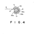
- the leading end portion of the magnetic tape 6 is affixed to the tape clamp portion 51 through a sheet member 8 by the clamp member 55 in order to enhance the coefficient of friction between the magnetic tape 6 and the tape clamp portion 51.
- This sheet member 8 has adhesive property and is stuck to one side of the magnetic tape 6.
- the sheet member 8 a flexible ribbon-like member, which has an adhesive layer on one side thereof, such as plastic sheet (polyester, etc.), form sheet, laminate film, laminate paper, etc., is used.
- the sheet member 8 is selected so that the coefficient of friction between the surface of the sheet member 8 and the leader pin 5 is higher than that between the surface of the magnetic tape 6 and the leader pin 5.
- the leader pin 5 is affixed to the leading end portion of the magnetic tape 6, by fitting the clamp member 55 on the tape clamp portion 51 of the leader pin 5 through the sheet member 8. Therefore, the friction coefficient between the sheet member 8 and the leader pin 5 becomes higher and the clamping force of the magnetic tape 6 is increased. The increased clamping force prevents the magnetic tape cartridge 1 from being disabled due to disengagement of the leader pin 5 from the magnetic tape 6. In addition, since the sheet member 8 with adhesive property is stuck to the magnetic tape 6 beforehand, the leader pin 5 can be easily attached to the leading end portion of the magnetic tape.
- the sheet member 8 may have no adhesive property, although the details are not shown. That is, this sheet member 8 is interposed between the magnetic tape 6 and the leader pin 5 without being stuck to the magnetic tape 6.
- the friction coefficient of the sheet member 8 is high as in the first embodiment. As a result, the clamping force of the magnetic tape 6 with respect to the leader pin 5 is increased and prevents disengagement between the magnetic tape 6 and the leader pin 5.
- the sheet member 8 is interposed between the magnetic tape 6 and the outer periphery of the leader pin 5
- this another sheet member may be interposed between the magnetic tape 6 and the inner periphery of the clamp member 55.
- clamp member 55 is not limited to a resin-molded product, but may be molded from other materials such as a thin metal plate, etc.
- a tape magnetic cartridge will hereinafter be described according to a second embodiment of the present invention with reference to Figs. 5 to 9.
- the magnetic tape cartridge 1 has a cartridge case 4, which is formed by fastening an upper case 2 and a lower case 3 together with small screws or the like. Within the cartridge case 4, a single reel 7 with magnetic tape 6 wound thereon is rotatably housed. The leading end portion of the magnetic tape 6 is affixed to a leader pin 5.
- the upper and lower cases 2 and 3 have side walls in which an opening 10 is formed to pull the magnetic tape 6 out of the cartridge case 4. Near this opening 10, there is provided a sliding door 11 that is opened and shut. The sliding door 11 is urged closed by elastic means (not shown) and slidable along a grooved door rail 12 (see Fig. 6).
- the upper and lower ends of the leader pin 5 affixed to the leading end of the magnetic tape 6 are held in upper and lower housing recesses 20, 20 formed near the opening 10, with the magnetic tape 6 completely wound on the reel 7.
- the upper and lower housing recesses 20, 20 are continuous to upper and lower insertion guide portions (guide surfaces) 21, 21, which are formed into lead-in structure toward the opening 10 so that the upper and lower ends of the leader pin 5 can be guided to the upper and lower housing recesses 20, 20.
- the leader pin 5 is held and pulled in by the drive unit of a recording-reproducing apparatus which uses the magnetic tape cartridge 1, so that the magnetic tape 6 is introduced into a tape traveling path within the recording-reproducing apparatus.
- a lock member 9 consisting of a plate spring is installed to detachably hold the upper and lower end portions of the leader pin 5 in the upper and lower housing recesses 20, 20.
- the leader pin 5 has a tape clamp shaft portion 5a at its central portion.
- the leading end portion of the magnetic tape 6 is wound on the tape clamp portion 5a and is clamped by fitting a C cross-section clamp member 5e onto the tape clamp portion 5a.
- the leader pin 5 also has upper and lower flange portions 5b, 5b at the upper and lower ends of the tape clamp portion 5a and further has narrow engagement portions 5c, 5c outside the upper and lower flange portions 5b, 5b.
- the engagement portions 5c, 5c extend axially and are engaged and held by the recording-reproducing apparatus.
- the leader pin 5 has locking portions 5d, 5d at the upper and lower ends thereof.
- This leader pin 5 is formed, for example, by cutting a shaft of metal such as stainless steel, etc., and the length of the tape clamp portion 5a equals the width of the magnetic tape 6.
- the clamp member 5e is molded from resin and has an axial length equivalent to the length of the tape clamp portion 5a of the leader pin 5.
- the clamp member 5e is formed into a C-shape in cross section and provided with a slit (Fig. 6) extending axially over the overall length.
- the clamp member 5e is elastically fitted on the outer periphery of the tape clamp portion 5a of the leader pin 5 through the axial slit.
- lock member 9 for holding the upper and lower end portions of the leader pin 5 in the upper and lower housing recesses 20, 20, and the structure for mounting said lock member 9.
- the lock member 9 has a mounting portion 9a in the form of a generally rectangular plate. With the upper case 2 and the lower case 3 stacked together, the mounting portion 9a is engaged and held by upper and lower lock-member installing portions 30, which are provided near the side walls 2b, 3b of the upper and lower cases 2, 3. Note that although only the lower lock-member installing portion 30 of the lower case 3 is shown, the upper lock-member installing portion 30 of the upper case 2 is symmetrical in shape with the lower lock-member installing portion 30.
- the lock member 9 also has a pair of elastic upper and lower arm portions 9b, 9b extending obliquely from the upper and lower end portions of the mounting portion 9a toward the leader pin 5.
- the upper and lower arm portions 9b, 9b have upper and lower pin-locking portions 9c, 9c at their outer ends, respectively.
- the elastic upper and lower pin-locking portions 9c, 9c abut the outer peripheries of the upper and lower locking portions 5d, 5d of the leader pin 5, respectively.
- Each pin-locking portion 9c is bent so that it projects toward the leader pin 5. If the leader pin 5 is inserted through the opening 10, the leader pin 5 is brought into contact with the outer inclined surface of the bent portion of each pin-locking portion 9c, and each elastic arm portion 9b is elastically deformed.
- the upper and lower locking portions 5d, 5d of the leader pin 5 are pressed against and held within the upper and lower housing recesses 20, 20 by the inner inclined surfaces of the bent portions of the upper and lower pin-locking portions 9c, 9c. Furthermore, the top and bottom edges of the mounting portion 9a of the lock member 9 are provided with upper and lower engagement recesses 9d, 9d.
- An interior angle ⁇ (see Fig. 7) that the mounting portion 9a forms with the bent elastic arm portion 9b is formed as an obtuse angle, preferably 135° or greater.
- the lock member 9 is as thin as 0.2 to 0.3 mm in order to obtain an appropriate leader-pin locking force.
- a lock member 50 shown in Fig. 13 is about 0.4 mm in thickness.
- the upper and lower elastic arm portions 9b, 9b may be provided so that they are connected at their proximal portions.
- the upper and lower lock-member installing portions 30 of the upper and lower cases 2, 3, which hold the lock member 9, are provided so that they hold the lock member 9 at positions away from the side walls 2b, 3b of the upper and lower cases 2, 3, preferably at positions 0.4 mm or more away from the side walls 2b, 3b from the standpoint of metal-mold strength.
- the lower lock-member installing portion 30 is equipped with a first support portion 31, and a second support portion 32 facing the first support portion 31.
- the upper lock-member installing portion (not shown) is formed the same as the lower lock-member installing portion 30.
- the first support portion 31 is formed integrally with the side wall 3b of the lower case 3 and projected in the form of a flat plate from the side wall 3b.
- the second support portion 32 is projected from the bottom wall 3a of the lower case 3.
- the amount that the first support member 31 projects from the side wall 3b is set to the dimension of the aforementioned hold position.
- the gap between the first support portion 31 and the second support portion 32 is formed to the thickness of the mounting portion 9a of the lock member 9 or greater.
- the mounting portion 9a of the lock member 9 is inserted into the gap between the first support portion 31 and the second support portion 32.
- the second support portion 32 is narrower in width than the first support portion 31 (see Fig. 9) but higher in height than the first support portion 31.
- the top surfaces of the first support portion 31 and the second support portion 32 are formed into inclined surfaces 31a, 32a (see Fig. 8) which become lower in height toward the gap therebetween.
- the lower end portion of the lock member 9 is guided to the gap between the first and second support portions 31 and 32 by the inclined surfaces 31a, 32a.
- a lower protrusion 33 (see Fig. 9) is formed so that it protrudes from the bottom surface 3a of the lower case 3.
- an upper protrusion (not shown) is formed in the upper case 2.
- the longitudinal width of the lower protrusion 33 is narrower than the width of the second support portion 32 of the lock-member installing portion 30.
- the width of the lower protrusion 33 equals the width of the engagement recess 9d in the lower edge of the mounting portion 9a of the lock member 9 so that the engagement recess 9d is fitted on the protrusion 33.
- the protrusion 33 has inclined guide surfaces 33a at the top edge thereof.
- the engagement recess 9d of the lock member 9 has inclined guide portions 9e so that the engagement recess 9d is easily fitted on the protrusion 33.
- the lower engagement recess 9d in the mounting portion 9a of the lock member 9 is easily fitted on the lower protrusion 33 between the first support portion 31 and the second support portion 32 of the spring type lower lock-member installing portion 30 of the lower case 3, while the lower engagement recess 9d is being guided by the inclined surfaces 31a, 32a, 33a and the guide portions 9e.
- the upper case 2 is stacked on the lower case 3 so that the upper lock-member installing portion 30 of the upper case 2 engages with the mounting portion 9a of the lock member 9. With the upper case 2 and the lower case 3 stacked together, they are assembled by tightening small screws.
- the upper case 2 and the lower case 3 are vertically positioned by the spring type lock-member installing portions 30 and longitudinally positioned by engagement between each protrusion 33 and each engagement recess 9d.
- the contact positions between the upper and lower pin-locking portions 9c, 9c of the lock member 9 and the upper and lower locking portions 5d, 5d of the leader pin 5 are assured.
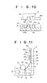
- first support portion 31 of the spring type lock-member installing portion 30 may be three separate support portions, as shown in Fig. 10. This structure is advantageous from the viewpoint of metal-mold strength.
- Figs. 11 and 12 illustrate a magnetic tape cartridge constructed according to an alternate embodiment of the present invention.
- the lock member 9 is formed in the same way as the aforementioned embodiments, but the spring type lock-member installing portion 30 differs in construction from the spring type lock-member installing portion 30 described above.
- the lower spring type lock-member installing portion 30 of the lower case 3, as in the case described above, has the first support portion 31, the second support portion 32, and the protrusion 33.
- the spring type lock-member installing portion 30 further has a tilt regulating portion 34 on the depth side of the first support portion 31.
- the tilt regulating portion 34 is used for holding the edge, opposite from the elastic arm portion 9b, of the lock member 9 in an erect posture.
- the upper spring type lock-member installing portion 30 of the upper case 2 similarly has the first support portion 31, the second support portion 32, and the protrusion 33, but does not have the tilt regulating portion 34.
- the tilt regulating portion 34 extends vertically in the form of a rib and is formed higher than the first support portion 31 and the second support portion 32.
- the interior surface of the tilt regulating portion 34 extends upward so that a tilt regulating gap equivalent to the thickness of the lock member 9 is formed between the interior surface and the first support portion 31, and holds the lock member 9 vertically.
- the tilt regulating portion 34 has an inclined guide face 34a at its top end so that the lock member 9 can be readily inserted into the tilt regulating gap.
- Figs. 13 and 14 illustrate a modification of the alternate embodiment illustrated in Figs. 11 and 12.
- the first support portion 31 of the lock-member installing portion 30 in Figs. 11 and 12 are divided into three separate support portions 31.
- the separate support portions 31 of the lower case 3 are disposed at positions away from the tilt regulating portion 34.
- This structure has an advantage of assuring metal-mold strength when molding the support portions 31.
- the lower case 3 is first placed with the top upward. Then, the lower end of the lock member 9 is inserted into the lock-member installing portion 30 of the lower case 3. Next, the upper case 2 is stacked on the lower case 3. However, conversely, with the upper case 2 upward, the lock member 9 may be installed and the lower case 3 stacked on the upper case 2. In this case the tilt regulating portion 34 needs to be provided in the upper case 2.
- the lower case 3 is placed with the top upward and then the upper case 2 is stacked on the lower case 3. After that, the cartridge case 4 is inverted up and down, and small screws are tightened.
- the upper case 2 has screw holes in the top surface, small screws can be tightened without inverting the cartridge case 4 up and down and the assembly step can be simplified. Therefore, it is preferable to provide screw holes according to an assembly step.
- a magnetic tape cartridge comprising: a single reel with magnetic tape wound thereon; a cartridge case for rotatably housing said single reel; a leader pin having a tape clamp portion on which said magnetic tape is wound; and a clamp member with a C cross section that has an axial slit; wherein said leader pin is affixed to a leading end of said magnetic tape by elastically fitting said clamp member onto said tape clamp portion of said leader pin; and wherein a sheet member for enhancing a coefficient of friction is interposed at least between said magnetic tape and said tape clamp portion.
- a magnetic tape cartridge comprising a single reel with magnetic tape wound thereon; a cartridge case, which comprises an upper case and a lower case, for rotatably housing said single reel; a leader pin affixed to a leading end of said magnetic tape to pull said magnetic tape out of said cartridge case; and a lock member, formed from a plate spring, for detachably locking and holding an upper end portion and a lower end portion of said leader pin; wherein said lock member comprises a mounting portion which is held by said upper and lower cases, and elastic arm portions extending from said mounting portion toward said leader pin and engageable with said upper and lower end portions of said leader pin; and wherein an inferior angle that said mounting portion forms with said elastic arm portion is an obtuse angle.
- said inferior angle that said mounting portion forms with said elastic arm portion is 135° or greater.
- a magnetic tape cartridge comprising a single reel with magnetic tape wound thereon; a cartridge case, which comprises an upper case and a lower case, for rotatably housing said single reel; a leader pin affixed to a leading end of said magnetic tape to pull said magnetic tape out of said cartridge case; a lock member, formed from a plate spring, for detachably locking and holding an upper end portion and a lower end portion of said leader pin; and upper and lower lock-member installing portions, provided in said upper and lower cases of said cartridge case, for holding said lock member; wherein said lock member comprises a mounting portion which is held by said upper and lower cases, and elastic arm portions extending from said mounting portion toward said leader pin and engageable with said upper and lower end portions of said leader pin; and wherein said upper and lower lock-member installing portions hold said lock member at positions 0.4 mm or greater away from side walls of said lower and upper cases.
- the mounting portion of said lock member has upper and lower engagement recesses at upper and lower edges thereof; said upper and lower lock-member installing portions have upper and lower protrusions; and said lock member is positioned and held by fitting said upper and lower protrusions into said upper and lower engagement recesses.
- one of said upper and lower lock-member installing portions has a tilt regulating portion for holding an edge, opposite from said elastic arm portions, of said mounting portion of said lock member in an erect posture.
- a magnetic tape cartridge comprising a single reel with magnetic tape wound thereon, a cartridge case for rotatably housing the single reel, a leader pin having a tape clamp portion on which the magnetic tape is wound, and a clamp member with a C cross section that has an axial slit.
- the leader pin is affixed to a leading end of the magnetic tape by elastically fitting the clamp member onto the tape clamp portion of the leader pin.
- a sheet member for enhancing a coefficient of friction is interposed at least between the magnetic tape and the tape clamp portion.
Landscapes
- Packaging Of Annular Or Rod-Shaped Articles, Wearing Apparel, Cassettes, Or The Like (AREA)
- Tape Measures (AREA)
- Magnetic Record Carriers (AREA)
Abstract
Description
- The present invention relates to a magnetic tape cartridge, in which a single tape reel with magnetic tape wound thereon is rotatably housed within a cartridge case, and in which a leader pin for pulling the magnetic tape out of the cartridge case is affixed to the leading end of the magnetic tape.
- In existing magnetic tape cartridges, which are being used as_storage media employed in external storage units for computers, etc., there is known a type where a single reel with magnetic tape wound thereon is rotatably housed within a cartridge case. This magnetic tape is employed to archive data for computers, etc. Since important information has been stored, the magnetic cartridge is constructed so that problems, such as tape jamming, etc., do not occur and that the magnetic tape is not pulled out of the cartridge case unexpectedly.
- Also, as shown in Figs. 1, 4, etc., of Japanese Unexamined Patent Publication No. 11(1999)-232838, a leader pin (tape pulling-out tool) is affixed to the leading end portion of the magnetic tape to pull the magnetic tape out of the cartridge case. This leader pin is held and pulled out by a hold member of a drive unit provided on the side of a recording-reproducing apparatus, whereby forward winding or reverse winding of the magnetic tape is performed. Uniting of the leader pin and the magnetic tape can be performed by winding the magnetic tape on the outer periphery of the tape clamp shaft portion of the leader pin and then elastically fitting a clamp member with a C cross section onto the tape clamp portion to clamp the leading end portion of the magnetic tape therebetween.
- In the structure in which the leader pin is affixed to the leading end of magnetic tape as described above, the coefficient of friction between the magnetic tape and the leader pin is low and therefore there is a possibility that because of insufficient clamping force, the leader pin will be disengaged from the magnetic tape.
- More specifically, in order to reduce the sliding friction between the magnetic tape and the magnetic head, there are cases where the addition of a lubricating agent to the magnetic layer of the magnetic tape, or the coating of a lubricating agent on the top surface of the magnetic tape, is performed so that the coefficient of friction is reduced. The bottom surface of the magnetic tape is also treated in the same manner. In that case, the coefficient of friction between the leader pin, formed from stainless steel, etc., and the magnetic tape varies with the type of the magnetic tape. When this coefficient of friction is low, there are cases where the clamping force of the magnetic tape with respect to the leader pin by the engagment of the clamp member onto the leader pin is reduced.
- The present invention has been made in view of the points mentioned above. Accordingly, it is a primary object of the present invention to provide a magnetic tape cartridge that is capable of enhancing the clamping force of the magnetic tape with respect to the leader pin to assure reliability.
- The aforementioned leader member is detachably held in the cartridge case by a lock member, called a shaft holding portion, which has an engaging function, as shown in Fig. 6 of the aforementioned Japanese Unexamined Patent Publication No. 11(1999)-232838. It is advantageous from the viewpoint of structural simplification to employ a spring member to hold the leader member.
- Therefore, if there is provided a lock member with integral upper and lower hold portions which abut the upper and lower ends of the leader pin, the assembly of the leader pin to the upper and lower cases of the magnetic tape cartridge will be enhanced. However, in forming the lock member by stamping and bending a plate spring, the manufacturing precision is reduced depending on the configuration of the lock member and there is a problem that the holding force of the lock member with respect to the leader pin will vary.
- For example, consider a lock member manufactured by pressing a plate spring such as that shown in Figs. 15 and 16. In Fig. 15, a
leader pin 5 affixed to the leading end ofmagnetic tape 6 is pulled in and out through anopening 10 formed in the side surfaces of an upper case (not shown) and alower case 3. Inside the opening 10, upper andlower housing recesses 20 are formed in the bottom surface of the upper case and the top surface of thelower case 3, and the upper and lower end portions of theleader pin 5 are held in thehousing recesses 20. Also, a taperedlower guide portion 21 is provided from the lower housing recess 20 toward theopening 10. Alock member 50, for detachably holding theleader pin 50 in thehousing recesses 20, is symmetrical in the vertical direction thereof and formed into a U-shape, as shown in Fig. 16. Thelock member 50 has amounting portion 50a, which is clamped between amounting boss 51 erected in the bottom surface of thelower case 3 and theside wall 3b of thelower case 3, along theside wall 3b. Thelock member 50 also has upper and lowerelastic arm portions mounting portion 50a toward theopening 10. Theelastic arm portions portions portions leader pin 5, respectively. Each leader-pin holding portion 50 is bent and has an outer inclined surface which is contacted and deformed by theleader pin 5 being inserted through the opening 10, and an inner inclined surface with which the leader pin is pressed against and held in the housing recess 20. - The
lock member 50 is bent into a deeply curved U-shape by pressing a plate spring, so it is difficult to accurately form an angle α (see Fig. 16) which themounting portion 50a forms with theelastic arm portion 50b. The amount of deformation in pressing and holding theleader pin 5 varies and therefore the holding force of thelock member 50 with respect to theleader pin 5 tends to vary. In addition, the deep U-shape pressing requires a plurality of press operations and increases the number of manufacturing steps. Since the deep U-shape pressing makes the length of theelastic arm portion 50b longer and thus increases the developed area, a large quantity of plate spring material is discarded after the stamping operation. Thus, the deeply U-shapedlock member 50 is disadvantageous in terms of cost. Furthermore, when a large number oflock members 50 are stored, they are stacked and engaged with one another, if eachlock member 50 has a deeply curved U-shape. Since it is difficult to separate them from each other, there is the problem that feeding them serially by a part feeder may become difficult. - On the other hand, in the mounting structure of the
lock member 50 in thecartridge case 4, in which themounting portion 50a of thelock member 50 is disposed along theside wall 3b of thelower case 3 and clamped between theside wall 3b and themounting boss 51, that part of the metal mold which molds the gap between themounting boss 51 and theside wall 3b will become very thin, if thelock member 50 is made thin in order to obtain proper leader-pin holding force. Because of this, there is a possibility that the thickness-reduced part of the metal mold will be damaged by pressure produced when resin is injected. It is also difficult to manufacture a metal mold having thin portions. Particularly, when themounting boss 51 is formed high, or long along theside wall 3b, the aforementioned phenomenon becomes conspicuous. - Furthermore, when the plate-
shaped lock member 50 is assembled into thecartridge case 4, depending on the locking structure there is a possibility that the upper case cannot be closed to thelower case 3. That is, when thelock member 50 is set to thelower case 3, and the upper case is stacked on thelower case 3, thelock member 50 tilts and cannot engage with themounting boss 51 of the upper case and abut the lower end of themounting boss 51, and therefore the upper case cannot be closed. Particularly, a space is required around theleader pin 5 so that a leader-pin pulling-out mechanism of a drive unit can enter through theopening 10 and hold theleader pin 5. The mountingboss 51 needs to be low in height so that it does not interfere with the leader-pin pulling-out mechanism, and the mounting boss also cannot be made high from the viewpoint of the metal-mold strength described above. Therefore, there is a possibility that problems associated with the aforementioned tilting will arise. - The present invention has been made in view of the points mentioned above. Accordingly, it is a secondary object of the present invention to provide a magnetic tape cartridge which is capable of holding the leader pin in a satisfactory manner by improving the manufacturing precision, mounting performance, etc., of the spring member which detachably holds the leader pin.
- To achieve the primary object of the present invention mentioned above, there is provided a first magnetic tape cartridge comprising (1) a single reel with magnetic tape wound thereon; (2) a cartridge case for rotatably housing the single reel; (3) a leader pin having a tape clamp portion on which the magnetic tape is wound; and (4) a clamp member with a C cross section that has an axial slit; wherein the leader pin is affixed to a leading end of the magnetic tape by elastically fitting the clamp member onto the tape clamp portion of the leader pin; and wherein a sheet member for enhancing a coefficient of friction is interposed at least between the magnetic tape and the tape clamp portion.
- The sheet member may be stuck to the magnetic tape. This case is preferable because the uniting operation of the magnetic tape and the leader pin is easily performed.
- In addition, the sheet member may be provided without being stuck to the magnetic tape. In this case, when the magnetic tape is repeatedly bent near the leader pin, as the position at which the magnetic tape is clamped varies, durability is enhanced.
- The sheet member refers to flexible ribbon-like members, such as plastic sheet (polyester, etc.), plastic film, foam sheet (elastomer, etc.), laminate film, laminate paper, etc. The sheet member is selected so that the coefficient of friction between the surface of the sheet member and the leader pin becomes higher than that between the surface of the magnetic tape and the leader pin.
- According to the first magnetic tape cartridge, the sheet member for enhancing a coefficient of friction is interposed at least between the magnetic tape and the tape clamp portion when the leader pin is affixed to the leading end portion of the magnetic tape by fitting the clamp member onto the leader pin. Therefore, even when the friction coefficient between the surface of the magnetic tape and the leader pin is low, the interposition of the sheet member enhances the friction coefficient between the sheet member and the leader pin and increases the clamping force of the magnetic tape with respect to the leader pin. As a result, disengagement of the leader pin from the magnetic tape can be prevented, whereby reliability can be assured.
- Furthermore, the interposition of the sheet member can reinforce the magnetic tape near the tape clamp portion of the leader pin when the leader pin is pulled out and in by a drive unit.
- To achieve the second object of the present invention mentioned above, there is provided a second magnetic tape cartridge comprising (1) a single reel with magnetic tape wound thereon; (2) a cartridge case, which comprises an upper case and a lower case, for rotatably housing the single reel; (3) a leader pin affixed to a leading end of the magnetic tape to pull the magnetic tape out of the cartridge case; and (4) a lock member, formed from a plate spring, for detachably locking and holding an upper end portion and a lower end portion of the leader pin; wherein the lock member comprises a mounting portion which is held by the upper and lower cases, and elastic arm portions extending from the mounting portion toward the leader pin and engageable with the upper and lower end portions of the leader pin; and wherein an interior angle that the mounting portion forms with the elastic arm portion is an obtuse angle.
- The interior angle that the mounting portion of the aforementioned lock member forms with the elastic arm portion of same is 135° or greater.
- Further, an alternate embodiment of this second magnetic tape cartridge is characterized by a lock member, formed from a plate spring, for detachably locking and holding an upper end portion and a lower end portion of the leader pin; upper and lower spring type lock-member installing portions, provided in the upper and lower cases of the cartridge case, for holding the lock member; wherein the lock member comprises a mounting portion which is held by the upper and lower cases, and elastic arm portions extending from the mounting portion toward the leader pin and engageable with the upper and lower end portions of the leader pin; and wherein the upper and lower spring type lock-member installing portions hold the lock member at positions away from side walls of the lower and upper cases to the inside. It is preferable from the viewpoint of metal-mold strength that the upper and lower lock-member installing portions be formed at positions 0. 4 mm or greater away from the side walls of the lower and upper cases.
- In the alternate embodiment of the second magnetic tape cartridge of the present invention described above, the mounting portion of the lock member has upper and lower engagement recesses at upper and lower edges thereof. The upper and lower lock-member installing portions have upper and lower protrusions. The lock member is positioned and held by fitting the upper and lower protrusions into the upper and lower engagement recesses.
- In addition, it is preferable that the lock-member installing portion be provided with inclined surfaces for guiding the lock member to the protrusion. It is also preferable that the lock member be provided with guide portions engageable with the inclined surfaces of the lock-member installing portion. By this structure, the engagement between the lock member and the lock-member installing portion can be facilitated.
- In the alternate embodiment of the second magnetic tape cartridge of the present invention, it is preferable that the upper and lower lock-member installing portions have a tilt regulating portion for holding an edge, opposite from the elastic arm portions, of the mounting portion of the lock member in an erect posture. By this structure, tilting of the lock member can be prevented.
- Note that when the lock member such as that described above is assembled into the cartridge case, the upper and lower cases of the cartridge case can be fastened together by tightening small screws inserted in holes formed in the upper case. In this case, the lock member is installed in the lower case. After the upper case is stacked on the lower case, they are assembled without inverting the cartridge case up and down. By this method, the assembly operation can be efficiently performed.
- According to the second magnetic tape cartridge of the present invention, an interior angle that the mounting portion of the lock member forms with the elastic arm portion of the lock member is an obtuse angle. Therefore, deep curve pressing is unnecessary, manufacturing precision is enhanced, and the amount of deformation in pressing and holding the leader pin becomes constant and therefore stable leader-pin locking force is obtained. In addition, the pressing operation becomes easy and manufacturing steps are simplified. The length of the elastic arm portion is short, so the developed area is reduced and costs are decreased. Furthermore, even if a large number of lock members are stored, they are less likely to engage each other and can be serially fed by a part feeder.
- According to an alternate embodiment of the second magnetic tape cartridge of the present invention, the upper and lower spring type lock-member installing portions hold the lock member at positions away from side walls of the lower and upper cases to the inside. Therefore, even if the lock member is made thin, that part of the metal mold which molds the wall surface of the cartridge case will not become thin and therefore the metal mold can be easily manufactured and damage to the metal mold can be prevented.
- If engagement recesses for fitting the protrusions of the spring type lock-member installing portion are provided in the upper and lower edges of the mounting portion of said lock member, longitudinal positioning of the lock member can be simultaneously performed and therefore the accuracy of position between the lock member and the leader pin can be enhanced.
- Furthermore, if the tilt regulating portion for holding the lock member in an erect posture is provided in said spring type lock-member installing portion, tilting of the lock member can be prevented, for example, when the lock member is installed in the lower case and the upper case is stacked on the lower case, while assuring a space for a leader-pin pulling-out mechanism of a drive unit. Thus, satisfactory assembly performance can be assured.
- If screw holes are formed in the top surface of the upper case so that assembly can be performed without inverting the cartridge case up and down, assembly performance is further enhanced.
- The present invention will be described in further detail with reference to the accompanying drawings wherein:
- FIG. 1 is an exploded perspective view of a magnetic tape cartridge according to a first embodiment of the present invention;
- FIG. 2 is a perspective view showing the state in which the clamp member of FIG. 1 is fitted on the leader pin of FIG. 1;
- FIG. 3 is a perspective view of the state before the leading end of the magnetic tape of FIG. 1 and the leader pin are joined together;
- FIG. 4 is a cross sectional view showing the state in which the magnetic tape and the leader pin are joined together;
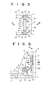
- FIG. 5 is a fragmentary front view of a magnetic tape cartridge according to a second embodiment of the present invention, the slide door having been opened to show the leader pin that is affixed to the leading end portion of magnetic tape;
- FIG. 6 is a sectional plan view taken substantially along line VI-VI of FIG. 5;
- FIG. 7 is a perspective view of the lock member of the magnetic tape cartridge of FIG. 5;
- FIG. 8 is a sectional view of a lock-member installing portion taken substantially along line VIII-VIII of FIG. 6;
- FIG. 9 is a sectional view of the lock-member installing portion taken substantially along line IX-IX of FIG. 6;
- FIG. 10 is a sectional view of a modification of the lock-member installing portion of FIG. 9;
- FIG. 11 is a fragmentary front view of a magnetic tape cartridge according to an alternate embodiment of the present invention, the upper case of the cartridge having been removed to show components near the opening of the cartridge;
- FIG. 12 is a fragmentary perspective view showing the state in which the lock member of FIG. 11 is installed;
- FIG. 13 is a fragmentary plan view of a modification of the magnetic tape cartridge shown in FIG. 11, the upper case of the cartridge having been removed to show components near the opening of the cartridge;
- FIG. 14 is a fragmentary perspective view showing the state in which the lock member of FIG. 13 is installed;
- FIG. 15 is a fragmentary plan view of a conventional magnetic tape cartridge, the upper case of the cartridge having been removed to show components near the opening of the cartridge; and
- FIG. 16 is a perspective view showing the lock member of FIG. 15.
- Referring now in greater detail to the drawings and initially to Fig. 1, there is shown an exploded view of a magnetic tape cartridge 1 in accordance with a first embodiment of the present invention. The magnetic tape cartridge 1 has a
cartridge case 4, which is formed by fastening anupper case 2 and alower case 3 together with small screws or the like. Within thecartridge case 4, asingle reel 7 withmagnetic tape 6 wound thereon is rotatably housed. The leading end portion of themagnetic tape 6 is affixed to aleader pin 5. The upper andlower cases opening 10 is formed to pull themagnetic tape 6 out of thecartridge case 4. Near thisopening 10, there is provided aslide door 11 that is opened and shut. Theslide door 11 is urged closed by elastic means (not shown). - During non-use of the magnetic tape cartridge 1 , the upper and lower ends of the
leader pin 5 affixed to the leading end of themagnetic tape 6 are held in upper andlower housing recesses opening 10, with themagnetic tape 6 completely wound on thereel 7. - The
leader pin 5 is held and pulled in by a drive unit of a recording-reproducing apparatus, which uses the magnetic tape cartridge 1, so that themagnetic tape 6 is introduced into a tape traveling path within the recording-reproducing apparatus. Aclamp member 55 to be described below(see Figs. 2 and 3) is fitted on theleader pin 5 to clamp themagnetic tape 6 therebetween. Also, alock member 9 consisting of a plate spring is installed to detachably hold the upper and lower end portions of theleader pin 5 in the upper andlower housing recesses - In Fig. 1, the upper and
lower cases side walls top wall 2a and thebottom wall 3a. The upper andlower cases inner walls 3c (arc-shaped inner walls for theupper case 2 are not shown) along the outer periphery of thereel 7. Thelower case 3 has fourboss portions 3d (aboss portion 3d near theopening 10 is hidden behind the slide door 11) between theside walls 3b and theinner walls 3c. Similarly, theupper case 2 has four boss portions (not shown). Thelower case 3 is fastened to theupper case 2 by abutting theboss portions 3d of thelower case 3 with the boss portions of theupper case 2 and then tightening small screws through the bottom surface of thelower case 3. Note that tightening of the small screws with respect to theboss portions 3d may be performed through the top surface of theupper case 2, as described later. - The center portion of the
lower case 3 also has acenter hole 3e so that thereel 7 can be driven by a driving shaft of the aforementioned drive unit. Awrite protector member 13 is slidably disposed in the rear end portion of thecartridge case 4. The center portion of thereel 7 is provided with arotation regulating mechanism 15 for restricting rotation of thereel 7 during non-use of the magnetic tape cartridge 1. - In addition to the above, although not shown, the
reel 7 includes a reel plate mounted on the central portion of the bottom surface thereof, the reel plate being used for attracting and holding magnetic type rotation means. The radially outer portion of the bottom surface of thereel 7 has a reel gear that meshes with the driving gear of the rotation means. If the reel gear and the driving gear mesh with each other, therotation regulating mechanism 15 performs an unlocking operation and frees thereel 7 to rotate. - As illustrated in Figs. 2 and 3, the
leader pin 5 has a tapeclamp shaft portion 51 at its central portion. The leading end portion of themagnetic tape 6 is wound on thetape clamp portion 51 and is clamped by fitting a Ccross-section clamp member 55 onto thetape clamp portion 51. Theleader pin 5 also has upper andlower flange portions tape clamp portion 51 and further hasnarrow engagement portions lower flange portions engagement portions leader pin 5 has lockingportions - The
leader pin 5 is formed, for example, by cutting a shaft of metal such as stainless steel, etc., and the length of thetape clamp portion 51 is set so that it equals the width of themagnetic tape 6. - The
clamp member 55 is molded from resin and has an axial length equivalent to the length of thetape clamp portion 51 of theleader pin 5. Theclamp member 55 is formed into a C-shape in cross section and provided with aslit 55a extending axially over the overall length. Theclamp member 55 consists of anouter periphery 55b, aninner periphery 55c, and end faces 55d. The width of theslit 55a in theclamp member 55 is narrower than the outside diameter of thetape clamp portion 51 of theleader pin 5 so that theclamp member 55 can be elastically fitted on theleader pin 5. - As illustrated in Figs. 3 and 4, the leading end portion of the
magnetic tape 6 is affixed to thetape clamp portion 51 through asheet member 8 by theclamp member 55 in order to enhance the coefficient of friction between themagnetic tape 6 and thetape clamp portion 51. Thissheet member 8 has adhesive property and is stuck to one side of themagnetic tape 6. With theclamp member 55 fitted on thetape clamp portion 51 of theleader pin 5, the surface of thesheet member 8 contacts the surface of thetape clamp portion 51 of theleader pin 5, and the exterior surface of themagnetic tape 6 contacts theinner periphery 55c of theclamp member 55. - As the
sheet member 8, a flexible ribbon-like member, which has an adhesive layer on one side thereof, such as plastic sheet (polyester, etc.), form sheet, laminate film, laminate paper, etc., is used. Thesheet member 8 is selected so that the coefficient of friction between the surface of thesheet member 8 and theleader pin 5 is higher than that between the surface of themagnetic tape 6 and theleader pin 5. - According to the first embodiment, the
leader pin 5 is affixed to the leading end portion of themagnetic tape 6, by fitting theclamp member 55 on thetape clamp portion 51 of theleader pin 5 through thesheet member 8. Therefore, the friction coefficient between thesheet member 8 and theleader pin 5 becomes higher and the clamping force of themagnetic tape 6 is increased. The increased clamping force prevents the magnetic tape cartridge 1 from being disabled due to disengagement of theleader pin 5 from themagnetic tape 6. In addition, since thesheet member 8 with adhesive property is stuck to themagnetic tape 6 beforehand, theleader pin 5 can be easily attached to the leading end portion of the magnetic tape. - As a modification of the first embodiment, the
sheet member 8 may have no adhesive property, although the details are not shown. That is, thissheet member 8 is interposed between themagnetic tape 6 and theleader pin 5 without being stuck to themagnetic tape 6. The friction coefficient of thesheet member 8 is high as in the first embodiment. As a result, the clamping force of themagnetic tape 6 with respect to theleader pin 5 is increased and prevents disengagement between themagnetic tape 6 and theleader pin 5. - There are cases where a hold block of the drive unit holding the
leader pin 5, as it is, is fitted on a winding reel of the drive unit and driven to rotate. If, in that case, themagnetic tape 6 is repeatedly bent near theleader pin 5 at an acute angle, themagnetic tape 6 will be degraded at the bent portion and a problem of durability will arise. However, in the modification of the first embodiment, the position at which themagnetic tape 6 clamps theleader pin 5 will shift slightly due to thesheet 8 being disposed in a non-adhesive manner and therefore a position at which themagnetic tape 6 is bent will change. Thus, themagnetic tape 6 is prevented from being bent at the same position and is enhanced in durability. - While, in the first embodiment, the
sheet member 8 is interposed between themagnetic tape 6 and the outer periphery of theleader pin 5, in addition to this another sheet member may be interposed between themagnetic tape 6 and the inner periphery of theclamp member 55. - In addition, the
clamp member 55 is not limited to a resin-molded product, but may be molded from other materials such as a thin metal plate, etc. - A tape magnetic cartridge will hereinafter be described according to a second embodiment of the present invention with reference to Figs. 5 to 9.
- The magnetic tape cartridge 1 has a
cartridge case 4, which is formed by fastening anupper case 2 and alower case 3 together with small screws or the like. Within thecartridge case 4, asingle reel 7 withmagnetic tape 6 wound thereon is rotatably housed. The leading end portion of themagnetic tape 6 is affixed to aleader pin 5. The upper andlower cases opening 10 is formed to pull themagnetic tape 6 out of thecartridge case 4. Near thisopening 10, there is provided a slidingdoor 11 that is opened and shut. The slidingdoor 11 is urged closed by elastic means (not shown) and slidable along a grooved door rail 12 (see Fig. 6). - During non-use of the magnetic tape cartridge 1, the upper and lower ends of the
leader pin 5 affixed to the leading end of themagnetic tape 6 are held in upper andlower housing recesses opening 10, with themagnetic tape 6 completely wound on thereel 7. The upper andlower housing recesses opening 10 so that the upper and lower ends of theleader pin 5 can be guided to the upper andlower housing recesses - The
leader pin 5 is held and pulled in by the drive unit of a recording-reproducing apparatus which uses the magnetic tape cartridge 1, so that themagnetic tape 6 is introduced into a tape traveling path within the recording-reproducing apparatus. Alock member 9 consisting of a plate spring is installed to detachably hold the upper and lower end portions of theleader pin 5 in the upper andlower housing recesses - As illustrated in Figs. 5 and 6, the
leader pin 5 has a tapeclamp shaft portion 5a at its central portion. The leading end portion of themagnetic tape 6 is wound on thetape clamp portion 5a and is clamped by fitting a Ccross-section clamp member 5e onto thetape clamp portion 5a. Theleader pin 5 also has upper andlower flange portions tape clamp portion 5a and further hasnarrow engagement portions lower flange portions engagement portions leader pin 5 has lockingportions leader pin 5 is formed, for example, by cutting a shaft of metal such as stainless steel, etc., and the length of thetape clamp portion 5a equals the width of themagnetic tape 6. - The
clamp member 5e is molded from resin and has an axial length equivalent to the length of thetape clamp portion 5a of theleader pin 5. Theclamp member 5e is formed into a C-shape in cross section and provided with a slit (Fig. 6) extending axially over the overall length. Theclamp member 5e is elastically fitted on the outer periphery of thetape clamp portion 5a of theleader pin 5 through the axial slit. - Next, a description will be given of the
lock member 9 for holding the upper and lower end portions of theleader pin 5 in the upper andlower housing recesses lock member 9. - The
lock member 9 has a mountingportion 9a in the form of a generally rectangular plate. With theupper case 2 and thelower case 3 stacked together, the mountingportion 9a is engaged and held by upper and lower lock-member installing portions 30, which are provided near theside walls lower cases member installing portion 30 of thelower case 3 is shown, the upper lock-member installing portion 30 of theupper case 2 is symmetrical in shape with the lower lock-member installing portion 30. Thelock member 9 also has a pair of elastic upper andlower arm portions portion 9a toward theleader pin 5. The upper andlower arm portions portions portions lower locking portions leader pin 5, respectively. Each pin-lockingportion 9c is bent so that it projects toward theleader pin 5. If theleader pin 5 is inserted through theopening 10, theleader pin 5 is brought into contact with the outer inclined surface of the bent portion of each pin-lockingportion 9c, and eachelastic arm portion 9b is elastically deformed. As a result, the upper andlower locking portions leader pin 5 are pressed against and held within the upper andlower housing recesses portions portion 9a of thelock member 9 are provided with upper andlower engagement recesses - An interior angle β (see Fig. 7) that the mounting
portion 9a forms with the bentelastic arm portion 9b is formed as an obtuse angle, preferably 135° or greater. In relation to the length of theelastic arm portion 9b, etc. , thelock member 9 is as thin as 0.2 to 0.3 mm in order to obtain an appropriate leader-pin locking force. Note that alock member 50 shown in Fig. 13 is about 0.4 mm in thickness. Also, the upper and lowerelastic arm portions - The upper and lower lock-
member installing portions 30 of the upper andlower cases lock member 9, are provided so that they hold thelock member 9 at positions away from theside walls lower cases side walls - The lower lock-
member installing portion 30 is equipped with afirst support portion 31, and asecond support portion 32 facing thefirst support portion 31. Note that the upper lock-member installing portion (not shown) is formed the same as the lower lock-member installing portion 30. Thefirst support portion 31 is formed integrally with theside wall 3b of thelower case 3 and projected in the form of a flat plate from theside wall 3b. Thesecond support portion 32 is projected from thebottom wall 3a of thelower case 3. The amount that thefirst support member 31 projects from theside wall 3b is set to the dimension of the aforementioned hold position. The gap between thefirst support portion 31 and thesecond support portion 32 is formed to the thickness of the mountingportion 9a of thelock member 9 or greater. The mountingportion 9a of thelock member 9 is inserted into the gap between thefirst support portion 31 and thesecond support portion 32. - The
second support portion 32 is narrower in width than the first support portion 31 (see Fig. 9) but higher in height than thefirst support portion 31. The top surfaces of thefirst support portion 31 and thesecond support portion 32 are formed intoinclined surfaces lock member 9 is guided to the gap between the first andsecond support portions inclined surfaces - Between the
first support portion 31 and thesecond support portion 32, a lower protrusion 33 (see Fig. 9) is formed so that it protrudes from thebottom surface 3a of thelower case 3. Similarly, an upper protrusion (not shown) is formed in theupper case 2. The longitudinal width of thelower protrusion 33 is narrower than the width of thesecond support portion 32 of the lock-member installing portion 30. Across theprotrusion 33, there are formed front and rear gaps into which thelock member 9 is inserted. The width of thelower protrusion 33 equals the width of theengagement recess 9d in the lower edge of the mountingportion 9a of thelock member 9 so that theengagement recess 9d is fitted on theprotrusion 33. Furthermore, theprotrusion 33 has inclined guide surfaces 33a at the top edge thereof. Similarly, theengagement recess 9d of thelock member 9 has inclinedguide portions 9e so that theengagement recess 9d is easily fitted on theprotrusion 33. - With the mounting structure mentioned above, as shown in Figs. 8 and 9, the
lower engagement recess 9d in the mountingportion 9a of thelock member 9 is easily fitted on thelower protrusion 33 between thefirst support portion 31 and thesecond support portion 32 of the spring type lower lock-member installing portion 30 of thelower case 3, while thelower engagement recess 9d is being guided by theinclined surfaces guide portions 9e. After other components, such as thereel 7, etc., are assembled within thelower case 3, theupper case 2 is stacked on thelower case 3 so that the upper lock-member installing portion 30 of theupper case 2 engages with the mountingportion 9a of thelock member 9. With theupper case 2 and thelower case 3 stacked together, they are assembled by tightening small screws. - In assembling the
upper case 2 and thelower case 3, theupper case 2 and thelower case 3 are vertically positioned by the spring type lock-member installing portions 30 and longitudinally positioned by engagement between eachprotrusion 33 and eachengagement recess 9d. As a result, the contact positions between the upper and lower pin-lockingportions lock member 9 and the upper andlower locking portions leader pin 5 are assured. - Note that the
first support portion 31 of the spring type lock-member installing portion 30 may be three separate support portions, as shown in Fig. 10. This structure is advantageous from the viewpoint of metal-mold strength. - Figs. 11 and 12 illustrate a magnetic tape cartridge constructed according to an alternate embodiment of the present invention. The
lock member 9 is formed in the same way as the aforementioned embodiments, but the spring type lock-member installing portion 30 differs in construction from the spring type lock-member installing portion 30 described above. - The lower spring type lock-
member installing portion 30 of thelower case 3, as in the case described above, has thefirst support portion 31, thesecond support portion 32, and theprotrusion 33. The spring type lock-member installing portion 30 further has atilt regulating portion 34 on the depth side of thefirst support portion 31. Thetilt regulating portion 34 is used for holding the edge, opposite from theelastic arm portion 9b, of thelock member 9 in an erect posture. The upper spring type lock-member installing portion 30 of theupper case 2 similarly has thefirst support portion 31, thesecond support portion 32, and theprotrusion 33, but does not have thetilt regulating portion 34. - The
tilt regulating portion 34 extends vertically in the form of a rib and is formed higher than thefirst support portion 31 and thesecond support portion 32. The interior surface of thetilt regulating portion 34 extends upward so that a tilt regulating gap equivalent to the thickness of thelock member 9 is formed between the interior surface and thefirst support portion 31, and holds thelock member 9 vertically. Thetilt regulating portion 34 has aninclined guide face 34a at its top end so that thelock member 9 can be readily inserted into the tilt regulating gap. - In this alternate embodiment, when the
lock member 9 is installed in the lock-member installing portion 30 of thelower case 3, tilting of thelock member 9, particularly tilting toward the inside of the case, is regulated by thetilt regulating portion 34. Therefore, the engagement of thelock member 9 with the lock-member installing portion 30 of theupper case 2 in stacking theupper case 2 on thelower case 3 is performed with reliability, and the workability is enhanced. - Figs. 13 and 14 illustrate a modification of the alternate embodiment illustrated in Figs. 11 and 12. The
first support portion 31 of the lock-member installing portion 30 in Figs. 11 and 12 are divided into threeseparate support portions 31. Particularly, theseparate support portions 31 of thelower case 3 are disposed at positions away from thetilt regulating portion 34. This structure has an advantage of assuring metal-mold strength when molding thesupport portions 31. - In the aforementioned embodiments, the
lower case 3 is first placed with the top upward. Then, the lower end of thelock member 9 is inserted into the lock-member installing portion 30 of thelower case 3. Next, theupper case 2 is stacked on thelower case 3. However, conversely, with theupper case 2 upward, thelock member 9 may be installed and thelower case 3 stacked on theupper case 2. In this case thetilt regulating portion 34 needs to be provided in theupper case 2. - Also, in the case where the
lock member 9 is installed in thelower case 3 having screw holes in the bottom surface thereof, thelower case 3 is placed with the top upward and then theupper case 2 is stacked on thelower case 3. After that, thecartridge case 4 is inverted up and down, and small screws are tightened. However, if theupper case 2 has screw holes in the top surface, small screws can be tightened without inverting thecartridge case 4 up and down and the assembly step can be simplified. Therefore, it is preferable to provide screw holes according to an assembly step. - While the present invention has been described with reference to the preferred embodiments thereof, the invention is not to be limited to the details given herein, but may be modified within the scope of the invention hereinafter claimed.
- The description above discloses (amongst others) a magnetic tape cartridge comprising: a single reel with magnetic tape wound thereon; a cartridge case for rotatably housing said single reel; a leader pin having a tape clamp portion on which said magnetic tape is wound; and a clamp member with a C cross section that has an axial slit; wherein said leader pin is affixed to a leading end of said magnetic tape by elastically fitting said clamp member onto said tape clamp portion of said leader pin; and wherein a sheet member for enhancing a coefficient of friction is interposed at least between said magnetic tape and said tape clamp portion.
- It further discloses a magnetic tape cartridge comprising a single reel with magnetic tape wound thereon; a cartridge case, which comprises an upper case and a lower case, for rotatably housing said single reel; a leader pin affixed to a leading end of said magnetic tape to pull said magnetic tape out of said cartridge case; and a lock member, formed from a plate spring, for detachably locking and holding an upper end portion and a lower end portion of said leader pin; wherein said lock member comprises a mounting portion which is held by said upper and lower cases, and elastic arm portions extending from said mounting portion toward said leader pin and engageable with said upper and lower end portions of said leader pin; and wherein an inferior angle that said mounting portion forms with said elastic arm portion is an obtuse angle.
- Therein, it is preferable if said inferior angle that said mounting portion forms with said elastic arm portion is 135° or greater.
- The description also discloses a magnetic tape cartridge comprising a single reel with magnetic tape wound thereon; a cartridge case, which comprises an upper case and a lower case, for rotatably housing said single reel; a leader pin affixed to a leading end of said magnetic tape to pull said magnetic tape out of said cartridge case; a lock member, formed from a plate spring, for detachably locking and holding an upper end portion and a lower end portion of said leader pin; and upper and lower lock-member installing portions, provided in said upper and lower cases of said cartridge case, for holding said lock member; wherein said lock member comprises a mounting portion which is held by said upper and lower cases, and elastic arm portions extending from said mounting portion toward said leader pin and engageable with said upper and lower end portions of said leader pin; and wherein said upper and lower lock-member installing portions hold said lock member at positions 0.4 mm or greater away from side walls of said lower and upper cases.
- Therein, it is preferable if the mounting portion of said lock member has upper and lower engagement recesses at upper and lower edges thereof; said upper and lower lock-member installing portions have upper and lower protrusions; and said lock member is positioned and held by fitting said upper and lower protrusions into said upper and lower engagement recesses.
- It is also preferable if one of said upper and lower lock-member installing portions has a tilt regulating portion for holding an edge, opposite from said elastic arm portions, of said mounting portion of said lock member in an erect posture.
- In short, there is disclosed a magnetic tape cartridge comprising a single reel with magnetic tape wound thereon, a cartridge case for rotatably housing the single reel, a leader pin having a tape clamp portion on which the magnetic tape is wound, and a clamp member with a C cross section that has an axial slit. The leader pin is affixed to a leading end of the magnetic tape by elastically fitting the clamp member onto the tape clamp portion of the leader pin. A sheet member for enhancing a coefficient of friction is interposed at least between the magnetic tape and the tape clamp portion.
Claims (2)
- A magnetic tape cartridge comprising:a single reel with magnetic tape wound thereon;a cartridge case, which comprises an upper case and a lower case, for rotatably housing said single reel;a leader pin affixed to a leading end of said magnetic tape to pull said magnetic tape out of said cartridge case; anda lock member, formed from a plate spring, for detachably locking and holding an upper end portion and a lower end portion of said leader pin;wherein said lock member comprises a mounting portion which is held by said upper and lower cases, said elastic arm portions extending from said mounting portion toward said leader pin and engageable with said upper and lower end portions of said leader pin; and
wherein an interior angle that said mounting portion forms with said elastic arm portion is an obtuse angle. - The magnetic tape cartridge according to claim 1, wherein said interior angle that said mounting portion forms with said elastic arm portion is 135° or greater.
Applications Claiming Priority (3)
| Application Number | Priority Date | Filing Date | Title |
|---|---|---|---|
| JP3866399 | 1999-02-17 | ||
| JP03866399A JP3707948B2 (en) | 1999-02-17 | 1999-02-17 | Magnetic tape cartridge |
| EP00902899A EP1162619B1 (en) | 1999-02-17 | 2000-02-10 | Magnetic tape cartridge |
Related Parent Applications (2)
| Application Number | Title | Priority Date | Filing Date |
|---|---|---|---|
| EP00902899.4 Division | 2000-02-10 | ||
| EP00902899A Division EP1162619B1 (en) | 1999-02-17 | 2000-02-10 | Magnetic tape cartridge |
Publications (2)
| Publication Number | Publication Date |
|---|---|
| EP1414039A1 true EP1414039A1 (en) | 2004-04-28 |
| EP1414039B1 EP1414039B1 (en) | 2006-04-26 |
Family
ID=12531521
Family Applications (2)
| Application Number | Title | Priority Date | Filing Date |
|---|---|---|---|
| EP03028750A Expired - Lifetime EP1414039B1 (en) | 1999-02-17 | 2000-02-10 | Magnetic tape cartridge |
| EP00902899A Expired - Lifetime EP1162619B1 (en) | 1999-02-17 | 2000-02-10 | Magnetic tape cartridge |
Family Applications After (1)
| Application Number | Title | Priority Date | Filing Date |
|---|---|---|---|
| EP00902899A Expired - Lifetime EP1162619B1 (en) | 1999-02-17 | 2000-02-10 | Magnetic tape cartridge |
Country Status (7)
| Country | Link |
|---|---|
| US (3) | US6663036B1 (en) |
| EP (2) | EP1414039B1 (en) |
| JP (1) | JP3707948B2 (en) |
| KR (1) | KR100411976B1 (en) |
| CN (3) | CN1273988C (en) |
| DE (2) | DE60016576T2 (en) |
| WO (1) | WO2000049615A1 (en) |
Families Citing this family (18)
| Publication number | Priority date | Publication date | Assignee | Title |
|---|---|---|---|---|
| DE60128969T2 (en) * | 2000-04-05 | 2007-10-18 | Fujifilm Corp. | Magnetic tape cartridge |
| US6796520B2 (en) * | 2001-01-30 | 2004-09-28 | Fuji Photo Film Co., Ltd. | Magnetic tape cartridge |
| JP2003036627A (en) * | 2001-07-23 | 2003-02-07 | Fuji Photo Film Co Ltd | Recording tape cartridge |
| JP4009081B2 (en) | 2001-10-15 | 2007-11-14 | 富士フイルム株式会社 | Recording tape cartridge |
| JP3718154B2 (en) | 2001-10-15 | 2005-11-16 | 富士写真フイルム株式会社 | Recording tape cartridge |
| JP3710405B2 (en) | 2001-10-15 | 2005-10-26 | 富士写真フイルム株式会社 | Recording tape cartridge |
| JP3710411B2 (en) | 2001-11-20 | 2005-10-26 | 富士写真フイルム株式会社 | Recording tape cartridge |
| JP3710414B2 (en) | 2001-11-20 | 2005-10-26 | 富士写真フイルム株式会社 | Recording tape cartridge |
| JP4179804B2 (en) * | 2002-05-29 | 2008-11-12 | 富士フイルム株式会社 | Recording tape cartridge |
| JP2005302169A (en) * | 2004-04-13 | 2005-10-27 | Fuji Photo Film Co Ltd | Leader tape and magnetic tape cartridge using the same |
| JP2006209887A (en) * | 2005-01-28 | 2006-08-10 | Fuji Photo Film Co Ltd | Recording tape cartridge |
| JP4680208B2 (en) * | 2007-01-26 | 2011-05-11 | 富士フイルム株式会社 | Recording tape cartridge |
| JP4602368B2 (en) * | 2007-03-02 | 2010-12-22 | 富士フイルム株式会社 | Recording tape cartridge |
| US7815140B2 (en) * | 2008-03-11 | 2010-10-19 | Fujifilm Corporation | Recording tape cartridge |
| CN102045987A (en) * | 2009-10-09 | 2011-05-04 | 鸿富锦精密工业(深圳)有限公司 | Wind scooper |
| US20110229238A1 (en) * | 2010-03-18 | 2011-09-22 | Seiko Epson Corporation | Tape Cartridge |
| JP6094519B2 (en) * | 2014-03-24 | 2017-03-15 | ソニー株式会社 | Magnetic tape cartridge |
| WO2017014307A1 (en) * | 2015-07-23 | 2017-01-26 | 富士フイルム株式会社 | Laminate |
Citations (4)
| Publication number | Priority date | Publication date | Assignee | Title |
|---|---|---|---|---|
| US4694557A (en) * | 1986-03-25 | 1987-09-22 | Shape Inc. | Leader tape staking rod and related method of assembly |
| US5465187A (en) * | 1992-09-25 | 1995-11-07 | Storage Technology Corporation | Magnetic tape cartridge having leader block retainer mechanism |
| EP0926675A1 (en) * | 1997-12-24 | 1999-06-30 | Fuji Photo Film Co., Ltd. | Magnetic tape cartridge |
| WO2000031739A1 (en) * | 1998-11-20 | 2000-06-02 | Fuji Photo Film Co., Ltd. | Magnetic tape cartridge |
Family Cites Families (5)
| Publication number | Priority date | Publication date | Assignee | Title |
|---|---|---|---|---|
| JP3614633B2 (en) * | 1997-12-22 | 2005-01-26 | 富士写真フイルム株式会社 | Magnetic tape cartridge |
| JPH11232838A (en) | 1998-02-16 | 1999-08-27 | Matsushita Electric Ind Co Ltd | Optical disk, optical disk recording device, and optical disk reader |
| JP3979477B2 (en) * | 1998-02-18 | 2007-09-19 | 日立マクセル株式会社 | Single reel type magnetic tape cartridge |
| US6003802A (en) * | 1998-04-03 | 1999-12-21 | Seagate Technology, Inc. | Tape leader pin assembly and method for making the same |
| DE60128969T2 (en) * | 2000-04-05 | 2007-10-18 | Fujifilm Corp. | Magnetic tape cartridge |
-
1999
- 1999-02-17 JP JP03866399A patent/JP3707948B2/en not_active Expired - Fee Related
-
2000
- 2000-02-10 US US09/913,733 patent/US6663036B1/en not_active Expired - Lifetime
- 2000-02-10 EP EP03028750A patent/EP1414039B1/en not_active Expired - Lifetime
- 2000-02-10 WO PCT/JP2000/000738 patent/WO2000049615A1/en not_active Ceased
- 2000-02-10 CN CNB2003101232385A patent/CN1273988C/en not_active Expired - Fee Related
- 2000-02-10 KR KR10-2001-7010274A patent/KR100411976B1/en not_active Expired - Fee Related
- 2000-02-10 DE DE60016576T patent/DE60016576T2/en not_active Expired - Lifetime
- 2000-02-10 CN CNB008039003A patent/CN1163898C/en not_active Expired - Fee Related
- 2000-02-10 EP EP00902899A patent/EP1162619B1/en not_active Expired - Lifetime
- 2000-02-10 CN CNB200310123239XA patent/CN1261943C/en not_active Expired - Fee Related
- 2000-02-10 DE DE60027612T patent/DE60027612T2/en not_active Expired - Lifetime
-
2003
- 2003-08-05 US US10/633,670 patent/US7014138B2/en not_active Expired - Lifetime
- 2003-08-05 US US10/633,703 patent/US6981669B2/en not_active Expired - Fee Related
Patent Citations (5)
| Publication number | Priority date | Publication date | Assignee | Title |
|---|---|---|---|---|
| US4694557A (en) * | 1986-03-25 | 1987-09-22 | Shape Inc. | Leader tape staking rod and related method of assembly |
| US5465187A (en) * | 1992-09-25 | 1995-11-07 | Storage Technology Corporation | Magnetic tape cartridge having leader block retainer mechanism |
| EP0926675A1 (en) * | 1997-12-24 | 1999-06-30 | Fuji Photo Film Co., Ltd. | Magnetic tape cartridge |
| WO2000031739A1 (en) * | 1998-11-20 | 2000-06-02 | Fuji Photo Film Co., Ltd. | Magnetic tape cartridge |
| EP1150296A1 (en) * | 1998-11-20 | 2001-10-31 | Fuji Photo Film Co., Ltd. | Magnetic tape cartridge |
Also Published As
| Publication number | Publication date |
|---|---|
| EP1414039B1 (en) | 2006-04-26 |
| US6981669B2 (en) | 2006-01-03 |
| CN1340195A (en) | 2002-03-13 |
| DE60027612D1 (en) | 2006-06-01 |
| KR20010102114A (en) | 2001-11-15 |
| US7014138B2 (en) | 2006-03-21 |
| CN1261943C (en) | 2006-06-28 |
| EP1162619B1 (en) | 2004-12-08 |
| US6663036B1 (en) | 2003-12-16 |
| EP1162619A1 (en) | 2001-12-12 |
| CN1516181A (en) | 2004-07-28 |
| DE60016576D1 (en) | 2005-01-13 |
| CN1516180A (en) | 2004-07-28 |
| JP3707948B2 (en) | 2005-10-19 |
| CN1163898C (en) | 2004-08-25 |
| JP2000243056A (en) | 2000-09-08 |
| EP1162619A4 (en) | 2003-05-21 |
| CN1273988C (en) | 2006-09-06 |
| DE60027612T2 (en) | 2006-09-07 |
| KR100411976B1 (en) | 2003-12-24 |
| DE60016576T2 (en) | 2005-04-28 |
| US20040021026A1 (en) | 2004-02-05 |
| US20040026553A1 (en) | 2004-02-12 |
| WO2000049615A1 (en) | 2000-08-24 |
Similar Documents
| Publication | Publication Date | Title |
|---|---|---|
| US7014138B2 (en) | Magnetic tape cartridge | |
| EP1160789B1 (en) | Magnetic tape cartridge | |
| EP1376577B1 (en) | Magnetic tape cartridge | |
| JPH08511122A (en) | Single reel cartridge with improved assembly | |
| US6854678B2 (en) | Recording tape cartridge and drive device | |
| JP2001148179A (en) | Magnetic tape cartridge | |
| EP1150296A1 (en) | Magnetic tape cartridge | |
| US6820832B2 (en) | Magnetic tape cartridge | |
| JP4358557B2 (en) | Tape cartridge | |
| WO1996017349A1 (en) | Tape cartridge | |
| JP4108860B2 (en) | Magnetic tape cartridge | |
| US6854680B2 (en) | Recording tape cartridge | |
| JP4179443B2 (en) | Magnetic tape cartridge | |
| EP0675494A1 (en) | Reel spring for a thin-walled videocassette | |
| JP2000231773A (en) | Magnetic tape cartridge | |
| JPH05307875A (en) | Front panel and front door used for front panel |
Legal Events
| Date | Code | Title | Description |
|---|---|---|---|
| PUAI | Public reference made under article 153(3) epc to a published international application that has entered the european phase |
Free format text: ORIGINAL CODE: 0009012 |
|
| AC | Divisional application: reference to earlier application |
Ref document number: 1162619 Country of ref document: EP Kind code of ref document: P |
|
| AK | Designated contracting states |
Kind code of ref document: A1 Designated state(s): DE GB |
|
| 17P | Request for examination filed |
Effective date: 20040528 |
|
| 17Q | First examination report despatched |
Effective date: 20041112 |
|
| AKX | Designation fees paid |
Designated state(s): DE GB |
|
| GRAP | Despatch of communication of intention to grant a patent |
Free format text: ORIGINAL CODE: EPIDOSNIGR1 |
|
| GRAS | Grant fee paid |
Free format text: ORIGINAL CODE: EPIDOSNIGR3 |
|
| GRAA | (expected) grant |
Free format text: ORIGINAL CODE: 0009210 |
|
| AC | Divisional application: reference to earlier application |
Ref document number: 1162619 Country of ref document: EP Kind code of ref document: P |
|
| AK | Designated contracting states |
Kind code of ref document: B1 Designated state(s): DE GB |
|
| REG | Reference to a national code |
Ref country code: GB Ref legal event code: FG4D |
|
| REF | Corresponds to: |
Ref document number: 60027612 Country of ref document: DE Date of ref document: 20060601 Kind code of ref document: P |
|
| PLBE | No opposition filed within time limit |
Free format text: ORIGINAL CODE: 0009261 |
|
| STAA | Information on the status of an ep patent application or granted ep patent |
Free format text: STATUS: NO OPPOSITION FILED WITHIN TIME LIMIT |
|
| RAP2 | Party data changed (patent owner data changed or rights of a patent transferred) |
Owner name: FUJIFILM CORPORATION |
|
| 26N | No opposition filed |
Effective date: 20070129 |
|
| REG | Reference to a national code |
Ref country code: GB Ref legal event code: 732E |
|
| PGFP | Annual fee paid to national office [announced via postgrant information from national office to epo] |
Ref country code: GB Payment date: 20100202 Year of fee payment: 11 Ref country code: DE Payment date: 20100114 Year of fee payment: 11 |
|
| GBPC | Gb: european patent ceased through non-payment of renewal fee |
Effective date: 20110210 |
|
| REG | Reference to a national code |
Ref country code: DE Ref legal event code: R119 Ref document number: 60027612 Country of ref document: DE Effective date: 20110901 |
|
| PG25 | Lapsed in a contracting state [announced via postgrant information from national office to epo] |
Ref country code: GB Free format text: LAPSE BECAUSE OF NON-PAYMENT OF DUE FEES Effective date: 20110210 |
|
| PG25 | Lapsed in a contracting state [announced via postgrant information from national office to epo] |
Ref country code: DE Free format text: LAPSE BECAUSE OF NON-PAYMENT OF DUE FEES Effective date: 20110901 |