EP1414032A2 - Tape loading device - Google Patents
Tape loading device Download PDFInfo
- Publication number
- EP1414032A2 EP1414032A2 EP03256727A EP03256727A EP1414032A2 EP 1414032 A2 EP1414032 A2 EP 1414032A2 EP 03256727 A EP03256727 A EP 03256727A EP 03256727 A EP03256727 A EP 03256727A EP 1414032 A2 EP1414032 A2 EP 1414032A2
- Authority
- EP
- European Patent Office
- Prior art keywords
- guide rail
- magnetic tape
- chassis
- base assembly
- stationary
- Prior art date
- Legal status (The legal status is an assumption and is not a legal conclusion. Google has not performed a legal analysis and makes no representation as to the accuracy of the status listed.)
- Withdrawn
Links
Images



Classifications
-
- G—PHYSICS
- G11—INFORMATION STORAGE
- G11B—INFORMATION STORAGE BASED ON RELATIVE MOVEMENT BETWEEN RECORD CARRIER AND TRANSDUCER
- G11B15/00—Driving, starting or stopping record carriers of filamentary or web form; Driving both such record carriers and heads; Guiding such record carriers or containers therefor; Control thereof; Control of operating function
- G11B15/60—Guiding record carrier
- G11B15/61—Guiding record carrier on drum, e.g. drum containing rotating heads
-
- G—PHYSICS
- G11—INFORMATION STORAGE
- G11B—INFORMATION STORAGE BASED ON RELATIVE MOVEMENT BETWEEN RECORD CARRIER AND TRANSDUCER
- G11B15/00—Driving, starting or stopping record carriers of filamentary or web form; Driving both such record carriers and heads; Guiding such record carriers or containers therefor; Control thereof; Control of operating function
- G11B15/60—Guiding record carrier
- G11B15/66—Threading; Loading; Automatic self-loading
- G11B15/665—Threading; Loading; Automatic self-loading by extracting loop of record carrier from container
- G11B15/6653—Threading; Loading; Automatic self-loading by extracting loop of record carrier from container to pull the record carrier against drum
- G11B15/6656—Threading; Loading; Automatic self-loading by extracting loop of record carrier from container to pull the record carrier against drum using two-sided extraction, i.e. "M-type"
Definitions
- the stationary guide rail 381 is thicker than the movable guide rail 385.
- a stepped portion (like t in Figure 3) as thick as the difference between the thicknesses of the stationary and the movable guide rails 381, 385 is formed at the connecting part.
- the thickness of the stepped portion (t) at the connecting part between the stationary and the movable guide rails 381, 385 is about 0.4 mm.
- the movement prevention unit of the tape loading device further includes a thickness compensation means.
- the thickness compensation means includes an extended portion protruding downward from either the stationary guide rail 381 or the movable guide rail 385, whichever is the thinnest. In the example shown, the thickness compensation means 391 protrudes from the movable guide rail 385.
- the distance between the opposite sides of extended portion 391 of the movable guide rail 385 is substantially the same as the width (w, Figure 7) of the first guide groove 381a.
- the second guide groove 385a is formed narrower than the width (w) of the first guide groove 381a, to provide room for the extended portion 391.
Landscapes
- Adjustment Of The Magnetic Head Position Track Following On Tapes (AREA)
- Automatic Tape Cassette Changers (AREA)
Abstract
Description
- The present invention relates to a tape loading device for a tape recorder, the device comprising: a pole base assembly moveable along a deck chassis to take tape from a cassette during loading; and a guide rail mounted on the deck chassis to guide movement of the pole base assembly during loading/unloading of the tape.
- Figure 1 shows a moving
deck 100 which is generally employed in a camcorder, as an example of a moving deck used in a conventional tape recorder. Themoving deck 100 includes amain chassis 110, asub chassis 120 and a tape loading device. Themain chassis 110 forms a bottom of themoving deck 100, on ahead drum 130, aloading motor 150 and acapstan motor 140 are mounted. The sub chassis.120 is slidably mounted on themain chassis 110, and reciprocates along themain chassis 110 during loading/unloading of the magnetic tape. - When loading a magnetic tape (not shown), the tape loading device takes the tape from a tape cassette (not shown) inserted in the
moving deck 100, brings the magnetic tape into close contact with, and guides the magnetic tape so that it can run in close contact with, thehead drum 130. The tape loading device includes apole base assembly 160, and stationary andmovable guide rails - The
pole base assembly 160 is mounted on the moving deck and guides the magnetic tape so that it runs in close contact with thehead drum 130. Generally, there are a pair ofpole base assemblies 160 in themoving deck 100, each being moved by the pressing of a link member 268 (see Figure 3) which is moved in association with theloading motor 150. - The
guide rails pole base assembly 160. More specifically, theguide rails stationary guide rails 181, provided on themain chassis 120, and a pair ofmovable guide rails 185, provided on thesub chassis 120. The stationary andmovable guide rails sub chassis 120 during the loading of the magnetic tape, to form a movement path for thepole base assembly 160. - In the conventional moving
deck 100 shown in Figure 1, ahead drum base 170, which is mounted on themain chassis 110 to secure thehead drum 130 with respect to themain chassis 110, is integrally formed with theguide rails 181. Themovable guide rails 185 are integrally formed with thesub chassis 120. - Figure 2 shows another moving
deck 200, more recently introduced, in which the head drum base 170 (Figure 1) is omitted, for compactness and light-weight, and thehead drum 130 is directly mounted on the main chassis 210.Here, thestationary guide rails 281 are formed by bending a portion of themain chassis 210. Thesub-chassis 220, which requires less strength than themain chassis 210, is formed of a plate which is thinner than themain chassis 210. Accordingly, thestationary guide rails 281 are thicker than themovable guide rails 285. A stepped portion (t) is defined at the connecting part between the stationary andmovable guide rails pole base assembly 260 is obstructed by the stepped portion (t) in its movement from themovable guide rails 285 toward thestationary guide rails 281. - With the completion of the loading of the magnetic tape, the
pole base assembly 260 would be moved by the tension of the magnetic tape running in thedeck 200. In order to avoid this, thepole base assembly 260 is biased in the 'A' direction by thelink member 268 even after the completion of the magnetic tape loading, which generates a moment to pivot thepole base assembly 260 in the direction 'B' of Figure 3. - The
conventional deck 100 as shown in Figure 1 employs aseparate support 171 to prevent the movement of thepole base assembly 160 due to the tension of the magnetic tape and the moment as mentioned above. More specifically, thesupport 171 is formed on thehead drum base 170 and contactedly supports thepole base assembly 160 when the magnetic tape is loaded. However, in theconventional deck 200 shown in Figure 2, as thestationary guide rails 281 are formed by bending a part of themain chassis 210, thesupport 171 as shown in Figure 1 is omitted. Accordingly, as shown in Figure 3, movement of thepole base assembly 260 by the tension of the magnetic tape and the moment cannot be prevented, and as a result, the running of the magnetic tape cannot be guided stably. - Additionally, a movement gap G defined between the
link member 268 and theguide rails link member 268 and theguide rails pole base assembly 260, allowing it to be moved smoothly. However, because one side of thepole base assembly 260 is pressed by thelink member 268 to move, a moment to pivot thepole base assembly 260 about its centre occurs, and as a result, thepole base assembly 260 is moved as much as the gap G allows. - The invention is characterised by means for restricting movement of the pole base assembly.
- The invention seeks to provide an improved structure so that a pole base assembly can be guided stably and without undesirable movement when a tape is loaded/unloaded and/or when the loading/unloading of the magnetic tape is completed.
- Embodiments of the present invention will now be described, by way of example only, with reference to the attached drawings, in which:
- Figure 1 is a perspective view illustrating a moving deck of a conventional tape recorder;
- Figure 2 is a perspective view illustrating the structure of a moving deck of another conventional tape recorder;
- Figure 3 is a sectional view taken on line III-III of Figure 2, illustrating stationary and movable guide rails being connected with each other;
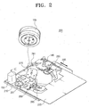
- Figure 4 is a perspective view illustrating the structure of a moving deck of a tape recorder according to the present invention;
- Figure 5 is a perspective view illustrating in detail the inner structure of the moving deck with a pole base assembly of Figure 5 in a loading position;
- Figure 6 is a sectional view taken on line VI-VI of Figure 5, illustrating the magnetic tape when loaded; and
- Figure 7 is a perspective view illustrating the structure of the stationary guide rail of the Figures 4 to 6 device.
- In the figures, elements having the same construction and function as those of the conventional tape recorders described with reference to Figures 1 to 3 are referred to by the same reference numerals, and further description thereof is omitted.
- Referring to Figures 4 to 7, a tape loading device of a moving
deck 300 of a tape recorder according to a preferred embodiment of the present invention includes amain chassis 310, asub chassis 320, apole base assembly 360, stationary andmovable guide rails movement prevention units movement prevention units pole base assembly 360 when the magnetic tape is loaded and unloaded and when the loading/unloading of the magnetic tape is completed. - The
main chassis 310 forms a bottom surface of themoving deck 300, and thehead drum 130 is mounted thereon. Thestationary guide rails 381 are integrally formed with a headdrum seating potion 215. The headdrum seating portion 215 seats thehead drum 130, and is formed by bending a part of themain chassis 310 to a predetermined angle. - The
sub chassis 320 is slidably mounted on themain chassis 310, and reciprocates with the loading/unloading of the magnetic tape (not shown) with respect to thehead drum 130 along themain chassis 310. - To provide compactness, the
main chassis 310 and thesub chassis 320 are formed to have different thicknesses. Themain chassis 310 has sufficient thickness to ensure sufficient strength to protect the internal parts of the movingdeck 300. Conversely, thesub chassis 320, which is moved along themain chassis 310, is formed to have a thickness as small as possible, so that the tape recorder can be light-weight. As can best be seen from Figure 6, themain chassis 310 has a thickness (a) of or about 1 mm, and thesub chassis 320 has a thickness (b) of or about 0.6 mm, to satisfy the conditions discussed above. Themain chassis 310 is formed of a metal plate, and thesub chassis 320 is preferably formed of an aluminium plate. - The
pole base assembly 360 is moved along themoving deck 300, taking a magnetic tape from a tape cassette (not shown) and winding the magnetic tape around as much as a half of the outer circumference of thehead drum 130. With loading completed, thepole base assembly 360 is secured at a loading position so that the magnetic tape can run in a close contact with thehead drum 130. There is a pair ofpole base assemblies 360 mounted on themoving deck 300, each facing one side of thehead drum 130. Eachpole base assembly 360 has abase member 361 moving on the movingdeck 300, and apole member 363 and aroller member 365 protruding from the upper surface of thebase member 361. Thepole base assembly 360 also includes a sub base 367 (see Figure 6) formed on the lower surface of thebase member 361. When the loading of the magnetic tape is completed, the leading end of thesub base 367 contacts afirst protrusion 393. Alink member 368 is moved by theloading motor 150 thereby to move thebase member 361. To ensure smooth movement of thepole base assembly 360, thelink member 368 is spaced from a lower surface of the stationary andmovable guide rails - The stationary and
movable guide rails pole base assembly 360 when it is moved with the loading/unloading of the magnetic tape. A pair of each of thestationary guide rails 381 and themovable guide rails 385, is formed on themain chassis 310 and thesub chassis 320 respectively. Thestationary guide rails 381 contact themovable guide rails 385 with movement of thesub chassis 320 along themain chassis 310 as the tape is loaded/unloaded. At approximately the centre of thestationary guide rail 381 and themovable guide rail 385 respectively, first andsecond guide grooves base member 361 therealong. - The
stationary guide rails 381 are formed by cutting a part of themain chassis 310 and bending the cut part upwardly at least once. Accordingly, thestationary guide rail 381 has the same thickness as themain chassis 310. A gap between the lower surface of thestationary guide rail 381 and the bottom surface of themain chassis 310 is such that the magnetic tape can be closely contacted with thehead drum 130 by movement of thepole member 363 of thepole base assembly 360 toward thehead drum 130 and/or theroller member 365. - The
movable guide rail 385 is integrally formed with and has the same thickness as thesub chassis 320. - Accordingly, the
stationary guide rail 381 is thicker than themovable guide rail 385. As such, when thestationary guide rails 381 and themovable guide rails 385 are connected to form a movement path for thepole base assembly 360 during the loading of the magnetic tape, a stepped portion (like t in Figure 3) as thick as the difference between the thicknesses of the stationary and themovable guide rails main chassis 310 has a thickness (a) of or about 1 mm, and thesub chassis 320 has a thickness (b) of or about 0.6 mm, the thickness of the stepped portion (t) at the connecting part between the stationary and themovable guide rails - In order to make up for the hindrance to the movement of the
pole base assembly 360 due to the presence of the stepped portion (t) at the connection part between the stationary and themovable guide rails stationary guide rail 381 or themovable guide rail 385, whichever is the thinnest. In the example shown, the thickness compensation means 391 protrudes from themovable guide rail 385. - Movement prevention unit constitutes an
extension portion 391 formed by bending and extending a side of themovable guide rail 385, i.e., bending and extending an inner rim of thesecond guide groove 385a downward at least once. Here, the distance (c) between the lower surface of theextended portion 391 and the lower surface of themovable guide rail 385 is the same as the thickness of the step (t, Figure 3) between the stationary and themovable guide rails extended portion 391 and the lower surface of themovable guide rail 385 is 0.4 mm. The distance between the opposite sides ofextended portion 391 of themovable guide rail 385 is substantially the same as the width (w, Figure 7) of thefirst guide groove 381a. Thesecond guide groove 385a is formed narrower than the width (w) of thefirst guide groove 381a, to provide room for theextended portion 391. - With the extended
portion 391 formed as described above, thepole base assembly 360 can be moved smoothly along the connecting part between the stationary and themovable guide rails - Although in the embodiment described above, the
extended portion 391 protrudes from the lower surface of themovable guide rail 385, this is not essential. Although not shown, if the distance from the bottom surface of themain chassis 310 to the lower surface of themovable guide rail 385 is identical to the distance from the bottom surface of themain chassis 310 to the lower surface of thestationary guide rail 381, theextended portion 391 instead protrudes upwardly of themovable guide rail 385. Furthermore, if themovable guide rail 385 is formed thicker than thestationary guide rail 381, theextended portion 391 instead is formed on thestationary guide rail 381. - Accordingly, the movement prevention unit for the tape loading device, referred to as levelling means 392 in Figure 4, prevents undesired movement by the
link member 368 and the magnetic tape when the magnetic tape is loaded. In this embodiment, the levelling means 392 also includes first andsecond protrusions - The
first protrusion 393 contacts thepole base assembly 360, instead of the support protrusion 175 of Figure 1, when the magnetic tape is loaded. Thefirst protrusion 393 protrudes downward from thestationary guide rail 381 to contact with the leading end of thesub base 367. It is preferable that thefirst protrusion 393 is integrally formed with thestationary guide rail 381. For example, thefirst protrusion 393 may be formed at the time of processing the pressing for themain chassis 310 so as to be formed together with thestationary guide rail 381 by the embossing. - The
second protrusion 395 restricts movement of thepole base assembly 360 in the 'B' direction of Figure 3 by maintaining a movement gap (G, Figure 6) between thelink member 368 and thestationary guide rail 381 during the loading/unloading of the magnetic tape, and when the loading/unloading of the magnetic tape is completed. More specifically, when the loading of the magnetic tape is completed, thesecond protrusion 395 prevents thepole base assembly 360 from moving upwardly when thepole base assembly 360 is at the loaded position. Thesecond protrusion 395 depends from the upper surface of thelink member 368, or alternatively from the lower surface of theguide rails stationary guide rail 381 and themovable guide rail 385 is opposed to the upper surface of thelink member 368 when the loading of the tape is completed. Preferably, the height of thesecond protrusion 395 is identical to that of the movement gap (G). In one embodiment, thesecond protrusion 395 is formed on the lower surface of thestationary guide rail 381 by embossing. Thesecond protrusion 395 can be formed together with thestationary guide rail 381 at the time of processing the pressing for themain chassis 310. Thesecond protrusion 395 may instead be formed in any suitable manner having any suitable shape. - For example, the
second protrusion 395 can be applied to a situation where a predetermined movement gap (G) has to be defined between thelink member 368 and theguide rails link member 368 contacting theguide rails pole base assembly 360. Accordingly, because the movement gap (G) between thelink member 368 and theguide rails pole base assembly 360, unwanted movement of thepole base assembly 360 is prevented. - The principles can also be applied to any other type of tape recorder, such as a video tape recorder (VTR) or a digital audio tape (DAT), both of which have a moving deck mechanism.
- According to the embodiments described above, formation of the stepped portion (t, Figure 3) on the connection part between the stationary and the
movable guide rails pole base assembly 360 after loading of the magnetic tape can also be restricted. As a result, thepole base assembly 360 moves in a stable manner during loading of the magnetic tape. Also, after the loading of the magnetic tape is complete, the magnetic tape can be run in a stable manner. - Also, in the case that the stationary and the
movable guide rails main chassis 310 and thesub chassis 320, respectively, the thickness of thesub chassis 320 can be thinner without suffering the disadvantages of the prior art, and, as a result, the tape recorder can be made more compact. Also, themain chassis 310 can be made to take any suitable thickness. - It will be understood by those skilled in the art that the present invention is not limited to the described preferred embodiments, but that various changes and modifications may be made within the scope of the invention as defined by the appended claims.
Claims (34)
the guide rail comprises a stationary guide rail and a movable guide rail mounted on the main chassis and the sub chassis, respectively, to be inter-docked with each other by the movement of the sub chassis.
the guide rail comprises a stationary guide rail and a movable guide rail mounted on the main chassis and the sub chassis, respectively, to be inter-locked with each other by the movement of the sub chassis.
Applications Claiming Priority (4)
| Application Number | Priority Date | Filing Date | Title |
|---|---|---|---|
| KR10-2002-0065236A KR100485784B1 (en) | 2002-10-24 | 2002-10-24 | A Magnetic Tape Extending Device of Tape Recorder |
| KR2002065236 | 2002-10-24 | ||
| KR10-2002-0088237A KR100513780B1 (en) | 2002-12-31 | 2002-12-31 | Tape loading device for tape recorder |
| KR2002088237 | 2002-12-31 |
Publications (2)
| Publication Number | Publication Date |
|---|---|
| EP1414032A2 true EP1414032A2 (en) | 2004-04-28 |
| EP1414032A3 EP1414032A3 (en) | 2006-12-13 |
Family
ID=32072573
Family Applications (1)
| Application Number | Title | Priority Date | Filing Date |
|---|---|---|---|
| EP03256727A Withdrawn EP1414032A3 (en) | 2002-10-24 | 2003-10-24 | Tape loading device |
Country Status (3)
| Country | Link |
|---|---|
| US (1) | US7032852B2 (en) |
| EP (1) | EP1414032A3 (en) |
| JP (1) | JP2004146044A (en) |
Families Citing this family (2)
| Publication number | Priority date | Publication date | Assignee | Title |
|---|---|---|---|---|
| JP2004310941A (en) * | 2003-04-09 | 2004-11-04 | Matsushita Electric Ind Co Ltd | Magnetic recording / reproducing device |
| KR20050120166A (en) * | 2004-06-18 | 2005-12-22 | 삼성전자주식회사 | Deck plate and magnetic recording and reproducing apparatus having the same |
Family Cites Families (15)
| Publication number | Priority date | Publication date | Assignee | Title |
|---|---|---|---|---|
| US4491885A (en) * | 1981-02-06 | 1985-01-01 | Matsushita Electric Industrial Co., Ltd. | Magnetic recording/playback device |
| US4476504A (en) * | 1981-05-04 | 1984-10-09 | Georges Michael P | Data cartridge tape drive assembly |
| US4556922A (en) * | 1981-09-08 | 1985-12-03 | U.S. Philips Corporation | VCR With improved tape threading and guiding |
| JPS59218661A (en) * | 1983-05-27 | 1984-12-08 | Canon Inc | Positioning device for tape draw-out means |
| JP2545358B2 (en) * | 1986-01-18 | 1996-10-16 | 株式会社日立製作所 | Rotating head type magnetic recording / reproducing device |
| US4985789A (en) * | 1987-10-02 | 1991-01-15 | Sanyo Electric Co., Ltd. | Signal recording-reproducing apparatus for use with cassette |
| JP2730237B2 (en) * | 1989-12-26 | 1998-03-25 | ソニー株式会社 | Tape loading device |
| JPH04313843A (en) * | 1991-04-12 | 1992-11-05 | Sony Corp | Tape guide device |
| JP3108704B2 (en) * | 1993-08-05 | 2000-11-13 | 三菱電機株式会社 | Tape loading mechanism |
| JP3148876B2 (en) * | 1993-09-17 | 2001-03-26 | 株式会社日立製作所 | Magnetic recording / reproducing device |
| JP3524215B2 (en) * | 1995-06-13 | 2004-05-10 | キヤノン株式会社 | Recording or playback device |
| KR0176580B1 (en) * | 1996-03-29 | 1999-04-15 | 김광호 | Pole base feeder for tape recorders |
| JPH09297950A (en) * | 1996-05-08 | 1997-11-18 | Toshiba Corp | Mover guidance device |
| JP3432779B2 (en) * | 1998-12-08 | 2003-08-04 | 三星電子株式会社 | Magnetic recording / reproducing device |
| JP2002100087A (en) * | 2000-09-25 | 2002-04-05 | Toshiba Video Products Japan Co Ltd | Tape loading device |
-
2003
- 2003-10-07 US US10/679,390 patent/US7032852B2/en not_active Expired - Fee Related
- 2003-10-15 JP JP2003355137A patent/JP2004146044A/en not_active Ceased
- 2003-10-24 EP EP03256727A patent/EP1414032A3/en not_active Withdrawn
Also Published As
| Publication number | Publication date |
|---|---|
| JP2004146044A (en) | 2004-05-20 |
| US7032852B2 (en) | 2006-04-25 |
| US20040079823A1 (en) | 2004-04-29 |
| EP1414032A3 (en) | 2006-12-13 |
Similar Documents
| Publication | Publication Date | Title |
|---|---|---|
| EP1414032A2 (en) | Tape loading device | |
| JPH0320918Y2 (en) | ||
| US5602695A (en) | Cassette loading mechanism for recording and playback apparatus | |
| KR100465166B1 (en) | Locking device of tape cassette housing for tape recorder | |
| KR100513780B1 (en) | Tape loading device for tape recorder | |
| US7239473B2 (en) | Tape guide mechanism of magnetic recording reproducing device | |
| US5497280A (en) | Cassette holder mechanism for magnetic recording/reproducing apparatus | |
| CN100373490C (en) | Tape loading device for tape recorders | |
| JPH06111437A (en) | Cassette detaching device | |
| US5579187A (en) | Tape loading mechanism with drum base | |
| JP3263792B2 (en) | Tape cassette | |
| KR100436370B1 (en) | Magnetic recording/reading apparatus | |
| JPS61187157A (en) | Tape loading device | |
| JP3037104B2 (en) | Leading guide block positioning mechanism | |
| JPH1186390A (en) | Tape pull-out mechanism for recording or playback device | |
| EP1626404A2 (en) | A tape deck | |
| US5196977A (en) | Tape guide mechanism for recording and reproducing device | |
| US20050180050A1 (en) | Tape guide device for magnetic recording and reproducing apparatus | |
| KR100422013B1 (en) | Supporting apparatus of Tape-end detecting sensor for magnetic recording/reading apparatus | |
| KR100512979B1 (en) | Cassette housing unit of the camcorder | |
| KR200218912Y1 (en) | Pin structure to position tape cassette in tape recorder | |
| EP1329891A2 (en) | Tape deck with integrally formed head drum mounting | |
| JPH07118174B2 (en) | Tape car ledge | |
| KR20030067980A (en) | guide rail alignment apparatus for Magnetic recording/reading apparatus | |
| JPS63266678A (en) | Floppy disk cassette |
Legal Events
| Date | Code | Title | Description |
|---|---|---|---|
| PUAI | Public reference made under article 153(3) epc to a published international application that has entered the european phase |
Free format text: ORIGINAL CODE: 0009012 |
|
| AK | Designated contracting states |
Kind code of ref document: A2 Designated state(s): AT BE BG CH CY CZ DE DK EE ES FI FR GB GR HU IE IT LI LU MC NL PT RO SE SI SK TR |
|
| AX | Request for extension of the european patent |
Extension state: AL LT LV MK |
|
| RAP1 | Party data changed (applicant data changed or rights of an application transferred) |
Owner name: SAMSUNG ELECTRONICS CO., LTD. |
|
| PUAL | Search report despatched |
Free format text: ORIGINAL CODE: 0009013 |
|
| AK | Designated contracting states |
Kind code of ref document: A3 Designated state(s): AT BE BG CH CY CZ DE DK EE ES FI FR GB GR HU IE IT LI LU MC NL PT RO SE SI SK TR |
|
| AX | Request for extension of the european patent |
Extension state: AL LT LV MK |
|
| 17P | Request for examination filed |
Effective date: 20070521 |
|
| 17Q | First examination report despatched |
Effective date: 20070710 |
|
| AKX | Designation fees paid |
Designated state(s): DE GB IT NL |
|
| GRAP | Despatch of communication of intention to grant a patent |
Free format text: ORIGINAL CODE: EPIDOSNIGR1 |
|
| STAA | Information on the status of an ep patent application or granted ep patent |
Free format text: STATUS: THE APPLICATION IS DEEMED TO BE WITHDRAWN |
|
| 18D | Application deemed to be withdrawn |
Effective date: 20090130 |