EP1414027A2 - Drive system for a scanning device of an information recording or reproduction device - Google Patents
Drive system for a scanning device of an information recording or reproduction device Download PDFInfo
- Publication number
- EP1414027A2 EP1414027A2 EP03292507A EP03292507A EP1414027A2 EP 1414027 A2 EP1414027 A2 EP 1414027A2 EP 03292507 A EP03292507 A EP 03292507A EP 03292507 A EP03292507 A EP 03292507A EP 1414027 A2 EP1414027 A2 EP 1414027A2
- Authority
- EP
- European Patent Office
- Prior art keywords
- gear
- drive system
- gear wheel
- toothed rack
- gear housing
- Prior art date
- Legal status (The legal status is an assumption and is not a legal conclusion. Google has not performed a legal analysis and makes no representation as to the accuracy of the status listed.)
- Granted
Links
Images

Classifications
-
- G—PHYSICS
- G11—INFORMATION STORAGE
- G11B—INFORMATION STORAGE BASED ON RELATIVE MOVEMENT BETWEEN RECORD CARRIER AND TRANSDUCER
- G11B7/00—Recording or reproducing by optical means, e.g. recording using a thermal beam of optical radiation by modifying optical properties or the physical structure, reproducing using an optical beam at lower power by sensing optical properties; Record carriers therefor
- G11B7/08—Disposition or mounting of heads or light sources relatively to record carriers
-
- G—PHYSICS
- G11—INFORMATION STORAGE
- G11B—INFORMATION STORAGE BASED ON RELATIVE MOVEMENT BETWEEN RECORD CARRIER AND TRANSDUCER
- G11B7/00—Recording or reproducing by optical means, e.g. recording using a thermal beam of optical radiation by modifying optical properties or the physical structure, reproducing using an optical beam at lower power by sensing optical properties; Record carriers therefor
- G11B7/08—Disposition or mounting of heads or light sources relatively to record carriers
- G11B7/085—Disposition or mounting of heads or light sources relatively to record carriers with provision for moving the light beam into, or out of, its operative position or across tracks, otherwise than during the transducing operation, e.g. for adjustment or preliminary positioning or track change or selection
- G11B7/0857—Arrangements for mechanically moving the whole head
- G11B7/08582—Sled-type positioners
-
- G—PHYSICS
- G11—INFORMATION STORAGE
- G11B—INFORMATION STORAGE BASED ON RELATIVE MOVEMENT BETWEEN RECORD CARRIER AND TRANSDUCER
- G11B21/00—Head arrangements not specific to the method of recording or reproducing
- G11B21/02—Driving or moving of heads
- G11B21/08—Track changing or selecting during transducing operation
- G11B21/081—Access to indexed tracks or parts of continuous track
- G11B21/083—Access to indexed tracks or parts of continuous track on discs
Definitions
- the invention relates to a drive system for a scanning device of an information recording or reproduction device, in which the scanning device reads or stores information or data in one or more tracks of a recording carrier.
- the recording carrier may in this case be a compact disc, known as a CD, a digital versatile disc, known as a DVD, a CD ROM or DVD ROM or a re-writable CD or DVD, or else a magnetooptical or other recording carrier.
- Devices for recording or reproducing information or data in one or more tracks of a recording carrier which are provided with a scanning device for reading or recording information, referred to as a "pickup", are generally known.
- the respective scanning device is usually arranged on a carriage which can move obliquely or perpendicularly with respect to the recording track.
- this carriage is coupled to a toothed rack, which is driven by an electric motor via a gear mechanism.
- the output shaft of the electric motor is provided for this purpose with a pinion or with a worm wheel, which is in engagement with the gear mechanism.
- the gear mechanism In order to prevent positional changes of the carriage, and consequently of the scanning device, when the drive is switched off or the electric motor is switched off, the gear mechanism is of a self-locking type of design. To meet the requirement for high positioning accuracy and short access time, a gear mechanism with a high transmission ratio is used.
- the toothed rack arrangement and the gear wheel driving the toothed rack are preferably formed with straight teeth, in order to avoid deflections of the scanning device in the direction of the recording carrier, such as the focusing direction in the case of an optical recording carrier, during tracking or track skipping and when reversing the driving direction.
- gear mechanisms are also greased, in order to avoid running noises.
- the use of lubricating grease for noise reduction entails the risk of the other components of the scanning device, especially the optical components, being soiled by the lubricating grease, whereby the functional capability of the scanning device is impaired. Therefore, the respective gear mechanism is usually accommodated in a housing, which may at the same time advantageously bring about a further reduction in noise.
- the invention consists in that the gear wheel mechanism of a drive system for a scanning device of an information recording or reproduction device which is in engagement with a toothed rack coupled to a carriage is secured on a supporting element and a dimensionally stable gear housing.
- the gear housing is pivotable to a predetermined degree together with the gear wheel mechanism about a spindle which is arranged perpendicular to the toothed rack and parallel to the gear spindles.
- the latter are likewise produced from a solid material and are not flexible.
- the arrangement and design of the gear housing, in particular of the pivoting spindle, make it possible for said housing to be pivoted together with the gear wheel mechanism as a whole against the toothed rack during the operation of the drive device and always kept in an exact and fixed engagement with the latter, in particular even when there is a reversal of the direction of movement of the drive system.
- the engagement optimized in this way has the effect of compensating for the play of the gear wheel or of the gear mechanism with respect to the toothed rack, which in turn increases the positioning accuracy of the carriage.
- the pressure which is thereby exerted on the gear wheel in engagement with the toothed rack, and its shaft or spindle, is also reduced.
- exact engagement, and the associated optimized running of the gear system reduces running noises.
- the gear housing is formed in such a way that it partly encloses and covers the gear wheel on the toothed rack side, so that undesired impairments of further components of the scanning device associated with lubrication of the gear mechanism are avoided.
- the drive system can be assembled in a reliable process. Production tolerances are also compensated, so that the risk of damage to the gear mechanism during normal operation is essentially ruled out.
- a guiding slot in which the end region of the gear wheel shaft on the supporting element side engages is formed in the supporting element.
- This guiding slot has a curvature with a radius which corresponds to the distance from the spindle of the gear wheel shaft to the pivoting spindle of the gear housing.
- the gear housing is connected to the supporting element via connecting means similar to bayonet fasteners. These are arranged and formed in such a way that their closing position, in which the gear housing is connected to the supporting element, is obtained when the arm is in its relaxed position - its position without any prestress.
- the connecting means are formed in such a way that they permit a pivoting movement of the gear housing within the predetermined limits without the gear housing being detached from the supporting element.
- the gear mechanism is self-locking and nevertheless the gear mechanism is protected from mechanical damage by the pivoting movement.
- the connecting means similar to bayonet fasteners permit considerably easier assembly.
- the gear mechanism is formed by a number of gear wheels, and the pivoting spindle is at the same time the spindle of an intermediate gear wheel included as part of the gear mechanism.
- the gear wheels may be produced from a flexible plastic and the spindles of the gear wheels are formed by webs of the gear housing.
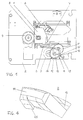
- the scanning device 1 represented in figure 1 is arranged on a supporting plate 2 and coupled to a drive system formed by an electric motor 3, a gear wheel mechanism 4 and a toothed rack 5 in engagement with the latter, the toothed rack 5 being integrally formed and securely connected to a carriage 7 guided on guiding rods 6.
- the carriage 7 bears the scanning device 1, which is intended for the scanning of optical recording carriers. It has an objective lens 8, which is used for focusing a light beam or laser beam for recording or playing back information or data on a recording carrier (not shown), which is detachably arranged on a turntable 9 by which the recording carrier is set in rotation.
- the gear wheel mechanism 4 is formed by two straight-toothed gear wheels 10 and 11, which are coupled to a gear housing 12 made of a dimensionally stable plastic, such as for example polypropylene.
- a gear housing 12 made of a dimensionally stable plastic, such as for example polypropylene.
- Integrally formed on the gear housing 12 are an arm 13, which is resilient due to the choice of the plastic, and also three bayonet hooks 14, which engage at clearances 15, 16 arranged in the supporting plate 2 and corresponding to them, the bayonet hooks 14 engaging behind the supporting plate 2 in the region of the clearances 15 in the connection position.
- the connection position is provided by the arm 13 engaging in the supporting plate 2 at a distance from the gear housing 12 and being relaxed.
- this arm 13 is easily pushed away to the side, in such a way that it is possible both for the latter to be pushed into the clearance 16 and for the bayonet hooks 14 to be pushed through the clearances 15.
- the latter relaxes as a result of its resilient property and turns the gear housing 12, and consequently also the bayonet hooks 14, so that the angled-away ends of the latter go under the supporting plate 2.
- the bayonet hooks 14 may be provided, according to figure 4, with a snap projection 26, which is directed radially with respect to the spindle 21 and brings about the assembly-facilitating effect that it engages with the supporting plate or snaps into it already after it has been pushed through the clearance 15, without turning into the connection position taking place.
- the snap projection represents an additional securement for the connection arrangement between the supporting plate 2, the gear wheel mechanism 4 and the gear housing 12.
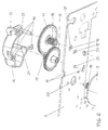
- Figure 2 shows the arrangement and formation of the gear wheel housing 4 and of the gear housing 12 coupled to the latter.
- the two straight-toothed gear wheels 10 and 11 are in engagement with each other via a pinion 17, arranged on the gear wheel 10 on the electric motor side
- the gear wheel 10 is in engagement with the electric motor 3 via a pinion 18 arranged on the output shaft of the latter
- the gear wheel 11 on the toothed rack side is in engagement with the toothed rack 5, not represented in this figure, via a pinion 19 arranged on it.
- the output shaft of the electric motor 3 protrudes with the pinion 18 through an opening 20 arranged in the supporting plate 2, from the underside to the upper side of the same, on which the gear wheels 10 and 11 and the gear housing 12 are secured.
- the gear housing 12 Arranged on the gear housing 12 are two spindles 21 and 22 for the gear wheels 10 and 11, which in the assembly position of the gear housing 12 are aligned perpendicularly with respect to the toothed rack 5.
- the spindle 21 thereby engages with its free end fixedly into a bore 23 formed in the supporting plate 2, and the spindle 22 receiving the gear wheel 11 on the toothed rack side engages in a curved long-hole guide 24, which has a radius of curvature which corresponds to the distance of the two spindles 21 and 22 from each other.
- the long-hole guide 24 permits a pivoting movement of the gear housing 12 and consequently of the spindle 22 and of the gear wheel 11 about the fixed spindle 21 and at the same time limits this movement by its length. In this case, the spindle 21 is at the same time the axis of rotation of the gear wheel 10.
- Figure 2 also clearly shows the bayonet hooks 14 formed on the gear housing 12 and the clearances 15 provided for them in the supporting plate 2. Also represented are the arm 13 and the clearance 16 provided for it. Formed in the latter is a detent 25, by which the arm 13 is fixed in a defined engagement position. This corresponds on the unactuated gear wheel mechanism 4 to the closed position of the bayonet hooks 14 and a relaxed arm 13.
- the gear housing 12 and the gear wheels 10 and 11 can only be disassembled by detaching the arm 13 from the clearance 16 while overcoming the detent 25.
- the gear wheel - and gear housing arrangement - are illustrated in an enlarged representation.
- the drive system is assembled by firstly screwing the electric motor 3 in its predetermined position onto the underside of the supporting plate 2, whereby it protrudes through the supporting plate 2 with the pinion 18 arranged on its output shaft. Subsequently, the two gear wheels 10 and 11 are pushed onto the spindles 21 and 22 in the gear housing 12 and preassembled in this way, the pinion 17 arranged on the gear wheel 10 coming into engagement with the gear wheel 11. After that, this preassembly unit is mounted in a simple way onto the supporting plate 2, by the bayonet hooks 14 and the free end of the arm 13 being inserted into the clearances 15 and 16 provided for them, the arm 13 or its free end having to be pressed to the side and stressed, in order to be able to snap into the clearance 16.
- the gear housing 12 is firmly pressed onto the supporting plate, whereby the angled portions of the bayonet hooks 14 go under the supporting plate 2 and, when the arm 13 is relaxed, are turned into their closed position, in which they can slide on the supporting plate 2 within the limits of the extent of the long-hole guide 24 for the spindle 22. Disassembly of the drive system takes place in a simple way, by the gear housing 12 being turned into the insertion position for the bayonet hooks 14 in the clearances 15 and pulled away from the supporting plate 2, so that the bayonet hooks 14 and the free end of the arm 13 disengage from the clearances 15 and 16.
- the gear wheel 11 on the toothed rack side is pressed against the toothed rack 5 independently of the direction of rotation of the electric motor 3, so that, by contrast with toothed racks complexly braced against one another, an integral toothed rack 5 is used and can be used.
- the gear mechanism is protected from mechanical damage by the resiliently supported pivotability of the gear housing 12.
- the gear housing 12, fastened onto the supporting plate 2 by bayonet hooks 14, has webs which advantageously form the spindles 21 and 22 of the gear wheels 10 and 11 and the gear housing 12 further serves both for noise reduction and for protection of the surroundings from influences of the gear mechanism, if for example it has lubricants.
Landscapes
- Moving Of Heads (AREA)
- Transmission Devices (AREA)
- Gear Transmission (AREA)
Abstract
Description
- The invention relates to a drive system for a scanning device of an information recording or reproduction device, in which the scanning device reads or stores information or data in one or more tracks of a recording carrier. The recording carrier may in this case be a compact disc, known as a CD, a digital versatile disc, known as a DVD, a CD ROM or DVD ROM or a re-writable CD or DVD, or else a magnetooptical or other recording carrier.
- Devices for recording or reproducing information or data in one or more tracks of a recording carrier which are provided with a scanning device for reading or recording information, referred to as a "pickup", are generally known. The respective scanning device is usually arranged on a carriage which can move obliquely or perpendicularly with respect to the recording track. To achieve a high speed and positioning accuracy, combined with a short access time to different locations of the recording carrier, this carriage is coupled to a toothed rack, which is driven by an electric motor via a gear mechanism. The output shaft of the electric motor is provided for this purpose with a pinion or with a worm wheel, which is in engagement with the gear mechanism. In order to prevent positional changes of the carriage, and consequently of the scanning device, when the drive is switched off or the electric motor is switched off, the gear mechanism is of a self-locking type of design. To meet the requirement for high positioning accuracy and short access time, a gear mechanism with a high transmission ratio is used. The toothed rack arrangement and the gear wheel driving the toothed rack are preferably formed with straight teeth, in order to avoid deflections of the scanning device in the direction of the recording carrier, such as the focusing direction in the case of an optical recording carrier, during tracking or track skipping and when reversing the driving direction.
- To reduce gear noises and to improve the tracking behavior of the gear mechanism, small gear modules are preferred, the gear elements of which must have high precision and the production of which requires great care. Generally, gear mechanisms are also greased, in order to avoid running noises. However, the use of lubricating grease for noise reduction entails the risk of the other components of the scanning device, especially the optical components, being soiled by the lubricating grease, whereby the functional capability of the scanning device is impaired. Therefore, the respective gear mechanism is usually accommodated in a housing, which may at the same time advantageously bring about a further reduction in noise.
- It is further known to use a flexible toothed rack or else an additional toothed rack on the scanning device side to minimize gear play. Similarly it is known to use coupling systems or flexible gear shafts or spindles or else flexible gear housings on the drive side, in order to protect the gear mechanism from mechanical damage. However, flexible gear shafts and/or flexible gear housings are problematical with regard to the accuracy of the system, because the gear wheel engagement is not optimal under normal circumstances and a flexible gear shaft or gear wheel shaft may bend under operational loading, to the detriment of accuracy. Additional elements in the drive system for the scanning device increase the diversity of the components, the care required and the effort involved in the assembly process, and consequently the production costs.
- It is therefore the object of the invention to design the drive system for a scanning device of an information recording or reproduction device according to the preamble of
claim 1 alternatively in such a way that it ensures a high speed and positioning accuracy of the carriage along with low noise development and simple assembly. - This object is achieved in the case of a drive system according to the preamble of
claim 1 by the defining features of the latter. Advantageous refinements are presented in the subclaims. - The invention consists in that the gear wheel mechanism of a drive system for a scanning device of an information recording or reproduction device which is in engagement with a toothed rack coupled to a carriage is secured on a supporting element and a dimensionally stable gear housing. In this case, the gear housing is pivotable to a predetermined degree together with the gear wheel mechanism about a spindle which is arranged perpendicular to the toothed rack and parallel to the gear spindles. The latter are likewise produced from a solid material and are not flexible. The arrangement and design of the gear housing, in particular of the pivoting spindle, make it possible for said housing to be pivoted together with the gear wheel mechanism as a whole against the toothed rack during the operation of the drive device and always kept in an exact and fixed engagement with the latter, in particular even when there is a reversal of the direction of movement of the drive system. The engagement optimized in this way has the effect of compensating for the play of the gear wheel or of the gear mechanism with respect to the toothed rack, which in turn increases the positioning accuracy of the carriage. The pressure which is thereby exerted on the gear wheel in engagement with the toothed rack, and its shaft or spindle, is also reduced. Furthermore, exact engagement, and the associated optimized running of the gear system, reduces running noises.
- The gear housing is formed in such a way that it partly encloses and covers the gear wheel on the toothed rack side, so that undesired impairments of further components of the scanning device associated with lubrication of the gear mechanism are avoided. The drive system can be assembled in a reliable process. Production tolerances are also compensated, so that the risk of damage to the gear mechanism during normal operation is essentially ruled out.
- In order that the shaft or spindle of the gear wheel on the toothed rack side can perform a movement corresponding to a pivoting movement of the gear housing, a guiding slot in which the end region of the gear wheel shaft on the supporting element side engages is formed in the supporting element. This guiding slot has a curvature with a radius which corresponds to the distance from the spindle of the gear wheel shaft to the pivoting spindle of the gear housing.
- Positioning of the gear housing, and consequently also of the gear mechanism, with respect to the toothed rack is made possible by means of a resilient arm which is formed on the gear housing and, at a distance from the latter, engages in a clearance which is formed in the supporting element and provided with a detent. The detent fixes the arm in a defined position. While the drive device is not in operation, the arm is relaxed. During operation, the gear mechanism is acted on by a drive torque. As a result, the gear mechanism and the gear housing coupled to it are pivoted about the pivoting spindle, so that the arm fixed by its free end in the supporting element is also pivoted along with it and prestressed as a result. This prestressing in turn causes a torque on the drive housing and the gear mechanism in such a way that the gear wheel on the toothed rack side is pressed against the toothed rack. As a result, an integral toothed rack can be used in an advantageous way.
- In a preferred embodiment, the gear housing is connected to the supporting element via connecting means similar to bayonet fasteners. These are arranged and formed in such a way that their closing position, in which the gear housing is connected to the supporting element, is obtained when the arm is in its relaxed position - its position without any prestress. In this case, the connecting means are formed in such a way that they permit a pivoting movement of the gear housing within the predetermined limits without the gear housing being detached from the supporting element. The gear mechanism is self-locking and nevertheless the gear mechanism is protected from mechanical damage by the pivoting movement. The connecting means similar to bayonet fasteners permit considerably easier assembly.
- In a preferred embodiment, the gear mechanism is formed by a number of gear wheels, and the pivoting spindle is at the same time the spindle of an intermediate gear wheel included as part of the gear mechanism. The gear wheels may be produced from a flexible plastic and the spindles of the gear wheels are formed by webs of the gear housing.
- The invention is explained below in drawings on the basis of an exemplary embodiment. In the associated drawings:
- figure 1
- shows a plan view of a scanning device,
- figure 2
- shows an exploded representation of the gear wheel mechanism coupled to a gear housing,
- figure 3
- shows a plan view of this, enlarged, and
- figure 4
- shows a bayonet hook in engagement with a supporting plate, greatly enlarged.
- The
scanning device 1 represented in figure 1 is arranged on a supportingplate 2 and coupled to a drive system formed by anelectric motor 3, agear wheel mechanism 4 and atoothed rack 5 in engagement with the latter, thetoothed rack 5 being integrally formed and securely connected to acarriage 7 guided on guiding rods 6. Thecarriage 7 bears thescanning device 1, which is intended for the scanning of optical recording carriers. It has anobjective lens 8, which is used for focusing a light beam or laser beam for recording or playing back information or data on a recording carrier (not shown), which is detachably arranged on a turntable 9 by which the recording carrier is set in rotation. Thegear wheel mechanism 4 is formed by two straight-toothed gear wheels gear housing 12 made of a dimensionally stable plastic, such as for example polypropylene. Integrally formed on thegear housing 12 are anarm 13, which is resilient due to the choice of the plastic, and also threebayonet hooks 14, which engage atclearances 15, 16 arranged in the supportingplate 2 and corresponding to them, thebayonet hooks 14 engaging behind the supportingplate 2 in the region of theclearances 15 in the connection position. The connection position is provided by thearm 13 engaging in the supportingplate 2 at a distance from thegear housing 12 and being relaxed. For the assembly of thegear housing 12, thisarm 13 is easily pushed away to the side, in such a way that it is possible both for the latter to be pushed into the clearance 16 and for thebayonet hooks 14 to be pushed through theclearances 15. By removing the pressure from thearm 13, the latter relaxes as a result of its resilient property and turns thegear housing 12, and consequently also thebayonet hooks 14, so that the angled-away ends of the latter go under the supportingplate 2. - As an alternative to the embodiment described above, the
bayonet hooks 14 may be provided, according to figure 4, with asnap projection 26, which is directed radially with respect to thespindle 21 and brings about the assembly-facilitating effect that it engages with the supporting plate or snaps into it already after it has been pushed through theclearance 15, without turning into the connection position taking place. The snap projection represents an additional securement for the connection arrangement between the supportingplate 2, thegear wheel mechanism 4 and thegear housing 12. - Figure 2 shows the arrangement and formation of the
gear wheel housing 4 and of thegear housing 12 coupled to the latter. The two straight-toothed gear wheels pinion 17, arranged on thegear wheel 10 on the electric motor side, thegear wheel 10 is in engagement with theelectric motor 3 via apinion 18 arranged on the output shaft of the latter and thegear wheel 11 on the toothed rack side is in engagement with thetoothed rack 5, not represented in this figure, via apinion 19 arranged on it. In this case, the output shaft of theelectric motor 3 protrudes with thepinion 18 through anopening 20 arranged in the supportingplate 2, from the underside to the upper side of the same, on which thegear wheels gear housing 12 are secured. - Arranged on the
gear housing 12 are twospindles gear wheels gear housing 12 are aligned perpendicularly with respect to thetoothed rack 5. Thespindle 21 thereby engages with its free end fixedly into abore 23 formed in the supportingplate 2, and thespindle 22 receiving thegear wheel 11 on the toothed rack side engages in a curved long-hole guide 24, which has a radius of curvature which corresponds to the distance of the twospindles gear housing 12 and consequently of thespindle 22 and of thegear wheel 11 about the fixedspindle 21 and at the same time limits this movement by its length. In this case, thespindle 21 is at the same time the axis of rotation of thegear wheel 10. - Figure 2 also clearly shows the bayonet hooks 14 formed on the
gear housing 12 and theclearances 15 provided for them in the supportingplate 2. Also represented are thearm 13 and the clearance 16 provided for it. Formed in the latter is adetent 25, by which thearm 13 is fixed in a defined engagement position. This corresponds on the unactuatedgear wheel mechanism 4 to the closed position of the bayonet hooks 14 and arelaxed arm 13. Thegear housing 12 and thegear wheels arm 13 from the clearance 16 while overcoming thedetent 25. In figure 3, the gear wheel - and gear housing arrangement - are illustrated in an enlarged representation. - The drive system is assembled by firstly screwing the
electric motor 3 in its predetermined position onto the underside of the supportingplate 2, whereby it protrudes through the supportingplate 2 with thepinion 18 arranged on its output shaft. Subsequently, the twogear wheels spindles gear housing 12 and preassembled in this way, thepinion 17 arranged on thegear wheel 10 coming into engagement with thegear wheel 11. After that, this preassembly unit is mounted in a simple way onto the supportingplate 2, by the bayonet hooks 14 and the free end of thearm 13 being inserted into theclearances 15 and 16 provided for them, thearm 13 or its free end having to be pressed to the side and stressed, in order to be able to snap into the clearance 16. As this happens, thepinion 18 comes into engagement with thegear wheel 10 and thepinion 19 comes into engagement with thetoothed rack 5. Thegear housing 12 is firmly pressed onto the supporting plate, whereby the angled portions of the bayonet hooks 14 go under the supportingplate 2 and, when thearm 13 is relaxed, are turned into their closed position, in which they can slide on the supportingplate 2 within the limits of the extent of the long-hole guide 24 for thespindle 22. Disassembly of the drive system takes place in a simple way, by thegear housing 12 being turned into the insertion position for the bayonet hooks 14 in theclearances 15 and pulled away from the supportingplate 2, so that the bayonet hooks 14 and the free end of thearm 13 disengage from theclearances 15 and 16. - The
gear wheel 11, which is pivotable about thespindle 21 within the limits of the extent of the long-hole guide 24 , is in an exact and fixed engagement with thetoothed rack 5, thegear housing 12 with thespindle 21 being prepositioned by thearm 13. A change in the direction of rotation of the gear wheel mechanism caused by a controlled reversal of the drive direction of theelectric motor 3, associated with a reversal of the torque, is taken up by thegear housing 12, which is pivotable about thespindle 21, and theprestressable arm 13, and play occurring between thegear wheel 11 and thetoothed rack 5 is compensated. Thegear wheel 11 on the toothed rack side is pressed against thetoothed rack 5 independently of the direction of rotation of theelectric motor 3, so that, by contrast with toothed racks complexly braced against one another, an integraltoothed rack 5 is used and can be used. On the other hand, the gear mechanism is protected from mechanical damage by the resiliently supported pivotability of thegear housing 12. Thegear housing 12, fastened onto the supportingplate 2 by bayonet hooks 14, has webs which advantageously form thespindles gear wheels gear housing 12 further serves both for noise reduction and for protection of the surroundings from influences of the gear mechanism, if for example it has lubricants. -
- 1
- scanning device
- 2
- supporting plate
- 3
- electric motor
- 4
- gear wheel mechanism
- 5
- toothed rack
- 6
- guiding rod
- 7
- carriage
- 8
- objective lens
- 9
- turntable
- 10
- gear wheel
- 11
- gear wheel
- 12
- gear housing
- 13
- arm
- 14
- bayonet hook
- 15
- clearance
- 16
- clearance
- 17
- pinion
- 18
- pinion
- 19
- pinion
- 20
- opening
- 21
- spindle
- 22
- spindle
- 23
- bore
- 24
- long-hole guide
- 25
- detent
- 26
- snap projection
Claims (10)
- A drive system for a scanning device of an information recording or reproduction device, with a carriage coupled to a toothed rack, a gear mechanism driving the toothed rack and a gear housing, wherein the gear wheel mechanism (4) is secured on a supporting element (2) and the gear housing (12), the gear housing (12) consisting of a dimensionally stable material and being pivotable with the gear wheel mechanism (4) about a spindle (21) which is arranged perpendicularly with respect to the toothed rack (5).
- A drive system according to claim 1, wherein the spindle (22) of the gear wheel (11) on the toothed rack side of the gear wheel mechanism (4) engages in a guiding slot (24) which is formed in the supporting element (2) and permits a movement of the spindle (22) and of the gear wheel (11) corresponding to the pivoting movement of the gear housing (12).
- A drive system according to claim 1, wherein the gear housing (12) has a resilient arm (13), which at a distance from the gear housing (12) engages in an opening (16) formed in the supporting element (2) and is prestressed when there is a pivoting movement, and wherein a detent (25), by which the arm (13) is fixed in a defined engagement position, is formed in the opening (16).
- A drive system according to claim 1, wherein the gear housing (12) is connected to the supporting element (2) via a connection similar to bayonet fasteners, the engaging connecting elements (14) being arranged in such a way that their closing position is obtained in the position of the arm (13) without any prestress.
- A drive system according to claim 4, wherein the connecting elements (14) are provided with a snap projection (26), formed transversely with respect to the pivoting direction of the gear housing (12), for the engagement with the supporting element (2).
- A drive system according to claim 1, wherein the pivoting spindle (21) of the gear housing (12) is at the same time the spindle (22) of an intermediate gear wheel (10) included as part of the gear wheel mechanism (4).
- A drive system according to one of the preceding claims, wherein the gear wheels (10, 11) consist of a flexible plastic.
- A drive system according to claim 1, wherein the spindles (21, 22) of the gear wheel mechanism (4) are formed by webs of the gear housing (12).
- A drive system according to claim 1, wherein the gear wheel mechanism (4) is provided such that the gear wheel (11) on the toothed rack side is pressing against the toothed rack (5) independently of its direction of rotation.
- A drive system according to claim 9, wherein the toothed rack (5) is integrally formed.
Applications Claiming Priority (2)
| Application Number | Priority Date | Filing Date | Title |
|---|---|---|---|
| DE10249322A DE10249322A1 (en) | 2002-10-22 | 2002-10-22 | Drive system for a scanner of an information recording or reproducing device |
| DE10249322 | 2002-10-22 |
Publications (3)
| Publication Number | Publication Date |
|---|---|
| EP1414027A2 true EP1414027A2 (en) | 2004-04-28 |
| EP1414027A3 EP1414027A3 (en) | 2006-08-30 |
| EP1414027B1 EP1414027B1 (en) | 2008-05-14 |
Family
ID=32049554
Family Applications (1)
| Application Number | Title | Priority Date | Filing Date |
|---|---|---|---|
| EP03292507A Expired - Lifetime EP1414027B1 (en) | 2002-10-22 | 2003-10-10 | Drive system for a scanning device of an information recording or reproduction device |
Country Status (6)
| Country | Link |
|---|---|
| US (1) | US7024673B2 (en) |
| EP (1) | EP1414027B1 (en) |
| JP (1) | JP2004146047A (en) |
| KR (1) | KR20040035554A (en) |
| CN (1) | CN100511461C (en) |
| DE (2) | DE10249322A1 (en) |
Families Citing this family (3)
| Publication number | Priority date | Publication date | Assignee | Title |
|---|---|---|---|---|
| JP2004355735A (en) * | 2003-05-29 | 2004-12-16 | Toshiba Corp | Optical head device, optical head transfer method, optical disk device |
| CN1897148A (en) * | 2005-07-15 | 2007-01-17 | 鸿富锦精密工业(深圳)有限公司 | Information recording/reproducer |
| CN111855570B (en) * | 2020-06-09 | 2024-06-14 | 北京旷视科技有限公司 | Wheel hub detection device and wheel hub detection method |
Family Cites Families (6)
| Publication number | Priority date | Publication date | Assignee | Title |
|---|---|---|---|---|
| JPS6121418A (en) * | 1984-07-05 | 1986-01-30 | Matsushita Electric Ind Co Ltd | Support device for mover |
| JPH039186Y2 (en) * | 1985-06-26 | 1991-03-07 | ||
| JPS6231072A (en) * | 1985-08-02 | 1987-02-10 | Olympus Optical Co Ltd | Sliding feeder for optical pickup |
| JPS6318525A (en) * | 1986-07-10 | 1988-01-26 | Brother Ind Ltd | Input and output device for optical disk |
| WO1995008172A1 (en) * | 1993-09-13 | 1995-03-23 | Sony Corporation | Method of assembling disk unit and head carriage driving transmission gear |
| JP4041569B2 (en) * | 1997-12-26 | 2008-01-30 | クラリオン株式会社 | Disc player |
-
2002
- 2002-10-22 DE DE10249322A patent/DE10249322A1/en not_active Withdrawn
-
2003
- 2003-09-30 KR KR1020030067739A patent/KR20040035554A/en not_active Withdrawn
- 2003-10-10 DE DE60320917T patent/DE60320917D1/en not_active Expired - Lifetime
- 2003-10-10 EP EP03292507A patent/EP1414027B1/en not_active Expired - Lifetime
- 2003-10-16 US US10/685,087 patent/US7024673B2/en not_active Expired - Fee Related
- 2003-10-21 JP JP2003360424A patent/JP2004146047A/en active Pending
- 2003-10-22 CN CNB2003101027408A patent/CN100511461C/en not_active Expired - Fee Related
Also Published As
| Publication number | Publication date |
|---|---|
| EP1414027B1 (en) | 2008-05-14 |
| EP1414027A3 (en) | 2006-08-30 |
| CN100511461C (en) | 2009-07-08 |
| US20040170111A1 (en) | 2004-09-02 |
| CN1497594A (en) | 2004-05-19 |
| KR20040035554A (en) | 2004-04-29 |
| DE60320917D1 (en) | 2008-06-26 |
| JP2004146047A (en) | 2004-05-20 |
| US7024673B2 (en) | 2006-04-04 |
| DE10249322A1 (en) | 2004-05-06 |
Similar Documents
| Publication | Publication Date | Title |
|---|---|---|
| US20010008510A1 (en) | Disk drive | |
| EP1414027B1 (en) | Drive system for a scanning device of an information recording or reproduction device | |
| EP1070317B1 (en) | Apparatus for the recording or for the reproduction of information with a drive system for a scanning device | |
| US5727422A (en) | Rack drive | |
| JPH0963213A (en) | Optical disk drive | |
| JPH05325202A (en) | Optical pickup driving device | |
| JP3158375B2 (en) | Optical pickup feeder | |
| JP3725334B2 (en) | Optical head feeder | |
| JPS63304476A (en) | Optical pickup drive device | |
| JP3504694B2 (en) | Pickup feed mechanism | |
| MXPA00009874A (en) | Apparatus for the recording or for the reproduction of information with a drive system for a scanning device | |
| KR100252123B1 (en) | Double Gear for Optical Pickup Conveyor | |
| JP2004316661A (en) | Rack and pinion equipment | |
| KR100242013B1 (en) | Backlash eliminator for optical disc player | |
| JPH0855452A (en) | Feeding mechanism | |
| KR980011240A (en) | The optical disk rotating device of the disk player | |
| CN101266806A (en) | CD read/write device | |
| JP2005302285A (en) | Recording or reproducing apparatus for optical recording medium | |
| KR19980063270U (en) | Optical Pickup Transfer Device | |
| JP2002304860A (en) | Transmission mechanism | |
| KR19980013981U (en) | Optical pickup backlash prevention device in compact disc player | |
| JP2004022054A (en) | Optical disk drive | |
| JP2008210459A (en) | Disk drive device | |
| JPH0611114U (en) | Optical pickup device | |
| JPH11154382A (en) | Mechanism for feeding optical pickup in disk drive device |
Legal Events
| Date | Code | Title | Description |
|---|---|---|---|
| PUAI | Public reference made under article 153(3) epc to a published international application that has entered the european phase |
Free format text: ORIGINAL CODE: 0009012 |
|
| AK | Designated contracting states |
Kind code of ref document: A2 Designated state(s): AT BE BG CH CY CZ DE DK EE ES FI FR GB GR HU IE IT LI LU MC NL PT RO SE SI SK TR |
|
| AX | Request for extension of the european patent |
Extension state: AL LT LV MK |
|
| RAP1 | Party data changed (applicant data changed or rights of an application transferred) |
Owner name: THOMSON LICENSING |
|
| PUAL | Search report despatched |
Free format text: ORIGINAL CODE: 0009013 |
|
| AK | Designated contracting states |
Kind code of ref document: A3 Designated state(s): AT BE BG CH CY CZ DE DK EE ES FI FR GB GR HU IE IT LI LU MC NL PT RO SE SI SK TR |
|
| AX | Request for extension of the european patent |
Extension state: AL LT LV MK |
|
| 17P | Request for examination filed |
Effective date: 20070226 |
|
| AKX | Designation fees paid |
Designated state(s): DE FR GB |
|
| GRAP | Despatch of communication of intention to grant a patent |
Free format text: ORIGINAL CODE: EPIDOSNIGR1 |
|
| GRAS | Grant fee paid |
Free format text: ORIGINAL CODE: EPIDOSNIGR3 |
|
| GRAA | (expected) grant |
Free format text: ORIGINAL CODE: 0009210 |
|
| AK | Designated contracting states |
Kind code of ref document: B1 Designated state(s): DE FR GB |
|
| REG | Reference to a national code |
Ref country code: GB Ref legal event code: FG4D |
|
| REF | Corresponds to: |
Ref document number: 60320917 Country of ref document: DE Date of ref document: 20080626 Kind code of ref document: P |
|
| REG | Reference to a national code |
Ref country code: GB Ref legal event code: 746 Effective date: 20080616 |
|
| PLBE | No opposition filed within time limit |
Free format text: ORIGINAL CODE: 0009261 |
|
| STAA | Information on the status of an ep patent application or granted ep patent |
Free format text: STATUS: NO OPPOSITION FILED WITHIN TIME LIMIT |
|
| 26N | No opposition filed |
Effective date: 20090217 |
|
| PGFP | Annual fee paid to national office [announced via postgrant information from national office to epo] |
Ref country code: GB Payment date: 20090930 Year of fee payment: 7 |
|
| PGFP | Annual fee paid to national office [announced via postgrant information from national office to epo] |
Ref country code: DE Payment date: 20091026 Year of fee payment: 7 |
|
| PGFP | Annual fee paid to national office [announced via postgrant information from national office to epo] |
Ref country code: FR Payment date: 20091117 Year of fee payment: 7 |
|
| GBPC | Gb: european patent ceased through non-payment of renewal fee |
Effective date: 20101010 |
|
| PG25 | Lapsed in a contracting state [announced via postgrant information from national office to epo] |
Ref country code: FR Free format text: LAPSE BECAUSE OF NON-PAYMENT OF DUE FEES Effective date: 20101102 |
|
| REG | Reference to a national code |
Ref country code: FR Ref legal event code: ST Effective date: 20110630 |
|
| PG25 | Lapsed in a contracting state [announced via postgrant information from national office to epo] |
Ref country code: GB Free format text: LAPSE BECAUSE OF NON-PAYMENT OF DUE FEES Effective date: 20101010 |
|
| REG | Reference to a national code |
Ref country code: DE Ref legal event code: R119 Ref document number: 60320917 Country of ref document: DE Effective date: 20110502 |
|
| PG25 | Lapsed in a contracting state [announced via postgrant information from national office to epo] |
Ref country code: DE Free format text: LAPSE BECAUSE OF NON-PAYMENT OF DUE FEES Effective date: 20110502 |