EP1413513B1 - Aircraft with multipurpose lower decks and associated methods of manufacture - Google Patents
Aircraft with multipurpose lower decks and associated methods of manufacture Download PDFInfo
- Publication number
- EP1413513B1 EP1413513B1 EP03078139A EP03078139A EP1413513B1 EP 1413513 B1 EP1413513 B1 EP 1413513B1 EP 03078139 A EP03078139 A EP 03078139A EP 03078139 A EP03078139 A EP 03078139A EP 1413513 B1 EP1413513 B1 EP 1413513B1
- Authority
- EP
- European Patent Office
- Prior art keywords
- aircraft
- passenger
- fuselage
- cargo
- deck
- Prior art date
- Legal status (The legal status is an assumption and is not a legal conclusion. Google has not performed a legal analysis and makes no representation as to the accuracy of the status listed.)
- Expired - Lifetime
Links
- 238000000034 method Methods 0.000 title claims description 6
- 238000004519 manufacturing process Methods 0.000 title claims description 3
- 230000004888 barrier function Effects 0.000 claims description 2
- 239000003381 stabilizer Substances 0.000 claims description 2
- 208000033255 Progressive myoclonic epilepsy type 1 Diseases 0.000 description 2
- 230000003068 static effect Effects 0.000 description 2
- 241000272517 Anseriformes Species 0.000 description 1
- XAGFODPZIPBFFR-UHFFFAOYSA-N aluminium Chemical compound [Al] XAGFODPZIPBFFR-UHFFFAOYSA-N 0.000 description 1
- 229910052782 aluminium Inorganic materials 0.000 description 1
- 150000001875 compounds Chemical class 0.000 description 1
- 239000000463 material Substances 0.000 description 1
- 238000012986 modification Methods 0.000 description 1
- 230000004048 modification Effects 0.000 description 1
Images

Classifications
-
- B—PERFORMING OPERATIONS; TRANSPORTING
- B64—AIRCRAFT; AVIATION; COSMONAUTICS
- B64C—AEROPLANES; HELICOPTERS
- B64C1/00—Fuselages; Constructional features common to fuselages, wings, stabilising surfaces or the like
- B64C1/0009—Aerodynamic aspects
-
- B—PERFORMING OPERATIONS; TRANSPORTING
- B64—AIRCRAFT; AVIATION; COSMONAUTICS
- B64C—AEROPLANES; HELICOPTERS
- B64C1/00—Fuselages; Constructional features common to fuselages, wings, stabilising surfaces or the like
- B64C1/26—Attaching the wing or tail units or stabilising surfaces
-
- B—PERFORMING OPERATIONS; TRANSPORTING
- B64—AIRCRAFT; AVIATION; COSMONAUTICS
- B64C—AEROPLANES; HELICOPTERS
- B64C25/00—Alighting gear
- B64C25/02—Undercarriages
- B64C25/04—Arrangement or disposition on aircraft
-
- B—PERFORMING OPERATIONS; TRANSPORTING
- B64—AIRCRAFT; AVIATION; COSMONAUTICS
- B64C—AEROPLANES; HELICOPTERS
- B64C25/00—Alighting gear
- B64C25/02—Undercarriages
- B64C25/08—Undercarriages non-fixed, e.g. jettisonable
- B64C25/10—Undercarriages non-fixed, e.g. jettisonable retractable, foldable, or the like
-
- B—PERFORMING OPERATIONS; TRANSPORTING
- B64—AIRCRAFT; AVIATION; COSMONAUTICS
- B64D—EQUIPMENT FOR FITTING IN OR TO AIRCRAFT; FLIGHT SUITS; PARACHUTES; ARRANGEMENT OR MOUNTING OF POWER PLANTS OR PROPULSION TRANSMISSIONS IN AIRCRAFT
- B64D11/00—Passenger or crew accommodation; Flight-deck installations not otherwise provided for
-
- B—PERFORMING OPERATIONS; TRANSPORTING
- B64—AIRCRAFT; AVIATION; COSMONAUTICS
- B64D—EQUIPMENT FOR FITTING IN OR TO AIRCRAFT; FLIGHT SUITS; PARACHUTES; ARRANGEMENT OR MOUNTING OF POWER PLANTS OR PROPULSION TRANSMISSIONS IN AIRCRAFT
- B64D27/00—Arrangement or mounting of power plants in aircraft; Aircraft characterised by the type or position of power plants
- B64D27/02—Aircraft characterised by the type or position of power plants
- B64D27/16—Aircraft characterised by the type or position of power plants of jet type
- B64D27/18—Aircraft characterised by the type or position of power plants of jet type within, or attached to, wings
-
- B—PERFORMING OPERATIONS; TRANSPORTING
- B64—AIRCRAFT; AVIATION; COSMONAUTICS
- B64D—EQUIPMENT FOR FITTING IN OR TO AIRCRAFT; FLIGHT SUITS; PARACHUTES; ARRANGEMENT OR MOUNTING OF POWER PLANTS OR PROPULSION TRANSMISSIONS IN AIRCRAFT
- B64D37/00—Arrangements in connection with fuel supply for power plant
- B64D37/02—Tanks
- B64D37/04—Arrangement thereof in or on aircraft
-
- B—PERFORMING OPERATIONS; TRANSPORTING
- B64—AIRCRAFT; AVIATION; COSMONAUTICS
- B64D—EQUIPMENT FOR FITTING IN OR TO AIRCRAFT; FLIGHT SUITS; PARACHUTES; ARRANGEMENT OR MOUNTING OF POWER PLANTS OR PROPULSION TRANSMISSIONS IN AIRCRAFT
- B64D9/00—Equipment for handling freight; Equipment for facilitating passenger embarkation or the like
- B64D9/003—Devices for retaining pallets or freight containers
-
- B—PERFORMING OPERATIONS; TRANSPORTING
- B64—AIRCRAFT; AVIATION; COSMONAUTICS
- B64C—AEROPLANES; HELICOPTERS
- B64C1/00—Fuselages; Constructional features common to fuselages, wings, stabilising surfaces or the like
- B64C2001/0018—Fuselages; Constructional features common to fuselages, wings, stabilising surfaces or the like comprising two decks adapted for carrying passengers only
- B64C2001/0027—Fuselages; Constructional features common to fuselages, wings, stabilising surfaces or the like comprising two decks adapted for carrying passengers only arranged one above the other
-
- B—PERFORMING OPERATIONS; TRANSPORTING
- B64—AIRCRAFT; AVIATION; COSMONAUTICS
- B64C—AEROPLANES; HELICOPTERS
- B64C1/00—Fuselages; Constructional features common to fuselages, wings, stabilising surfaces or the like
- B64C2001/0045—Fuselages characterised by special shapes
-
- Y—GENERAL TAGGING OF NEW TECHNOLOGICAL DEVELOPMENTS; GENERAL TAGGING OF CROSS-SECTIONAL TECHNOLOGIES SPANNING OVER SEVERAL SECTIONS OF THE IPC; TECHNICAL SUBJECTS COVERED BY FORMER USPC CROSS-REFERENCE ART COLLECTIONS [XRACs] AND DIGESTS
- Y02—TECHNOLOGIES OR APPLICATIONS FOR MITIGATION OR ADAPTATION AGAINST CLIMATE CHANGE
- Y02T—CLIMATE CHANGE MITIGATION TECHNOLOGIES RELATED TO TRANSPORTATION
- Y02T50/00—Aeronautics or air transport
- Y02T50/10—Drag reduction
Definitions
- the following disclosure relates generally to multideck aircraft and, more particularly, to transonic aircraft having multipurpose lower decks for carrying passengers or passengers and cargo.
- Conventional transport aircraft typically include a passenger cabin on an upper deck and a cargo hold on a lower deck. This configuration allows airlines to generate revenue by transporting both passengers and cargo over selected routes. On some routes, however, there is a greater demand for transporting passengers than cargo. On these routes, the airlines may accordingly prefer to use some of the space on the lower cargo deck for additional passenger seating.
- Beuck discloses an energy absorbing structural unit that is attached to the underside of an aircraft fuselage.
- the structural unit proposed by Beuck is an add-on feature of considerate size that extends downwardly and outwardly around the lower half of the fuselage cross-section to protect a lower passenger deck in the event of an impact. Because of its size and complexity, implementing the Beuck approach may add considerable cost, weight and aerodynamic drag to an aircraft.
- US-A-5992797 which is regarded as the closest prior art, discloses a subsonic aircraft having the main and upper passenger seating decks both above the wing
- an aircraft according to claim 1 includes a first fuselage portion and a second fuselage portion positioned aft of the first fuselage portion.
- the first fuselage portion can have a first dimension at least approximately parallel to a yaw axis
- the second fuselage portion can have a second dimension at least approximately parallel to the yaw axis that is less than the first dimension.
- the aircraft fuselage can further include a first deck and a second deck.
- the first deck can extend at least within the first and second fuselage portions, and can have a first passenger portion configured to accommodate passengers.
- the second deck can extend at least within the first fuselage portion, and can have a second passenger portion configured to accommodate passengers.
- the second deck can further include a cargo portion configured to carry cargo containers.
- the aircraft fuselage can also include a third fuselage portion positioned aft of the second fuselage portion.
- the third fuselage portion can have a third dimension at least approximately parallel to the yaw axis that is greater than the second dimension.
- the first deck can extend within the third fuselage portion.
- a method for manufacturing an aircraft includes providing a first fuselage portion and attaching a second fuselage portion to the first fuselage portion aft of the first fuselage portion.
- the first fuselage portion can have a first dimension at least approximately parallel to a yaw axis
- the second fuselage portion can have a second dimension at least approximately parallel to the yaw axis that is less than the first dimension.
- the method can further include positioning a wing at least proximate to the second fuselage portion, extending at least generally outboard relative to the second fuselage portion.
- the method can additionally include positioning a first deck at least within the first and second fuselage portions, and positioning a second deck at least within the first fuselage portion.
- the first deck can include a first passenger portion configured to accommodate passengers
- the second deck can include a second passenger portion configured to accommodate passengers.
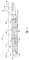
- Figure 1 is a partially hidden side elevation view of an aircraft 100 having a fuselage 102 with a multipurpose lower deck 108 configured in accordance with an embodiment of the invention.
- the fuselage 102 includes a first fuselage portion 110 and a second fuselage portion 120 positioned aft of the first fuselage portion 110.
- the second fuselage portion 120 can be positioned at least proximate to a wing 150.
- the fuselage 102 can further include a third fuselage portion 130 positioned aft of the second fuselage portion 120, and an empennage portion 140 positioned aft of the third fuselage portion 130.
- the empennage portion 140 can include a vertical stabilizer 142 for controlling motion of the aircraft 100 about a yaw axis 104 in flight.
- the fuselage 102 is an "area-ruled" fuselage configured to reduce transonic wave drag.
- the first fuselage portion 110 can have a first dimension 111 at least approximately parallel to the yaw axis 104
- the second fuselage portion 120 can have a second dimension 112 at least approximately parallel to the yaw axis 104 and less than the first dimension 111
- the third fuselage portion 130 can have a third dimension 113 at least approximately parallel to the yaw axis 104 and greater than the second dimension 112.
- the illustrated fuselage vertical area-ruling contributes to the overall cross-sectional area-ruling of the fuselage which can reduce transonic wave drag.
- the fuselage 102 includes an upper deck 106 having a first passenger portion 107 configured to accommodate passengers (not shown).
- the upper deck 106 can extend within the first fuselage portion 110, the second fuselage portion 120, and the third fuselage portion 130.
- the multipurpose lower deck 108 (or "lower deck 108") can be positioned at least within the first fuselage portion 110 beneath the upper deck 106, and can include a second passenger portion 109 configured to accommodate passengers. Accordingly, the lower deck 108 is positioned in the portion of the fuselage 102 that, by virtue of the area rule, has additional space available to accommodate the second passenger portion 109. In other embodiments, the lower deck 108 can extend beyond the first fuselage portion 110, for example, at least partially into the second fuselage portion 120.
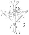
- Figure 2 is a partially hidden top plan view of the aircraft 100 of Figure 1 configured in accordance with an embodiment of the invention.
- the first fuselage portion 110 has a first cross-sectional area 210
- the second fuselage portion 120 has a second cross-sectional area 220 that is less than the first cross-sectional area 210
- the third fuselage portion 130 has a third cross-sectional area 230 that is greater than the second cross-sectional area 220. Accordingly, the cross-sectional area distribution of the fuselage 102 is reduced at the second fuselage portion 120 adjacent to the wing 150 to maintain a smooth and gradual cross-sectional area distribution for the aircraft 100 consistent with the area rule.
- the aircraft 100 includes an engine nacelle 260 fixedly attached to the wing 150.
- the engine nacelle 260 can house an engine 261 for providing thrust to the aircraft 100, and can include an air inlet 262 positioned forward of the engine 261 and an exhaust gas outlet 264 positioned aft of the engine 261.
- the wing 150 can include a leading edge region 252 and a trailing edge region 254.
- the air inlet 262 of the engine nacelle 260 is positioned aft of the leading edge region 252, and the exhaust gas outlet 264 is positioned aft of the trailing edge region 254.
- the engine nacelle 260 can have other positions on the aircraft 100.
- the air inlet 262 can be positioned forward of the leading edge region 252.
- the engine nacelle 260 can be fixedly attached to the fuselage 102.
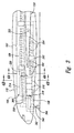
- Figure 3 is a partially hidden enlarged side elevation view of the first fuselage portion 110 showing the lower deck 108 configured in accordance with an embodiment of the invention.
- the lower deck 108 further includes a cargo portion 314 positioned forward of the second passenger portion 109.
- the cargo portion 314 can be configured to carry cargo containers 316, such as LD-3 cargo containers, or palletized cargo.
- The, first fuselage portion 110 can include a cargo door 318 positioned adjacent to the cargo portion 314 to allow the cargo containers 316 to be moved into and out of the cargo portion 314.
- the lower deck 108 further includes a separator 320 extending between the cargo portion 314 and the second passenger portion 109.
- the separator 320 can be a rigid or semi-rigid structure providing a barrier between the cargo portion 314 and the second passenger portion 109.
- the separator 320 can be a flexible structure, such as a cargo net.
- the separator 320 is selectively positionable at different longitudinal stations of the lower deck 108. In this way, the relative sizes of the cargo portion 314 and the second passenger portion 109 can be adjusted to accommodate different cargo and passenger loads.
- the longitudinal station of the separator 320 can be at least generally non-adjustable.
- the first fuselage portion 110 includes a first row of passenger windows 350 positioned adjacent to the upper deck 106, and a second row of passenger windows 352 positioned adjacent to the lower deck 108.
- the second row of passenger windows 352 extends only part of the way aft relative to the second passenger portion 109 because it is blocked by a portion of the wing 150, such as a forward portion of the wing or strake.
- the first fuselage portion 110 can include a row of simulated extemal-view windows 354 extending aft from the second row of passenger windows 352 adjacent to the wing 150.
- the simulated extemal-view windows 354 can include "virtual window technology" such as video displays that simulate conventional extemal-view windows and provide passengers seated adjacent to the wing 150 with a simulated view out of the second passenger portion 109. In other embodiments, the simulated external-view windows 354 can be omitted.
- the first fuselage portion 110 includes a stairway 322 extending between the upper deck 106 and the lower deck 108 to accommodate passenger travel between the first passenger portion 107 and the second passenger portion 109.
- the first fuselage portion 110 can include other types of passageways for passenger travel between the upper deck 106 and the lower deck 108.
- the first fuselage portion 110 can include an elevator.
- the first fuselage portion can include an escalator or a ladder.
- the first fuselage portion 110 can also include a passenger door 353 providing passengers with an additional way to enter or exit the second passenger portion 109. In certain embodiments, the passenger door 353 can be used as an emergency exit.
- the first fuselage portion 110 includes an aft-retracting landing gear 360 housed in a wheel well 366 positioned forward of the lower deck 108.
- the landing gear 360 can pivot rearwardly and upwardly about a trunnion 362 to move a nosewheel or wheel truck 364 from a static deployed position (shown in Figure 3) to a static retracted position within the wheel well 366.
- Positioning the trunnion 362 in a forward portion of the wheel well 366 can cause the landing gear 360 to collapse into the wheel well 366 in the event of a landing gear collapse, thus avoiding damage to the lower deck 108.
- the landing gear 360 can retract in other directions.
- the landing gear 360 can retract forward into an appropriately configured wheel well.
- the landing gear 360 can retract sideways into an appropriately configured wheel well.
- One feature of embodiments of the invention shown in Figures 1-3 is that the second passenger portion 109 is positioned in the first fuselage portion 110 and, as a result, the first fuselage portion 110 requires additional cross-sectional area to provide the necessary standing height.
- One advantage of this feature is that the additional cross-sectional area can be efficiently utilized to provide the aircraft 100 with a generally smooth and gradual cross-sectional area distribution for reducing wave drag at transonic speeds in accordance with the area rule.
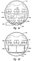
- Figures 4A-B are enlarged cross-sectional elevation views of the first fuselage portion 110 configured in accordance with embodiments of the invention and taken substantially along lines 4A-4A and 4B-4B in Figure 3, respectively.
- the second passenger portion 109 includes a first passenger seat section 410a and a second passenger seat section 410b positioned on opposite sides of a central passenger aisle 412.
- each passenger seat section 410a, b includes three-abreast passenger seating.
- the second passenger portion 109 can include other passenger seat arrangements.
- the passenger aisle 412 can be positioned off-center and the second passenger portion 109 can include two-abreast passenger seating on one side of the passenger aisle 412 and three-abreast passenger seating on the other.
- the second passenger portion 109 can include two passenger aisles separating three passenger seat sections.
- each passenger seat section can include one- or two-abreast passenger seating.
- the second passenger portion 109 can include still other passenger seat arrangements depending on factors such as fuselage, aisle and/or seat width, or class of service.
- the second passenger portion 109 includes a first floor 414a positioned above an energy-absorbing structure 470.
- the energy-absorbing structure 470 can be configured to absorb the energy from an impact to the bottom of the first fuselage portion 110 for protection of the passengers seated in the second passenger portion 109. Such an impact could occur, for example, during a crash landing.
- the energy absorbing structure 470 can include energy-absorbing compressible materials, such as aluminum honeycomb.
- the energy-absorbing structure can include additional fuselage frame members. In other embodiments, other types of energy-absorbing structure can be included.
- the first floor 414a can be spaced apart from the bottom of the first fuselage portion 110 by a distance 462, and the distance 462 can be equal to about 30 inches. In other embodiments, the distance 462 can have other values. For example, in another embodiment, the distance 462 can be greater than 30 inches, for example, about 36 inches. In a further embodiment, the distance 462 can be about 24 inches. In still other embodiments, the distance 462 can have other values depending on factors such as the energy-absorbing capability of the energy-absorbing structure 470 or the applicable regulations.
- the cargo portion 314 is configured to carry standard Unit Load Devices ("ULDs"), such as LD-3 cargo containers 416a and 416b, in a two-abreast arrangement.
- ULDs Unit Load Devices
- the cargo portion 314 can be configured to carry other types of containerized cargo.
- the cargo portion 314 can be configured to carry LD-2 or LD-1 cargo containers in two-abreast or other arrangements.
- the cargo portion 314 can be configured to carry palletized cargo or palletized cargo and standard ULDs.
- the cargo portion 314 can include a second floor 414b positioned above the first floor 414a, if required to accommodate the cargo containers 416a and 416b.
- the second floor 414b can include floor inserts 418 removably installed across the lower deck 108. Accordingly, use of the removable floor inserts 418 and the movable separator 320 ( Figure 3) may singly or in combination enable the lower deck 108 to be selectively configured to carry cargo, passengers, or cargo and passengers in different proportions.
- Figure 5 is a partially hidden enlarged side elevation view of the first fuselage portion 110 with the lower deck 108 configured in accordance with another embodiment of the invention.
- one or more of the removable floor inserts 418 have been installed in the lower deck 108 to extend the cargo portion 314 further aft as compared to the embodiment shown in Figure 3.
- the movable separator 320 has also been positioned further aft to separate the extended cargo portion 314 from the reduced second passenger portion 109.
- the cargo portion 314 is configured to carry six pairs of containerized cargo, such as six pairs of LD-3 cargo containers 416.
- the relative sizes of the cargo portion 314 and the second passenger portion 109 can be adjusted differently depending on other factors, such as the relative demand for cargo capacity versus passenger capacity.
Landscapes
- Engineering & Computer Science (AREA)
- Aviation & Aerospace Engineering (AREA)
- Mechanical Engineering (AREA)
- Physics & Mathematics (AREA)
- Fluid Mechanics (AREA)
- Escalators And Moving Walkways (AREA)
- Tires In General (AREA)
- Automatic Assembly (AREA)
- Body Structure For Vehicles (AREA)
Description
- The following disclosure relates generally to multideck aircraft and, more particularly, to transonic aircraft having multipurpose lower decks for carrying passengers or passengers and cargo.
- Conventional transport aircraft typically include a passenger cabin on an upper deck and a cargo hold on a lower deck. This configuration allows airlines to generate revenue by transporting both passengers and cargo over selected routes. On some routes, however, there is a greater demand for transporting passengers than cargo. On these routes, the airlines may accordingly prefer to use some of the space on the lower cargo deck for additional passenger seating.
- One problem with adding passenger seating, sleeping cabins, or other passenger service facilities to lower decks is that lower decks typically provide insufficient standing height. One attempt to overcome this problem is disclosed-in U.S. Patent No. 5,752,673 to Schliwa et al ("Schliwa"). Schliwa discloses lowering the floor in an aisle section of the lower deck to provide at least enough clearance for a standing person of normal height.
- Another problem with using lower cargo decks for passengers is providing sufficient structure beneath the lower decks to protect the passengers in the event of a crash landing. Regulations could require at least 30 inches of compressible structure beneath the lower deck if the lower deck is to be used to carry passengers. Lowering the floor of the lower deck as proposed by Schliwa compounds this problem because it further reduces the space beneath the lower deck.
- One approach to meet the compressible structure requirement is disclosed in U.S. Patent No. 5,542,626 to Beuck et al (" Beuck"). Beuck discloses an energy absorbing structural unit that is attached to the underside of an aircraft fuselage. The structural unit proposed by Beuck is an add-on feature of considerate size that extends downwardly and outwardly around the lower half of the fuselage cross-section to protect a lower passenger deck in the event of an impact. Because of its size and complexity, implementing the Beuck approach may add considerable cost, weight and aerodynamic drag to an aircraft.
- US-A-5992797 , which is regarded as the closest prior art, discloses a subsonic aircraft having the main and upper passenger seating decks both above the wing
- Aspects of the invention are directed to aircraft, such as transonic aircraft, having multipurpose lower decks usable for transporting passengers; cargo, or passengers and cargo. In one aspect, an aircraft according to
claim 1 includes a first fuselage portion and a second fuselage portion positioned aft of the first fuselage portion. The first fuselage portion can have a first dimension at least approximately parallel to a yaw axis, and the second fuselage portion can have a second dimension at least approximately parallel to the yaw axis that is less than the first dimension. The aircraft fuselage can further include a first deck and a second deck. The first deck can extend at least within the first and second fuselage portions, and can have a first passenger portion configured to accommodate passengers. The second deck can extend at least within the first fuselage portion, and can have a second passenger portion configured to accommodate passengers. In another aspect, the second deck can further include a cargo portion configured to carry cargo containers. - In a further aspect of the invention, the aircraft fuselage can also include a third fuselage portion positioned aft of the second fuselage portion. The third fuselage portion can have a third dimension at least approximately parallel to the yaw axis that is greater than the second dimension. The first deck can extend within the third fuselage portion.
- In still another aspect of the invention, a method for manufacturing an aircraft includes providing a first fuselage portion and attaching a second fuselage portion to the first fuselage portion aft of the first fuselage portion. The first fuselage portion can have a first dimension at least approximately parallel to a yaw axis, and the second fuselage portion can have a second dimension at least approximately parallel to the yaw axis that is less than the first dimension. The method can further include positioning a wing at least proximate to the second fuselage portion, extending at least generally outboard relative to the second fuselage portion. The method can additionally include positioning a first deck at least within the first and second fuselage portions, and positioning a second deck at least within the first fuselage portion. The first deck can include a first passenger portion configured to accommodate passengers, and the second deck can include a second passenger portion configured to accommodate passengers.
-
- Figure 1 is a partially hidden side elevation view of an aircraft having a lower deck configured in accordance with an embodiment of the invention.
- Figure 2 is a partially hidden top plan view of the aircraft of Figure 1 configured in accordance with an embodiment of the invention.
- Figure 3 is a partially hidden enlarged side elevation view of a forward portion of the fuselage shown in Figures 1 and 2 configured in accordance with an embodiment of the invention.
- Figures 4A-B are enlarged cross-sectional elevation views of the forward fuselage portion of Figure 3 configured in accordance with embodiments of the invention and taken substantially along
lines 4A-4A and 4B-4B in Figure 3, respectively. - Figure 5 is a partially hidden enlarged side elevation view of the forward fuselage portion shown in Figures 1-3 configured in accordance with another embodiment of the invention.
- The following disclosure describes transport aircraft, such as transonic transport aircraft; having lower decks configured to carry passengers or passengers and cargo. Certain specific details are set forth in the following description and in Figures 1-5 to provide a thorough understanding of various embodiments of the invention. Details of well-known structures and systems often associated with aircraft are not set forth in the following disclosure, however, to avoid unnecessarily obscuring the various embodiments of the invention. Further, those of ordinary skill in the art will understand that they can practice other embodiments of the invention without several of the details described below.
- In the drawings, identical reference numbers identify identical or at least generally similar elements. To facilitate the discussion of any particular element, the most significant digit or digits of any reference number refer to the figure in which that element is first introduced. For example,
element 110 is first introduced and discussed with reference to Figure 1. - Figure 1 is a partially hidden side elevation view of an
aircraft 100 having afuselage 102 with a multipurposelower deck 108 configured in accordance with an embodiment of the invention. In one aspect of this embodiment, thefuselage 102 includes afirst fuselage portion 110 and asecond fuselage portion 120 positioned aft of thefirst fuselage portion 110. Thesecond fuselage portion 120 can be positioned at least proximate to awing 150. Thefuselage 102 can further include athird fuselage portion 130 positioned aft of thesecond fuselage portion 120, and anempennage portion 140 positioned aft of thethird fuselage portion 130. Theempennage portion 140 can include avertical stabilizer 142 for controlling motion of theaircraft 100 about ayaw axis 104 in flight. - In another aspect of this embodiment, the
fuselage 102 is an "area-ruled" fuselage configured to reduce transonic wave drag. For example, thefirst fuselage portion 110 can have afirst dimension 111 at least approximately parallel to theyaw axis 104, thesecond fuselage portion 120 can have asecond dimension 112 at least approximately parallel to theyaw axis 104 and less than thefirst dimension 111, and thethird fuselage portion 130 can have athird dimension 113 at least approximately parallel to theyaw axis 104 and greater than thesecond dimension 112. In this manner, the illustrated fuselage vertical area-ruling contributes to the overall cross-sectional area-ruling of the fuselage which can reduce transonic wave drag. - In a further aspect of this embodiment, the
fuselage 102 includes anupper deck 106 having afirst passenger portion 107 configured to accommodate passengers (not shown). Theupper deck 106 can extend within thefirst fuselage portion 110, thesecond fuselage portion 120, and thethird fuselage portion 130. The multipurpose lower deck 108 (or "lower deck 108") can be positioned at least within thefirst fuselage portion 110 beneath theupper deck 106, and can include asecond passenger portion 109 configured to accommodate passengers. Accordingly, thelower deck 108 is positioned in the portion of thefuselage 102 that, by virtue of the area rule, has additional space available to accommodate thesecond passenger portion 109. In other embodiments, thelower deck 108 can extend beyond thefirst fuselage portion 110, for example, at least partially into thesecond fuselage portion 120. - Figure 2 is a partially hidden top plan view of the
aircraft 100 of Figure 1 configured in accordance with an embodiment of the invention. In one aspect of this embodiment, thefirst fuselage portion 110 has afirst cross-sectional area 210, thesecond fuselage portion 120 has asecond cross-sectional area 220 that is less than thefirst cross-sectional area 210, and thethird fuselage portion 130 has a thirdcross-sectional area 230 that is greater than thesecond cross-sectional area 220. Accordingly, the cross-sectional area distribution of thefuselage 102 is reduced at thesecond fuselage portion 120 adjacent to thewing 150 to maintain a smooth and gradual cross-sectional area distribution for theaircraft 100 consistent with the area rule. - In another aspect of this embodiment, the
aircraft 100 includes anengine nacelle 260 fixedly attached to thewing 150. Theengine nacelle 260 can house anengine 261 for providing thrust to theaircraft 100, and can include anair inlet 262 positioned forward of theengine 261 and anexhaust gas outlet 264 positioned aft of theengine 261. Thewing 150 can include a leadingedge region 252 and atrailing edge region 254. In a further aspect of this embodiment, theair inlet 262 of theengine nacelle 260 is positioned aft of the leadingedge region 252, and theexhaust gas outlet 264 is positioned aft of thetrailing edge region 254. In other embodiments, theengine nacelle 260 can have other positions on theaircraft 100. For example, in another embodiment, theair inlet 262 can be positioned forward of theleading edge region 252. In a further embodiment, theengine nacelle 260 can be fixedly attached to thefuselage 102. - Figure 3 is a partially hidden enlarged side elevation view of the
first fuselage portion 110 showing thelower deck 108 configured in accordance with an embodiment of the invention. In one aspect of this embodiment, thelower deck 108 further includes acargo portion 314 positioned forward of thesecond passenger portion 109. Thecargo portion 314 can be configured to carrycargo containers 316, such as LD-3 cargo containers, or palletized cargo. The,first fuselage portion 110 can include acargo door 318 positioned adjacent to thecargo portion 314 to allow thecargo containers 316 to be moved into and out of thecargo portion 314. - In another aspect of this embodiment, the
lower deck 108 further includes aseparator 320 extending between thecargo portion 314 and thesecond passenger portion 109. Theseparator 320 can be a rigid or semi-rigid structure providing a barrier between thecargo portion 314 and thesecond passenger portion 109. In other embodiments, theseparator 320 can be a flexible structure, such as a cargo net. In a further aspect of this embodiment, theseparator 320 is selectively positionable at different longitudinal stations of thelower deck 108. In this way, the relative sizes of thecargo portion 314 and thesecond passenger portion 109 can be adjusted to accommodate different cargo and passenger loads. In other embodiments, the longitudinal station of theseparator 320 can be at least generally non-adjustable. - In yet another aspect of this embodiment, the
first fuselage portion 110 includes a first row ofpassenger windows 350 positioned adjacent to theupper deck 106, and a second row ofpassenger windows 352 positioned adjacent to thelower deck 108. The second row ofpassenger windows 352 extends only part of the way aft relative to thesecond passenger portion 109 because it is blocked by a portion of thewing 150, such as a forward portion of the wing or strake. To provide the passengers seated next to thewing 150 with a view out of theaircraft 100, thefirst fuselage portion 110 can include a row of simulated extemal-view windows 354 extending aft from the second row ofpassenger windows 352 adjacent to thewing 150. The simulated extemal-view windows 354 can include "virtual window technology" such as video displays that simulate conventional extemal-view windows and provide passengers seated adjacent to thewing 150 with a simulated view out of thesecond passenger portion 109. In other embodiments, the simulated external-view windows 354 can be omitted. - In a further aspect of this embodiment, the
first fuselage portion 110 includes astairway 322 extending between theupper deck 106 and thelower deck 108 to accommodate passenger travel between thefirst passenger portion 107 and thesecond passenger portion 109. In other embodiments, thefirst fuselage portion 110 can include other types of passageways for passenger travel between theupper deck 106 and thelower deck 108. For example, in another embodiment, thefirst fuselage portion 110 can include an elevator. In further embodiments, the first fuselage portion can include an escalator or a ladder. Thefirst fuselage portion 110 can also include apassenger door 353 providing passengers with an additional way to enter or exit thesecond passenger portion 109. In certain embodiments, thepassenger door 353 can be used as an emergency exit. - In still another aspect of this embodiment, the
first fuselage portion 110 includes an aft-retractinglanding gear 360 housed in a wheel well 366 positioned forward of thelower deck 108. After takeoff, thelanding gear 360 can pivot rearwardly and upwardly about atrunnion 362 to move a nosewheel orwheel truck 364 from a static deployed position (shown in Figure 3) to a static retracted position within the wheel well 366. Positioning thetrunnion 362 in a forward portion of the wheel well 366 can cause thelanding gear 360 to collapse into the wheel well 366 in the event of a landing gear collapse, thus avoiding damage to thelower deck 108. In other embodiments, however, thelanding gear 360 can retract in other directions. For example, in another embodiment, thelanding gear 360 can retract forward into an appropriately configured wheel well. In a further embodiment, thelanding gear 360 can retract sideways into an appropriately configured wheel well. - One feature of embodiments of the invention shown in Figures 1-3 is that the
second passenger portion 109 is positioned in thefirst fuselage portion 110 and, as a result, thefirst fuselage portion 110 requires additional cross-sectional area to provide the necessary standing height. One advantage of this feature is that the additional cross-sectional area can be efficiently utilized to provide theaircraft 100 with a generally smooth and gradual cross-sectional area distribution for reducing wave drag at transonic speeds in accordance with the area rule. - Figures 4A-B are enlarged cross-sectional elevation views of the
first fuselage portion 110 configured in accordance with embodiments of the invention and taken substantially alonglines 4A-4A and 4B-4B in Figure 3, respectively. Referring first to Figure 4A, in one aspect of this embodiment, thesecond passenger portion 109 includes a first passenger seat section 410a and a secondpassenger seat section 410b positioned on opposite sides of acentral passenger aisle 412. In the illustrated embodiment, each passenger seat section 410a, b includes three-abreast passenger seating. In other embodiments, thesecond passenger portion 109 can include other passenger seat arrangements. For example, in another embodiment, thepassenger aisle 412 can be positioned off-center and thesecond passenger portion 109 can include two-abreast passenger seating on one side of thepassenger aisle 412 and three-abreast passenger seating on the other. In a further embodiment, thesecond passenger portion 109 can include two passenger aisles separating three passenger seat sections. In this further embodiment, each passenger seat section can include one- or two-abreast passenger seating. In still other embodiments, thesecond passenger portion 109 can include still other passenger seat arrangements depending on factors such as fuselage, aisle and/or seat width, or class of service. - In another aspect of this embodiment, the
second passenger portion 109 includes a first floor 414a positioned above an energy-absorbingstructure 470. The energy-absorbingstructure 470 can be configured to absorb the energy from an impact to the bottom of thefirst fuselage portion 110 for protection of the passengers seated in thesecond passenger portion 109. Such an impact could occur, for example, during a crash landing. In one embodiment, theenergy absorbing structure 470 can include energy-absorbing compressible materials, such as aluminum honeycomb. In another embodiment, the energy-absorbing structure can include additional fuselage frame members. In other embodiments, other types of energy-absorbing structure can be included. - In a further aspect of this embodiment, the first floor 414a can be spaced apart from the bottom of the
first fuselage portion 110 by adistance 462, and thedistance 462 can be equal to about 30 inches. In other embodiments, thedistance 462 can have other values. For example, in another embodiment, thedistance 462 can be greater than 30 inches, for example, about 36 inches. In a further embodiment, thedistance 462 can be about 24 inches. In still other embodiments, thedistance 462 can have other values depending on factors such as the energy-absorbing capability of the energy-absorbingstructure 470 or the applicable regulations. - Referring now to Figure 4B, in one aspect of this embodiment, the
cargo portion 314 is configured to carry standard Unit Load Devices ("ULDs"), such as LD-3cargo containers 416a and 416b, in a two-abreast arrangement. In other embodiments, thecargo portion 314 can be configured to carry other types of containerized cargo. For example, in another embodiment, thecargo portion 314 can be configured to carry LD-2 or LD-1 cargo containers in two-abreast or other arrangements. In further embodiments, thecargo portion 314 can be configured to carry palletized cargo or palletized cargo and standard ULDs. - In a further aspect of this embodiment, the
cargo portion 314 can include asecond floor 414b positioned above the first floor 414a, if required to accommodate thecargo containers 416a and 416b. Thesecond floor 414b can include floor inserts 418 removably installed across thelower deck 108. Accordingly, use of the removable floor inserts 418 and the movable separator 320 (Figure 3) may singly or in combination enable thelower deck 108 to be selectively configured to carry cargo, passengers, or cargo and passengers in different proportions. - Figure 5 is a partially hidden enlarged side elevation view of the
first fuselage portion 110 with thelower deck 108 configured in accordance with another embodiment of the invention. In one aspect of this embodiment, one or more of the removable floor inserts 418 have been installed in thelower deck 108 to extend thecargo portion 314 further aft as compared to the embodiment shown in Figure 3. In addition, themovable separator 320 has also been positioned further aft to separate theextended cargo portion 314 from the reducedsecond passenger portion 109. Accordingly, in this embodiment thecargo portion 314 is configured to carry six pairs of containerized cargo, such as six pairs of LD-3cargo containers 416. In other embodiments, the relative sizes of thecargo portion 314 and thesecond passenger portion 109 can be adjusted differently depending on other factors, such as the relative demand for cargo capacity versus passenger capacity. - From the foregoing, it will be appreciated that specific embodiments of the invention have been described herein for purposes of illustration, but that various modifications may be made without deviating from the scope of the invention. For example, although selected embodiments have been described above in the context of mid-wing aircraft, the present invention is equally applicable to aft-wing aircraft, such as delta-wing aircraft having a small forward wing or canard. Accordingly, the invention is not limited except as by the appended claims.
Claims (25)
- An aircraft having:- a yaw axis;- a wing (150);- a first fuselage portion (110) with a first dimension at least approximately parallel to the yaw axis;- a second fuselage portion (120) positioned aft of the first fuselage portion, the second fuselage portion having a seond dimension at least approximately parallel to the yaw axis, the second dimension being less that the first dimension;- a first deck (106) extending at least within the first and second fuselage portions and above the wing, the first deck including a first passenger portion (107) configured to accommodate passengers; and- a second deck (108) positioned below the first deck and below the wing, the second deck extending within the first fuselage portion only, the second deck including a second passenger portion (109) configured to accommodate passengers.
- The aircraft of claim 1, further comprising a third fuselage portion (130) positioned aft of the second fuselage portion and having a third dimension at least approximately parallel to the yaw axis, the third dimension being greater than the second dimension, wherein the first deck extends within the third fuselage portion.
- The aircraft of claim 2, wherein the first fuselage portion has a first cross-sectional area, the second fuselage portion has a second cross-sectional area less than the first cross-sectional area, and the third fuselage portion has a third cross-sectional area greater than the second cross-sectional area.
- The aircraft of any of claims 1-3 wherein the second deck further includes a cargo portion (314) configured to carry cargo containers, and wherein the first fuselage portion further includes a cargo door positioned to move the cargo containers into and out of the cargo portion.
- The aircraft of claim 4 wherein the cargo portion is positioned forward of the second passenger portion.
- The aircraft of claim 4 or 5 wherein the cargo portion is configured to carry at least two LD-3 cargo containers, the cargo door being configured to allow the LD-3 cargo containers to be moved into and out of the cargo portion.
- The aircraft of claim 4, 5 or 6 wherein the second deck further includes a separator (320) positioned between the cargo portion and the second passenger portion to provide a physical barrier between the cargo portion and the second passenger portion.
- The aircraft of claim 4, 5 or 6 wherein the second deck further includes a movable separator positioned between the cargo portion and the second passenger portion, wherein the movable separator is selectively positionable between at least a first longitudinal station and a second longitudinal station to adjust the relative sizes of the cargo portion and the second passenger portion.
- The aircraft of any of claims 1-8 wherein the first fuselage portion further includes a first row of windows (350) positioned at least proximate to the first passenger portion and a second row of windows (352) positioned at least proximate to the second passenger portion.
- The aircraft of any of claims 1-9 wherein the first fuselage portion further includes at least one simulated external-view window (354) positioned at least proximate to the second passenger portion.
- The aircraft of any of claims 1-10 wherein the second passenger portion includes first and second passenger seat sections positioned on opposite sides of a central passenger aisle.
- The aircraft of any of claims 1-11 wherein the second passenger portion includes first and second passenger aisles separating first, second and third passenger seat sections.
- The aircraft of any of claims 1-12, further comprising a passageway extending between the first and second decks to accommodate passenger travel between the first and second decks.
- The aircraft of claim 13 wherein the passageway includes an elevator.
- The aircraft of any of claims 1-14 wherein the second passenger portion includes a first floor, and wherein the second deck further includes a cargo portion having a second floor, the second floor being vertically offset from the first floor.
- The aircraft of any of claims 1-15 wherein at least a region of the second passenger portion is optionally configurable as a cargo portion configured to carry cargo containers.
- The aircraft of claim 16 wherein the region of the second passenger portion optionally configurable as the cargo portion is configured to removably receive floor inserts (418) to support the cargo containers.
- The aircraft of any of claims 1-17 wherein the first fuselage portion further includes an energy-absorbing structure (470) positioned at least approximately beneath the second passenger portion, the energy-absorbing structure being configured to absorb the energy from an impact to the first fuselage portion from below the second passenger portion.
- The aircraft of claim 18 wherein the second passenger portion includes a passenger aisle, and the energy-absorbing structure extends to a depth of about 75 cm (30 inches) or more beneath the passenger aisle.
- The aircraft of any of claims 1-19, further comprising an aft-retracting nose landing gear (360) positioned forward of the second deck.
- The aircraft according to any of claims 1-20 wherein the first fuselage portion has a first cross-sectional area; and
wherein the second fuselage portion has a second cross-sectional area less than the first cross-sectional area. - The aircraft of claim 21 wherein the second fuselage portion is configured to support a wing, and wherein the aircraft fuselage further comprises an empennage portion (140) positioned aft of the third fuselage portion, the empennage portion configured to support at least one stabilizer surface (142) extending outwardly from the empennage portion.
- An aircraft according to any of claims 1-22, wherein the wing includes a leading edge region, and wherein the aircraft further comprises at least one engine nacelle (160) fixedly attached to the wing, the engine nacelle including an air inlet positioned aft of the leading edge region.
- The aircraft of claim 23 wherein the wing includes a trailing edge region, the engine nacelle including an exhaust gas outlet positioned aft of the trailing edge region.
- A method for manufacturing an aircraft having a yaw axis, the method comprising:- providing a first fuselage portion having a first dimension at least approximately parallel to the yaw axis;- attaching a second fuselage portion to the first fuselage portion aft of the first fuselage portion, the second fuselage portion having a second dimension at least approximately parallel to the yaw axis, the second dimension being less than the first dimension;- positioning a wing at least proximate to the second fuselage portion, the wing extending at least generally outboard from the second fuselage portion;- positioning a first deck at least within the first and second fuselage portions and above the wing, the first deck including a first passenger portion configured to accommodate passengers; and- positioning a second deck below the first deck and within the first fuselage portion only, the second deck including a second passenger portion configured to accommodate passengers.
Applications Claiming Priority (2)
| Application Number | Priority Date | Filing Date | Title |
|---|---|---|---|
| US278717 | 2002-10-22 | ||
| US10/278,717 US6772977B2 (en) | 2002-10-10 | 2002-10-22 | Aircraft with multipurpose lower decks and associated methods of manufacture |
Publications (3)
| Publication Number | Publication Date |
|---|---|
| EP1413513A2 EP1413513A2 (en) | 2004-04-28 |
| EP1413513A3 EP1413513A3 (en) | 2004-05-19 |
| EP1413513B1 true EP1413513B1 (en) | 2006-03-15 |
Family
ID=32069342
Family Applications (1)
| Application Number | Title | Priority Date | Filing Date |
|---|---|---|---|
| EP03078139A Expired - Lifetime EP1413513B1 (en) | 2002-10-22 | 2003-10-03 | Aircraft with multipurpose lower decks and associated methods of manufacture |
Country Status (3)
| Country | Link |
|---|---|
| US (1) | US6772977B2 (en) |
| EP (1) | EP1413513B1 (en) |
| DE (1) | DE60303996T2 (en) |
Cited By (1)
| Publication number | Priority date | Publication date | Assignee | Title |
|---|---|---|---|---|
| WO2022191839A1 (en) | 2021-03-10 | 2022-09-15 | Zsm Holdings Llc | Removable cargo floor systems and methods for cargo aircraft |
Families Citing this family (31)
| Publication number | Priority date | Publication date | Assignee | Title |
|---|---|---|---|---|
| US20060102785A1 (en) * | 2004-10-14 | 2006-05-18 | Butt Thomas J | Airplane seating arrangement |
| US7395989B2 (en) | 2004-12-20 | 2008-07-08 | Airbus | Aircraft fuselage and corresponding aircraft |
| FR2879560B1 (en) * | 2004-12-20 | 2008-06-20 | Airbus Sas | AIRCRAFT FUSELAGE AND AIRCRAFT CORRESPONDING |
| WO2007115804A1 (en) | 2006-04-10 | 2007-10-18 | Airbus Deutschland Gmbh | Aircraft fuselage with circular-arc-shaped exterior contour |
| DE102006016756A1 (en) * | 2006-04-10 | 2007-10-11 | Airbus Deutschland Gmbh | Aircraft fuselage has two exterior skin regions comprising circular-arc-shaped contour of uniform curvature, along longitudinal direction of aircraft passenger cabin |
| GB0609890D0 (en) * | 2006-05-18 | 2006-06-28 | Airbus Uk Ltd | Aircraft with improved cargo hold |
| GB0609888D0 (en) * | 2006-05-18 | 2006-06-28 | Airbus Sas | Aircraft cabin configuration |
| DE102006026169B4 (en) * | 2006-06-06 | 2012-06-21 | Airbus Operations Gmbh | Aircraft fuselage structure and method for its manufacture |
| DE102006026168A1 (en) * | 2006-06-06 | 2008-01-31 | Airbus Deutschland Gmbh | Aircraft fuselage structure and method for its manufacture |
| DE102006026170B4 (en) * | 2006-06-06 | 2012-06-21 | Airbus Operations Gmbh | Aircraft fuselage structure and method for its manufacture |
| FR2910434B1 (en) * | 2006-12-26 | 2009-12-04 | Airbus | AIRCRAFT FUSELAGE |
| US8899520B2 (en) | 2009-05-24 | 2014-12-02 | The Boeing Company | Mid-wing airplane |
| US9452817B1 (en) * | 2010-03-03 | 2016-09-27 | The Boeing Company | Aircraft having split level cabin floors |
| US10589836B2 (en) | 2010-03-03 | 2020-03-17 | The Boeing Company | Split level forward double deck airliner |
| US9108719B2 (en) * | 2010-03-03 | 2015-08-18 | The Boeing Company | Aircraft with AFT split-level multi-deck fusealge |
| US9187176B2 (en) | 2011-09-20 | 2015-11-17 | The Boeing Company | Dual boarding system for aircraft |
| FR2981634B1 (en) * | 2011-10-19 | 2014-10-24 | Airbus | AIRCRAFT CABIN FOR HOSTING PASSENGERS AT SEVERAL LEVELS AND CORRESPONDING AIRCRAFT |
| US8746616B2 (en) * | 2011-10-19 | 2014-06-10 | The Boeing Company | Mid-wing multi-deck airplane |
| RU2529309C2 (en) * | 2012-12-27 | 2014-09-27 | Российская Федерация, От Имени Которой Выступает Министерство Промышленности И Торговли Российской Федерации | Subsonic airliner |
| JP6333633B2 (en) | 2013-08-22 | 2018-05-30 | ザ・ボーイング・カンパニーThe Boeing Company | Aircraft with multi-deck fuselage on the mezzanine floor |
| EP2886447A1 (en) | 2013-12-18 | 2015-06-24 | Airbus Operations, S.L. | A double-deck airplane |
| JP2017516716A (en) * | 2014-05-30 | 2017-06-22 | ゾディアック エアロスペース | Lower deck commercial room |
| US10909397B2 (en) | 2014-06-13 | 2021-02-02 | B/E Aerospace, Inc. | Aircraft suite including main cabin compartment and lower lobe rest compartment |
| DE102017106411B4 (en) * | 2017-03-24 | 2022-05-12 | Airbus Operations Gmbh | Multifunctional container system for producing a container that can be used in an aircraft hold |
| US11136137B2 (en) | 2018-09-10 | 2021-10-05 | Rockwell Collins, Inc. | Non-intrusive passenger rest cabin monitoring system |
| US11167850B2 (en) | 2018-09-10 | 2021-11-09 | Rockwell Collins, Inc. | Passenger friendly overhead rest cabin configuration |
| US11447250B2 (en) | 2018-09-10 | 2022-09-20 | Rockwell Collins, Inc. | Optimized configuration for lower lobe passenger rest cabins |
| US11235852B2 (en) | 2018-09-10 | 2022-02-01 | B/E Aerospace, Inc. | Bidirectional hatch for passenger rest compartment |
| US20240109649A1 (en) * | 2022-10-03 | 2024-04-04 | Jetzero, Inc. | Aircraft with cabin-stowed landing gear |
| US12559230B2 (en) | 2024-01-18 | 2026-02-24 | Jetzero, Inc. | Blended wing body aircraft with landing gear aft of a rear spar |
| US12583585B2 (en) | 2024-01-22 | 2026-03-24 | Jetzero, Inc. | Blended wing body aircraft with rear engines |
Family Cites Families (16)
| Publication number | Priority date | Publication date | Assignee | Title |
|---|---|---|---|---|
| US2874922A (en) * | 1956-08-24 | 1959-02-24 | Richard T Whitcomb | Fuselage shaping to reduce the strength of shock waves about airplanes at transonic and supersonic speeds |
| DE3827279A1 (en) * | 1988-08-11 | 1990-02-15 | Messerschmitt Boelkow Blohm | DEVICE FOR INTERRUPTING LOADS |
| US4925132A (en) * | 1988-11-30 | 1990-05-15 | The Beta Group | Wide-body aircraft having efficient utilization of interior space and method therefor |
| FR2649665B1 (en) | 1989-07-12 | 1991-11-08 | Airbus Ind | LARGE CAPACITY FUSELAGE FOR AIRCRAFT |
| US6149101A (en) * | 1991-07-08 | 2000-11-21 | Tracy; Richard R. | Aircraft wing and fuselage contours |
| RU2040435C1 (en) * | 1992-07-14 | 1995-07-25 | Фатидин Абдурахманович Мухамедов | Large passenger-capacity aircraft of integrated system |
| US5529263A (en) * | 1992-10-21 | 1996-06-25 | The Boeing Company | Supersonic airplane with subsonic boost engine means and method of operating the same |
| DE4300877A1 (en) | 1993-01-15 | 1994-07-21 | Deutsche Aerospace Airbus | plane |
| DE4302706C2 (en) * | 1993-02-01 | 1996-04-18 | Daimler Benz Aerospace Airbus | Arrangement for handling food and beverages on board an aircraft |
| DE4313592C2 (en) | 1993-04-26 | 2000-02-17 | Daimler Chrysler Aerospace | Wide-body aircraft |
| DE4416506C2 (en) | 1994-05-10 | 1999-12-02 | Daimler Chrysler Aerospace | Passenger plane |
| US6152400A (en) * | 1997-09-10 | 2000-11-28 | The Boeing Company | Aircraft lower lobe sleeping compartment |
| EP0913325B1 (en) * | 1997-10-30 | 2004-06-09 | Ioannis Vassilios Constantopoulos | Passenger aircraft |
| US5992797A (en) | 1998-09-18 | 1999-11-30 | The Boeing Company | Dual upper deck airplane |
| US6575406B2 (en) * | 2001-01-19 | 2003-06-10 | The Boeing Company | Integrated and/or modular high-speed aircraft |
| US6478253B1 (en) * | 2001-04-20 | 2002-11-12 | The Boeing Company | Airframe having area-ruled fuselage keel |
-
2002
- 2002-10-22 US US10/278,717 patent/US6772977B2/en not_active Expired - Lifetime
-
2003
- 2003-10-03 EP EP03078139A patent/EP1413513B1/en not_active Expired - Lifetime
- 2003-10-03 DE DE60303996T patent/DE60303996T2/en not_active Expired - Lifetime
Cited By (3)
| Publication number | Priority date | Publication date | Assignee | Title |
|---|---|---|---|---|
| WO2022191839A1 (en) | 2021-03-10 | 2022-09-15 | Zsm Holdings Llc | Removable cargo floor systems and methods for cargo aircraft |
| EP4304936A4 (en) * | 2021-03-10 | 2024-12-25 | ZSM Holdings LLC | REMOVABLE CARGO FLOOR SYSTEMS AND METHODS FOR CARGO AIRCRAFT |
| US12312099B2 (en) | 2021-03-10 | 2025-05-27 | ZSM Holding, LLC | Removable cargo floor systems and methods for cargo aircraft |
Also Published As
| Publication number | Publication date |
|---|---|
| US6772977B2 (en) | 2004-08-10 |
| US20040075025A1 (en) | 2004-04-22 |
| DE60303996T2 (en) | 2006-09-07 |
| DE60303996D1 (en) | 2006-05-11 |
| EP1413513A3 (en) | 2004-05-19 |
| EP1413513A2 (en) | 2004-04-28 |
Similar Documents
| Publication | Publication Date | Title |
|---|---|---|
| US6772977B2 (en) | Aircraft with multipurpose lower decks and associated methods of manufacture | |
| US6857598B2 (en) | Integrated high-speed aircraft and associated methods of manufacture | |
| US9108719B2 (en) | Aircraft with AFT split-level multi-deck fusealge | |
| US8899520B2 (en) | Mid-wing airplane | |
| US9708065B2 (en) | Crown cabin configuration for an aircraft | |
| EP0987177B1 (en) | Dual upper deck airplane | |
| US6834833B2 (en) | Twin aisle small airplane | |
| EP2840023B1 (en) | Aircraft with aft split-level multi-deck fusealge | |
| CN100447049C (en) | Commercial aircraft with main deck and lower deck | |
| US8746616B2 (en) | Mid-wing multi-deck airplane | |
| EP1167183B1 (en) | Blended wing and multiple-body airplane configuration | |
| US7644888B2 (en) | High-speed aircraft and methods for their manufacture | |
| EP2404826B1 (en) | Amphibious large aircraft without airstairs | |
| US7419120B2 (en) | Triple-fuselage aircraft and families of aircraft of said type | |
| US20100187352A1 (en) | Multi deck aircraft | |
| CA2363194C (en) | Boarding device for aircraft and flying wings equipped with such a device | |
| US10589836B2 (en) | Split level forward double deck airliner | |
| EP1407963B1 (en) | Integrated high-speed aircraft and associated methods of manufacture | |
| US9452817B1 (en) | Aircraft having split level cabin floors | |
| EP3263457B1 (en) | Split level forward double deck airliner | |
| WO2013137915A1 (en) | Mid-wing airplane |
Legal Events
| Date | Code | Title | Description |
|---|---|---|---|
| PUAI | Public reference made under article 153(3) epc to a published international application that has entered the european phase |
Free format text: ORIGINAL CODE: 0009012 |
|
| PUAL | Search report despatched |
Free format text: ORIGINAL CODE: 0009013 |
|
| AK | Designated contracting states |
Kind code of ref document: A2 Designated state(s): AT BE BG CH CY CZ DE DK EE ES FI FR GB GR HU IE IT LI LU MC NL PT RO SE SI SK TR |
|
| AX | Request for extension of the european patent |
Extension state: AL LT LV MK |
|
| AK | Designated contracting states |
Kind code of ref document: A3 Designated state(s): AT BE BG CH CY CZ DE DK EE ES FI FR GB GR HU IE IT LI LU MC NL PT RO SE SI SK TR |
|
| AX | Request for extension of the european patent |
Extension state: AL LT LV MK |
|
| RIC1 | Information provided on ipc code assigned before grant |
Ipc: 7B 64D 11/00 B Ipc: 7B 64C 30/00 B Ipc: 7B 64C 1/00 A |
|
| 17P | Request for examination filed |
Effective date: 20041108 |
|
| AKX | Designation fees paid |
Designated state(s): DE FR GB |
|
| 17Q | First examination report despatched |
Effective date: 20050131 |
|
| GRAP | Despatch of communication of intention to grant a patent |
Free format text: ORIGINAL CODE: EPIDOSNIGR1 |
|
| GRAS | Grant fee paid |
Free format text: ORIGINAL CODE: EPIDOSNIGR3 |
|
| GRAA | (expected) grant |
Free format text: ORIGINAL CODE: 0009210 |
|
| AK | Designated contracting states |
Kind code of ref document: B1 Designated state(s): DE FR GB |
|
| REG | Reference to a national code |
Ref country code: GB Ref legal event code: FG4D |
|
| REF | Corresponds to: |
Ref document number: 60303996 Country of ref document: DE Date of ref document: 20060511 Kind code of ref document: P |
|
| ET | Fr: translation filed | ||
| PLBI | Opposition filed |
Free format text: ORIGINAL CODE: 0009260 |
|
| 26 | Opposition filed |
Opponent name: AIRBUS SAS/AIRBUS FRANCE SAS/AIRBUS UK LIMITED/ AI Effective date: 20061214 |
|
| PLAX | Notice of opposition and request to file observation + time limit sent |
Free format text: ORIGINAL CODE: EPIDOSNOBS2 |
|
| PLBB | Reply of patent proprietor to notice(s) of opposition received |
Free format text: ORIGINAL CODE: EPIDOSNOBS3 |
|
| PLCK | Communication despatched that opposition was rejected |
Free format text: ORIGINAL CODE: EPIDOSNREJ1 |
|
| PLBN | Opposition rejected |
Free format text: ORIGINAL CODE: 0009273 |
|
| STAA | Information on the status of an ep patent application or granted ep patent |
Free format text: STATUS: OPPOSITION REJECTED |
|
| 27O | Opposition rejected |
Effective date: 20091228 |
|
| REG | Reference to a national code |
Ref country code: FR Ref legal event code: PLFP Year of fee payment: 13 |
|
| REG | Reference to a national code |
Ref country code: FR Ref legal event code: PLFP Year of fee payment: 14 |
|
| REG | Reference to a national code |
Ref country code: FR Ref legal event code: PLFP Year of fee payment: 15 |
|
| REG | Reference to a national code |
Ref country code: FR Ref legal event code: PLFP Year of fee payment: 16 |
|
| PGFP | Annual fee paid to national office [announced via postgrant information from national office to epo] |
Ref country code: FR Payment date: 20221025 Year of fee payment: 20 |
|
| PGFP | Annual fee paid to national office [announced via postgrant information from national office to epo] |
Ref country code: GB Payment date: 20221027 Year of fee payment: 20 Ref country code: DE Payment date: 20221027 Year of fee payment: 20 |
|
| P01 | Opt-out of the competence of the unified patent court (upc) registered |
Effective date: 20230503 |
|
| REG | Reference to a national code |
Ref country code: DE Ref legal event code: R071 Ref document number: 60303996 Country of ref document: DE |
|
| REG | Reference to a national code |
Ref country code: GB Ref legal event code: PE20 Expiry date: 20231002 |
|
| PG25 | Lapsed in a contracting state [announced via postgrant information from national office to epo] |
Ref country code: GB Free format text: LAPSE BECAUSE OF EXPIRATION OF PROTECTION Effective date: 20231002 |