EP1413253B1 - Biopsathaltevorrichtung für eine Biopsiekanüle - Google Patents
Biopsathaltevorrichtung für eine Biopsiekanüle Download PDFInfo
- Publication number
- EP1413253B1 EP1413253B1 EP03011430A EP03011430A EP1413253B1 EP 1413253 B1 EP1413253 B1 EP 1413253B1 EP 03011430 A EP03011430 A EP 03011430A EP 03011430 A EP03011430 A EP 03011430A EP 1413253 B1 EP1413253 B1 EP 1413253B1
- Authority
- EP
- European Patent Office
- Prior art keywords
- biopsy
- wire
- cannula
- holding device
- material holding
- Prior art date
- Legal status (The legal status is an assumption and is not a legal conclusion. Google has not performed a legal analysis and makes no representation as to the accuracy of the status listed.)
- Expired - Lifetime
Links
- 239000000463 material Substances 0.000 claims abstract description 22
- 238000001574 biopsy Methods 0.000 claims description 156
- 210000001519 tissue Anatomy 0.000 claims description 38
- 210000001185 bone marrow Anatomy 0.000 claims description 9
- 238000003780 insertion Methods 0.000 claims description 5
- 230000037431 insertion Effects 0.000 claims description 5
- 210000000988 bone and bone Anatomy 0.000 abstract description 4
- 239000000126 substance Substances 0.000 abstract 2
- 230000001154 acute effect Effects 0.000 abstract 1
- 230000006378 damage Effects 0.000 description 3
- 208000027418 Wounds and injury Diseases 0.000 description 2
- 230000000694 effects Effects 0.000 description 2
- 208000014674 injury Diseases 0.000 description 2
- 230000036316 preload Effects 0.000 description 2
- 238000007796 conventional method Methods 0.000 description 1
- 238000006073 displacement reaction Methods 0.000 description 1
- 238000000605 extraction Methods 0.000 description 1
- 239000004744 fabric Substances 0.000 description 1
- 238000000034 method Methods 0.000 description 1
- 230000035515 penetration Effects 0.000 description 1
- 230000003716 rejuvenation Effects 0.000 description 1
- 238000010008 shearing Methods 0.000 description 1
- 239000007787 solid Substances 0.000 description 1
- 230000000451 tissue damage Effects 0.000 description 1
- 231100000827 tissue damage Toxicity 0.000 description 1
Images


Classifications
-
- A—HUMAN NECESSITIES
- A61—MEDICAL OR VETERINARY SCIENCE; HYGIENE
- A61B—DIAGNOSIS; SURGERY; IDENTIFICATION
- A61B10/00—Instruments for taking body samples for diagnostic purposes; Other methods or instruments for diagnosis, e.g. for vaccination diagnosis, sex determination or ovulation-period determination; Throat striking implements
- A61B10/02—Instruments for taking cell samples or for biopsy
- A61B10/0233—Pointed or sharp biopsy instruments
- A61B10/025—Pointed or sharp biopsy instruments for taking bone, bone marrow or cartilage samples
-
- A—HUMAN NECESSITIES
- A61—MEDICAL OR VETERINARY SCIENCE; HYGIENE
- A61B—DIAGNOSIS; SURGERY; IDENTIFICATION
- A61B10/00—Instruments for taking body samples for diagnostic purposes; Other methods or instruments for diagnosis, e.g. for vaccination diagnosis, sex determination or ovulation-period determination; Throat striking implements
- A61B10/02—Instruments for taking cell samples or for biopsy
- A61B10/0233—Pointed or sharp biopsy instruments
- A61B10/0266—Pointed or sharp biopsy instruments means for severing sample
-
- A—HUMAN NECESSITIES
- A61—MEDICAL OR VETERINARY SCIENCE; HYGIENE
- A61B—DIAGNOSIS; SURGERY; IDENTIFICATION
- A61B10/00—Instruments for taking body samples for diagnostic purposes; Other methods or instruments for diagnosis, e.g. for vaccination diagnosis, sex determination or ovulation-period determination; Throat striking implements
- A61B10/02—Instruments for taking cell samples or for biopsy
- A61B10/0233—Pointed or sharp biopsy instruments
- A61B10/025—Pointed or sharp biopsy instruments for taking bone, bone marrow or cartilage samples
- A61B2010/0258—Marrow samples
-
- A—HUMAN NECESSITIES
- A61—MEDICAL OR VETERINARY SCIENCE; HYGIENE
- A61B—DIAGNOSIS; SURGERY; IDENTIFICATION
- A61B17/00—Surgical instruments, devices or methods
- A61B17/32—Surgical cutting instruments
- A61B2017/320064—Surgical cutting instruments with tissue or sample retaining means
Definitions
- the invention relates to a biopsy holder for a biopsy cannula to perform transcutaneously Biopsies of tissue, especially hard tissue and bone marrow tissue, with one in the proximal one Insertable end of the biopsy cannula Biopsathaltevorraum, which between the Inner wall of the biopsy cannula and the withdrawing Tissue cylinder is inserted.
- Both conventional method is for this purpose the Handle the needle vibrated in the a plane perpendicular to the needle axis, wherein at the entry point into the tissue a trocar is provided.
- the consequence of this treatment is a Break of the connections between the distal end of the Biopsy and the remaining tissue at height of the distal end of the needle, which are pulled out can and in its interior the bioptic material contains, which by the rejuvenation at the end of the Needle is held.
- This examination method has the following disadvantages.
- the Movements or vibrations acting on the needle exercise to resolve the biopsy effect often smaller fractures on the surface and Interruptions in the cohesion of the hard tissue, in which the needle has been introduced, wherein the Possibility with the distance from the surface of the Tissue gradually grows. This is in pain for the patient and damage the needle, which tends to bend so that it is theirs necessary straightness loses.
- a patent DE 43 05 226 “device for needles for transcutaneous biopsies”
- an additional device for the conventional Biopsy needles for transcutaneous biopsy of tissue, especially hard tissue and bone marrow tissue, given is.
- the additional device allows the trouble-free execution of biopsy on any tissue, from hard, compact bones all the way to very thin and brittle bone marrow tissue without There is a risk that the biopsy needle without Tissue sample is pulled out.
- the additional device reduces the risk of tissue damage during the biopsy, causing pain to the patient reduced.
- the basic principle of the accessory device is that an insertable structure at the proximal end of the biopsy needle is inserted and between the inner wall of the needle and the Inserting tissue cylinder.
- US 5,333,619 discloses a biopsy holder according to the preamble of claim 1.
- the invention is based on the object, a Biopsy holder for the biopsy cannula for Performing transcutaneous biopsies of tissue, especially hard tissue and Bone marrow tissue, with the disadvantage of Prior art is overcome and a removal of the biopsy about the biopsy cannula with extreme small squeezing artifacts is feasible and a It is a guarantee that a removal of a Biopsies via the biopsy cannula is guaranteed.
- the object is achieved in that a biopsy holder for a biopsy cannula for performing transcutaneous biopsies of tissue, especially hard tissue and Bone marrow tissue, is realized, wherein the Claim 1 with its subclaims as technical solution is executed.
- a Biopsathaltevoriques in the form of a Grip and one arranged on the handle Wire executed.
- the handle is in any case the handle of the biopsy cannula lockable.
- the Wire is at its distal end with a connector executed, being ensured that the wire at the distal end of the biopsy cannula on the inner wall the biopsy cannula and a biopsy cylinder is available.
- the wire is with one Preload angle centered on the handle, where the bias angle is between 1 and 90 ° given is.
- On the wire and the given tip with bevel is a bevel angle of 5 to 85 °, advantageously 20 °, useful.
- the wire with the bevel designed so that the beveled directed towards the extracting Biopsatzylinder.
- the bevel can also be made with a hollow or be designed a bulbous cut. Essential is that the wire has a length which is sufficient to make an appropriate biopsy to remove the biopsy cannula.
- a Shank is arranged on the handle. It is the Shaft over the handle in the biopsy cannula on introduced proximal end of the biopsy cannula. At This shaft is at the distal end with a wire arranged a defined bias angle.
- a handle which after Introduction to the biopsy cannula lockable with the Handle of the biopsy cannula is executed.
- the Wire at the distal end of the shaft is in one firm connection with a corresponding Pretension angle between 1 ° to 90 ° depending on Application case arranged tolerating.
- the wire has a tip with a at its distal end Beveled, with the bevel depending on Application also from 5 ° to 85 °, advantageously 20 °, is present and the Beveled is given so that he goes to the Biopsy cylinder of the biopsy to be taken is directed.
- the length of the shaft and the associated wire is defined so that advantageously the wire in its length about 25 mm.
- the relation of the order of magnitude has to be be observed so that the shaft in the Introduction to the biopsy cannula of known type Has length that he immediately at the end of Biopsy cannula between the inner wall of the Biopsy cannula and biopsy ends.
- the wire which on is fixed to the shaft is advantageously with a roughened surface given.
- the profile of the wire is variable designed.
- the cross section of the wire is like that executed that in the fixation of the shaft in the biopsy cannula minimal squeezing artifacts between the inner wall of the biopsy cannula and the internal Biopsatzylinder arise.
- the diameter of the wire about 0.35 mm.
- the shaft reduced with the existing at the distal end wire the danger of injury to the tissue during biopsy, which reduces patient pain.
- the biopsy cannula becomes mechanical less stressed because bends are avoided which prolongs the life of the biopsy cannula becomes.
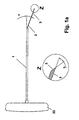
- FIG. 1b shows a device according to the invention in FIG the way that a lockable in the handle 20 Handle 22 is present.
- On the handle 22 is in the middle a wire 3 with a bias angle 2 given.
- the length of the wire 3 is designed that essentially the immediate end of the Biopsy cannula 4 is achieved.
- On the Bias angle 2 is given that sliding of the wire 3 on the inner wall of the biopsy cannula. 4 is performed between the Biopsatzylinder 6.
- the Bevel 5 of the wire 3 is designed in the manner that the bevel 5 towards the Biopsatzylinder 6th is given and thus an optimal displacement of the Biopatzylinders 6 at the introduction of the wire. 3 between the inner wall of the biopsy cannula 4 and the Biopatzylinders 6 is possible.
- FIG. 1a shows a shaft 1 with at the proximal end arranged handle 22 and at the distal end existing wire 3 with a corresponding Preload angle 2.
- the shaft 1 is arranged that he fits in the biopsy cannula 4 according to Figure 2 is inserted. It is important to mention that the handle 22 of the shaft 1 fixed lockable in the handle 20 of the biopsy cannula 4 after Introduction of the shaft 1 is executed.
- a wire 3 with a length given by 25 mm.
- the Angle of the bevel B is designed so that he between 5 ° to 85 °, preferably in the Embodiment, the polished section B is about 20 °.
- the bevel 5 is given so that he at Introduction of the shaft 1 into the biopsy cannula 4 between the Biopsatzylinder 6 and the inner wall of Biopsy cannula 4 towards the biopsy cylinder 6 is aligned.
- the bias angle 2, which defines the arrangement of the wire 3, moves in of the order of 1 ° to 90 °. In the preferred Embodiment, the bias angle is 2 about 10 °.
- This bias angle 2 is through corresponding arrangement of the wire 3 at the distal End of the shaft 1 with a special solid Cultivation caused. Due to the arrangement of the Bias angle 2 of the wire 3 is in any case a tension of the wire 3 at the introduction of Shank 1 in a biopsy cannula 4 according to Figure 2 specified.
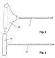
- FIG. 2 and Figure 3 show a per se known biopsy cannula 4 or one for setting the Biopsy cannula 4 existing trocar 19.
- the Grips 21 of the trocar 19 and 22 of the shaft first are each in the handle 20 of the biopsy cannula. 4 lockable firmly positionable.
- the biopsy cannula 4 FIG. 2 shows the trocar 19 of FIG. 3 in FIG set the tissue to be taken.
- Biopsy cannula 4 Based on this placement of the biopsy cannula 4 is in the distal end of the biopsy cannula 4 a cylindrical biopsy 6 in the interior of the Biopsy cannula 4 placed. This placement of Biopsy cannula 4 is shown in FIG. To Placement of the biopsy cannula 4 in the to be taken Fabric and the existing interior Biopsy cylinder 6 is subsequently the shaft 1 via the handle 22 with the existing at the distal end Wire 3 inserted into the biopsy cannula 4 proximally.
- the shaft 1 By setting the shaft 1 to the Locking the handle 22 of the shaft 1 in the Handle 20 of the biopsy cannula 4 will be the placement of the Shaft 1 with the existing at the distal end wire 3 in the figure 5 shown in the drawing.
- the wire. 3 By the given bias angle 2 and the so existing voltage of the wire 3, the wire. 3 by insertion of the shaft 1 in the biopsy cannula 4 directly on the inner wall of the biopsy cannula. 4 between the inner wall and the Biopsatzylinder. 6 driven. Based on the cylindrical design the biopsy cannula 4 at the distal end thereby becomes also a corresponding guide tension of the wire 3 predetermined.
- the length of the shaft 1 with the am distal end given wire 3 is designed so that after insertion and locking of the handle 22 of the shaft 1 in the handle 20 of the biopsy cannula. 4 the tip 5 of the wire 3 immediately at the distal End of the biopsy cannula 4 ends.
- the corresponding biopsy cannula from the to be removed Tissue pulled out, and over an additional given ejector is the corresponding biopsy taken after removal of the shaft 1.
- Based on the very low crushing factor of the biopsy between the inner wall of the biopsy cannula 4 and the Wire 3 of the shaft 1 and the included Biopsy Cylinder 6 is a high quality for further examination of the biopsy specimen.
Landscapes
- Health & Medical Sciences (AREA)
- Life Sciences & Earth Sciences (AREA)
- Medical Informatics (AREA)
- Molecular Biology (AREA)
- Rheumatology (AREA)
- Pathology (AREA)
- Immunology (AREA)
- Engineering & Computer Science (AREA)
- Biomedical Technology (AREA)
- Heart & Thoracic Surgery (AREA)
- Hematology (AREA)
- Orthopedic Medicine & Surgery (AREA)
- Surgery (AREA)
- Animal Behavior & Ethology (AREA)
- General Health & Medical Sciences (AREA)
- Public Health (AREA)
- Veterinary Medicine (AREA)
- Surgical Instruments (AREA)
- Endoscopes (AREA)
- Analysing Materials By The Use Of Radiation (AREA)
- Sampling And Sample Adjustment (AREA)
Description
- Figur 1a:
- Schaft mit Griffstück
- Figur 1b:
- Draht mit Griffstück
- Figur 2:
- Biopsienadel
- Figur 3:
- Trokar
- Figur 4:
- Platzierung Biopsienadel im Biopsat
- Figur 5:
- Platzierung des Schaftes in der Biopsienadel
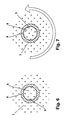
- Figur 6 und 7:
- Ansicht der Biopsienadel und der Nadel 3 mit entsprechender Drehbewegung
- 1
- Schaft
- 2
- Vorspannungswinkel
- 3
- Draht
- 4
- Biopsiekanüle
- 5
- Spitze mit Anschliff
- 6
- Biopsatzylinder
- 7
- Knochenmark
- 8
- Taperung
- 9
- Schneide der Kanüle
- 10
- proximale Verbindungsfläche
- 19
- Trokar
- 20
- Griffstück
- 21
- Griffstück
- 22
- Griffstück Schaft 1
- B
- Anschliffwinkel
Claims (12)
- Biopsathaltevorrichtung für eine Biopsiekanüle (4) zur Ausführung transkutaner Biopsien von Gewebe, insbesondere hartem Gewebe und Knochenmarksgewebe, mit einer in das proximale Ende der Biopsiekanüle (4) einführbaren Biopsathaltevorrichtung, welche zwischen der Innenwand der Biopsiekanüle (4) und dem zu entnehmenden Gewebezylinder einschiebbar ist, dadurch gekennzeichnet, dass ein Draht (3) mit einem Anschliff (5) am distalen Ende des Drahtes (3) an der Biopsathaltevorrichtung angeordnet ist, wobei der Draht (3) einen Vorspannungswinkel (2) aufweist.
- Biopsathaltevorrichtung für eine Biopsiekanüle (4) nach Anspruch 1 dadurch gekennzeichnet, dass sich die Biopsathaltevorrichtung daraus zusammensetzt, dass an einem Griffstück (22) der Draht (3) angeordnet ist.
- Biopsathaltevorrichtung für eine Biopsiekanüle (4) nach Anspruch 1 dadurch gekennzeichnet, dass sich die Biopsathaltevorrichtung daraus zusammensetzt, dass an einem Griffstück (22) ein Schaft (1) zur Verlängerung angeordnet ist und an dem Schaft (1) der Draht (3) vorhanden ist.
- Biopsathaltevorrichtung für eine Biopsiekanüle (4) nach Anspruch 1 dadurch gekennzeichnet, dass der Draht (3) eine Spitze mit einem Anschliff (5) aufweist, wobei die Spitze mit Anschliff (5) einen Anschliffwinkel B von 5 bis 85°, vorteilhafterweise 20°, aufweist und hin zum Biopsatzylinder (6) gerichtet ist.
- Biopsathaltevorrichtung für eine Biopsiekanüle (4) nach den Ansprüchen 1 und 4 dadurch gekennzeichnet, dass der Anschliff (5) des Drahtes (3) einen Hohlschliff oder bauchig ausgestaltet ist.
- Biopsathaltevorrichtung für eine Biopsiekanüle (4) nach Anspruch 1 dadurch gekennzeichnet, dass der Draht (3) mit einem Vorspannungswinkel (2) am Griffstück (22) mittig angeordnet ist, wobei der Vorspannungswinkel (2) zwischen 1 bis 90° vorhanden ist.
- Biopsathaltevorrichtung für eine Biopsiekanüle (4) nach Anspruch 1 dadurch gekennzeichnet, dass der Draht (3) eine Länge aufweist, welche der Biopsiekanüle (4) entspricht und am unmittelbaren Ende endet.
- Biopsathaltevorrichtung für eine Biopsiekanüle (4) nach Anspruch 1 dadurch gekennzeichnet, dass das Griffstück (22) arretierbar in das Griffstück (20) der Biopsiekanüle (4) vorgesehen ist.
- Biopsathaltevorrichtung für eine Biopsiekanüle (4) nach Anspruch 3 dadurch gekennzeichnet, dass der Draht (3) an dem Schaft (1) am distalen Ende fest verbunden ist und ein Vorspannungswinkel (2) zwischen 1 und 90° je nach Anwendungsfall gegeben ist.
- Biopsathaltevorrichtung für eine Biopsiekanüle (4) nach Anspruch 3 dadurch gekennzeichnet, dass die Länge des Drahtes (3) vorteilhafterweise 25 mm aufweist und am unmittelbaren Ende einer an sich bekannten Biopsiekanüle (4) nach Einführung des Schaftes (1) und Arretierung des Griffstückes (22) in den Griff (20) der Biopsiekanüle (4) endet.
- Biopsathaltevorrichtung für eine Biopsiekanüle (4) nach Anspruch 1 dadurch gekennzeichnet, dass der Draht (3) an seiner Oberfläche aufgerauht ist und in einem beliebigen Profil ausgestaltet wird, wobei der Querschnitt des Drahtes (3) so dimensioniert ist, dass eine Fixierung des Drahtes (3) am distalen Ende der Biopsiekanüle (4) eine minimale Quetschartefaktur hervorruft, wobei der Durchmesser vorteilhafterweise ca. 0,35 mm ist.
- Biopsathaltevorrichtung für eine Biopsiekanüle (4) nach Anspruch 3 dadurch gekennzeichnet, dass der Draht (3) seitlich ohne einen Vorspannungswinkel (2) an dem Schaft (1) angeordnet ist und somit an der Innenwand der Biopsiekanüle (4) anliegt.
Priority Applications (7)
| Application Number | Priority Date | Filing Date | Title |
|---|---|---|---|
| SI200330043T SI1413253T1 (sl) | 2002-10-25 | 2003-05-20 | Drzalo biopta za biopsijo z debelo iglo |
| JP2005501533A JP4143642B2 (ja) | 2002-10-25 | 2003-10-23 | バイオプシーカニューレのバイオプサート支持装置 |
| AU2003298096A AU2003298096B2 (en) | 2002-10-25 | 2003-10-23 | Biopsy holder for a biopsy cannula |
| CA002503527A CA2503527A1 (en) | 2002-10-25 | 2003-10-23 | Biopsate holding device for a biopsy cannula |
| US10/532,518 US7662108B2 (en) | 2002-10-25 | 2003-10-23 | Biopsy holder for a biopsy cannula |
| RU2005115962/14A RU2303402C2 (ru) | 2002-10-25 | 2003-10-23 | Устройство для удержания биоптата в биопсийной полой игле-канюле |
| PCT/EP2003/011727 WO2004037093A1 (de) | 2002-10-25 | 2003-10-23 | Biopsathaltevorrichtung für eine biopsiekanüle |
Applications Claiming Priority (2)
| Application Number | Priority Date | Filing Date | Title |
|---|---|---|---|
| DE10250071A DE10250071A1 (de) | 2002-10-25 | 2002-10-25 | Biopsathaltevorrichtung für eine Biopsiekanüle |
| DE10250071 | 2002-10-25 |
Publications (2)
| Publication Number | Publication Date |
|---|---|
| EP1413253A1 EP1413253A1 (de) | 2004-04-28 |
| EP1413253B1 true EP1413253B1 (de) | 2005-04-27 |
Family
ID=32049629
Family Applications (1)
| Application Number | Title | Priority Date | Filing Date |
|---|---|---|---|
| EP03011430A Expired - Lifetime EP1413253B1 (de) | 2002-10-25 | 2003-05-20 | Biopsathaltevorrichtung für eine Biopsiekanüle |
Country Status (6)
| Country | Link |
|---|---|
| EP (1) | EP1413253B1 (de) |
| AT (1) | ATE293918T1 (de) |
| DE (2) | DE10250071A1 (de) |
| ES (1) | ES2242123T3 (de) |
| PL (1) | PL379209A1 (de) |
| PT (1) | PT1413253E (de) |
Family Cites Families (5)
| Publication number | Priority date | Publication date | Assignee | Title |
|---|---|---|---|---|
| US4461305A (en) * | 1981-09-04 | 1984-07-24 | Cibley Leonard J | Automated biopsy device |
| FR2687303B1 (fr) * | 1992-02-19 | 1998-12-04 | Vito Lelio Burgio | Dispositif complementaire des aiguilles ordinaires pour biopsie transcutanee de tissus compacts, notamment de tissu osteo-medullaire. |
| US6080115A (en) * | 1999-02-24 | 2000-06-27 | Rubinstein; Alan I. | Bone marrow biopsy needle |
| US6416484B1 (en) * | 2000-03-24 | 2002-07-09 | Promex, Inc. | Biopsy extractor |
| US6443910B1 (en) * | 2000-04-18 | 2002-09-03 | Allegiance Corporation | Bone marrow biopsy needle |
-
2002
- 2002-10-25 DE DE10250071A patent/DE10250071A1/de not_active Withdrawn
-
2003
- 2003-05-20 AT AT03011430T patent/ATE293918T1/de not_active IP Right Cessation
- 2003-05-20 EP EP03011430A patent/EP1413253B1/de not_active Expired - Lifetime
- 2003-05-20 DE DE50300484T patent/DE50300484D1/de not_active Expired - Lifetime
- 2003-05-20 PT PT03011430T patent/PT1413253E/pt unknown
- 2003-05-20 ES ES03011430T patent/ES2242123T3/es not_active Expired - Lifetime
- 2003-10-23 PL PL379209A patent/PL379209A1/pl not_active IP Right Cessation
Also Published As
| Publication number | Publication date |
|---|---|
| PL379209A1 (pl) | 2006-07-24 |
| EP1413253A1 (de) | 2004-04-28 |
| ATE293918T1 (de) | 2005-05-15 |
| DE10250071A1 (de) | 2004-05-13 |
| PT1413253E (pt) | 2005-09-30 |
| ES2242123T3 (es) | 2005-11-01 |
| DE50300484D1 (de) | 2005-06-02 |
Similar Documents
| Publication | Publication Date | Title |
|---|---|---|
| WO2004037093A1 (de) | Biopsathaltevorrichtung für eine biopsiekanüle | |
| DE4305226C2 (de) | Vorrichtung für Nadeln für transkutane Biopsien | |
| DE69720669T2 (de) | Biopsievorrichtung | |
| DE69526329T2 (de) | Knochenmarkbiopsienadel | |
| DE3918431C1 (de) | ||
| DE102005005007B3 (de) | Biopsienadel zur histologischen Untersuchung von Körpergewebe | |
| WO2009152919A1 (de) | Vorrichtung zur entfernung von knochengewebe bei endoskopischen operationen | |
| DE69106131T2 (de) | Spurführbarer führungsdraht. | |
| DE60318543T2 (de) | Handgriffanordnung für eine Biopsievorrichtung | |
| DE3407084A1 (de) | Vorrichtung zum setzen von chirurgischen klammern | |
| DE29719526U1 (de) | Neurotrokar | |
| DE29511860U1 (de) | Nahtdrahtvorrichtung zur Frakturfixierung | |
| DE3505567A1 (de) | Zapfenfoermiges knochenimplantat und instrument zu dessen implantation | |
| DE2609723A1 (de) | Knochennagel | |
| DE19806693A1 (de) | Tumortherapie | |
| DE3327585A1 (de) | Chirurgisches instrument fuer die epidurale und spinale anaesthesie | |
| EP2575629A1 (de) | Gelenk-biopsienadel zur entnahme von gewebeproben | |
| DE19808220A1 (de) | Nadeltrokar | |
| DE3020926A1 (de) | Kanuele, insbesondere fuer die lumbalpunktion und -injektion | |
| EP0221007A1 (de) | Feinnadel-Biopsiekanüle mit Mandrin | |
| EP0019104A2 (de) | Biopsiekanüle zur Entnahme histologischer Gewebeproben | |
| WO2008017468A2 (de) | Medizinisches hilfsinstrument zum einbringen in den körper eines patienten | |
| DE602004013450T2 (de) | Greifglied für biomezidinische Nadel | |
| DE4320008C2 (de) | Biopsiekanüle | |
| AT509761B1 (de) | Knochenbiopsiefräser |
Legal Events
| Date | Code | Title | Description |
|---|---|---|---|
| PUAI | Public reference made under article 153(3) epc to a published international application that has entered the european phase |
Free format text: ORIGINAL CODE: 0009012 |
|
| AK | Designated contracting states |
Kind code of ref document: A1 Designated state(s): AT BE BG CH CY CZ DE DK EE ES FI FR GB GR HU IE IT LI LU MC NL PT RO SE SI SK TR |
|
| AX | Request for extension of the european patent |
Extension state: AL LT LV MK |
|
| 17P | Request for examination filed |
Effective date: 20040528 |
|
| GRAP | Despatch of communication of intention to grant a patent |
Free format text: ORIGINAL CODE: EPIDOSNIGR1 |
|
| RAP1 | Party data changed (applicant data changed or rights of an application transferred) |
Owner name: SOMATEX MEDICAL TECHNOLOGIES GMBH |
|
| AKX | Designation fees paid |
Designated state(s): AT BE BG CH CY CZ DE DK EE ES FI FR GB GR HU IE IT LI LU MC NL PT RO SE SI SK TR |
|
| GRAS | Grant fee paid |
Free format text: ORIGINAL CODE: EPIDOSNIGR3 |
|
| GRAA | (expected) grant |
Free format text: ORIGINAL CODE: 0009210 |
|
| AK | Designated contracting states |
Kind code of ref document: B1 Designated state(s): AT BE BG CH CY CZ DE DK EE ES FI FR GB GR HU IE IT LI LU MC NL PT RO SE SI SK TR |
|
| PG25 | Lapsed in a contracting state [announced via postgrant information from national office to epo] |
Ref country code: EE Free format text: LAPSE BECAUSE OF FAILURE TO SUBMIT A TRANSLATION OF THE DESCRIPTION OR TO PAY THE FEE WITHIN THE PRESCRIBED TIME-LIMIT Effective date: 20050427 Ref country code: FI Free format text: LAPSE BECAUSE OF FAILURE TO SUBMIT A TRANSLATION OF THE DESCRIPTION OR TO PAY THE FEE WITHIN THE PRESCRIBED TIME-LIMIT Effective date: 20050427 |
|
| REG | Reference to a national code |
Ref country code: GB Ref legal event code: FG4D Free format text: NOT ENGLISH |
|
| REG | Reference to a national code |
Ref country code: CH Ref legal event code: EP |
|
| REG | Reference to a national code |
Ref country code: IE Ref legal event code: FG4D Free format text: LANGUAGE OF EP DOCUMENT: GERMAN |
|
| PG25 | Lapsed in a contracting state [announced via postgrant information from national office to epo] |
Ref country code: CY Free format text: LAPSE BECAUSE OF FAILURE TO SUBMIT A TRANSLATION OF THE DESCRIPTION OR TO PAY THE FEE WITHIN THE PRESCRIBED TIME-LIMIT Effective date: 20050520 Ref country code: LU Free format text: LAPSE BECAUSE OF NON-PAYMENT OF DUE FEES Effective date: 20050520 Ref country code: RO Free format text: LAPSE BECAUSE OF NON-PAYMENT OF DUE FEES Effective date: 20050520 Ref country code: SK Free format text: LAPSE BECAUSE OF NON-PAYMENT OF DUE FEES Effective date: 20050520 |
|
| PG25 | Lapsed in a contracting state [announced via postgrant information from national office to epo] |
Ref country code: MC Free format text: LAPSE BECAUSE OF NON-PAYMENT OF DUE FEES Effective date: 20050531 |
|
| REF | Corresponds to: |
Ref document number: 50300484 Country of ref document: DE Date of ref document: 20050602 Kind code of ref document: P |
|
| PG25 | Lapsed in a contracting state [announced via postgrant information from national office to epo] |
Ref country code: DK Free format text: LAPSE BECAUSE OF FAILURE TO SUBMIT A TRANSLATION OF THE DESCRIPTION OR TO PAY THE FEE WITHIN THE PRESCRIBED TIME-LIMIT Effective date: 20050727 |
|
| PGFP | Annual fee paid to national office [announced via postgrant information from national office to epo] |
Ref country code: BE Payment date: 20050729 Year of fee payment: 3 |
|
| PGFP | Annual fee paid to national office [announced via postgrant information from national office to epo] |
Ref country code: IE Payment date: 20050815 Year of fee payment: 3 |
|
| REG | Reference to a national code |
Ref country code: CH Ref legal event code: NV Representative=s name: RIEDERER HASLER & PARTNER PATENTANWAELTE AG |
|
| PGFP | Annual fee paid to national office [announced via postgrant information from national office to epo] |
Ref country code: FR Payment date: 20050816 Year of fee payment: 3 Ref country code: SI Payment date: 20050816 Year of fee payment: 3 |
|
| REG | Reference to a national code |
Ref country code: SE Ref legal event code: TRGR |
|
| PGFP | Annual fee paid to national office [announced via postgrant information from national office to epo] |
Ref country code: SE Payment date: 20050830 Year of fee payment: 3 |
|
| REG | Reference to a national code |
Ref country code: GR Ref legal event code: EP Ref document number: 20050402274 Country of ref document: GR |
|
| GBT | Gb: translation of ep patent filed (gb section 77(6)(a)/1977) |
Effective date: 20050902 |
|
| REG | Reference to a national code |
Ref country code: PT Ref legal event code: SC4A Effective date: 20050722 |
|
| REG | Reference to a national code |
Ref country code: ES Ref legal event code: FG2A Ref document number: 2242123 Country of ref document: ES Kind code of ref document: T3 |
|
| PGFP | Annual fee paid to national office [announced via postgrant information from national office to epo] |
Ref country code: HU Payment date: 20060201 Year of fee payment: 3 |
|
| PLBE | No opposition filed within time limit |
Free format text: ORIGINAL CODE: 0009261 |
|
| STAA | Information on the status of an ep patent application or granted ep patent |
Free format text: STATUS: NO OPPOSITION FILED WITHIN TIME LIMIT |
|
| REG | Reference to a national code |
Ref country code: RO Ref legal event code: EPE |
|
| ET | Fr: translation filed | ||
| 26N | No opposition filed |
Effective date: 20060130 |
|
| PG25 | Lapsed in a contracting state [announced via postgrant information from national office to epo] |
Ref country code: SI Free format text: LAPSE BECAUSE OF NON-PAYMENT OF DUE FEES Effective date: 20060521 Ref country code: SE Free format text: LAPSE BECAUSE OF NON-PAYMENT OF DUE FEES Effective date: 20060521 Ref country code: HU Free format text: LAPSE BECAUSE OF NON-PAYMENT OF DUE FEES Effective date: 20060521 |
|
| PG25 | Lapsed in a contracting state [announced via postgrant information from national office to epo] |
Ref country code: IE Free format text: LAPSE BECAUSE OF NON-PAYMENT OF DUE FEES Effective date: 20060522 |
|
| PG25 | Lapsed in a contracting state [announced via postgrant information from national office to epo] |
Ref country code: BE Free format text: LAPSE BECAUSE OF NON-PAYMENT OF DUE FEES Effective date: 20060531 |
|
| EUG | Se: european patent has lapsed | ||
| REG | Reference to a national code |
Ref country code: IE Ref legal event code: MM4A |
|
| REG | Reference to a national code |
Ref country code: FR Ref legal event code: ST Effective date: 20070131 |
|
| REG | Reference to a national code |
Ref country code: SI Ref legal event code: KO00 Effective date: 20070122 |
|
| BERE | Be: lapsed |
Owner name: *SOMATEX MEDICAL TECHNOLOGIES G.M.B.H. Effective date: 20060531 |
|
| PG25 | Lapsed in a contracting state [announced via postgrant information from national office to epo] |
Ref country code: FR Free format text: LAPSE BECAUSE OF NON-PAYMENT OF DUE FEES Effective date: 20060531 |
|
| PGFP | Annual fee paid to national office [announced via postgrant information from national office to epo] |
Ref country code: CH Payment date: 20080523 Year of fee payment: 6 Ref country code: CZ Payment date: 20080509 Year of fee payment: 6 Ref country code: ES Payment date: 20080523 Year of fee payment: 6 |
|
| PGFP | Annual fee paid to national office [announced via postgrant information from national office to epo] |
Ref country code: AT Payment date: 20080521 Year of fee payment: 6 |
|
| PGFP | Annual fee paid to national office [announced via postgrant information from national office to epo] |
Ref country code: BG Payment date: 20080530 Year of fee payment: 6 Ref country code: PT Payment date: 20080509 Year of fee payment: 6 |
|
| PGFP | Annual fee paid to national office [announced via postgrant information from national office to epo] |
Ref country code: NL Payment date: 20080523 Year of fee payment: 6 |
|
| PGFP | Annual fee paid to national office [announced via postgrant information from national office to epo] |
Ref country code: GB Payment date: 20080522 Year of fee payment: 6 |
|
| PGFP | Annual fee paid to national office [announced via postgrant information from national office to epo] |
Ref country code: GR Payment date: 20080527 Year of fee payment: 6 |
|
| PG25 | Lapsed in a contracting state [announced via postgrant information from national office to epo] |
Ref country code: TR Free format text: LAPSE BECAUSE OF FAILURE TO SUBMIT A TRANSLATION OF THE DESCRIPTION OR TO PAY THE FEE WITHIN THE PRESCRIBED TIME-LIMIT Effective date: 20050427 |
|
| REG | Reference to a national code |
Ref country code: PT Ref legal event code: MM4A Free format text: LAPSE DUE TO NON-PAYMENT OF FEES Effective date: 20091120 |
|
| REG | Reference to a national code |
Ref country code: CH Ref legal event code: PL |
|
| GBPC | Gb: european patent ceased through non-payment of renewal fee |
Effective date: 20090520 |
|
| PG25 | Lapsed in a contracting state [announced via postgrant information from national office to epo] |
Ref country code: LI Free format text: LAPSE BECAUSE OF NON-PAYMENT OF DUE FEES Effective date: 20090531 Ref country code: CH Free format text: LAPSE BECAUSE OF NON-PAYMENT OF DUE FEES Effective date: 20090531 Ref country code: CZ Free format text: LAPSE BECAUSE OF NON-PAYMENT OF DUE FEES Effective date: 20090520 Ref country code: AT Free format text: LAPSE BECAUSE OF NON-PAYMENT OF DUE FEES Effective date: 20090520 |
|
| NLV4 | Nl: lapsed or anulled due to non-payment of the annual fee |
Effective date: 20091201 |
|
| PG25 | Lapsed in a contracting state [announced via postgrant information from national office to epo] |
Ref country code: NL Free format text: LAPSE BECAUSE OF NON-PAYMENT OF DUE FEES Effective date: 20091201 |
|
| PG25 | Lapsed in a contracting state [announced via postgrant information from national office to epo] |
Ref country code: PT Free format text: LAPSE BECAUSE OF NON-PAYMENT OF DUE FEES Effective date: 20091120 |
|
| PG25 | Lapsed in a contracting state [announced via postgrant information from national office to epo] |
Ref country code: GB Free format text: LAPSE BECAUSE OF NON-PAYMENT OF DUE FEES Effective date: 20090520 |
|
| PG25 | Lapsed in a contracting state [announced via postgrant information from national office to epo] |
Ref country code: GR Free format text: LAPSE BECAUSE OF NON-PAYMENT OF DUE FEES Effective date: 20091202 |
|
| REG | Reference to a national code |
Ref country code: ES Ref legal event code: FD2A Effective date: 20090521 |
|
| PG25 | Lapsed in a contracting state [announced via postgrant information from national office to epo] |
Ref country code: ES Free format text: LAPSE BECAUSE OF NON-PAYMENT OF DUE FEES Effective date: 20090521 |
|
| PG25 | Lapsed in a contracting state [announced via postgrant information from national office to epo] |
Ref country code: BG Free format text: LAPSE BECAUSE OF FAILURE TO SUBMIT A TRANSLATION OF THE DESCRIPTION OR TO PAY THE FEE WITHIN THE PRESCRIBED TIME-LIMIT Effective date: 20090531 |
|
| REG | Reference to a national code |
Ref country code: DE Ref legal event code: R084 Ref document number: 50300484 Country of ref document: DE |
|
| REG | Reference to a national code |
Ref country code: DE Ref legal event code: R082 Ref document number: 50300484 Country of ref document: DE Representative=s name: HOYNG ROKH MONEGIER B.V., NL |
|
| PGFP | Annual fee paid to national office [announced via postgrant information from national office to epo] |
Ref country code: IT Payment date: 20220523 Year of fee payment: 20 Ref country code: DE Payment date: 20220527 Year of fee payment: 20 |
|
| REG | Reference to a national code |
Ref country code: DE Ref legal event code: R071 Ref document number: 50300484 Country of ref document: DE |