EP1412078B1 - Processes for the production of amino-protected derivatives of 4-aminomethylene-pyrrolidin-3-one, gemifloxacin or a salt thereof - Google Patents
Processes for the production of amino-protected derivatives of 4-aminomethylene-pyrrolidin-3-one, gemifloxacin or a salt thereof Download PDFInfo
- Publication number
- EP1412078B1 EP1412078B1 EP02755123A EP02755123A EP1412078B1 EP 1412078 B1 EP1412078 B1 EP 1412078B1 EP 02755123 A EP02755123 A EP 02755123A EP 02755123 A EP02755123 A EP 02755123A EP 1412078 B1 EP1412078 B1 EP 1412078B1
- Authority
- EP
- European Patent Office
- Prior art keywords
- formula
- compound
- mixing
- reactor
- mixing elements
- Prior art date
- Legal status (The legal status is an assumption and is not a legal conclusion. Google has not performed a legal analysis and makes no representation as to the accuracy of the status listed.)
- Expired - Lifetime
Links
- 0 CC=C(C1*C1)C(c1cc(F)c(N(C[C@@]2*=C)CC2=*OC)nc1*C1CC1)=O Chemical compound CC=C(C1*C1)C(c1cc(F)c(N(C[C@@]2*=C)CC2=*OC)nc1*C1CC1)=O 0.000 description 4
Images


Classifications
-
- C—CHEMISTRY; METALLURGY
- C07—ORGANIC CHEMISTRY
- C07D—HETEROCYCLIC COMPOUNDS
- C07D471/00—Heterocyclic compounds containing nitrogen atoms as the only ring hetero atoms in the condensed system, at least one ring being a six-membered ring with one nitrogen atom, not provided for by groups C07D451/00 - C07D463/00
- C07D471/02—Heterocyclic compounds containing nitrogen atoms as the only ring hetero atoms in the condensed system, at least one ring being a six-membered ring with one nitrogen atom, not provided for by groups C07D451/00 - C07D463/00 in which the condensed system contains two hetero rings
- C07D471/04—Ortho-condensed systems
-
- A—HUMAN NECESSITIES
- A61—MEDICAL OR VETERINARY SCIENCE; HYGIENE
- A61P—SPECIFIC THERAPEUTIC ACTIVITY OF CHEMICAL COMPOUNDS OR MEDICINAL PREPARATIONS
- A61P31/00—Antiinfectives, i.e. antibiotics, antiseptics, chemotherapeutics
-
- B—PERFORMING OPERATIONS; TRANSPORTING
- B01—PHYSICAL OR CHEMICAL PROCESSES OR APPARATUS IN GENERAL
- B01F—MIXING, e.g. DISSOLVING, EMULSIFYING OR DISPERSING
- B01F25/00—Flow mixers; Mixers for falling materials, e.g. solid particles
- B01F25/10—Mixing by creating a vortex flow, e.g. by tangential introduction of flow components
-
- B—PERFORMING OPERATIONS; TRANSPORTING
- B01—PHYSICAL OR CHEMICAL PROCESSES OR APPARATUS IN GENERAL
- B01F—MIXING, e.g. DISSOLVING, EMULSIFYING OR DISPERSING
- B01F25/00—Flow mixers; Mixers for falling materials, e.g. solid particles
- B01F25/40—Static mixers
- B01F25/42—Static mixers in which the mixing is affected by moving the components jointly in changing directions, e.g. in tubes provided with baffles or obstructions
- B01F25/43—Mixing tubes, e.g. wherein the material is moved in a radial or partly reversed direction
- B01F25/431—Straight mixing tubes with baffles or obstructions that do not cause substantial pressure drop; Baffles therefor
- B01F25/4314—Straight mixing tubes with baffles or obstructions that do not cause substantial pressure drop; Baffles therefor with helical baffles
- B01F25/43141—Straight mixing tubes with baffles or obstructions that do not cause substantial pressure drop; Baffles therefor with helical baffles composed of consecutive sections of helical formed elements
-
- B—PERFORMING OPERATIONS; TRANSPORTING
- B01—PHYSICAL OR CHEMICAL PROCESSES OR APPARATUS IN GENERAL
- B01J—CHEMICAL OR PHYSICAL PROCESSES, e.g. CATALYSIS OR COLLOID CHEMISTRY; THEIR RELEVANT APPARATUS
- B01J19/00—Chemical, physical or physico-chemical processes in general; Their relevant apparatus
- B01J19/24—Stationary reactors without moving elements inside
- B01J19/2415—Tubular reactors
- B01J19/242—Tubular reactors in series
-
- B—PERFORMING OPERATIONS; TRANSPORTING
- B01—PHYSICAL OR CHEMICAL PROCESSES OR APPARATUS IN GENERAL
- B01J—CHEMICAL OR PHYSICAL PROCESSES, e.g. CATALYSIS OR COLLOID CHEMISTRY; THEIR RELEVANT APPARATUS
- B01J19/00—Chemical, physical or physico-chemical processes in general; Their relevant apparatus
- B01J19/32—Packing elements in the form of grids or built-up elements for forming a unit or module inside the apparatus for mass or heat transfer
-
- C—CHEMISTRY; METALLURGY
- C07—ORGANIC CHEMISTRY
- C07D—HETEROCYCLIC COMPOUNDS
- C07D207/00—Heterocyclic compounds containing five-membered rings not condensed with other rings, with one nitrogen atom as the only ring hetero atom
- C07D207/02—Heterocyclic compounds containing five-membered rings not condensed with other rings, with one nitrogen atom as the only ring hetero atom with only hydrogen or carbon atoms directly attached to the ring nitrogen atom
- C07D207/18—Heterocyclic compounds containing five-membered rings not condensed with other rings, with one nitrogen atom as the only ring hetero atom with only hydrogen or carbon atoms directly attached to the ring nitrogen atom having one double bond between ring members or between a ring member and a non-ring member
- C07D207/22—Heterocyclic compounds containing five-membered rings not condensed with other rings, with one nitrogen atom as the only ring hetero atom with only hydrogen or carbon atoms directly attached to the ring nitrogen atom having one double bond between ring members or between a ring member and a non-ring member with hetero atoms or with carbon atoms having three bonds to hetero atoms with at the most one bond to halogen, e.g. ester or nitrile radicals, directly attached to ring carbon atoms
-
- C—CHEMISTRY; METALLURGY
- C07—ORGANIC CHEMISTRY
- C07D—HETEROCYCLIC COMPOUNDS
- C07D207/00—Heterocyclic compounds containing five-membered rings not condensed with other rings, with one nitrogen atom as the only ring hetero atom
- C07D207/02—Heterocyclic compounds containing five-membered rings not condensed with other rings, with one nitrogen atom as the only ring hetero atom with only hydrogen or carbon atoms directly attached to the ring nitrogen atom
- C07D207/30—Heterocyclic compounds containing five-membered rings not condensed with other rings, with one nitrogen atom as the only ring hetero atom with only hydrogen or carbon atoms directly attached to the ring nitrogen atom having two double bonds between ring members or between ring members and non-ring members
- C07D207/34—Heterocyclic compounds containing five-membered rings not condensed with other rings, with one nitrogen atom as the only ring hetero atom with only hydrogen or carbon atoms directly attached to the ring nitrogen atom having two double bonds between ring members or between ring members and non-ring members with hetero atoms or with carbon atoms having three bonds to hetero atoms with at the most one bond to halogen, e.g. ester or nitrile radicals, directly attached to ring carbon atoms
- C07D207/36—Oxygen or sulfur atoms
-
- B—PERFORMING OPERATIONS; TRANSPORTING
- B01—PHYSICAL OR CHEMICAL PROCESSES OR APPARATUS IN GENERAL
- B01J—CHEMICAL OR PHYSICAL PROCESSES, e.g. CATALYSIS OR COLLOID CHEMISTRY; THEIR RELEVANT APPARATUS
- B01J2219/00—Chemical, physical or physico-chemical processes in general; Their relevant apparatus
- B01J2219/00049—Controlling or regulating processes
- B01J2219/00164—Controlling or regulating processes controlling the flow
- B01J2219/00166—Controlling or regulating processes controlling the flow controlling the residence time inside the reactor vessel
-
- B—PERFORMING OPERATIONS; TRANSPORTING
- B01—PHYSICAL OR CHEMICAL PROCESSES OR APPARATUS IN GENERAL
- B01J—CHEMICAL OR PHYSICAL PROCESSES, e.g. CATALYSIS OR COLLOID CHEMISTRY; THEIR RELEVANT APPARATUS
- B01J2219/00—Chemical, physical or physico-chemical processes in general; Their relevant apparatus
- B01J2219/32—Details relating to packing elements in the form of grids or built-up elements for forming a unit of module inside the apparatus for mass or heat transfer
- B01J2219/322—Basic shape of the elements
- B01J2219/32203—Sheets
- B01J2219/3221—Corrugated sheets
-
- B—PERFORMING OPERATIONS; TRANSPORTING
- B01—PHYSICAL OR CHEMICAL PROCESSES OR APPARATUS IN GENERAL
- B01J—CHEMICAL OR PHYSICAL PROCESSES, e.g. CATALYSIS OR COLLOID CHEMISTRY; THEIR RELEVANT APPARATUS
- B01J2219/00—Chemical, physical or physico-chemical processes in general; Their relevant apparatus
- B01J2219/32—Details relating to packing elements in the form of grids or built-up elements for forming a unit of module inside the apparatus for mass or heat transfer
- B01J2219/322—Basic shape of the elements
- B01J2219/32203—Sheets
- B01J2219/32213—Plurality of essentially parallel sheets
-
- Y—GENERAL TAGGING OF NEW TECHNOLOGICAL DEVELOPMENTS; GENERAL TAGGING OF CROSS-SECTIONAL TECHNOLOGIES SPANNING OVER SEVERAL SECTIONS OF THE IPC; TECHNICAL SUBJECTS COVERED BY FORMER USPC CROSS-REFERENCE ART COLLECTIONS [XRACs] AND DIGESTS
- Y02—TECHNOLOGIES OR APPLICATIONS FOR MITIGATION OR ADAPTATION AGAINST CLIMATE CHANGE
- Y02P—CLIMATE CHANGE MITIGATION TECHNOLOGIES IN THE PRODUCTION OR PROCESSING OF GOODS
- Y02P20/00—Technologies relating to chemical industry
- Y02P20/50—Improvements relating to the production of bulk chemicals
- Y02P20/55—Design of synthesis routes, e.g. reducing the use of auxiliary or protecting groups
Definitions
- the present invention relates to novel processes for the production of compounds which are themselves of use in the production of pharmaceutically active compounds, for example, quinolone carboxylic acid derivatives such as gemifloxacin having antibacterial activity.
- the present invention relates to a process for the production of inter alia amino-protected derivatives of 4-aminomethylene-pyrrolidin-3-one; a process for the production of 4-aminomethyl-3-methoxyimino-pyrrolidine or a salt thereof or oxime-substituent variants thereof; and processes for the production of gemifloxacin or a pharmaceutically acceptable salt and/or hydrate thereof for exmaple including performing one of the aforementioned processes.
- EP 0 688 772 A1 and B1 disclose novel naphthyridine carboxylic acid derivatives having antibacterial activity, including anhydrous (R,S)-7-(3-aminomethyl-4-methoxyimino-pyrrolidin-1-yl)-1-cyclopropyl-6-fluoro-4-oxo-1,4-dihydro-1,8-naphthyridine-3-carboxylic acid.
- WO 98/42705 discloses (R,S)-7-(3-aminomethyl-4- syn -methoxyimino-pyrrolidin-1-yl)-1-cyclopropyl-6-fluoro-4-oxo-1,4-dihydro-1,8-naphthyridine-3-carboxylic acid methanesulfonate (gemifloxacin methanesulfonate or mesylate) and hydrates thereof including the sesquihydrate.
- WO 99/44991 discloses a process for the production of 4-aminomethyl-3-alkoxyiminopyrrolidines and salts thereof from aminomethylpyrrolidin-3-one and the corresponding alkoxylamine.
- a key step in the synthesis of (R,S)-7-(3-aminomethyl-4- syn -methoxyimino-pyrrolidin-1-yl)-1-cyclopropyl-6-fluoro-4-oxo-1,4-dihydro-1,8-naphthyridine-3-carboxylic acid is the protection of the enamino pyrrolidinone with e.g. t-butoxycarbonyl anhydride (Boc 2 O).
- the batch-mode process described in WO 99/44991 involves treating a cooled suspension of 1-(N-t-butoxycarbonyl)-4-aminomethylene-pyrrolidin-3-one (obtained by Raney nickel reduction of the cyanopyrrolidinone) in e.g. isopropanol, THF or toluene, with a solution of t-butoxycarbonyl anhydride in e.g. isopropanol or THF, and with a base such as lithium t-butoxide or aqueous sodium hydroxide solution.
- a cooled suspension of 1-(N-t-butoxycarbonyl)-4-aminomethylene-pyrrolidin-3-one obtained by Raney nickel reduction of the cyanopyrrolidinone
- a solution of t-butoxycarbonyl anhydride in e.g. isopropanol or THF
- a base such as lithium t-butoxide or aqueous sodium hydroxide solution.
- reaction has several potential problems that make the batch-mode operation less than ideal, particularly on a commercial scale.
- the reaction has been found to have extremely fast kinetics and is characterised by being extremely exothermic.
- precise control of several factors e.g. addition time, addition rate, temperature, reaction time, stoichiometry, reagent concentration, etc, is required, as undesired by-products (degradants, dimers and oligomers) can be generated very easily.
- addition time, addition rate, temperature, reaction time, stoichiometry, reagent concentration, etc is required, as undesired by-products (degradants, dimers and oligomers) can be generated very easily.
- the procedure is made more complex as both the product, the starting material and even the t-butoxycarbonyl anhydride are unstable under the basic reaction conditions.
- the present invention relates to a novel process for the production of amino-protected derivatives of 4-aminomethylene-pyrrolidin-3-one which are of use in the synthesis of pharmaceutically active compounds.
- E or Z or a mixture of E and Z .
- the first aspect of the invention also provides: a process for the production of a compound of formula (IA): wherein P 1 and P 2 , which may be the same or different, are amino protecting groups, which comprises protection of a compound of formula (IIA): in solution phase continuous operation mode, wherein the process is conducted in reaction equipment adapted for use in continuous processing mode and being a non back-mixed system, wherein the reaction equipment comprises a plug flow reactor, or one or more static mixers.
- references to a compound of formula (I) or (II) are deemed to refer to / apply to: a compound of formula (I) or (II) respectively; and/or a compound of formula (IA) or (IIA) respectively.
- Continuous operation mode also called “continuous processing mode” can be defined as the bringing together of two or more streams of reagents/starting materials to form a new product, in this case amino-protected derivatives of 4-aminomethylene-pyrrolidin-3-one, the compound of formula (I).
- Protecting groups P 1 and P 2 include any suitable amino protecting groups, the amino protecting groups are preferably removable by acidic conditions e.g. by treatment with methanesulfonic acid.
- protecting groups include formyl, acetyl, trifluoroacetyl, benzoyl, para-toluenesulfonyl, methoxycarbonyl, ethoxycarbonyl, t-butoxycarbonyl, benzyloxycarbonyl, para-methylbenzyloxycarbonyl, trichloroethoxycarbonyl, beta-iodoethoxycarbonyl, benzyl, para-methoxybenzyl, trityl, tetrahydropyranyl and pivaloyl.
- Particular protecting groups that may be mentioned include acetyl, t-butoxycarbonyl and pivaloyl.
- the preferred protecting group for both P 1 and P 2 is t-butoxycarbonyl.
- Protection of the amino group may be performed by reacting the compound of formula (I) with a reagent for introducing the amino-protecting group P 2 , in the presence of a base, e.g. selected from the group consisting of lithium t-butoxide, lithium isopropoxide, potassium t-butoxide, sodium t-butoxide and lithium chloride, sodium hydroxide and potassium hydroxide.
- a base e.g. selected from the group consisting of lithium t-butoxide, lithium isopropoxide, potassium t-butoxide, sodium t-butoxide and lithium chloride, sodium hydroxide and potassium hydroxide.
- the base is preferably potassium hydroxide.
- the base is preferably in aqueous solution.
- the base e.g. sodium or potassium hydroxide e.g. an aqueous solution thereof, is preferably used in excess relative to the compound of formula (II) e.g.
- “Kenics® KM-type” static mixers as described below, and/or where residence times are about 5 to about 60 seconds, preferably 10 to 30 seconds; then preferably the base is used at a stoichiometry of ⁇ 5 or ⁇ 6 equivalents, preferably 5 to 15, 5 to 12 or 6 to 12 equivalents, more preferably 5 to 7 or 6 to 7 equivalents, most preferably about 6 equivalents, relative to the compound of formula (II).
- Such a large number of equivalents is desirable to improve conversion where short residence times are used, e.g. as is typicaly the case with a "Kenics® KM-type” mixer and similar static mixers, cf. the batch mode reaction usually takes at least 30 minutes.
- the reagent for introducing the amino-protecting group may be selected from the group consisting of, for example, t-butoxycarbonyl anhydride, pivaloyl chloride and acetyl chloride.
- a stream of aqueous base e.g. potassium hydroxide
- a stream of a solution of 1-(N-protected)-4-aminomethylene-pyrrolidin-3-one of formula (II) containing the reagent for introducing the amino-protecting group e.g. t-butoxycarbonyl anhydride
- acid e.g. hydrochloric acid or preferably aqueous acetic acid.
- the acid quench is a mixture of acetic acid, water and isopropanol, more preferably about 2:1:1 by volume.
- a first stream of aqueous base e.g. potassium hydroxide
- a (separate) third stream containing (e.g. in solution) the reagent for introducing the amino-protecting group e.g. t-butoxycarbonyl anhydride
- acid e.g. hydrochloric acid or preferably aqueous acetic acid.
- one or both of the 1-(N-protected)-4-aminomethylene-pyrrolidin-3-one of formula (II) and the reagent for introducing the amino-protecting group, e.g. t-butoxycarbonyl anhydride, are not stored in the presence of base prior to the continuous operation mode protection process of the invention.
- the choice of solvent for the reaction will depend on the particular reagents used.
- a base such as potassium hydroxide
- the solution of 1-(N-protected)-4-aminomethylene-pyrrolidin-3-one of formula (I), optionally containing the reagent for introducing the amino-protecting group is preferably an isopropanol/water solution.
- An alternative solvent is THF/water.
- a solution of 1-(N-protected)-4-aminomethylene-pyrrolidin-3-one of formula (I) and/or of the reagent for introducing the amino-protecting group is an isopropanol/water solution
- it is a solution in about 20:1 to about 1:1 v/v isopropanol : water or about 10:1 to about 1:1 v/v isopropanol : water, more preferably about 10:1 to about 2:1 v/v isopropanol : water or about 8:1 to about 3:1 v/v isopropanol : water, most preferably about 5:1 v/v isopropanol : water.
- the Boc anhydride is readily soluble and stays soluble on cooling. When the isopropanol concentration is raised too far, then this may decrease the solubility of any hydroxide base during the reaction.
- the process (protection process) of the first aspect of the invention is preferably carried out using THF/water or more preferably isopropanol/water as solvent.
- the protection process is carried out using as solvent: about 10:1 to about 1:2 v/v isopropanol : water or about 5:1 to about 1:2 v/v isopropanol : water, more preferably about 3:1 to about 2:3 v/v isopropanol : water or about 2:1 to about 1:1 v/v isopropanol : water, most preferably about 5:3 to about 5:4 v/v isopropanol : water.
- the process of the invention is preferably conducted at a temperature of less than 20°C, preferably at a temperature of about -30 to less than 20 °C, more preferably about -25 to about 10 °C or about -20 to about 10 °C, still more preferably about -25 to about 0 °C or about -20 to about 0 °C, even more preferably about -15 °C to about 0 °C.
- the process for the production of a compound of formula (I), according to the invention is conducted in any reaction equipment adapted for use in continuous processing mode (continuous operation mode).
- Continuous processing being operated usually in steady state mode, usually offers the advantages of small reaction inventory and improved control of operating conditions.
- Enhanced mass transfer (mixing) and heat transfer ensure that substantially no concentration or temperature gradients exist.
- the reaction equipment adapted for use in continuous processing (continuous operating) mode preferably comprises a substantially tubular reactor to form the product of formula (I) and in which or upstream of which two, three or more streams of the reagents/starting materials are brought together.
- the substantially tubular reactor is preferably straight but may be otherwise e. g. in the form of a coil.
- the tubular reactor (housing) is preferably made of metal, e.g. steel or a metal alloy containing 1,2,3 or more of Fe, Ni, Cr, Mo; preferably a Fe-Ni-Cr-Mo alloy such as SS316. SS316 alloy material is well-known to the skilled person.
- the substantially tubular reactor e.g.
- the jacket temperature thereof is preferably at a temperature of less than 20°C, preferably about ⁇ about -40, ⁇ about -30, ⁇ about -23, ⁇ about -20, or ⁇ about -15 °C, preferably ⁇ about 0 °C, ⁇ about -5, or ⁇ about -15 °C; for example about -23 to about 0 °C, about -23 to about -5 °C, about -23 to about -15 °C (e.g. about -20 °C) or about -15 °C to about -5 °C or about -15 to about 0 °C.
- the ideal reactor temperature may depend on the apparatus and conditions used (e.g. see the Examples).
- the tubular reactor may be provided with a jacket adapted to receive circulating fluid (e.g. liquid such as silicone oil) during use operating to control the temperature of, e.g. cool, the tubular reactor.
- circulating fluid e.g. liquid such as silicone oil
- the reactor may be cooled by immersion e.g. submerging in a coolant bath, for example containing ice/water or ice/salt water (about 0 °C or less) or ethylene glycol (e.g. about -15 °C).
- the reaction equipment comprises a plug flow reactor, or one or more static mixers.
- mixing is induced either passively through the fluid flow (e.g. static mixer, plug flow reactor) or actively through mixing devices (e.g. CSTR's in cascade, oscillatory flow reactor).
- CSTR's in cascade, oscillatory flow reactor e.g. CSTR's in cascade, oscillatory flow reactor.
- Equipment such as plug flow reactors or static mixers are non back-mixed systems, which provide substantially no axial diffusion and substantial (good) radial homogeneity.
- Oscillatory flow reactors are partly back-mixed systems.
- the mixing time in the equipment is preferably shorter than the reaction half life, which is the time required to reach 50% conversion, so that the reaction is in a kinetically controlled regime. Residence time can then be adjusted to reach the required conversion.
- a typical IPFR comprises a substantially tubular reactor, preferably a jacketed tubular reactor, fitted with internal mixing elements, e.g. Sulzer® SMV mixing elements; as described above, mixing is induced passively through the fluid flow.
- the mixing elements inside the pipe continually split and remix the reaction streams promoting mass and heat transfer.
- the jacket of the jacketed tubular reactor is preferably adapted to receive circulating fluid (e.g. liquid such as silicone oil) during use operating to control the temperature of, e.g. cool, the tubular reactor.
- IPFR Intensified Plug Flow Reactor
- the internal mixing elements may project inwardly from the inner circumferential surface of the tubular reactor and/or the internal mixing elements may be integrally formed with the inner circumferential surface of the tubular reactor, but preferably one or more (preferably most or all) of the internal mixing elements comprise an one or more inserts insertable into the inside of the tubular reactor and capable of being positioned in substantially fixed (static) relation to the reactor.
- Sulzer static mixing elements / static mixers / plug flow reactors are obtainable from Sulzer Chemtech (UK) Ltd, Westmead, Farnborough, Hampshire GU14 7LP, UK, tel: +44 1252 544311; Sulzer Chemtech Ltd, Separation and Reaction Technology, P.O. Box 65, CH-8404 Winterthur, Switzerland, tel: +41 52 262 67 20; www.sulzerchemtech.com.
- the following mixing elements / mixers are suitable: the Sulzer® SMV mixer; the Sulzer® SMR mixer-reactor; or possibly the Sulzer® SMXL mixer-heat exchanger, e.g. as shown in http://www.sulzerchemtech.
- Sulzer® SMV mixers may require a longer reaction time than the Kenics ® KM-type static mixer described below" but are highly suitable and effective for large quantities and turbulent/plug flow conditions.
- one or more (e.g. most or all) of the static mixers or the plug flow reactor comprises one or more static mixing elements, wherein some, most or all of the mixing elements comprise a plurality of (e.g. about 3, 4, 5 or 6) stacked corrugated sheets, wherein the grooves of each corrugated sheet are transverse to, more preferably substantially perpendicular to, the grooves of any directly adjacent corrugated sheet (e.g. the sheet directly above and the sheet directly below).
- “Stacked” in this context means “flat-stacked", i.e. the grooves of the corrugated sheets are directed generally towards (i.e.
- the plurality of stacked corrugated sheets splits and mixes the fluid stream width-wise across the sheets; so that in more general terms one or more (e.g. most or all) of the static mixers or the plug flow reactor comprises one or more static mixing elements, wherein some, most or all of the mixing elements are adapted to split and mix a fluid stream flowing therethrough substantially in one dimension transverse to the fluid flow.
- the mixing elements are substantially cylindrical in outside profile so as to fit snugly within the tubular reactor, with the cylinder axis being substantially parallel to the planes of the corrugated sheets.
- a plurality of the mixing elements are substantially axially aligned within the substantially tubular reactor, with the corrugated sheets arranged so as to allow fluid flow longitudinally along the tubular reactor.
- Adjacent mixing elements are preferably in contact with each other, and are usually not attached or fused to each other, but some, most or all of the mixing elements optionally can be attached or fused into a unitary composite mixing structure.
- Mixing elements are preferably kept in approximately static relation to the tubular reactor by mixing-element fixing means.
- the fixing means can be an open end cap (e.g.
- each mixing element in the tubular reactor is statically arranged so as to be in a rotated orientation (preferably rotated substantially perpendicularly e.g. by 70-110° e.g. by about 90°) about the longitudinal axis of the tubular reactor relative to one or both of the neighbouring mixing elements.
- each mixing element is turned by 90° about the longitudinal axis relative to the mixing element on either side of it; one example of such an arrangement of the mixing elements in the tubular reactor is shown in Figure 10 .
- the first element splits and mixes the stream from side to side
- the second element splits and mixes the stream in an up-down direction
- the third element splits and mixes the stream side to side
- Sulzer® SMV mixing elements and static mixers are of this type (“Sulzer SMV-type").
- the aqueous KOH stream and the isopropanol/water stream containing both Boc 2 O (Boc anhydride) and the compound of formula (II) where P 1 is t-butyloxycarbonyl are usually initially miscible, but salt formation during the reaction causes a change in the density of the aqueous stream which can cause the IPA-containing stream and aqueous stream to split (i.e. become immiscible) during the reaction in the absence of efficient and rapid mixing elements in the tubular reactor.
- An alternative but similar approach to the IPFR is to incorporate one or more static mixers to obtain the required mixing, e.g. as shown schematically in Figure 3 .
- Two streams can be brought together and then passed through a static mixer or a series of static mixers, e.g. Kenics® static mixers (e.g. length 20cm, od 0.5 cm, id 0.33 cm), in particular Kenics® KM static mixers.
- the outlet from the one or more static mixers preferably passes into an acid quench.
- the number of mixers used is dependant up on the dimensions of the mixer, the flow rate and efficiency of mixing.
- Kenics® static mixers are obtainable from: Chemineer, a unit of R&M Ltd., Cranmer Road, West Meadows, Derby DE21 6XT, United Kingdom; or Chemineer, Inc., 125 Flagship Drive, North Andover, Massachusetts 01845, USA (see also http://www.chemineer.com/main.php for general information and ..../km.php for Kenics® KM static mixers).
- one or more (e.g. all) of the static mixers comprise one or more mixing elements arranged (or capable of being arranged) substantially axially within and in substantially static relation to a substantially tubular reactor, and the mixing elements define at least one substantially helical fluid flow path in the axial direction between the mixing element and the inner circumferential walls of the tubular reactor.
- mixing elements are herein named "Kenics® KM-type" static mixers.
- two or more substantially helical fluid flow paths are so defined.
- the mixing elements are helically-twisted about their axis so as to define the at least one substantially helical fluid flow path.
- the static mixers comprise one or more helically-twisted mixing elements arranged axially within and in substantially static relation to substantially tubular reactor; usually they comprise a series of alternating right- and left-handed helically-twisted mixing elements, i.e. having alternating rotational directions.
- each or most mixing element(s) is/are a plate, preferably with about 180° of helical twist.
- a leading edge of each element is located substantially perpendicularly (e.g. at about 90°) to a trailing edge of the following element.
- As the fluids pass through each element they are usually divided by the power of two since each successive element is offset by about 90°.
- Figures 11 and 12 One example of this arrangement is shown in Figures 11 and 12 .
- the series of alternating right- and left-handed helical structure improves radial mixing by giving the fluid element radial and angular momentum.
- the helical twist angle, offset angle, width and height of the mixing element may vary depending on the property of feed.
- These "Kenics® KM-type" static mixers improves the speed of mixing and gives a higher surface to volume ratio than a tank reactor which is usually used in batch-mode reaction.
- Adjacent "Kenics® KM-type" mixing elements are preferably in contact with each other when in the reactor.
- some, most or all of the mixing elements may be attached or fused to each other to form a unitary composite mixing structure; e.g. there is one unitary composite mixing structure per tubular reactor and/or the composite mixing structure is optionally insertable into the inside of the reactor (e.g. see Kenics static mixing technology catalogue for fused mixing structure examples).
- the tubular reactor has an internal diameter of about 0.1 to about 10.0 cm and/or ⁇ 0.33 cm, preferably 0.33 to about 3.0 cm, more preferably 0.33 to about 1.3 cm internal diameter.
- a too large diameter may give difficulties removing the heat of reaction sufficiently, and a too small diameter gives productivity and throughput difficulties.
- the tubular reactor (housing) and/or the mixing elements are made of metal, e.g. steel or a metal alloy containing 1,2,3 or more of Fe, Ni, Cr, Mo; preferably a Fe-Ni-Cr-Mo alloy such as SS316.
- some, most or all of the "Kenics® KM-type” static mixers contain 4-100 or 6-50 or 10-40 or most preferably about 27 "Kenics® KM-type” mixing elements. It is the total number of Kenics elements that is important, and/or the total length of the reaction path in the plurality of mixers; the number of static mixer units can be varied according to the number of elements each static mixer unit has.
- reaction equipment adapted for use in the continuous processing mode process preferably comprises 20-400, 40-300, 70-200, 90-180 or about 135 "Kenics® KM-type" mixing elements arranged in series within one or more substantially tubular reactors.
- the total number of elements also can vary with the mixing performance per element, which depends on the size of the element and the flow rate used.
- static mixer / mixing elements which might possibly be usable in the continuous processing mode of the invention include: dispersive/distributive static mixer, KAM static mixer, wafer type static mixer, Komax static mixer, Kenics HEV type static mixer; and mixers / mixing elements published in: EP 0 472 491 B1 , EP 0 478 497 B1 , EP 0 546 989 B1 , EP 0 655 275 B1 , EP 0 749 776 B1 , EP 0 727 249 B1 , EP 0 760 253 B1 , EP 0 800 857 A1 , EP 0 815 929 B1 (all Sulzer Chemtech AG).
- the two, three or more streams of the reagents/starting materials may be brought together in a or the reactor (e.g. the substantially tubular reactor) (see for example Example 6), or may optionally be brought together upstream of the reactor by various stream-mixing means.
- the optional stream-mixing means may be a three-way, four-way or other junction.
- the stream-mixing means may optionally be a direct junction which contains substantially no mixing chamber (i.e. has a low dead-volume) at the junction.
- This preferably is a three-way direct junction i.e. a "T-piece" which includes T- and Y-shaped and other shaped pieces. See for example Figure 3A and Example 3.
- the stream-mixing means may comprise a substantial mixing chamber having two, three or more reagent inlets in fluid communication with the stored reagents and an outlet in fluid communication with the reactor (e.g. the substantially tubular reactor).
- the stream-mixing means comprises a substantial mixing chamber
- the stream-mixing means is a vortex mixer adapted to mix at least partly the reagent streams in use by generation of a vortex in the mixing chamber and/or in the outlet (this might only achieve a partial mixing).
- the vortex mixer has a substantially cylindrical mixing chamber (e.g. a substantially disc-shaped, i.e. substantially flat-cylindrical, mixing chamber) and the outlet is substantially axially disposed.
- the reagent inlets are arranged at or adjacent the circumference of the cylindrical chamber and for example are directed substantially tangentially at or adjacent the circumference. See for example Example 9 and Figures 13 and 14 . Details of suitable vortex mixers are disclosed in Example 9 hereinafter, and the following references incorporated herein by reference: WO 95/21173 A1 (Figs 1A and 1B), WO 00/53282 (see Fig. 1 and page 2 line 18 to page 3 line 5 and especially the mixing chamber dimensions given therein); see also WO 01/32125 A2 ( Fig 6 and pages 12-13) and EP 0 646 407 A1 .
- the stream-mixing means is preferably made of metal, e.g. steel such as stainless steel or a metal alloy containing 1,2,3 or more of Fe, Ni, Cr, Mo; preferably a Fe-Ni-Cr-Mo alloy such as SS316.
- metal e.g. steel such as stainless steel or a metal alloy containing 1,2,3 or more of Fe, Ni, Cr, Mo; preferably a Fe-Ni-Cr-Mo alloy such as SS316.
- the stream-mixing means e.g. the direct junction or vortex mixer, is preferably at a temperature of less than 20°C; preferably about ⁇ about -40, ⁇ about - 30, ⁇ about -23, ⁇ about -20, or ⁇ about -15 °C; preferably ⁇ about 0 °C, ⁇ about -5, or ⁇ about -15 °C.
- the stream-mixing means may be cooled by immersion e.g. submerging in a coolant bath, for example containing ice/water or ice/salt water (about 0 °C or less) or ethylene glycol (e.g. about -15 °C).
- the residence time can be about 1 second to about 30 minutes or about 5 seconds to about 20 minutes.
- the residence time can be about 5 to about 2 minutes or about 5 to about 60 seconds, preferably 10 to 30 seconds, especially when static mixers are used comprising one or more helically-twisted mixing elements arranged axially within and in static relation to a tube (tubular reactor), e.g. "Kenics KM-type" static mixers, e.g. as shown in Table 4 in Example 2 (residence times 10, 20 and 30 seconds) and Examples 2-4.
- the residence time can be about 1 minute to about 20 minutes, e.g. about 3 to about 20 minutes, e.g. about 4.8 minutes or about 13 minutes e.g. as shown in Table 2 in Example 1.
- the compounds of formula (II) may be prepared by the processes described in US 5,633,262 , EP 688772A1 and WO 99/44991 ( PCT/KR99/00099 ).
- the compounds of formula (I) are useful as an intermediates for preparing quinolone antibacterials particularly those described in US 5,633,262 and EP 688772A1 (e.g. see Example 180 of EP 688772A1 for gemifloxacin with an undefined oxime sterochemistry).
- Gemifloxacin the compound of formula (III) below, is indicated for the treatment of respiratory tract infections such as community acquired pneumonia, acute exacerbations of chronic bronchitis and acute sinusitis; uncomplicated urinary tract infections; and for the treatment of bacterial infections as disclosed in EP 688772A1 , WO 01/00209 A1 , WO 01/15695 A1 , and WO 01/21176 A1 .
- the compound of formula (I) may be converted to a compound of formula (IV) by selective reduction of the double bond carried out using a metal catalyst, e.g. a transition metal catalyst, such as Raney-nickel, palladium-carbon or Lindlar's catalyst, followed by reaction with a compound of formula (VI): Me-ONH 2 (VI) or a salt thereof (e.g. the HCl salt, Me-ONH 2 .HCl) followed by deprotection of the amino groups, and, optionally, salt formation.
- a metal catalyst e.g. a transition metal catalyst, such as Raney-nickel, palladium-carbon or Lindlar's catalyst
- a compound of formula (VI): Me-ONH 2 (VI) or a salt thereof e.g. the HCl salt, Me-ONH 2 .HCl
- WO 99/44991 PCT/KR99/00099 , e.g. Examples 7 and 8 and Reference Example 1
- the reaction of the compounds of formulae (IV) and (V) is preferably conducted in the presence of a base e.g. triethylamine. Further details regarding the reaction of the compounds of formula (IV) and (V) can be found in US 5,633,262 and EP 688772A1 .
- the compounds of formula (V) may be synthesisied as described in US 5,633,262 and EP 688772A1 .
- the compound of formula (III) produced according to this aspect of the invention is preferably (R,S)-7-(3-aminomethyl-4-syn-methoxyimino-pyrrolidin-1-yl)-1-cyclopropyl-6-fluoro-4-oxo-1,4-dihydro-1,8-naphthyridine-3-carboxylic acid methanesulfonate or a hydrate thereof, preferably the sesquihydrate, as disclosed in WO 98/42705 .
- the methanesulfonate and hydrates thereof may be synthesised from the free acid as described in WO 98/42705 and WO 00/17199 .
- a further aspect of the invention provides a compound of formula (III), or a pharmaceutically acceptable salt and/or hydrate thereof, (a) obtainable by, or (b) which has been (whenever) obtained (produced) by, a process according to the second aspect of the invention.
- Example 1 Process example using Intensified Plug Flow Reactor
- IPFR Intensified Plug Flow Reactor
- IPA isopropanol
- Table 1 compares the HPLC results obtained for impurity profiles in the batch-mode reaction and in the IPFR static mixer for the by-products created: Table 1 - impurity profiles Compound IPFR Static mixer Batch mode [% HPLC area] [% HPLC area] Isomer 6.2 3.1 Dimers 0.09 0.8 The isomer (of the compound of formula (I)) is consumed in the next hydrogenation stage. The dimers created in the batch-mode reaction reduce the crystallisation yield and are due to inadequate temperature control in the batch-mode reaction.
- Example 1 the outlet temperature was also measured for each of the above three test results and was found to be -1.3, -11.1 and -3.2 °C respectively (i.e. for the above tests using jacket temperatures of -20, -23 and -15 °C respectively).
- the empty pipe Reynolds numbers for these 3 optional experiments were 60, 23, 23 respectively.
- the main advantage of operating this process in continuous mode is the reduction of dimer impurity levels in the reacted mixture by one order of magnitude compared to the batch-mode reaction. These impurities are known to rise with extended exposure to the alkaline reaction mixture and increased reaction temperature. On occasion they have even reached levels in prepared batches where crystallisation of the product has been hindered. These adverse conditions can be avoided or mitigated in continuous mode, which features superior control over degree of mixing, uniformity of bulk temperature and reaction mixture residence time.
- Figure 2 compares quantities of by-products obtained for the two operating modes: batch and continuous.
- Example 2 Process examples using a series of Kenics® static mixers
- Example 2 In an alternative embodiment of Example 2, the above Example 2 processes were repeated using the apparatus shown in Figure 3A and described in Example 3 below.
- Example 2 In another alternative embodiment of Example 2, some scale up work on this process has been undertaken and by using larger static mixers flow rates of 2L/min have been achieved with similar conversion rates (this is exemplified in Example 4).
- Example 3 Process example using Kenics® KM static mixers, and apparatus therefor
- the laboratory apparatus 50 used in the above Example 3 process is shown as a schematic diagram in Figure 3A .
- the material of contruction of the static mixers 51 (both the tubular housing and the mixing elements) is SS316, a well-known Fe-Ni-Cr-Mo alloy.
- the five static mixers 51 are arranged in series in fluid communication with each other and all mixers are submerged in a first temperature-controlled coolant bath 52.
- Two sealed feed tanks 53A, 53B submerged in a second temperature-controlled coolant bath 54 contain the two reagent solutions, namely:
- the reagent solutions can be pumped out of the tanks 53A, 53B via pumps 55A, 55B into pipes 56A, 56B which enter the first coolant bath 52 and then become joined in a simple T-piece 57 made of SS316 Fe-Ni-Cr-Mo alloy. After mixing of the reagent streams the mixture enters the first of the five mixers 51. The distance between the T-piece 57 and the first mixer 51 is as short as possible. Downstream of the five mixers 51, an reacted mixture pipe 58 is fed into an open-topped receiving vessel 59 containing the acid to quench the reaction.
- Example 3 the first and second coolant baths 52 and 54 are both ice baths maintained at 0 °C.
- suitable cooling media such as ethylene glycol can be used e.g. to achieve lower temperatures. Temperatures of -15 °C can be achieved using ethylene glycol coolant.
- Example 4 Large-scale process example using a Kenics® static mixer
- the Kenics KM static mixer having outside diameter of 1.3 cm and internal diameter of 1.09 cm was used with a flow rate of 1 L/min and the residence time was 15 sec. A solution of 10 equivalents of 50 % w/w potassium hydroxide in water was used. When both feed streams were cooled down to 0 °C and the coolant temperature around the Kenics KM static mixer was set to 0 °C, the conversion > 96 % was achieved.
- the reaction mixture was passed through a mixing chamber and into the tubular reactor (two 7.5m x 10mm pipes T 1 and T 2 ) situated in a cool bath maintained at -5 to -15°C.
- the outflow was quenched into acetic acid (or in an alternative embodiment, quenched into a mixture of acetic acid, water and isopropanol 2:1:1 by volume).
- the protected enaminoketone, 1-(N-t-butoxycarbonyl)-4-(N-t-butoxycarbonyl)aminomethylene-pyrrolidin-3-one was isolated by heating the quenched mixture to 35 to 40°C thus creating two layers. The bottom aqueous layer was separated off and discarded.
- the two reactor pipes T 1 and T 2 are coiled stainless steel tubes, the coolant baths for the two tubes contain glycol, the first tube T 1 is in a bath cooled to -15 °C to remove the heat of the reaction, and the second tube T 2 is in a bath cooled to -5 °C to maintain the desired reaction temperature.
- Example 5 In another optional variation of Example 5, the empty pipe Reynolds number was 1350, and the following other reaction parameters were used: Residence time (mins) Formula (II) solution flow rate (mL/min) aqueous KOH flow rate (mL/min) Jacket temperature (°C) % Conversion 4.9 150 90 -15 and -5 93.5
- Example 5 Another variation of Example 5 involves the replacement of the two reactor pipes T 1 and T 2 with a single coiled stainless steel reactor tube submerged in a glycol coolant bath, and replacement of the mixing chamber with a 3-way stainless steel T-piece low dead-volume connector.
- the T-piece mixes the two reagent fluid streams and the resultant mixed stream passes to the cooled reactor tube.
- IPFR Intensified Plug Flow Reactor
- FIG. 5 shows a schematic diagram of an Intensified Plug Flow Reactor (IPFR) apparatus, in more detail than the IPFR shown in Figure 1 .
- IPFR Intensified Plug Flow Reactor
- the Figure 5 apparatus can optionally be used as the IPFR plug flow reactor in the continuous processing mode reaction of the first aspect of the invention described in Example 1.
- the apparatus 1 for use in the continuous processing mode reaction comprises first and second jacketed feed tanks 3, 5 containing two separate reagent solutions, the feed tanks 3, 5 being in fluid communication with a tubular plug flow reactor 11 (IPFR) respectively via inlet ports 7, 9 which are at or adjacent one end of the reactor 11.
- IPFR tubular plug flow reactor 11
- the reactor 11 is adapted to continually mix and split the two input reagent streams as they pass therealong.
- An outlet port 13 at or adjacent the opposing (downstream) end of the reactor 11 allows the reaction stream(s) to flow out from the reactor and into an open-topped receiver tank 15.
- the jackets of the reagent feed tanks 3, 5 are hollow and are in fluid communication with a circular heat exchanger circuit 17 adapted to contain a heat transfer fluid in which circuit the tanks 3, 5 and a Lauda heat exchanger 19 are connected in series. This allows the feed tanks to be cooled or heated as desired.
- the two pre-heated or pre-cooled streams containing reagents for the reaction can be fed from the two jacketed feed tanks 3, 5 via two separately controlled gear pumps 21, 23 and feed lines 25, 27 into the tubular reactor 11.
- These Micropumps 21, 23 are controlled by inverters, allowing a combined total flow range of from 30 to 400 mL.min -1 .
- Both pump outlets are fitted with pressure gauges and non-return valves 29, 33 to ensure that over-pressurisation and back flow do not occur in the feed lines.
- tubular reactor 11 two versions were built: one made of glass for initial observation and demonstration purposes and one made of SS316 alloy (a well-known Fe-Ni-Cr-Mo alloy) to carry out reactions.
- SS316 alloy a well-known Fe-Ni-Cr-Mo alloy
- the tubular reactor 11 is fitted vertically as shown in Figure 5 , and has an internal diameter of 25.4 mm and a length of 750 mm, creating a total liquid hold-up volume of 350 mL.
- the reactor 11 can be fitted with precision diameter Halar ETFE Sulzer® SMV mixing elements, for example as described in Example 7.
- Halar ETFE is chosen as material of construction for the mixing elements as it offers good resistance to most chemicals commonly encountered in pharmaceuticals processes.
- the "Sulzer® SMV-type" geometry of the mixing elements is selected on considerations regarding versatility. These mixing elements can handle low viscosity solvents but also gas/liquid systems and immiscible liquids of medium viscosity without generating excessive pressure drop which might affect the pumps 21, 23.
- the reactor 11 is provided with a jacket 37 over the whole length of the reactor 11, the jacket 37 being in fluid communication via line 39 with a Huber CC231® heat exchanger 41.
- the reactor 11 is heated or cooled by a heat transfer fluid (silicone oil) flowing through the jacket body 37.
- a heat transfer fluid silicone oil
- Using the silicone oil with the Huber CC231® heat transfer unit allows a wide temperature range for the experiments, from -30 to 250°C.
- the receiver tank 15 is also jacketed to allow quenching of the reacted stream 43, if necessary.
- All equipment is suitably earthed and fitted within a metal framework in a walk-in fume cupboard 45.
- Sampling points are installed at the pumps outlets and at the reactor inlets 7, 9 and outlet 13.
- thermocouples are fitted in the reactor: at or near the mixing point of the two inlet streams 7, 9, at mid-length of the reactor (not shown) and at or near the outlet of the reactor 13. These thermocouples are connected to a digital thermometer 47 via lines some of which are shown as dot-dash lines in Figure 5 .
- a pressure relief valve is fitted on the reactor 11 and two additional pressure relief valves 31, 35 are fitted immediately after the pumps 21, 23 and linked to a recirculation loop (not shown) to the feed tanks 3, 5.
- the first feed tank 3 has a 5 litre capacity and contains the 30% w/w aqueous potassium hydroxide solution; and the second feed tank 5 has a 10 litre capacity and contains the 1-(N-t-butoxycarbonyl)-4-aminomethylene-pyrrolidin-3-one of formula (II) and the Boc 2 O (e.g. 1.2 equivalents) in isopropanol/water (e.g. 5:1 v/v) under a nitrogen blanket.
- Both tanks 3, 5 are cooled down to -5°C.
- Both streams 25, 27 are fed into the jacketed static mixer 11 cooled down to -20°C.
- the reacted mixture obtained is then quenched into the 15-litre stirred collection tank 15 containing acetic acid, demineralised water and isopropanol (IPA) (e.g. 2:1:1 acetic acid : water : IPA by volume).
- IPA isopropanol
- Example 7 "Sulzer® SMV-type" static mixing element and a plug flow reactor containing such mixing elements
- Figures 6-9 show a "Sulzer® SMV-type" static mixing element which can be used in a plug flow reactor in the continuous mode process of the invention, especially with the apparatus/process of Examples 1 and 6.
- Figures 6-9 illustrate a static mixing element 60 comprising a plurality of (here, five) stacked corrugated sheets 62, 64, 66, 68, 70, wherein the grooves 72, 72A, 74, 74A, 76, 78, 80 of each corrugated sheet are substantially perpendicular to the grooves of each directly adjacent corrugated sheet (i.e. the sheet directly above and the sheet directly below).
- "Stacked” in this context means “flat-stacked", i.e. with reference to the exploded top perspective view of Figure 8 the grooves (e.g. 74, 74A) of the corrugated sheets (e.g. 64) are directed generally towards (i.e. generally face) the grooves (e.g.
- any directly adjacent corrugated sheet e.g. 64, 66 respectively.
- the mixing element 60 in use the plurality of stacked corrugated sheets splits and mixes the fluid stream width-wise across the sheets.
- the mixing element is substantially cylindrical in outside profile 82, so as to fit snugly within an tubular reactor/housing 84, with the cylinder axis being substantially parallel to the planes of the corrugated sheets 62-70.
- Halar ETFE is chosen as material of construction for the mixing elements 60 as it offers good resistance to most chemicals commonly encountered in pharmaceuticals processes.
- the mixing elements 60 when inside a pipe continually split and remix the reaction streams 85-94 promoting mass and heat transfer.
- a pipe e.g. a plug flow reactor
- a plurality of the mixing elements 60 are substantially axially aligned within an elongated tubular reactor (tubular housing) 102, with the corrugated sheets 62-68 arranged so as to allow fluid flow longitudinally along the tubular reactor 100.
- Adjacent mixing elements 60 are in contact with each other, and in this case are not attached or fused to each other.
- the mixing elements 60A-F are kept in approximately static relation to the tubular reactor 100 by mixing-element fixing means 104, 106.
- the fixing means 104, 106 shown comprise a open end cap (S-shaped as illustrated) fixable or fixed across both ends of the tubular reactor 100; these are capable of allowing fluid flow therethrough and are capable of holding and/or compressing the mixing elements 60A-F together within the tubular reactor.
- Each of the mixing elements e.g. 60C in the tubular reactor 100 are statically arranged so as to be in a rotated orientation (here, by about 90°) about the longitudinal axis of the tubular reactor 100 relative to the mixing element e.g. 60B, 60D on either side of it.
- the first element 60A splits and mixes the stream from side to side
- the second element 60B splits and mixes the stream in an up-down direction
- the third element 60C splits and mixes the stream side to side, etc. etc.
- This arrangement ensures good efficient and rapid mixing and splitting of streams in both directions transverse to the axial direction and is suitable for turbulent/plug flow in the tubular reactor/housing 100 and/or immiscible liquid streams.
- the "Sulzer® SMV-type" geometry of the mixing elements 60 is selected on considerations regarding versatility. These mixing elements 60 can handle low viscosity solvents but also gas/liquid systems and immiscible liquids of medium viscosity without generating excessive pressure drop.
- Example 8 "Kenics KM-type" static mixer and mixing elements
- Figures 11 and 12 are top perspective views of three "Kenics KM-type" static mixing elements axially disposed in a (cut-away) tubular reactor/housing, as described in the general description hereinabove.
- a mixing structure 120 comprises three Kenics® KM static mixing elements 122, 124, 126, of the type obtainable from Chemineer, UK or US (address hereinabove), either fused together or separate but in contact with each other.
- the mixing elements 122, 124, 126 are plates, formed from SS316-type Fe-Ni-Cr-Mo metal alloy, which are helically-twisted about their longitudinal axis. The elements are aligned in series in the axial direction (Figues 12) and in use have been inserted axially within and in substantially static relation to a tubular reactor 150 (e.g. length 20cm, outside diameter 0.5 cm, inside diameter 0.33 cm).
- the mixing elements 122, 124, 126 in series have a alternating right- and left-handed helically-twisted orientation as shown, i.e. they having alternating rotational directions 140, 142.
- Each mixing element is a plate with about 180° of helical twist as shown in the Figures 11 and 12 .
- a leading edge 130, 134 of each element 122, 124 is located at about 90° to a trailing edge 132, 136 of the following element 124, 126.
- the helical twist angle, offset angle, width and height of the mixing element may vary depending on the property of the feed.
- the helical twist of the mixing elements creates a helical fluid flow path 144 between the inner circumferential walls 150 of the tubular reactor and the plates 122-126, the flow path being split in 2 at each element intersection 130-132, 134-136 and the next helical path is in the opposite angular direction (cf, 140, 142).
- Figure 11 shows the movement and rotation 140, 142 of the fluid flowing along the tubular reactor/housing.
- the figures show that the mixing elements 122-126 improve the degree of fluid mixing by imposing some radial and angular momentum on the fluid.
- the total number of mixing elements 122-124 in the tubular reactor 150 can vary with the mixing performance per element, which depends on the size of the element and the flow rate used, but in this case there are 27 elements in series in the tube 150.
- Example 9 vortex mixer as stream-mixing means
- FIGS 13 and 14 illustrate, in cross-sectional views, a vortex mixer which can optionally be used in the processes of Examples 2-5 and/or as part of the apparatus of Figure 5 (Example 6), in order to give a preliminary mixing of the two reagent streams, firstly the formula (II) compound and Boc 2 O stream and secondly the aqueous KOH stream, before the combined stream enters the static mixer(s) or plug flow reactor. It is particularly suitable for use as the "mixing chamber" of Figure 4 and used in Example 5.
- a vortex mixer 160 comprises a metal casing 166, 172 in the form of a hollow disc 166 having an open-ended axially disposed outlet 172.
- the hollow space in the disc is a disc-shaped (flat-cylindrical) mixing chamber 168.
- Two reagent inlets 162, 164 leading outside the casing 166 are connected to the circumference of the mixing chamber 168 and are directed tangentially to the circumference.
- the reagent inlets 162, 164 are in liquid communication with the reagents stored in tanks or other vessels (not shown) and the outlet 170, 172 is connected via a short length of pipe (not shown) with the upstream end of a tubular reactor (not shown).
- the vortex mixer casing 166, 172 is made of metal; for example stainless steel or a metal alloy containing 1,2,3 or more of Fe, Ni, Cr, Mo, e.g. a Fe-Ni-Cr-Mo alloy such as SS316.
- the vortex mixer 160 is preferably cooled to about-30 to about 0 °C by submerging in a coolant bath for example containing ice/water or ethylene glycol (e.g. about -15 °C).
- the reagent streams are pumped into the mixing chamber 168 via inlets 162, 164 and are at least partially mixed therein by generation of a vortex in the mixing chamber 168 and/or in the outlet space 170.
- the mixed reagents exit out of the outlet 170, 172 and into the tubular reactor.
- Triethylamine (5.1ml) was added to 7-chloro-1-cyclopropyl-6-fluoro-4-oxo-1,4-dihydm-1,8-naphthyridine-3-carboxylic acid (3.05g) in water (25ml) at 15-20°C and the mixture stirred for 20 min.
- 4-Aminomethyl-3-methoxyimino-pyrrolidinium dimethanesulfonate (“ AM19 ", 3.86g) was added, followed by water (5ml), and the mixture stirred at 20-25°C for 17% hours.
- Example 11 Example 4 of WO 01/17961 A2 .
- Example 13 gemifloxacin methanesulfonate sesquihydrate - large scale version of Example 12
- This large-scale process was performed substantially as in Example 13 having scaled up the reagents and solvents (e.g. using about 100 kg, or more or less, of (R,S)-7-(3-aminomethyl-4- syn -methoxyiminopyrrolidin-1-yl)-1-cyclopropyl-6-fluoro-4-oxo-1,4-dihydro-1,8-naphthyridine-3-carboxylic acid methanesulfonate).
- the dried product was exposed to a passing stream of humid (wet) nitrogen, for example having about 70% to about 95 % relative humidity, at ambient temperature (e.g. 20-25 °C), either overnight (e.g. about 18 hours) or for some other necessary period, to give the methanesulfonate sesquihydrate.
- the wet nitrogen was obtained by bubbling dry nitrogen through a water bubbler.
- the product was sucked dry for 30 min and then further dried at 50-55°C under vacuum.
- the dried product was exposed to the atmosphere for about 18 hours, preferably under humid conditions, or alternatively under humid nitrogen as in Example 14, to give the methanesulfonate sesquihydrate 21.29 g (85%), purity >99.5% by HPLC.
- the X-ray diffraction pattern of the gemifloxacin methanesulfonate sesquihydrate was measured as follows: Diffractometer type: PW1710 BASED Monochromator used: YES Tube anode: Cu Start angle [°2 ⁇ ]: 3.500 Generator tension [kV]: 40 End angle [°2 ⁇ ]: 35.000 Generator current [mA]: 30 Step size [°2 ⁇ ]: 0.020 Wavelength Alpha1 [A]: 1.54060 Maximum intensity: 2970.250 Wavelength Alpha2 [ ⁇ ]: 1.54439 Time per step [s]: 2.300 Intensity ratio (alpha1/alpha2): 0.500 Type of scan: STEP Divergence slit: AUTOMATIC Minimum peak tip width: 0.10 Irradiated length [mm]: 12 Maximum peak tip width: 1.00 Receiving slit: 0.1 Peak base width: 2.00 Spinner: ON Minimum significance: 0.50
- the X-ray diffraction pattern of gemifloxacin methanesulfonate sesquihydrate is shown in Figure 15 .
Landscapes
- Chemical & Material Sciences (AREA)
- Organic Chemistry (AREA)
- Chemical Kinetics & Catalysis (AREA)
- Health & Medical Sciences (AREA)
- Dispersion Chemistry (AREA)
- Thermal Sciences (AREA)
- Physics & Mathematics (AREA)
- General Health & Medical Sciences (AREA)
- Oncology (AREA)
- Pharmacology & Pharmacy (AREA)
- Life Sciences & Earth Sciences (AREA)
- Animal Behavior & Ethology (AREA)
- Medicinal Chemistry (AREA)
- Public Health (AREA)
- Veterinary Medicine (AREA)
- General Chemical & Material Sciences (AREA)
- Nuclear Medicine, Radiotherapy & Molecular Imaging (AREA)
- Communicable Diseases (AREA)
- Organic Low-Molecular-Weight Compounds And Preparation Thereof (AREA)
- Pyrrole Compounds (AREA)
- Pharmaceuticals Containing Other Organic And Inorganic Compounds (AREA)
- Nitrogen Condensed Heterocyclic Rings (AREA)
- Saccharide Compounds (AREA)
- Low-Molecular Organic Synthesis Reactions Using Catalysts (AREA)
Abstract
Description
- The present invention relates to novel processes for the production of compounds which are themselves of use in the production of pharmaceutically active compounds, for example, quinolone carboxylic acid derivatives such as gemifloxacin having antibacterial activity. In particular, the present invention relates to a process for the production of inter alia amino-protected derivatives of 4-aminomethylene-pyrrolidin-3-one; a process for the production of 4-aminomethyl-3-methoxyimino-pyrrolidine or a salt thereof or oxime-substituent variants thereof; and processes for the production of gemifloxacin or a pharmaceutically acceptable salt and/or hydrate thereof for exmaple including performing one of the aforementioned processes.
-
EP 0 688 772 A1
-
WO 98/42705 -
WO 99/44991 PCT/KR99/00099 - A key step in the synthesis of (R,S)-7-(3-aminomethyl-4-syn-methoxyimino-pyrrolidin-1-yl)-1-cyclopropyl-6-fluoro-4-oxo-1,4-dihydro-1,8-naphthyridine-3-carboxylic acid is the protection of the enamino pyrrolidinone with e.g. t-butoxycarbonyl anhydride (Boc2O). The batch-mode process described in
WO 99/44991 PCT/KR99/00099 
- However, this reaction has several potential problems that make the batch-mode operation less than ideal, particularly on a commercial scale. The reaction has been found to have extremely fast kinetics and is characterised by being extremely exothermic. To ensure a high yield of quality material on scale up of this process precise control of several factors e.g. addition time, addition rate, temperature, reaction time, stoichiometry, reagent concentration, etc, is required, as undesired by-products (degradants, dimers and oligomers) can be generated very easily. Furthermore, the procedure is made more complex as both the product, the starting material and even the t-butoxycarbonyl anhydride are unstable under the basic reaction conditions. For example the enamine ketone and the product will undergo base hydrolysis to give the corresponding enol and this can lead to the formation of uncharacterised oligomers. Dimer/by-product formation prevents crystallisation of the product thereby reducing the isolated yield. Hence, there is a need to develop alternative methods for the production of amino-protected derivatives of 4-aminomethylene-pyrrolidin-3-one which are suitable for use on a commercial scale.
- The present invention relates to a novel process for the production of amino-protected derivatives of 4-aminomethylene-pyrrolidin-3-one which are of use in the synthesis of pharmaceutically active compounds.
- According to a first aspect of the invention there is provided a process for the production of a compound of formula (I):


- The C=C double bond in formula (I) and/or (II) can be in any configuration; e.g. E or Z or a mixture of E and Z. When this process is used in the synthesis of gemifloxacin or a salt thereof, these E/Z ratio are not usually important as this C=C double bond is usually reduced in the next step of the synthesis.
- The first aspect of the invention also provides: a process for the production of a compound of formula (IA):


- "Continuous operation mode", also called "continuous processing mode", can be defined as the bringing together of two or more streams of reagents/starting materials to form a new product, in this case amino-protected derivatives of 4-aminomethylene-pyrrolidin-3-one, the compound of formula (I).
- Protecting groups P1 and P2 include any suitable amino protecting groups, the amino protecting groups are preferably removable by acidic conditions e.g. by treatment with methanesulfonic acid. Examples of protecting groups include formyl, acetyl, trifluoroacetyl, benzoyl, para-toluenesulfonyl, methoxycarbonyl, ethoxycarbonyl, t-butoxycarbonyl, benzyloxycarbonyl, para-methylbenzyloxycarbonyl, trichloroethoxycarbonyl, beta-iodoethoxycarbonyl, benzyl, para-methoxybenzyl, trityl, tetrahydropyranyl and pivaloyl. Particular protecting groups that may be mentioned include acetyl, t-butoxycarbonyl and pivaloyl. The preferred protecting group for both P1 and P2 is t-butoxycarbonyl.
- Protection of the amino group may be performed by reacting the compound of formula (I) with a reagent for introducing the amino-protecting group P2, in the presence of a base, e.g. selected from the group consisting of lithium t-butoxide, lithium isopropoxide, potassium t-butoxide, sodium t-butoxide and lithium chloride, sodium hydroxide and potassium hydroxide. The base is preferably potassium hydroxide. The base is preferably in aqueous solution. The base, e.g. sodium or potassium hydroxide e.g. an aqueous solution thereof, is preferably used in excess relative to the compound of formula (II) e.g. at a stoichiometry of 2.5 to 4 equivalents, or ≥4 or ≥5 equivalents, relative to the compound of formula (II). However, in an alternative embodiment; and especially but not exclusively where static mixers are used comprising one or more helically-twisted mixing elements arranged axially within and in static relation to a tube (tubular reactor), e.g. "Kenics® KM-type" static mixers as described below, and/or where residence times are about 5 to about 60 seconds, preferably 10 to 30 seconds; then preferably the base is used at a stoichiometry of ≥5 or ≥6 equivalents, preferably 5 to 15, 5 to 12 or 6 to 12 equivalents, more preferably 5 to 7 or 6 to 7 equivalents, most preferably about 6 equivalents, relative to the compound of formula (II). Such a large number of equivalents is desirable to improve conversion where short residence times are used, e.g. as is typicaly the case with a "Kenics® KM-type" mixer and similar static mixers, cf. the batch mode reaction usually takes at least 30 minutes.
- The reagent for introducing the amino-protecting group may be selected from the group consisting of, for example, t-butoxycarbonyl anhydride, pivaloyl chloride and acetyl chloride.
- When P2 is t-butoxycarbonyl the protection of the compound of formula (II) is preferably achieved by reaction with t-butoxycarbonyl anhydride in the presence of potassium hydroxide e.g. aqueous potassium hydroxide solution.
- In the continuous operation mode of the invention, preferably a stream of aqueous base, e.g. potassium hydroxide, and a stream of a solution of 1-(N-protected)-4-aminomethylene-pyrrolidin-3-one of formula (II) containing the reagent for introducing the amino-protecting group, e.g. t-butoxycarbonyl anhydride, are brought together prior to quenching in acid, e.g. hydrochloric acid or preferably aqueous acetic acid. This is a two-stream system. Preferably, the acid quench is a mixture of acetic acid, water and isopropanol, more preferably about 2:1:1 by volume.
- In an alternative embodiment of the continuous operation mode of the invention, a first stream of aqueous base, e.g. potassium hydroxide, a second stream of a solution of 1-(N-protected)-4-aminomethylene-pyrrolidin-3-one of formula (II), and a (separate) third stream containing (e.g. in solution) the reagent for introducing the amino-protecting group, e.g. t-butoxycarbonyl anhydride, are brought together prior to quenching in acid, e.g. hydrochloric acid or preferably aqueous acetic acid.
- In all systems, it is strongly preferable that one or both of the 1-(N-protected)-4-aminomethylene-pyrrolidin-3-one of formula (II) and the reagent for introducing the amino-protecting group, e.g. t-butoxycarbonyl anhydride, are not stored in the presence of base prior to the continuous operation mode protection process of the invention.
- The choice of solvent for the reaction will depend on the particular reagents used. When a base such as potassium hydroxide is used, the solution of 1-(N-protected)-4-aminomethylene-pyrrolidin-3-one of formula (I), optionally containing the reagent for introducing the amino-protecting group, is preferably an isopropanol/water solution. An alternative solvent is THF/water. These solvent sytems are also suitable where a (separate) third stream comprising a solution of the reagent for introducing the amino-protecting group is used. When a solution of 1-(N-protected)-4-aminomethylene-pyrrolidin-3-one of formula (I) and/or of the reagent for introducing the amino-protecting group, is an isopropanol/water solution, then preferably it is a solution in about 20:1 to about 1:1 v/v isopropanol : water or about 10:1 to about 1:1 v/v isopropanol : water, more preferably about 10:1 to about 2:1 v/v isopropanol : water or about 8:1 to about 3:1 v/v isopropanol : water, most preferably about 5:1 v/v isopropanol : water. With this most preferred solvent mixture, the Boc anhydride is readily soluble and stays soluble on cooling. When the isopropanol concentration is raised too far, then this may decrease the solubility of any hydroxide base during the reaction.
- The process (protection process) of the first aspect of the invention is preferably carried out using THF/water or more preferably isopropanol/water as solvent. Preferably, the protection process is carried out using as solvent: about 10:1 to about 1:2 v/v isopropanol : water or about 5:1 to about 1:2 v/v isopropanol : water, more preferably about 3:1 to about 2:3 v/v isopropanol : water or about 2:1 to about 1:1 v/v isopropanol : water, most preferably about 5:3 to about 5:4 v/v isopropanol : water. In general, these reaction solvent systems maximise the solubility during the reaction of: the compound of formula (II) especially where P1 = P2 = Boc, the reagent for introducing P2, and the base.
- The process of the invention is preferably conducted at a temperature of less than 20°C, preferably at a temperature of about -30 to less than 20 °C, more preferably about -25 to about 10 °C or about -20 to about 10 °C, still more preferably about -25 to about 0 °C or about -20 to about 0 °C, even more preferably about -15 °C to about 0 °C.
- The process for the production of a compound of formula (I), according to the invention, is conducted in any reaction equipment adapted for use in continuous processing mode (continuous operation mode). Continuous processing, being operated usually in steady state mode, usually offers the advantages of small reaction inventory and improved control of operating conditions. Enhanced mass transfer (mixing) and heat transfer ensure that substantially no concentration or temperature gradients exist.
- The reaction equipment adapted for use in continuous processing (continuous operating) mode preferably comprises a substantially tubular reactor to form the product of formula (I) and in which or upstream of which two, three or more streams of the reagents/starting materials are brought together. The substantially tubular reactor is preferably straight but may be otherwise e. g. in the form of a coil. The tubular reactor (housing) is preferably made of metal, e.g. steel or a metal alloy containing 1,2,3 or more of Fe, Ni, Cr, Mo; preferably a Fe-Ni-Cr-Mo alloy such as SS316. SS316 alloy material is well-known to the skilled person. During the continuous operation mode process, the substantially tubular reactor (e.g. the jacket temperature thereof) is preferably at a temperature of less than 20°C, preferably about ≥ about -40, ≥ about -30, ≥ about -23, ≥ about -20, or ≥ about -15 °C, preferably ≤ about 0 °C, ≤ about -5, or ≤ about -15 °C; for example about -23 to about 0 °C, about -23 to about -5 °C, about -23 to about -15 °C (e.g. about -20 °C) or about -15 °C to about -5 °C or about -15 to about 0 °C. The ideal reactor temperature may depend on the apparatus and conditions used (e.g. see the Examples). The tubular reactor may be provided with a jacket adapted to receive circulating fluid (e.g. liquid such as silicone oil) during use operating to control the temperature of, e.g. cool, the tubular reactor. Alternately, in use, the reactor may be cooled by immersion e.g. submerging in a coolant bath, for example containing ice/water or ice/salt water (about 0 °C or less) or ethylene glycol (e.g. about -15 °C).
- The reaction equipment comprises a plug flow reactor, or one or more static mixers. In this equipment, mixing is induced either passively through the fluid flow (e.g. static mixer, plug flow reactor) or actively through mixing devices (e.g. CSTR's in cascade, oscillatory flow reactor). For example, see those described in Stonestreet P. Van der Veeken PMJ, "The effects of oscillatory flow and bulk flow components on residence time distribution in baffled tube reactors", Chemical Engineering Research & Design. 77(A8):671-684, 1999 Nov; Streiff, F. A.; Rogers, J. A.; "Don't overlook static mixer reactors", Chem. Eng.(N.Y) 101, 6 (1994), 76-82; and Levenspiel, O.; Chemical Reaction Engineering, Wiley, New York, 1993.
- Equipment such as plug flow reactors or static mixers are non back-mixed systems, which provide substantially no axial diffusion and substantial (good) radial homogeneity. Oscillatory flow reactors are partly back-mixed systems. The mixing time in the equipment is preferably shorter than the reaction half life, which is the time required to reach 50% conversion, so that the reaction is in a kinetically controlled regime. Residence time can then be adjusted to reach the required conversion.
- One approach uses a plug flow reactor being an Intensified Plug Flow Reactor Rig (IPFR), e.g. as shown schematically in
Figure 1 . Efficient mixing is necessary for a successful reaction, the IPFR offers benefits with respect to reaction rate and selectivity. A typical IPFR comprises a substantially tubular reactor, preferably a jacketed tubular reactor, fitted with internal mixing elements, e.g. Sulzer® SMV mixing elements; as described above, mixing is induced passively through the fluid flow. The mixing elements inside the pipe continually split and remix the reaction streams promoting mass and heat transfer. Thus, even for low flow-rates and Reynolds numbers, a uniform plug flow profile with turbulent fluid flow can be achieved. The jacket of the jacketed tubular reactor is preferably adapted to receive circulating fluid (e.g. liquid such as silicone oil) during use operating to control the temperature of, e.g. cool, the tubular reactor. - The use of the Intensified Plug Flow Reactor or IPFR has been described in C. Brechtelsbauer and F. Ricard, Organic Process Research & Development, 2001 (November), 5,646-651, published on 27 October 2001 on the internet. The contents of this reference, especially but non-exclusively the theory and experimental results regarding residence time, Bodenstein number, heat transfer, kinetics, etc, are incorporated herein by reference.
- Whether for plug flow or static mixers, the internal mixing elements may project inwardly from the inner circumferential surface of the tubular reactor and/or the internal mixing elements may be integrally formed with the inner circumferential surface of the tubular reactor, but preferably one or more (preferably most or all) of the internal mixing elements comprise an one or more inserts insertable into the inside of the tubular reactor and capable of being positioned in substantially fixed (static) relation to the reactor.
- Sulzer static mixing elements / static mixers / plug flow reactors are obtainable from Sulzer Chemtech (UK) Ltd, Westmead, Farnborough, Hampshire GU14 7LP, UK, tel: +44 1252 544311; Sulzer Chemtech Ltd, Separation and Reaction Technology, P.O. Box 65, CH-8404 Winterthur, Switzerland, tel: +41 52 262 67 20; www.sulzerchemtech.com. For example, the following mixing elements / mixers are suitable: the Sulzer® SMV mixer; the Sulzer® SMR mixer-reactor; or possibly the Sulzer® SMXL mixer-heat exchanger, e.g. as shown in http://www.sulzerchemtech. com/eprise/SulzerChemtech/Sites/products_services/staticMixers/mixers.html and Sulzer Chemtech's Mixing and Reaction technology catalogues. Sulzer® SMV mixers may require a longer reaction time than the Kenics ® KM-type static mixer described below" but are highly suitable and effective for large quantities and turbulent/plug flow conditions.
- Preferably, one or more (e.g. most or all) of the static mixers or the plug flow reactor comprises one or more static mixing elements, wherein some, most or all of the mixing elements comprise a plurality of (e.g. about 3, 4, 5 or 6) stacked corrugated sheets, wherein the grooves of each corrugated sheet are transverse to, more preferably substantially perpendicular to, the grooves of any directly adjacent corrugated sheet (e.g. the sheet directly above and the sheet directly below). "Stacked" in this context means "flat-stacked", i.e. the grooves of the corrugated sheets are directed generally towards (i.e. generally face) the grooves of any directly adjacent corrugated sheet; one example of this arrangement is shown in
Figures 6 to 9 (Sulzer® SMV mixing element - "Sulzer SMV-type"). In the generalised mixing element, the plurality of stacked corrugated sheets splits and mixes the fluid stream width-wise across the sheets; so that in more general terms one or more (e.g. most or all) of the static mixers or the plug flow reactor comprises one or more static mixing elements, wherein some, most or all of the mixing elements are adapted to split and mix a fluid stream flowing therethrough substantially in one dimension transverse to the fluid flow. - Preferably, the mixing elements are substantially cylindrical in outside profile so as to fit snugly within the tubular reactor, with the cylinder axis being substantially parallel to the planes of the corrugated sheets.
- Preferably, a plurality of the mixing elements (e.g. 3, 4, 5 or more) are substantially axially aligned within the substantially tubular reactor, with the corrugated sheets arranged so as to allow fluid flow longitudinally along the tubular reactor. Adjacent mixing elements are preferably in contact with each other, and are usually not attached or fused to each other, but some, most or all of the mixing elements optionally can be attached or fused into a unitary composite mixing structure. Mixing elements are preferably kept in approximately static relation to the tubular reactor by mixing-element fixing means. The fixing means can be an open end cap (e.g. S-shaped) fixable or fixed across one or both ends of the tubular reactor capable of allowing fluid flow therethrough and capable of holding and/or compressing the mixing elements together within the tubular reactor. Preferably, some or all of the mixing elements in the tubular reactor are statically arranged so as to be in a rotated orientation (preferably rotated substantially perpendicularly e.g. by 70-110° e.g. by about 90°) about the longitudinal axis of the tubular reactor relative to one or both of the neighbouring mixing elements. Preferably, each mixing element is turned by 90° about the longitudinal axis relative to the mixing element on either side of it; one example of such an arrangement of the mixing elements in the tubular reactor is shown in
Figure 10 . Here, the first element splits and mixes the stream from side to side, the second element splits and mixes the stream in an up-down direction, the third element splits and mixes the stream side to side, etc. Sulzer® SMV mixing elements and static mixers are of this type ("Sulzer SMV-type"). - This arrangement ensures good efficient and rapid mixing and splitting of streams in both directions and is suitable for turbulent/plug flow and/or immiscible liquid streams. For example, for the protection process of the invention according to Examples 1-5, the aqueous KOH stream and the isopropanol/water stream containing both Boc2O (Boc anhydride) and the compound of formula (II) where P1 is t-butyloxycarbonyl are usually initially miscible, but salt formation during the reaction causes a change in the density of the aqueous stream which can cause the IPA-containing stream and aqueous stream to split (i.e. become immiscible) during the reaction in the absence of efficient and rapid mixing elements in the tubular reactor.
- An alternative but similar approach to the IPFR is to incorporate one or more static mixers to obtain the required mixing, e.g. as shown schematically in
Figure 3 . Two streams can be brought together and then passed through a static mixer or a series of static mixers, e.g. Kenics® static mixers (e.g. length 20cm, od 0.5 cm, id 0.33 cm), in particular Kenics® KM static mixers. The outlet from the one or more static mixers preferably passes into an acid quench. The number of mixers used is dependant up on the dimensions of the mixer, the flow rate and efficiency of mixing. - Kenics® static mixers are obtainable from: Chemineer, a unit of R&M Ltd., Cranmer Road, West Meadows, Derby DE21 6XT, United Kingdom; or Chemineer, Inc., 125 Flagship Drive, North Andover, Massachusetts 01845, USA (see also http://www.chemineer.com/main.php for general information and ..../km.php for Kenics® KM static mixers).
- In the static mixer embodiment, preferably, one or more (e.g. all) of the static mixers comprise one or more mixing elements arranged (or capable of being arranged) substantially axially within and in substantially static relation to a substantially tubular reactor, and the mixing elements define at least one substantially helical fluid flow path in the axial direction between the mixing element and the inner circumferential walls of the tubular reactor. These are herein named "Kenics® KM-type" static mixers. Preferably, two or more substantially helical fluid flow paths are so defined. Preferably, the mixing elements are helically-twisted about their axis so as to define the at least one substantially helical fluid flow path. Usually, one or more (e.g. all) of the static mixers comprise one or more helically-twisted mixing elements arranged axially within and in substantially static relation to substantially tubular reactor; usually they comprise a series of alternating right- and left-handed helically-twisted mixing elements, i.e. having alternating rotational directions.
- Preferably, each or most mixing element(s) is/are a plate, preferably with about 180° of helical twist. Preferably, a leading edge of each element is located substantially perpendicularly (e.g. at about 90°) to a trailing edge of the following element. As the fluids pass through each element, they are usually divided by the power of two since each successive element is offset by about 90°. One example of this arrangement is shown in
Figures 11 and 12 . The series of alternating right- and left-handed helical structure improves radial mixing by giving the fluid element radial and angular momentum. The helical twist angle, offset angle, width and height of the mixing element may vary depending on the property of feed. These "Kenics® KM-type" static mixers improves the speed of mixing and gives a higher surface to volume ratio than a tank reactor which is usually used in batch-mode reaction. - Adjacent "Kenics® KM-type" mixing elements are preferably in contact with each other when in the reactor. Optionally, some, most or all of the mixing elements may be attached or fused to each other to form a unitary composite mixing structure; e.g. there is one unitary composite mixing structure per tubular reactor and/or the composite mixing structure is optionally insertable into the inside of the reactor (e.g. see Kenics static mixing technology catalogue for fused mixing structure examples).
- Preferably, for these "Kenics® KM-type" static mixers, the tubular reactor has an internal diameter of about 0.1 to about 10.0 cm and/or ≥0.33 cm, preferably 0.33 to about 3.0 cm, more preferably 0.33 to about 1.3 cm internal diameter. A too large diameter may give difficulties removing the heat of reaction sufficiently, and a too small diameter gives productivity and throughput difficulties. Preferably, the tubular reactor (housing) and/or the mixing elements are made of metal, e.g. steel or a metal alloy containing 1,2,3 or more of Fe, Ni, Cr, Mo; preferably a Fe-Ni-Cr-Mo alloy such as SS316.
- These "Kenics® KM-type" static mixers are available from Chemineer at the above contact addresses, and are described (a) on Chemineer's internet site given above and (b) in Chemineer, Inc.'s "Kenics static mixing technology" brochure, 1998 available by post or via the internet site. They have also been described in "Applied Process Design for Chemical and Petrochemical Plants" by Ernest E. Ludwig, 2nd Edition, , see e.g. on and around page 203.
- In a preferable embodiment, a plurality of (e.g. 2-10, e.g. 3- 8, most preferably about five) static mixers, e.g. "Kenics® KM-type" static mixers, are connected in series. Preferably, some, most or all of the "Kenics® KM-type" static mixers contain 4-100 or 6-50 or 10-40 or most preferably about 27 "Kenics® KM-type" mixing elements. It is the total number of Kenics elements that is important, and/or the total length of the reaction path in the plurality of mixers; the number of static mixer units can be varied according to the number of elements each static mixer unit has. Therefore the reaction equipment adapted for use in the continuous processing mode process preferably comprises 20-400, 40-300, 70-200, 90-180 or about 135 "Kenics® KM-type" mixing elements arranged in series within one or more substantially tubular reactors. The total number of elements also can vary with the mixing performance per element, which depends on the size of the element and the flow rate used.
- Other types of static mixer / mixing elements which might possibly be usable in the continuous processing mode of the invention include: dispersive/distributive static mixer, KAM static mixer, wafer type static mixer, Komax static mixer, Kenics HEV type static mixer; and mixers / mixing elements published in:
EP 0 472 491 B1EP 0 478 497 B1EP 0 546 989 B1EP 0 655 275 B1EP 0 749 776 B1EP 0 727 249 B1EP 0 760 253 B1EP 0 800 857 A1EP 0 815 929 B1 - The two, three or more streams of the reagents/starting materials may be brought together in a or the reactor (e.g. the substantially tubular reactor) (see for example Example 6), or may optionally be brought together upstream of the reactor by various stream-mixing means. The optional stream-mixing means may be a three-way, four-way or other junction.
- The stream-mixing means may optionally be a direct junction which contains substantially no mixing chamber (i.e. has a low dead-volume) at the junction. This preferably is a three-way direct junction i.e. a "T-piece" which includes T- and Y-shaped and other shaped pieces. See for example
Figure 3A and Example 3. - Alternatively, the stream-mixing means may comprise a substantial mixing chamber having two, three or more reagent inlets in fluid communication with the stored reagents and an outlet in fluid communication with the reactor (e.g. the substantially tubular reactor). When the stream-mixing means comprises a substantial mixing chamber, then preferably the stream-mixing means is a vortex mixer adapted to mix at least partly the reagent streams in use by generation of a vortex in the mixing chamber and/or in the outlet (this might only achieve a partial mixing). Preferably, the vortex mixer has a substantially cylindrical mixing chamber (e.g. a substantially disc-shaped, i.e. substantially flat-cylindrical, mixing chamber) and the outlet is substantially axially disposed. More preferably, the reagent inlets are arranged at or adjacent the circumference of the cylindrical chamber and for example are directed substantially tangentially at or adjacent the circumference. See for example Example 9 and
Figures 13 and 14 . Details of suitable vortex mixers are disclosed in Example 9 hereinafter, and the following references incorporated herein by reference:WO 95/21173 A1 WO 00/53282 Fig. 1 andpage 2line 18 topage 3line 5 and especially the mixing chamber dimensions given therein); see alsoWO 01/32125 A2 Fig 6 and pages 12-13) andEP 0 646 407 A1 - The stream-mixing means is preferably made of metal, e.g. steel such as stainless steel or a metal alloy containing 1,2,3 or more of Fe, Ni, Cr, Mo; preferably a Fe-Ni-Cr-Mo alloy such as SS316.
- In use, the stream-mixing means, e.g. the direct junction or vortex mixer, is preferably at a temperature of less than 20°C; preferably about ≥ about -40, ≥ about - 30, ≥ about -23, ≥ about -20, or ≥ about -15 °C; preferably ≤ about 0 °C, ≤ about -5, or ≤ about -15 °C. The stream-mixing means may be cooled by immersion e.g. submerging in a coolant bath, for example containing ice/water or ice/salt water (about 0 °C or less) or ethylene glycol (e.g. about -15 °C).
- Using the continuous operation process of the invention it is possible to obtain conversions in excess of 95%, the reaction often being complete within 10 - 30 seconds (with "Kenics® KM-type" static mixers, longer with Sulzer SMV mixing elements), and, importantly, substantial reduction in degradation and dimer/oligomer formation compared to the batch mode procedure, resulting in an increase in the isolated yield of the material compared to the batch mode procedure.
- It is also possible to extend the continuous nature of the process to incorporate the workup/isolation into a continuous mode, including some of the up stream and downstream reactions. For example, continuous work up/post processing. continuous quenching by adding a quench stream, implementing a continuous separator and/or a continuous crystalliser and dryer.
- The residence time (retention time) can be about 1 second to about 30 minutes or about 5 seconds to about 20 minutes. The residence time can be about 5 to about 2 minutes or about 5 to about 60 seconds, preferably 10 to 30 seconds, especially when static mixers are used comprising one or more helically-twisted mixing elements arranged axially within and in static relation to a tube (tubular reactor), e.g. "Kenics KM-type" static mixers, e.g. as shown in Table 4 in Example 2 (
residence times - The compounds of formula (II) may be prepared by the processes described in
US 5,633,262 ,EP 688772A1 WO 99/44991 PCT/KR99/00099 - The compounds of formula (I) are useful as an intermediates for preparing quinolone antibacterials particularly those described in
US 5,633,262 andEP 688772A1 EP 688772A1 EP 688772A1 WO 01/00209 A1 WO 01/15695 A1 WO 01/21176 A1 - Thus according to a second aspect of the invention there is provided a process for the production of a compound of formula (III), or a pharmaceutically acceptable salt and/or hydrate thereof:

- optionally producing a compound of formula (I) according to a process described in the first aspect of the invention herein; and
- converting a compound of formula (I) to a compound of formula (IV):

WO01/17961 
- Other suitable leaving groups X will be apparent to those skilled in the art.
- The compound of formula (I) may be converted to a compound of formula (IV) by selective reduction of the double bond carried out using a metal catalyst, e.g. a transition metal catalyst, such as Raney-nickel, palladium-carbon or Lindlar's catalyst, followed by reaction with a compound of formula (VI):
Me-ONH2 (VI)
or a salt thereof (e.g. the HCl salt, Me-ONH2.HCl) followed by deprotection of the amino groups, and, optionally, salt formation. These processes are for example described inWO 99/44991 PCT/KR99/00099 EP 0 688 772 A2e.g. Preparations 51 and 54). Alternatively or additionally, the compound of formula (I) can be converted to a compound of formula (IV) or the salt thereof according to the third and/or fourth aspects of the invention as hereinafter described. - The reaction of the compounds of formulae (IV) and (V) is preferably conducted in the presence of a base e.g. triethylamine. Further details regarding the reaction of the compounds of formula (IV) and (V) can be found in
US 5,633,262 andEP 688772A1 US 5,633,262 andEP 688772A1 - The compound of formula (III) produced according to this aspect of the invention is preferably (R,S)-7-(3-aminomethyl-4-syn-methoxyimino-pyrrolidin-1-yl)-1-cyclopropyl-6-fluoro-4-oxo-1,4-dihydro-1,8-naphthyridine-3-carboxylic acid methanesulfonate or a hydrate thereof, preferably the sesquihydrate, as disclosed in
WO 98/42705 WO 98/42705 WO 00/17199 - A further aspect of the invention provides a compound of formula (III), or a pharmaceutically acceptable salt and/or hydrate thereof, (a) obtainable by, or (b) which has been (whenever) obtained (produced) by, a process according to the second aspect of the invention.
- The invention is illustrated by the following examples. However, it should be understood that the Examples are intended to illustrate but not in any manner limit the scope of the invention. Some of the Examples are described with reference to the Figures, in which:
-
Figure 1 is a schematic diagram of an Intensified Plug Flow Reactor (IPFR) as used in Example 1; -
Figure 2 is a bar graph showing a comparison of results obtained using (a) the IPFR according to Example 1, (b) the tubular reactor according to Example 5, and (c) the known batch process for the production of 1-(N-t-butoxycarbonyl)-4-(N-t-butoxycarbonyl)aminomethylene-pyrrolidin-3-one; -
Figure 3 is a schematic diagram of laboratory line static mixers as used in Examples 2-4; -
Figure 3A is a schematic diagram of a laboratory apparatus comprising five static mixers in series, as described and used in Example 3; -
Figure 4 is a schematic diagram of pilot scale equipment as used in Example 5; -
Figure 5 is a detailed schematic diagram of the Intensified Plug Flow Reactor (IPFR) described in Example 6; -
Figure 6 is an end (axial) view of a "Sulzer SMV-type" static mixing element as described in the general description and Example 7; -
Figure 7 is a top perspective view of the "Sulzer SMV-type" static mixing element shown inFigure 6 ; -
Figure 8 is an exploded top perspective view of the "Sulzer SMV-type" static mixing element shown inFigures 6 and 7 ; -
Figure 9 is an top view of the "Sulzer SMV-type" static mixing element shown inFigures 6, 7 and8 ; -
Figure 10 is a cut-away top perspective view of the "Sulzer SMV-type" plug flow reactor containing a plurality of the static mixing elements shown inFigures 6-9 within a tubular housing/reactor, as described in the general description and Example 7; -
Figure 11 is a top perspective view of three "Kenics KM-type" static mixing elements axially disposed in a (cut-away) tubular reactor/housing, as described in Example 8, showing the movement and rotation of the fluid flowing along the tubular reactor/housing; -
Figure 12 is a top perspective view of three "Kenics KM-type" static mixing elements as described in Example 8; -
Figure 13 is a cross-sectional view of a vortex mixer as described in Example 9; -
Figure 14 is a cross-sectional view along line A-A' of the vortex mixer as shown inFigure 13 and described in Example 9; and -
Figure 15 is an X-ray diffraction pattern of gemifloxacin methanesulfonate sesquihydrate as described in Example 15. The compound shows characteristic peaks at approximately 2θ = 8.2, 12.2 and 14.6°. - An Intensified Plug Flow Reactor (IPFR) was used to conduct a series of experiments in which parameters known to have an influence on reaction selectivity, such as temperature, flow rate and stoichiometry were evaluated. Referring to
Figure 1 , the IPFR was composed of: - • 2 jacketed glass kettles (5L and 10L) as feed tanks
- • 2 Micropumps (max flow 120 ml/min and 240 mL/min)
- • 1 jacketed SS316 tube filled with Sulzer SMV mixing elements: 75 cm long * 2.5 cm bore diameter
- • 15L product collection tank
- • Temperature probes, pressure gauges, pressure relief valve, nitrogen purging, insulated lines
- A solution of 1-(N-t-butoxycarbonyl)-4-aminomethylene-pyrrolidin-3-one in aqueous isopropanol (e.g. 5:1 v/v isopropanol : water) was mixed with t-butoxycarbonyl anhydride (e.g. 1.2 equivalents) and was stored in a 10L vessel under a nitrogen blanket. A solution of 30% W/W potassium hydroxide in water was stored in a 5L vessel. Both tanks were cooled down to -5°C. Both streams were fed in the jacketed static mixer cooled down to -20°C. The reacted mixture obtained was then quenched into a stirred collection tank containing acetic acid, demineralised water and isopropanol (IPA) (e.g. 2:1:1 acetic acid : water: IPA by volume). Samples were taken for each new set of parameters when steady state was reached and residual 1-(N-t-butoxycarbonyl)-4-aminomethylene-pyrrolidin-3-one measured by HPLC. Temperature was also recorded over the length of the static mixer.
- Table 1 below compares the HPLC results obtained for impurity profiles in the batch-mode reaction and in the IPFR static mixer for the by-products created:
Table 1 - impurity profiles Compound IPFR Static mixer Batch mode [% HPLC area] [% HPLC area] Isomer 6.2 3.1 Dimers 0.09 0.8 - A summary of some of the results are given in Table 2 below. The best conversion using the IPFR equipment is attained at modest flow rates and low temperature.
Table 2 - Experimental Results for the Intensified Plug Flow Reactor Residence time (mins) Formula (II) flow rate (mL/min) aqueous KOH flow rate (mL/min) Jacket temperature (°C) % Conversion 4.8 48 24 -20 94.5 13 18 9 -23 96 13 18 9 -15 92.2 - In an optional variation of Example 1 above, the outlet temperature was also measured for each of the above three test results and was found to be -1.3, -11.1 and -3.2 °C respectively (i.e. for the above tests using jacket temperatures of -20, -23 and -15 °C respectively). The empty pipe Reynolds numbers for these 3 optional experiments were 60, 23, 23 respectively.
- It can be seen from Table 2 that the highest conversion was reached at a low flow rate and a low temperature. Also, in a variation of Example 1, it was found that as the temperature rises impurities were observed to appear (or impurity levels increased) and conversion decreased. In another variation of Example 1, a higher flow rate of aqueous KOH was investigated but this gave decreased conversion.
- Referring again to Example 1, the main advantage of operating this process in continuous mode is the reduction of dimer impurity levels in the reacted mixture by one order of magnitude compared to the batch-mode reaction. These impurities are known to rise with extended exposure to the alkaline reaction mixture and increased reaction temperature. On occasion they have even reached levels in prepared batches where crystallisation of the product has been hindered. These adverse conditions can be avoided or mitigated in continuous mode, which features superior control over degree of mixing, uniformity of bulk temperature and reaction mixture residence time.
Figure 2 compares quantities of by-products obtained for the two operating modes: batch and continuous. - With reference to
Figure 3 , using a series of Kenics® Static mixers (length 20cm, od 0.5 cm, id 0.33 cm), in particular Kenics® KM Static mixers, with the outlet passing into an acid quench, it was established that using an excess of base virtually quantitative conversions could be obtained, see Tables 3 and 4 below. Experiments also demonstrated that with high flow rates a lower residence time was required, or significant decomposition products were formed. From the initial work a further set of experiments was undertaken to obtain a better understanding of the correlation of residence time and conversion, and for this work six equivalents of 50% KOH were used. Under the reaction conditions of excess base, conversions >97% could be obtained with very short retention times, see table 5. Typically in this last series of experiments a combined flow rate of 60mL/min was used and a residence time of 30 secs.Table 3 - Comparison of Conversion and Equivalents of Base Equivalents of 50% KOH Conversion (%) 1 min* 2 min* 3 min* 4 min* 12 98.2 98.4 98.1 7 97.5 97.0 98.0 97.8 6 97.0 97.2 97.3 5 95.8 96.1 96.0 * Time elapsed from startup of operation Table 4 - Comparison of Conversion and Retention Time Retention time (secs) Equivalents of 50% KOH Conversion (%) 1 min* 2 min* 3 min* 10 6 97.5 97.1 97.4 20 6 96.0 97.0 97.0 30 6 97.0 97.2 97.3 * Time elapsed from startup of operation
* In one optional embodiment, samples were collected at 1 min, 2 min and 3 min and 4 min after starting the operation of the pump. The same level of conversion at each time of sampling shows that the induction period (or the time to reach the steady state) is very short. - In an alternative embodiment of Example 2, the above Example 2 processes were repeated using the apparatus shown in
Figure 3A and described in Example 3 below. - In another alternative embodiment of Example 2, some scale up work on this process has been undertaken and by using larger static mixers flow rates of 2L/min have been achieved with similar conversion rates (this is exemplified in Example 4).
- When Kenics® KM Static mixers (length 20cm, od 0.5 cm, id 0.33 cm) were employed using the apparatus shown in
Figure 3A and described below, a solution of 1-(N-t-butoxycarbonyl) -4-aminomethylene-pyrrolidin-3-one in aqueous isopropanol mixed with 1.2 equivalents of t-butoxycarbonyl anhydride was prepared in a vessel with a nitrogen blanket. It was mixed with a solution of 4 to 15 equivalents of 50 % w/w potassium hydroxide in water. A solution of 6 to 10 equivalents, most preferably 6 equivalents, of 50 % w/w potassium hydroxide in water was more preferred. Both feed streams were cooled down to 0 °C and the coolant temperature around the Kenics KM static mixer was set to 0 °C. When a flow rate of 120 mL/min with a residence time of 5 sec was used, the conversion > 96 % was achieved. - The
laboratory apparatus 50 used in the above Example 3 process is shown as a schematic diagram inFigure 3A . Theapparatus 50 employs five separatestatic mixers 51, each comprising a tubular reactor (length 20cm, outside diameter od = 0.5 cm, inside diameter id = 0.33 cm) containing twenty-seven "Kenics KM-type" static mixing elements which are as described in Example 8 below. The material of contruction of the static mixers 51 (both the tubular housing and the mixing elements) is SS316, a well-known Fe-Ni-Cr-Mo alloy. The fivestatic mixers 51 are arranged in series in fluid communication with each other and all mixers are submerged in a first temperature-controlledcoolant bath 52. - Two sealed
feed tanks coolant bath 54 contain the two reagent solutions, namely: -
tank 53A: a solution of 50 % w/w potassium hydroxide in water; and -
tank 53B: a solution of 1-(N-t-butoxycarbonyl)-4-aminomethylene-pyrrolidin-3-one in aqueous isopropanol mixed with 1.2 equivalents of t-butoxycarbonyl anhydride;tank 53B has a nitrogen blanket. - The reagent solutions can be pumped out of the
tanks pumps pipes first coolant bath 52 and then become joined in a simple T-piece 57 made of SS316 Fe-Ni-Cr-Mo alloy. After mixing of the reagent streams the mixture enters the first of the fivemixers 51. The distance between the T-piece 57 and thefirst mixer 51 is as short as possible. Downstream of the fivemixers 51, an reactedmixture pipe 58 is fed into an open-topped receivingvessel 59 containing the acid to quench the reaction. - In Example 3, the first and
second coolant baths - The Kenics KM static mixer having outside diameter of 1.3 cm and internal diameter of 1.09 cm was used with a flow rate of 1 L/min and the residence time was 15 sec. A solution of 10 equivalents of 50 % w/w potassium hydroxide in water was used. When both feed streams were cooled down to 0 °C and the coolant temperature around the Kenics KM static mixer was set to 0 °C, the conversion > 96 % was achieved.
- For the initial pilot scale experiments a combination approach involving rapid stream mixing and a two-stage tubular reactor was used, shown schematically in
Figure 4 . As with the laboratory experiments, the 1-(N-t-butoxycarbonyl)-4-aminomethylene-pyrrolidin-3-one / t-butoxycarbonyl anhydride stream (e.g. a solution of these 2 ingredients in 5:1 v/v isopropanol : water, e.g. using 1.2 equivalents of t-butoxycarbonyl anhydride) was mixed with a caustic aqueous potassium hydroxide stream (e.g. 22.5% w/w potassium hydroxide solution, 4 equivalents). The reaction mixture was passed through a mixing chamber and into the tubular reactor (two 7.5m x 10mm pipes T1 and T2) situated in a cool bath maintained at -5 to -15°C. The outflow was quenched into acetic acid (or in an alternative embodiment, quenched into a mixture of acetic acid, water and isopropanol 2:1:1 by volume). The protected enaminoketone, 1-(N-t-butoxycarbonyl)-4-(N-t-butoxycarbonyl)aminomethylene-pyrrolidin-3-one was isolated by heating the quenched mixture to 35 to 40°C thus creating two layers. The bottom aqueous layer was separated off and discarded. An equivalent volume of deionised water was added to the remaining isopropanol solution from which the 1-(N-t-butoxycarbonyl)-4-(N-t-butoxycarbonyl)aminomethylene-pyrrolidin-3-one crystallised. - Conversion rates were good, typically >90% or >95%. At low flow rates and low temperatures extremely high conversions of starting material to product were obtained. A stock of 1-(N-t-butoxycarbonyl)-4-aminomethylene-pyrrolidin-3-one was generated and the pilot rig was run for about 10 hours, producing 1-(N-t-butoxycarbonyl)-4-(N-t-butoxycarbonyl)aminomethylene-pyrrolidin-3-one suitable for onward processing. Based on this work and other plant experiments calculations have confirmed that production targets in excess of 500 kg per week could be obtained by using this tubular equipment and with minor modifications to the current rig the output could be increased to 1-1.5 tonnes per week.
- In an optional variation of Example 5, the two reactor pipes T1 and T2 are coiled stainless steel tubes, the coolant baths for the two tubes contain glycol, the first tube T1 is in a bath cooled to -15 °C to remove the heat of the reaction, and the second tube T2 is in a bath cooled to -5 °C to maintain the desired reaction temperature.
- In another optional variation of Example 5, the empty pipe Reynolds number was 1350, and the following other reaction parameters were used:
Residence time (mins) Formula (II) solution flow rate (mL/min) aqueous KOH flow rate (mL/min) Jacket temperature (°C) % Conversion 4.9 150 90 -15 and -5 93.5 - Another variation of Example 5 involves the replacement of the two reactor pipes T1 and T2 with a single coiled stainless steel reactor tube submerged in a glycol coolant bath, and replacement of the mixing chamber with a 3-way stainless steel T-piece low dead-volume connector. The T-piece mixes the two reagent fluid streams and the resultant mixed stream passes to the cooled reactor tube.
-
Figure 5 shows a schematic diagram of an Intensified Plug Flow Reactor (IPFR) apparatus, in more detail than the IPFR shown inFigure 1 . TheFigure 5 apparatus can optionally be used as the IPFR plug flow reactor in the continuous processing mode reaction of the first aspect of the invention described in Example 1. - Referring to
Figure 5 , theapparatus 1 for use in the continuous processing mode reaction comprises first and secondjacketed feed tanks feed tanks inlet ports reactor 11. Thereactor 11 is adapted to continually mix and split the two input reagent streams as they pass therealong. Anoutlet port 13 at or adjacent the opposing (downstream) end of thereactor 11 allows the reaction stream(s) to flow out from the reactor and into an open-toppedreceiver tank 15. - The jackets of the
reagent feed tanks heat exchanger circuit 17 adapted to contain a heat transfer fluid in which circuit thetanks Lauda heat exchanger 19 are connected in series. This allows the feed tanks to be cooled or heated as desired. - The two pre-heated or pre-cooled streams containing reagents for the reaction can be fed from the two
jacketed feed tanks feed lines tubular reactor 11. TheseMicropumps - Both pump outlets are fitted with pressure gauges and
non-return valves - As for the
tubular reactor 11, two versions were built: one made of glass for initial observation and demonstration purposes and one made of SS316 alloy (a well-known Fe-Ni-Cr-Mo alloy) to carry out reactions. - Whichever reactor is used, the
tubular reactor 11 is fitted vertically as shown inFigure 5 , and has an internal diameter of 25.4 mm and a length of 750 mm, creating a total liquid hold-up volume of 350 mL. - The
reactor 11 can be fitted with precision diameter Halar ETFE Sulzer® SMV mixing elements, for example as described in Example 7. Halar ETFE is chosen as material of construction for the mixing elements as it offers good resistance to most chemicals commonly encountered in pharmaceuticals processes. The "Sulzer® SMV-type" geometry of the mixing elements is selected on considerations regarding versatility. These mixing elements can handle low viscosity solvents but also gas/liquid systems and immiscible liquids of medium viscosity without generating excessive pressure drop which might affect thepumps - The
reactor 11 is provided with ajacket 37 over the whole length of thereactor 11, thejacket 37 being in fluid communication vialine 39 with a Huber CC231® heat exchanger 41. In use, thereactor 11 is heated or cooled by a heat transfer fluid (silicone oil) flowing through thejacket body 37. Using the silicone oil with the Huber CC231® heat transfer unit allows a wide temperature range for the experiments, from -30 to 250°C. - The
receiver tank 15 is also jacketed to allow quenching of the reactedstream 43, if necessary. - All equipment is suitably earthed and fitted within a metal framework in a walk-in
fume cupboard 45. Sampling points are installed at the pumps outlets and at thereactor inlets outlet 13. - Three K type thermocouples are fitted in the reactor: at or near the mixing point of the two
inlet streams reactor 13. These thermocouples are connected to adigital thermometer 47 via lines some of which are shown as dot-dash lines inFigure 5 . - To prevent over-pressurisation of the set-up in the event of line or reactor blockage, a pressure relief valve is fitted on the
reactor 11 and two additionalpressure relief valves pumps feed tanks - In use, in an embodiment of the process of Example 1, the
first feed tank 3 has a 5 litre capacity and contains the 30% w/w aqueous potassium hydroxide solution; and thesecond feed tank 5 has a 10 litre capacity and contains the 1-(N-t-butoxycarbonyl)-4-aminomethylene-pyrrolidin-3-one of formula (II) and the Boc2O (e.g. 1.2 equivalents) in isopropanol/water (e.g. 5:1 v/v) under a nitrogen blanket. Bothtanks static mixer 11 cooled down to -20°C. The reacted mixture obtained is then quenched into the 15-litre stirredcollection tank 15 containing acetic acid, demineralised water and isopropanol (IPA) (e.g. 2:1:1 acetic acid : water : IPA by volume). -
Figures 6-9 show a "Sulzer® SMV-type" static mixing element which can be used in a plug flow reactor in the continuous mode process of the invention, especially with the apparatus/process of Examples 1 and 6. -
Figures 6-9 illustrate astatic mixing element 60 comprising a plurality of (here, five) stacked corrugatedsheets grooves Figure 8 the grooves (e.g. 74, 74A) of the corrugated sheets (e.g. 64) are directed generally towards (i.e. generally face) the grooves (e.g. 72A, 76) of any directly adjacent corrugated sheet (e.g. 64, 66 respectively). In this mixingelement 60, in use the plurality of stacked corrugated sheets splits and mixes the fluid stream width-wise across the sheets. As shown inFigure 6 , the mixing element is substantially cylindrical inoutside profile 82, so as to fit snugly within an tubular reactor/housing 84, with the cylinder axis being substantially parallel to the planes of the corrugated sheets 62-70. - In one optional variation, Halar ETFE is chosen as material of construction for the mixing
elements 60 as it offers good resistance to most chemicals commonly encountered in pharmaceuticals processes. - As shown in
Figure 7 , the mixingelements 60 when inside a pipe (e.g. a plug flow reactor) continually split and remix the reaction streams 85-94 promoting mass and heat transfer. Thus, even for low flow-rates and Reynolds numbers, a uniform plug flow profile with turbulent fluid flow can be achieved. - As shown in
Figure 10 , in theplug flow reactor 100, a plurality of the mixing elements 60 (here, six, designated 60A-F) are substantially axially aligned within an elongated tubular reactor (tubular housing) 102, with the corrugated sheets 62-68 arranged so as to allow fluid flow longitudinally along thetubular reactor 100.Adjacent mixing elements 60 are in contact with each other, and in this case are not attached or fused to each other. Themixing elements 60A-F are kept in approximately static relation to thetubular reactor 100 by mixing-element fixing means 104, 106. The fixing means 104, 106 shown comprise a open end cap (S-shaped as illustrated) fixable or fixed across both ends of thetubular reactor 100; these are capable of allowing fluid flow therethrough and are capable of holding and/or compressing themixing elements 60A-F together within the tubular reactor. Each of the mixing elements e.g. 60C in thetubular reactor 100 are statically arranged so as to be in a rotated orientation (here, by about 90°) about the longitudinal axis of thetubular reactor 100 relative to the mixing element e.g. 60B, 60D on either side of it. - In the arrangement shown in
Figure 10 , thefirst element 60A splits and mixes the stream from side to side, thesecond element 60B splits and mixes the stream in an up-down direction, thethird element 60C splits and mixes the stream side to side, etc. etc. This arrangement ensures good efficient and rapid mixing and splitting of streams in both directions transverse to the axial direction and is suitable for turbulent/plug flow in the tubular reactor/housing 100 and/or immiscible liquid streams. In general, the "Sulzer® SMV-type" geometry of the mixingelements 60 is selected on considerations regarding versatility. These mixingelements 60 can handle low viscosity solvents but also gas/liquid systems and immiscible liquids of medium viscosity without generating excessive pressure drop. -
Figures 11 and 12 are top perspective views of three "Kenics KM-type" static mixing elements axially disposed in a (cut-away) tubular reactor/housing, as described in the general description hereinabove. - With reference to
Figures 11 and 12 , a mixingstructure 120 comprises three Kenics® KMstatic mixing elements elements elements rotational directions - Each mixing element is a plate with about 180° of helical twist as shown in the
Figures 11 and 12 . Aleading edge element edge following element - As shown in the
Figures 11 and 12 , the helical twist of the mixing elements creates a helicalfluid flow path 144 between the innercircumferential walls 150 of the tubular reactor and the plates 122-126, the flow path being split in 2 at each element intersection 130-132, 134-136 and the next helical path is in the opposite angular direction (cf, 140, 142).Figure 11 shows the movement androtation - The total number of mixing elements 122-124 in the
tubular reactor 150 can vary with the mixing performance per element, which depends on the size of the element and the flow rate used, but in this case there are 27 elements in series in thetube 150. -
Figures 13 and 14 illustrate, in cross-sectional views, a vortex mixer which can optionally be used in the processes of Examples 2-5 and/or as part of the apparatus ofFigure 5 (Example 6), in order to give a preliminary mixing of the two reagent streams, firstly the formula (II) compound and Boc2O stream and secondly the aqueous KOH stream, before the combined stream enters the static mixer(s) or plug flow reactor. It is particularly suitable for use as the "mixing chamber" ofFigure 4 and used in Example 5. - With reference to
Figures 13 and 14 , avortex mixer 160 comprises ametal casing hollow disc 166 having an open-ended axially disposedoutlet 172. The hollow space in the disc is a disc-shaped (flat-cylindrical) mixingchamber 168. Tworeagent inlets casing 166 are connected to the circumference of the mixingchamber 168 and are directed tangentially to the circumference. Thereagent inlets outlet - Possible dimensions of the vortex mixer are disclosed in
page 2 lines 31-37 ofWO 00/53282 vortex mixer casing - In use, the
vortex mixer 160 is preferably cooled to about-30 to about 0 °C by submerging in a coolant bath for example containing ice/water or ethylene glycol (e.g. about -15 °C). The reagent streams are pumped into the mixingchamber 168 viainlets chamber 168 and/or in theoutlet space 170. The mixed reagents exit out of theoutlet - Example 10 (= Example 3 of
WO 01/17961 A2 - Triethylamine (5.1ml) was added to 7-chloro-1-cyclopropyl-6-fluoro-4-oxo-1,4-dihydm-1,8-naphthyridine-3-carboxylic acid (3.05g) in water (25ml) at 15-20°C and the mixture stirred for 20 min. 4-Aminomethyl-3-methoxyimino-pyrrolidinium dimethanesulfonate ("AM19", 3.86g) was added, followed by water (5ml), and the mixture stirred at 20-25°C for 17% hours. The resulting product was filtered and the cake washed with water (30ml) followed by ethanol (30ml) and dried under vacuum at 50°C to give the title compound as a white solid (4.23g). (102% as is, 86% on assay). Characterising data were consistent with a standard sample of the title compound.
- Example 11 (= Example 4 of
WO 01/17961 A2 - A solution of methanesulfonic acid (0.33 g, 3.43 mmol) in dichloromethane (1 ml) was added to a suspension of (R,S)-7-(3-aminomethyl-4-syn-methoxyiminopyrrolidin-1-yl)-1-cyclopropyl-6-fluoro-4-oxo-1,4-dihydro-1,8-naphthyridine-3-carboxylic acid (1.5 g at 89.9% purity, 3.46 mmol) in a mixture of dichloromethane (23.2 ml) and ethanol (2.7 ml) at 30°C. The mixture was stirred at 30°C for 3 hours then cooled to 20°C and filtered. The cake was washed with dichloromethane (20 ml) and dried at 50°C under vacuum to give the title compound (1.71 g) (102% as is, 91% on assay). Characterising data were consistent with a standard sample of the title compound.
- Example 12 (= Example 5 of
WO 01/17961 A2 - (R,S)-7-(3-aminomethyl-4-syn-methoxyiminopyrrolidin-1-yl)-1-cyclopropyl-6-fluoro-4-oxo-1,4-dihydro-1,8-naphthyridine-3-carboxylic acid methanesulfonate (27.5 g at 91 % purity, 51.4 mmol) was stirred in a mixture of isopropanol (150 ml) and water (75 ml) and heated until a clear solution was obtained (52°C). The solution was cooled to 34°C and seed crystals of (R,S)-7-(3-aminomethyl-4-syn-methoxyiminopyrrolidin-1-yl)-1-cyclopropyl-6-fluoro-4-oxo-1,4-dihydro-1,8-naphthyridine- 3-carboxylic acid methanesulfonate sesquihydrate added. The resulting suspension was allowed to cool to 25°C over 1 hour and stirred for 18 hours. The slurry was cooled to 0 - 4°C, stirred for 2 hours, then filtered and the cake washed with isopropanol (30 ml). The product was sucked dry for 2 hours and then further dried at 50°C under vacuum. The dried product was exposed to the atmosphere, preferably under humid conditions, to give the methanesulfonate sesquihydrate, 22.9 g (92%). Characterising data were consistent with a standard sample of the title compound.
- This large-scale process was performed substantially as in Example 13 having scaled up the reagents and solvents (e.g. using about 100 kg, or more or less, of (R,S)-7-(3-aminomethyl-4-syn-methoxyiminopyrrolidin-1-yl)-1-cyclopropyl-6-fluoro-4-oxo-1,4-dihydro-1,8-naphthyridine-3-carboxylic acid methanesulfonate). However, instead of exposing the dried product to the atmosphere, the dried product was exposed to a passing stream of humid (wet) nitrogen, for example having about 70% to about 95 % relative humidity, at ambient temperature (e.g. 20-25 °C), either overnight (e.g. about 18 hours) or for some other necessary period, to give the methanesulfonate sesquihydrate. The wet nitrogen was obtained by bubbling dry nitrogen through a water bubbler.
- Example 14 (= Example 1 of
WO 00/17199 A1 WO 00/17199 A1 - To a suspension of (R,S)-7-(3-aminomethyl-4-syn-methoxyiminopyrrolidin-1-yl)-1-cyclopropyl-6-fluoro-4-oxo-1,4-dihydro-1,8-naphthyridine-3-carboxylic acid (20.00 g, 51.4 mmol) in isopropanol (120 ml) and water (60 ml) was added methanesulfonic acid (3.300 ml, 50.9 mmol) at 38-40°C. The resultant dark brown solution was stirred for 15 min after which time charcoal (6.00 g of Darco G-60) was added. The suspension was stirred at 38-40°C for 4h then filtered. The filtrate was allows to cool to 30°C and seed crystals of (R,S)-7-(3-aminomethyl-4-syn-methoxyiminopyrrolidin-1-yl)-1-cyclopropyl-6-fluoro-4-oxo-1,4-dihydro-1,8-naphthyridine-3-carboxylic acid methanesulfonate sesquihydrate (15 mg) added. A precipitate began to form within 15 min. The suspension was allowed to cool to 20-23°C over 90 min and was stirred for 36h. The slurry was cooled to 0-5°C for 60 min then filtered and washed with isopropanol (50 ml and 44 ml). The product was sucked dry for 30 min and then further dried at 50-55°C under vacuum. The dried product was exposed to the atmosphere for about 18 hours, preferably under humid conditions, or alternatively under humid nitrogen as in Example 14, to give the methanesulfonate sesquihydrate 21.29 g (85%), purity >99.5% by HPLC.
- The X-ray diffraction pattern of the gemifloxacin methanesulfonate sesquihydrate was measured as follows:
Diffractometer type: PW1710 BASED Monochromator used: YES Tube anode: Cu Start angle [°2θ]: 3.500 Generator tension [kV]: 40 End angle [°2θ]: 35.000 Generator current [mA]: 30 Step size [°2θ]: 0.020 Wavelength Alpha1 [A]: 1.54060 Maximum intensity: 2970.250 Wavelength Alpha2 [Å]: 1.54439 Time per step [s]: 2.300 Intensity ratio (alpha1/alpha2): 0.500 Type of scan: STEP Divergence slit: AUTOMATIC Minimum peak tip width: 0.10 Irradiated length [mm]: 12 Maximum peak tip width: 1.00 Receiving slit: 0.1 Peak base width: 2.00 Spinner: ON Minimum significance: 0.50 - The X-ray diffraction pattern of gemifloxacin methanesulfonate sesquihydrate is shown in
Figure 15 . The compound shows characteristic peaks at approximately 2θ = 8.2, 12.2 and 14.6°.
optionally forming a pharmaceutically acceptable salt and/or hydrate thereof.
Claims (37)
- A process for the production of a compound of formula (I):
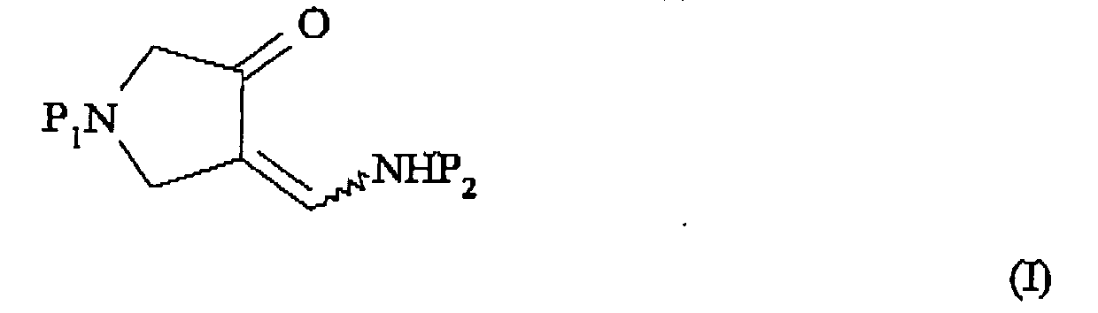

- A process for the production of a compound of formula (IA):


- A process as claimed in claim 1 or 2 wherein protection of the compound of formula (I) or (IA) is performed by reacting the compound of formula (I) or (IA) with a reagent for introducing the amino-protecting group P2, in the presence of a base.
- A process as claimed in claim 3 wherein the reagent for introducing the ammo-protecting group is t-butoxycarbonyl anhydride.
- A process as claimed in claim 3 or 4, wherein the reagent for introducing the amino-protecting group is an isopropanol/water solution.
- A process as claimed in any of claims 1 to 5, wherein P1 and P2 are amino protecting groups removable by acidic conditions.
- A process as claimed in any of claims 1 to 5, wherein the protecting group P1 and/or the protecting group P2 is formyl, acetyl, trifluoroacetyl, benzoyl, para-toluenesulfonyl, methoxycarbonyl, ethoxycarbonyl, t-butoxycarbonyl, benzyloxycarbonyl, para-methylbenzyloxycarbonyl, trichloroethoxycarbonyl, beta-iodoethoxycarbonyl, benzyl, para-methoxybenzyl, trityl, tetrahydropyranyl or pivaloyl.
- A process as claimed in any one of claims 1 to 5 wherein P1 and P2 are both t-butyloxycarbonyl.
- A process as claimed in any one of claims 3 to 8 wherein the base is aqueous potassium hydroxide solution.
- A process as claimed in claim 9 wherein the base is 30% w/w to 50% aqueous potassium hydroxide solution.
- A process as claimed in any one of claims 1 to 10 which is carried out using isopropanol/water as solvent.
- A process as claimed in any of claims 3 to 11, wherein in the continuous operation mode, a stream of aqueous base and a stream of a solution of the 1-(N-protected)-4-aminomethylene-pyrrolidin-3-one of formula (II) or (IIA) containing the reagent for introducing the amino-protecting group are brought together prior to quenching in acid.
- A process as claimed in any preceding claims, which is conducted at a temperature of less than 20°C.
- A process according to any preceding claim wherein the process is conducted in reaction equipment adapted for use in continuous processing mode and comprising a substantially tubular reactor to form the product of formula (I) or (IA) and in which or upstream of which two or more streams of the reagents/starting materials are brought together.
- A process according to any preceding claim wherein the process is conducted in reaction equipment adapted for use in continuous processing mode, and wherein the mixing time in the reaction equipment is shorter than the reaction half life (the time required to reach 50% conversion).
- A process according to any preceding claim wherein the process is conducted in reaction equipment adapted for use in continuous processing mode and in which mixing is induced passively through the fluid flow.
- A process according to any preceding claim wherein the plug flow reactor comprises a jacketed tubular reactor fitted inside with internal mixing elements which continually split and remix the reaction streams promoting mass and heat transfer, whereby a uniform plug flow profile with turbulent fluid flow is achieved.
- A process as claimed in claim 18, 19 or 20, wherein one or more of the static mixers or the plug flow reactor comprises one or more static mixing elements, wherein some, most or all of the mixing elements are adapted to split and mix a fluid stream flowing therethrough substantially in one dimension transverse to the fluid flow.
- A process as claimed in any preceding claim, wherein one or more of the static mixers or the plug flow reactor comprises one or more static mixing elements, wherein some, most or all of the mixing elements comprise a plurality of stacked corrugated sheets, wherein the grooves of each corrugated sheet are transverse to the grooves of any directly adjacent corrugated sheet.
- A process as claimed in claim 19, wherein a plurality of the mixing elements are substantially axially aligned within a or the substantially tubular reactor, with the corrugated sheets arranged so as to allow fluid flow longitudinally along the tubular reactor.
- A process as claimed in claim 20, wherein some or all of the mixer elements in the tubular reactor are statically arranged so as to be in a rotated orientation about the longitudinal axis relative to one or both of the neighbouring mixing elements.
- A process as claimed in any preceding claim, wherein one or more of the static mixers comprise one or more mixing elements arranged substantially axially within and in substantially static relation to a substantially tubular reactor, and wherein the mixing elements define at least one substantially helical fluid flow path in the axial direction between the mixing element and the inner circumferential walls of the tubular reactor.
- A process as claimed in claim 22 wherein two substantially helical fluid flow paths are defined by the mixing elements.
- A process as claimed in claim 22 or 23 wherein the mixing elements are helically-twisted about their axis so as to define the at least one substantially helical fluid flow path.
- A process as claimed in claim 24, wherein wherein one or more (e.g. all) of the static mixers comprise a series of alternating right- and left-handed helically-twisted mixing elements, i.e. having alternating rotational directions.
- A process as claimed in any of claims 22 to 25, wherein each or most mixing element(s) is/are a plate and a leading edge of each element is located substantially perpendicularly to a trailing edge of the following element.
- A process as claimed in any preceding claim, wherein the residence time is about 5 to about 60 seconds.
- A process as claimed in claim 27, wherein the residence time is 10 to 30 seconds.
- A process as claimed in any of claims 22 to 28 as dependent on at least claim 2, wherein the base is used at a stoichiometry of ≥6 equivalents relative to the compound of formula (II) or (IIA).
- A process as claimed in any of claims 22 to 29 as dependent on at least claim 3, wherein the base is used at a stoichiometry of 5 to 12 equivalents relative to the compound of formula (II) or (IIA).
- A process as claimed in any preceding claim wherein two, three or more streams of the reagents/starting materials are brought together upstream of a or the reactor (a) by a direct junction which contains substantially no mixing chamber at the junction, or (b) by a stream-mixing means comprising a substantial mixing chamber having two, three or more reagent inlets in fluid communication with the stored reagents and an outlet in fluid communication with the reactor.
- A process as claimed in claim 31 wherein the stream-mixing means comprises a substantial mixing chamber and is a vortex mixer adapted to mix at least partly the reagent streams in use by generation of a vortex in the mixing chamber and/or in the outlet.
- A process as claimed in claim 31 or 32 wherein the stream-mixing means is at a temperature of about 0 °C to about -15 °C, preferably about -5 °C to about -15 °C.
- A process for the production of a compound of formula (III), or a pharmaceutically acceptable salt and/or hydrate thereof:
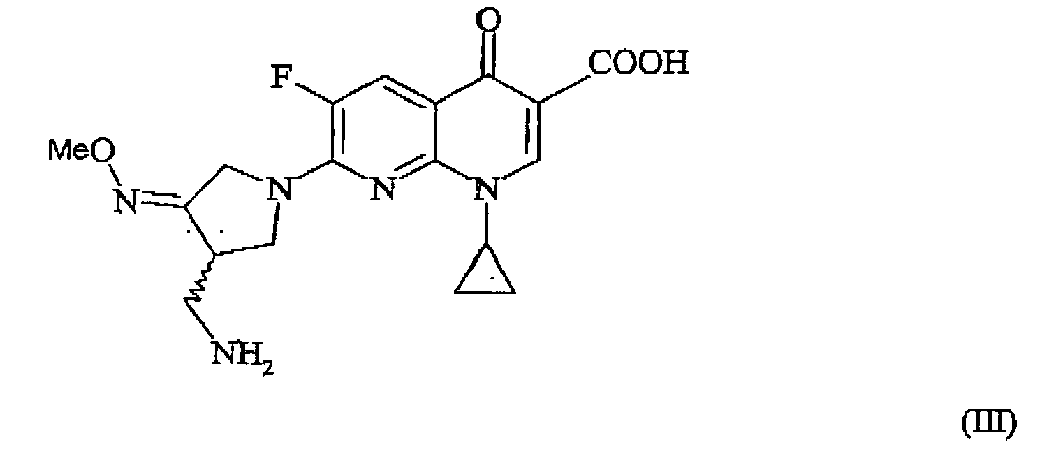 producing a compound of formula (I) or (IA) according to a process as claimed in any preceding claim; andconverting a compound of formula (I) or (IA) to a compound of formula (IV):or a salt thereof, followed by reaction of the compound of formula (IV) or a salt thereof, with a compound of formula (V):

optionally forming a pharmaceutically acceptable salt and/or hydrate thereof. - A process as claimed in claim 34 wherein the reaction of the compound of formula (IV) and the compound of formula (V) is conducted in a solvent in the presence of a base.
- A process as claimed in claim 34 or 35 wherein the compound of formula (III) is (R,S)-7-(3-aminomethyl-4-syn-methoxyimino-pyrrolidin-1-yl)-1-cyclopropyl-6-fluoro-4-oxo-1,4-dihydro-1,8-naphthyridine-3-carboxylic acid methanesulfonate or a hydrate thereof.
- A process as claimed in claim 36 wherein the compound of formula (III) is (R,S)-7-(3-aminomethyl-4-syn-methoxyimino-pyrrolidin-1-yl)-1-cyclopropyl-6-fluoro-4-oxo-1,4-dihydro-1,8-naphthyridine-3-carboxylic acid methanesulfonate sesquihydrate.
Priority Applications (2)
| Application Number | Priority Date | Filing Date | Title |
|---|---|---|---|
| SI200230778T SI1412078T1 (en) | 2001-08-02 | 2002-08-02 | Processes for the production of amino-protected derivatives of 4-aminomethylene-pyrrolidin-3-one, gemifloxacin or a salt thereof |
| CY20091100007T CY1108812T1 (en) | 2001-08-02 | 2009-01-08 | PROCEDURES FOR THE PRODUCTION OF AMINO - PROTECTED PRODUCERS OF 4-AMINOMYTHYLENE-PYRROLIDIN-3-ONE, GEMIFLOXAKINIS OR A SAL |
Applications Claiming Priority (5)
| Application Number | Priority Date | Filing Date | Title |
|---|---|---|---|
| GB0118938 | 2001-08-02 | ||
| GB0118938A GB0118938D0 (en) | 2001-08-02 | 2001-08-02 | Novel process |
| GB0217637 | 2002-07-30 | ||
| GB0217637A GB0217637D0 (en) | 2002-07-30 | 2002-07-30 | Novel processes |
| PCT/GB2002/003585 WO2003011450A1 (en) | 2001-08-02 | 2002-08-02 | Processes for the production of amino-protected derivatives of 4-aminomethylene-pyrrolidin-3-one and/or 4-aminomethylene-pyrrolidin-3-alkoxyimino derivatives and/or gemifloxacin or a salt thereof |
Publications (2)
| Publication Number | Publication Date |
|---|---|
| EP1412078A1 EP1412078A1 (en) | 2004-04-28 |
| EP1412078B1 true EP1412078B1 (en) | 2008-10-08 |
Family
ID=26246399
Family Applications (1)
| Application Number | Title | Priority Date | Filing Date |
|---|---|---|---|
| EP02755123A Expired - Lifetime EP1412078B1 (en) | 2001-08-02 | 2002-08-02 | Processes for the production of amino-protected derivatives of 4-aminomethylene-pyrrolidin-3-one, gemifloxacin or a salt thereof |
Country Status (12)
| Country | Link |
|---|---|
| US (1) | US7199242B2 (en) |
| EP (1) | EP1412078B1 (en) |
| JP (1) | JP2005500350A (en) |
| KR (1) | KR100892864B1 (en) |
| AT (1) | ATE410225T1 (en) |
| CY (1) | CY1108812T1 (en) |
| DE (1) | DE60229255D1 (en) |
| DK (1) | DK1412078T3 (en) |
| ES (1) | ES2314082T3 (en) |
| PT (1) | PT1412078E (en) |
| SI (1) | SI1412078T1 (en) |
| WO (1) | WO2003011450A1 (en) |
Families Citing this family (12)
| Publication number | Priority date | Publication date | Assignee | Title |
|---|---|---|---|---|
| KR100653334B1 (en) * | 2003-03-07 | 2006-12-04 | 주식회사 엘지생명과학 | Novel Production Method of 4-aminomethyl-3-alkoxyiminopyrrolidine methanesulfonate |
| JPWO2006030952A1 (en) * | 2004-09-17 | 2008-05-15 | 株式会社荏原製作所 | Fluid mixer |
| EP1891037A1 (en) * | 2005-06-15 | 2008-02-27 | Hetero Drugs Limited | Gemifloxacin process and polymorphs |
| US7902227B2 (en) | 2007-07-27 | 2011-03-08 | Janssen Pharmaceutica Nv. | C-7 isoxazolinyl quinolone / naphthyridine derivatives useful as antibacterial agents |
| KR100894889B1 (en) * | 2007-12-17 | 2009-04-30 | 삼성전기주식회사 | Discharge device with stirring function |
| JP5604038B2 (en) * | 2008-08-25 | 2014-10-08 | 株式会社日立製作所 | Reaction apparatus and reaction plant |
| CN104693088B (en) * | 2013-12-06 | 2018-01-05 | 常州市勇毅生物药业有限公司 | A kind of preparation method of gemifloxacin side chain |
| US10159953B2 (en) | 2015-11-12 | 2018-12-25 | Uop Llc | Reactor for use with an ionic liquid catalyst |
| US12257560B2 (en) | 2019-04-25 | 2025-03-25 | Jgc Japan Corporation | Fluid mixing unit with meandering flow through partitions of a porous body |
| CA3164365A1 (en) * | 2019-12-19 | 2021-06-24 | Commonwealth Scientific And Industrial Research Organisation | Preparation of halogenated alkoxyethane |
| CN113773240B (en) * | 2021-10-12 | 2022-05-31 | 北京阳光诺和药物研究股份有限公司 | Preparation method of gemifloxacin side chain compound |
| CN114349676B (en) * | 2022-03-21 | 2022-09-02 | 凯莱英生命科学技术(天津)有限公司 | Method for continuously synthesizing N-Boc-2, 5-pyrroline |
Family Cites Families (28)
| Publication number | Priority date | Publication date | Assignee | Title |
|---|---|---|---|---|
| DE59104667D1 (en) | 1990-08-23 | 1995-03-30 | Sulzer Chemtech Ag | Static laminar mixing device, mixing device, and use of mixing device and mixing device. |
| EP0478497B1 (en) | 1990-09-19 | 1994-03-30 | Sulzer Chemtech AG | Static mixer with tubelike housing |
| JP2851454B2 (en) | 1991-06-18 | 1999-01-27 | 三井化学株式会社 | Method for producing phenoxyamines |
| EP0546989B1 (en) | 1991-12-10 | 1995-11-15 | Sulzer Chemtech AG | Static mixing element with guiding faces |
| GB9320455D0 (en) | 1993-10-05 | 1993-11-24 | Atomic Energy Authority Uk | Vortex mixer |
| EP0655275B1 (en) | 1993-11-26 | 1999-10-06 | Sulzer Chemtech AG | Static mixing device |
| GB9401969D0 (en) | 1994-02-02 | 1994-03-30 | Smithkline Beecham Plc | Process |
| KR0168987B1 (en) | 1994-04-22 | 1999-03-20 | 고다 시게노리 | Method for preparing a substituted amine |
| EP0688772B1 (en) | 1994-06-16 | 1999-05-06 | LG Chemical Limited | Quinoline carboxylic acid derivatives having 7-(4-amino-methyl-3-oxime) pyrrolidine substituents and processes for their preparation |
| US5776944A (en) * | 1994-06-16 | 1998-07-07 | Lg Chemical Ltd. | 7-(4-aminomethyl-3-methyloxyiminopyrroplidin-1-yl)-1-cyclopropyl-6-flu oro-4-oxo-1,4-dihydro-1,8-naphthyridine-3-carboxylic acid and the process for the preparation thereof |
| IT234996Y1 (en) * | 1994-06-22 | 2000-03-31 | Bocchiotti Soc Ind Elettrotec | PACKAGING FOR METAL PROFILES. |
| ES2132575T3 (en) | 1995-02-02 | 1999-08-16 | Sulzer Chemtech Ag | STATIC MIXER FOR VERY VISCOUS LIQUIDS. |
| ES2155509T3 (en) | 1995-06-21 | 2001-05-16 | Sulzer Chemtech Ag | TUBE SHAPED BODY MIXER. |
| DE59505850D1 (en) | 1995-08-30 | 1999-06-10 | Sulzer Chemtech Ag | Static mixer for viscous fluids |
| EP0800857B1 (en) | 1996-04-12 | 2003-07-30 | Sulzer Chemtech AG | Mixer tube for low viscosity fluids |
| DE59605822D1 (en) | 1996-07-05 | 2000-10-05 | Sulzer Chemtech Ag Winterthur | Static mixer |
| MA24500A1 (en) | 1997-03-21 | 1998-10-01 | Lg Life Sciences Ltd | CARBOXYLIC ACID SALT DERIVATIVE FROM NAPHTHYRIDINE. |
| KR100286874B1 (en) * | 1998-03-04 | 2001-04-16 | 성재갑 | Method for preparing protected 4-aminomethyl-pyrrolidone-3-on |
| GB9820405D0 (en) | 1998-09-18 | 1998-11-11 | Smithkline Beecham Plc | Process |
| GB9905512D0 (en) | 1999-03-10 | 1999-05-05 | Smithkline Beecham Plc | Process |
| PT1223935E (en) | 1999-06-29 | 2008-04-03 | Lg Life Sciences Ltd | Use of gemifloxacin compounds against bacteria |
| AU6947900A (en) | 1999-09-01 | 2001-03-26 | Smithkline Beecham Corporation | Methods of use of fluoroquinolone compounds against bacteria |
| GB9920917D0 (en) | 1999-09-03 | 1999-11-10 | Sb Pharmco Inc | Novel process |
| GB9920919D0 (en) | 1999-09-03 | 1999-11-10 | Sb Pharmco Inc | Novel compound |
| JP2001081071A (en) | 1999-09-10 | 2001-03-27 | Nippon Soda Co Ltd | Production of phenoxyamines |
| EP1242079A4 (en) | 1999-09-22 | 2003-01-22 | Smithkline Beecham | Methods of use of fluoroquinolone compounds againts bacteria |
| GB9925934D0 (en) | 1999-11-03 | 1999-12-29 | Glaxo Group Ltd | Novel apparatus and process |
| KR100517638B1 (en) * | 2002-04-08 | 2005-09-28 | 주식회사 엘지생명과학 | New process for preparing acid salts of Gemifloxacin |
-
2002
- 2002-08-02 PT PT02755123T patent/PT1412078E/en unknown
- 2002-08-02 SI SI200230778T patent/SI1412078T1/en unknown
- 2002-08-02 EP EP02755123A patent/EP1412078B1/en not_active Expired - Lifetime
- 2002-08-02 DE DE60229255T patent/DE60229255D1/en not_active Expired - Lifetime
- 2002-08-02 DK DK02755123T patent/DK1412078T3/en active
- 2002-08-02 AT AT02755123T patent/ATE410225T1/en active
- 2002-08-02 KR KR1020047001612A patent/KR100892864B1/en not_active Expired - Lifetime
- 2002-08-02 ES ES02755123T patent/ES2314082T3/en not_active Expired - Lifetime
- 2002-08-02 US US10/485,488 patent/US7199242B2/en not_active Expired - Lifetime
- 2002-08-02 JP JP2003516675A patent/JP2005500350A/en active Pending
- 2002-08-02 WO PCT/GB2002/003585 patent/WO2003011450A1/en not_active Ceased
-
2009
- 2009-01-08 CY CY20091100007T patent/CY1108812T1/en unknown
Also Published As
| Publication number | Publication date |
|---|---|
| ATE410225T1 (en) | 2008-10-15 |
| WO2003011450A1 (en) | 2003-02-13 |
| CY1108812T1 (en) | 2014-04-09 |
| US7199242B2 (en) | 2007-04-03 |
| EP1412078A1 (en) | 2004-04-28 |
| US20050043546A1 (en) | 2005-02-24 |
| KR20040058170A (en) | 2004-07-03 |
| ES2314082T3 (en) | 2009-03-16 |
| PT1412078E (en) | 2009-01-08 |
| KR100892864B1 (en) | 2009-04-15 |
| JP2005500350A (en) | 2005-01-06 |
| DK1412078T3 (en) | 2009-02-02 |
| DE60229255D1 (en) | 2008-11-20 |
| SI1412078T1 (en) | 2009-04-30 |
Similar Documents
| Publication | Publication Date | Title |
|---|---|---|
| AU2016272537B2 (en) | Process for the preparation of intermediates useful in the preparation of non-ionic contrast agents | |
| US9101903B2 (en) | Modular reactor | |
| US7199242B2 (en) | Processes for the production of amino-protected derivatives of 4-aminomethylene-pyrrolidin-3-one and/or 4-aminomethylene-pyrrolidin-3-alkoxyimino derivatives and/or gemifloxacin or a salt thereof | |
| CN105121401B (en) | The method that itroparaffin is prepared in micro-structured reactor | |
| JP2004525891A (en) | Exothermic reaction system | |
| JP7186792B2 (en) | Method for producing N-alkyl-nitratoethylnitramine | |
| Karimi-Jaberi et al. | Expeditious, four-component synthesis of 1, 4-dihydropyrano [2, 3-c] pyrazole derivatives catalyzed by trichloroacetic acid or ceric sulfate | |
| JP2023514477A (en) | Preparation of halogenated alkoxyethanes | |
| Lei et al. | An efficient synthesis of 2-(trifluoromethyl)-2H-[1, 3] oxazino [2, 3-a] isoquinolines via a three-component cascade approach using a continuous-flow microreactor | |
| EP2948435A1 (en) | Facile method for preparation of 5-nitrotetrazolates using a flow system | |
| CN114315749B (en) | Method for synthesizing aliskiren intermediate by continuous flow microreactor | |
| CN109897010A (en) | A kind of method for continuously synthesizing of 1,2,3- triazole compound | |
| JP2023514798A (en) | Preparation of halogenated alkoxyethanes | |
| Posakony et al. | Fluoroamines via chiral cyclic sulfamidates | |
| CN115124539B (en) | Preparation method of 7-iodopyrrolo [2,1-F ] [1,2,4] triazine-4-amine | |
| CN115837261A (en) | Device and method for continuous flow synthesis of aryl azide compound | |
| CN114853756A (en) | Preparation process of compound Tomivosertib | |
| CN107963977A (en) | Method for preparing α -ketoamide by using micro-reaction device | |
| CN107674043A (en) | A kind of method that Nintedanib intermediate is synthesized using micro passage reaction | |
| US4220601A (en) | Process for the continuous manufacture of 3-nitro-4-acetylamino-toluene and corresponding apparatus | |
| KR20040029390A (en) | Method for the continuous production of 2-bromo-2-nitro-1,3-propanediol | |
| JPH10287644A (en) | Production of lactam under hydrothermal condition in hot water at high temperature | |
| CN114736205A (en) | Preparation method of compound Tomivosertib | |
| JP2025025579A (en) | Method for producing reduced compounds | |
| CN114773268A (en) | Preparation process and equipment of ivabradine intermediate benzoazepine ketone skeleton |
Legal Events
| Date | Code | Title | Description |
|---|---|---|---|
| PUAI | Public reference made under article 153(3) epc to a published international application that has entered the european phase |
Free format text: ORIGINAL CODE: 0009012 |
|
| 17P | Request for examination filed |
Effective date: 20040211 |
|
| AK | Designated contracting states |
Kind code of ref document: A1 Designated state(s): AT BE BG CH CY CZ DE DK EE ES FI FR GB GR IE IT LI LU MC NL PT SE SK TR |
|
| AX | Request for extension of the european patent |
Extension state: AL LT LV MK RO SI |
|
| 17Q | First examination report despatched |
Effective date: 20040510 |
|
| RAP1 | Party data changed (applicant data changed or rights of an application transferred) |
Owner name: LG LIFE SCIENCES LIMITED |
|
| 17Q | First examination report despatched |
Effective date: 20040510 |
|
| RTI1 | Title (correction) |
Free format text: PROCESSES FOR THE PRODUCTION OF AMINO-PROTECTED DERIVATIVES OF 4-AMINOMETHYLENE-PYRROLIDIN-3-ONE, GEMIFLOXACIN OR A SALT THEREOF |
|
| GRAP | Despatch of communication of intention to grant a patent |
Free format text: ORIGINAL CODE: EPIDOSNIGR1 |
|
| GRAS | Grant fee paid |
Free format text: ORIGINAL CODE: EPIDOSNIGR3 |
|
| GRAA | (expected) grant |
Free format text: ORIGINAL CODE: 0009210 |
|
| AK | Designated contracting states |
Kind code of ref document: B1 Designated state(s): AT BE BG CH CY CZ DE DK EE ES FI FR GB GR IE IT LI LU MC NL PT SE SK TR |
|
| AX | Request for extension of the european patent |
Extension state: AL LT LV MK RO SI |
|
| REG | Reference to a national code |
Ref country code: GB Ref legal event code: FG4D |
|
| REG | Reference to a national code |
Ref country code: CH Ref legal event code: EP |
|
| REG | Reference to a national code |
Ref country code: IE Ref legal event code: FG4D |
|
| REF | Corresponds to: |
Ref document number: 60229255 Country of ref document: DE Date of ref document: 20081120 Kind code of ref document: P |
|
| REG | Reference to a national code |
Ref country code: CH Ref legal event code: NV Representative=s name: BOHEST AG |
|
| REG | Reference to a national code |
Ref country code: SE Ref legal event code: TRGR |
|
| REG | Reference to a national code |
Ref country code: PT Ref legal event code: SC4A Free format text: AVAILABILITY OF NATIONAL TRANSLATION Effective date: 20081223 |
|
| REG | Reference to a national code |
Ref country code: GR Ref legal event code: EP Ref document number: 20080403467 Country of ref document: GR |
|
| REG | Reference to a national code |
Ref country code: DK Ref legal event code: T3 |
|
| REG | Reference to a national code |
Ref country code: ES Ref legal event code: FG2A Ref document number: 2314082 Country of ref document: ES Kind code of ref document: T3 |
|
| PLBE | No opposition filed within time limit |
Free format text: ORIGINAL CODE: 0009261 |
|
| STAA | Information on the status of an ep patent application or granted ep patent |
Free format text: STATUS: NO OPPOSITION FILED WITHIN TIME LIMIT |
|
| 26N | No opposition filed |
Effective date: 20090709 |
|
| GBPC | Gb: european patent ceased through non-payment of renewal fee |
Effective date: 20090802 |
|
| PG25 | Lapsed in a contracting state [announced via postgrant information from national office to epo] |
Ref country code: GB Free format text: LAPSE BECAUSE OF NON-PAYMENT OF DUE FEES Effective date: 20090802 |
|
| PGFP | Annual fee paid to national office [announced via postgrant information from national office to epo] |
Ref country code: CH Payment date: 20110701 Year of fee payment: 10 |
|
| PGFP | Annual fee paid to national office [announced via postgrant information from national office to epo] |
Ref country code: MC Payment date: 20120627 Year of fee payment: 11 Ref country code: SK Payment date: 20120625 Year of fee payment: 11 Ref country code: NL Payment date: 20120629 Year of fee payment: 11 Ref country code: CZ Payment date: 20120626 Year of fee payment: 11 Ref country code: IE Payment date: 20120630 Year of fee payment: 11 Ref country code: DK Payment date: 20120627 Year of fee payment: 11 Ref country code: EE Payment date: 20120625 Year of fee payment: 11 |
|
| PGFP | Annual fee paid to national office [announced via postgrant information from national office to epo] |
Ref country code: LU Payment date: 20120702 Year of fee payment: 11 Ref country code: FI Payment date: 20120627 Year of fee payment: 11 Ref country code: GR Payment date: 20120627 Year of fee payment: 11 |
|
| PGFP | Annual fee paid to national office [announced via postgrant information from national office to epo] |
Ref country code: IT Payment date: 20120625 Year of fee payment: 11 |
|
| PGFP | Annual fee paid to national office [announced via postgrant information from national office to epo] |
Ref country code: BE Payment date: 20120629 Year of fee payment: 11 Ref country code: SE Payment date: 20120628 Year of fee payment: 11 |
|
| PGFP | Annual fee paid to national office [announced via postgrant information from national office to epo] |
Ref country code: BG Payment date: 20120704 Year of fee payment: 11 |
|
| PGFP | Annual fee paid to national office [announced via postgrant information from national office to epo] |
Ref country code: DE Payment date: 20120629 Year of fee payment: 11 Ref country code: ES Payment date: 20120709 Year of fee payment: 11 Ref country code: FR Payment date: 20120717 Year of fee payment: 11 |
|
| PGFP | Annual fee paid to national office [announced via postgrant information from national office to epo] |
Ref country code: PT Payment date: 20120203 Year of fee payment: 11 Ref country code: CY Payment date: 20120801 Year of fee payment: 11 |
|
| PGFP | Annual fee paid to national office [announced via postgrant information from national office to epo] |
Ref country code: AT Payment date: 20120628 Year of fee payment: 11 |
|
| REG | Reference to a national code |
Ref country code: PT Ref legal event code: MM4A Free format text: LAPSE DUE TO NON-PAYMENT OF FEES Effective date: 20140203 |
|
| BERE | Be: lapsed |
Owner name: LG LIFE SCIENCES LIMITED Effective date: 20130831 |
|
| REG | Reference to a national code |
Ref country code: NL Ref legal event code: V1 Effective date: 20140301 |
|
| REG | Reference to a national code |
Ref country code: LT Ref legal event code: MM9D Effective date: 20130802 |
|
| REG | Reference to a national code |
Ref country code: CH Ref legal event code: PL Ref country code: DK Ref legal event code: EBP Effective date: 20130831 |
|
| REG | Reference to a national code |
Ref country code: SE Ref legal event code: EUG |
|
| REG | Reference to a national code |
Ref country code: EE Ref legal event code: MM4A Ref document number: E002673 Country of ref document: EE Effective date: 20130831 Ref country code: AT Ref legal event code: MM01 Ref document number: 410225 Country of ref document: AT Kind code of ref document: T Effective date: 20130802 |
|
| REG | Reference to a national code |
Ref country code: GR Ref legal event code: ML Ref document number: 20080403467 Country of ref document: GR Effective date: 20140305 |
|
| PG25 | Lapsed in a contracting state [announced via postgrant information from national office to epo] |
Ref country code: DE Free format text: LAPSE BECAUSE OF NON-PAYMENT OF DUE FEES Effective date: 20140301 Ref country code: EE Free format text: LAPSE BECAUSE OF NON-PAYMENT OF DUE FEES Effective date: 20130831 Ref country code: NL Free format text: LAPSE BECAUSE OF NON-PAYMENT OF DUE FEES Effective date: 20140301 Ref country code: FI Free format text: LAPSE BECAUSE OF NON-PAYMENT OF DUE FEES Effective date: 20130802 Ref country code: LI Free format text: LAPSE BECAUSE OF NON-PAYMENT OF DUE FEES Effective date: 20130831 Ref country code: CH Free format text: LAPSE BECAUSE OF NON-PAYMENT OF DUE FEES Effective date: 20130831 Ref country code: SE Free format text: LAPSE BECAUSE OF NON-PAYMENT OF DUE FEES Effective date: 20130803 Ref country code: SK Free format text: LAPSE BECAUSE OF NON-PAYMENT OF DUE FEES Effective date: 20130802 Ref country code: MC Free format text: LAPSE BECAUSE OF NON-PAYMENT OF DUE FEES Effective date: 20130902 Ref country code: CZ Free format text: LAPSE BECAUSE OF NON-PAYMENT OF DUE FEES Effective date: 20130802 |
|
| REG | Reference to a national code |
Ref country code: SK Ref legal event code: MM4A Ref document number: E 4705 Country of ref document: SK Effective date: 20130802 |
|
| REG | Reference to a national code |
Ref country code: IE Ref legal event code: MM4A |
|
| REG | Reference to a national code |
Ref country code: FR Ref legal event code: ST Effective date: 20140430 |
|
| PG25 | Lapsed in a contracting state [announced via postgrant information from national office to epo] |
Ref country code: AT Free format text: LAPSE BECAUSE OF NON-PAYMENT OF DUE FEES Effective date: 20130802 Ref country code: IT Free format text: LAPSE BECAUSE OF NON-PAYMENT OF DUE FEES Effective date: 20130802 Ref country code: CY Free format text: LAPSE BECAUSE OF NON-PAYMENT OF DUE FEES Effective date: 20130802 Ref country code: GR Free format text: LAPSE BECAUSE OF NON-PAYMENT OF DUE FEES Effective date: 20140305 Ref country code: BE Free format text: LAPSE BECAUSE OF NON-PAYMENT OF DUE FEES Effective date: 20130831 |
|
| REG | Reference to a national code |
Ref country code: SI Ref legal event code: KO00 Effective date: 20140401 |
|
| REG | Reference to a national code |
Ref country code: DE Ref legal event code: R119 Ref document number: 60229255 Country of ref document: DE Effective date: 20140301 |
|
| PG25 | Lapsed in a contracting state [announced via postgrant information from national office to epo] |
Ref country code: PT Free format text: LAPSE BECAUSE OF NON-PAYMENT OF DUE FEES Effective date: 20140203 |
|
| PG25 | Lapsed in a contracting state [announced via postgrant information from national office to epo] |
Ref country code: IE Free format text: LAPSE BECAUSE OF NON-PAYMENT OF DUE FEES Effective date: 20130802 |
|
| PG25 | Lapsed in a contracting state [announced via postgrant information from national office to epo] |
Ref country code: FR Free format text: LAPSE BECAUSE OF NON-PAYMENT OF DUE FEES Effective date: 20130902 Ref country code: BG Free format text: LAPSE BECAUSE OF NON-PAYMENT OF DUE FEES Effective date: 20140630 |
|
| REG | Reference to a national code |
Ref country code: ES Ref legal event code: FD2A Effective date: 20140905 |
|
| PG25 | Lapsed in a contracting state [announced via postgrant information from national office to epo] |
Ref country code: DK Free format text: LAPSE BECAUSE OF NON-PAYMENT OF DUE FEES Effective date: 20130831 Ref country code: BG Free format text: LAPSE BECAUSE OF NON-PAYMENT OF DUE FEES Effective date: 20130831 |
|
| PG25 | Lapsed in a contracting state [announced via postgrant information from national office to epo] |
Ref country code: BG Free format text: LAPSE BECAUSE OF NON-PAYMENT OF DUE FEES Effective date: 20140930 |
|
| PG25 | Lapsed in a contracting state [announced via postgrant information from national office to epo] |
Ref country code: ES Free format text: LAPSE BECAUSE OF NON-PAYMENT OF DUE FEES Effective date: 20130803 |
|
| PG25 | Lapsed in a contracting state [announced via postgrant information from national office to epo] |
Ref country code: LU Free format text: LAPSE BECAUSE OF NON-PAYMENT OF DUE FEES Effective date: 20130802 |
|
| PG25 | Lapsed in a contracting state [announced via postgrant information from national office to epo] |
Ref country code: BG Free format text: LAPSE BECAUSE OF NON-PAYMENT OF DUE FEES Effective date: 20140228 |
|
| PGFP | Annual fee paid to national office [announced via postgrant information from national office to epo] |
Ref country code: TR Payment date: 20210729 Year of fee payment: 20 |