EP1411745A1 - Packet switching for packet data transmission systems in a multi-channel radio arrangement - Google Patents
Packet switching for packet data transmission systems in a multi-channel radio arrangement Download PDFInfo
- Publication number
- EP1411745A1 EP1411745A1 EP02292555A EP02292555A EP1411745A1 EP 1411745 A1 EP1411745 A1 EP 1411745A1 EP 02292555 A EP02292555 A EP 02292555A EP 02292555 A EP02292555 A EP 02292555A EP 1411745 A1 EP1411745 A1 EP 1411745A1
- Authority
- EP
- European Patent Office
- Prior art keywords
- channel
- radio
- failure
- channels
- packet
- Prior art date
- Legal status (The legal status is an assumption and is not a legal conclusion. Google has not performed a legal analysis and makes no representation as to the accuracy of the status listed.)
- Granted
Links
- 230000005540 biological transmission Effects 0.000 title claims abstract description 22
- 238000000034 method Methods 0.000 claims abstract description 15
- 238000004891 communication Methods 0.000 claims description 6
- 230000007246 mechanism Effects 0.000 abstract description 4
- 230000032258 transport Effects 0.000 description 18
- 238000005562 fading Methods 0.000 description 5
- RGNPBRKPHBKNKX-UHFFFAOYSA-N hexaflumuron Chemical compound C1=C(Cl)C(OC(F)(F)C(F)F)=C(Cl)C=C1NC(=O)NC(=O)C1=C(F)C=CC=C1F RGNPBRKPHBKNKX-UHFFFAOYSA-N 0.000 description 5
- 230000015556 catabolic process Effects 0.000 description 4
- 238000006731 degradation reaction Methods 0.000 description 4
- 230000004048 modification Effects 0.000 description 4
- 238000012986 modification Methods 0.000 description 4
- 238000000605 extraction Methods 0.000 description 2
- 238000003780 insertion Methods 0.000 description 2
- 230000037431 insertion Effects 0.000 description 2
- 235000008694 Humulus lupulus Nutrition 0.000 description 1
- 230000001934 delay Effects 0.000 description 1
- 230000001419 dependent effect Effects 0.000 description 1
- 238000001514 detection method Methods 0.000 description 1
- 230000006866 deterioration Effects 0.000 description 1
- 238000010586 diagram Methods 0.000 description 1
- 230000008034 disappearance Effects 0.000 description 1
- 238000013467 fragmentation Methods 0.000 description 1
- 238000006062 fragmentation reaction Methods 0.000 description 1
- 230000009467 reduction Effects 0.000 description 1
- 230000003595 spectral effect Effects 0.000 description 1
Images


Classifications
-
- H—ELECTRICITY
- H04—ELECTRIC COMMUNICATION TECHNIQUE
- H04L—TRANSMISSION OF DIGITAL INFORMATION, e.g. TELEGRAPHIC COMMUNICATION
- H04L1/00—Arrangements for detecting or preventing errors in the information received
- H04L1/22—Arrangements for detecting or preventing errors in the information received using redundant apparatus to increase reliability
-
- H—ELECTRICITY
- H04—ELECTRIC COMMUNICATION TECHNIQUE
- H04L—TRANSMISSION OF DIGITAL INFORMATION, e.g. TELEGRAPHIC COMMUNICATION
- H04L49/00—Packet switching elements
- H04L49/55—Prevention, detection or correction of errors
-
- H—ELECTRICITY
- H04—ELECTRIC COMMUNICATION TECHNIQUE
- H04W—WIRELESS COMMUNICATION NETWORKS
- H04W28/00—Network traffic management; Network resource management
- H04W28/16—Central resource management; Negotiation of resources or communication parameters, e.g. negotiating bandwidth or QoS [Quality of Service]
- H04W28/18—Negotiating wireless communication parameters
- H04W28/20—Negotiating bandwidth
-
- H—ELECTRICITY
- H04—ELECTRIC COMMUNICATION TECHNIQUE
- H04J—MULTIPLEX COMMUNICATION
- H04J2203/00—Aspects of optical multiplex systems other than those covered by H04J14/05 and H04J14/07
- H04J2203/0001—Provisions for broadband connections in integrated services digital network using frames of the Optical Transport Network [OTN] or using synchronous transfer mode [STM], e.g. SONET, SDH
- H04J2203/0028—Local loop
- H04J2203/003—Medium of transmission, e.g. fibre, cable, radio
- H04J2203/0035—Radio
-
- H—ELECTRICITY
- H04—ELECTRIC COMMUNICATION TECHNIQUE
- H04J—MULTIPLEX COMMUNICATION
- H04J2203/00—Aspects of optical multiplex systems other than those covered by H04J14/05 and H04J14/07
- H04J2203/0001—Provisions for broadband connections in integrated services digital network using frames of the Optical Transport Network [OTN] or using synchronous transfer mode [STM], e.g. SONET, SDH
- H04J2203/0057—Operations, administration and maintenance [OAM]
- H04J2203/006—Fault tolerance and recovery
-
- H—ELECTRICITY
- H04—ELECTRIC COMMUNICATION TECHNIQUE
- H04J—MULTIPLEX COMMUNICATION
- H04J2203/00—Aspects of optical multiplex systems other than those covered by H04J14/05 and H04J14/07
- H04J2203/0001—Provisions for broadband connections in integrated services digital network using frames of the Optical Transport Network [OTN] or using synchronous transfer mode [STM], e.g. SONET, SDH
- H04J2203/0073—Services, e.g. multimedia, GOS, QOS
- H04J2203/0082—Interaction of SDH with non-ATM protocols
- H04J2203/0085—Support of Ethernet
-
- H—ELECTRICITY
- H04—ELECTRIC COMMUNICATION TECHNIQUE
- H04J—MULTIPLEX COMMUNICATION
- H04J2203/00—Aspects of optical multiplex systems other than those covered by H04J14/05 and H04J14/07
- H04J2203/0001—Provisions for broadband connections in integrated services digital network using frames of the Optical Transport Network [OTN] or using synchronous transfer mode [STM], e.g. SONET, SDH
- H04J2203/0089—Multiplexing, e.g. coding, scrambling, SONET
- H04J2203/0094—Virtual Concatenation
-
- H—ELECTRICITY
- H04—ELECTRIC COMMUNICATION TECHNIQUE
- H04W—WIRELESS COMMUNICATION NETWORKS
- H04W40/00—Communication routing or communication path finding
Definitions
- the present invention relates to the field of wireless transmissions, both of point-to-point and point-to-multipoint type. More in particular, the present invention relates to multi-channel wireless transmission systems transmitting packet data signals. Still more in particular, the present invention relates to a mechanism operating a novel packet switching.
- multi-channel systems In the field of radio systems, multi-channel systems are known and widely used. In multi-channel protected arrangements a number n of working channels and one (or more) spare channel are provided. Typical configurations are n+1 (n working channels and one protecting channel) or n+2 (n working channels and two protecting channels).
- Typical data packet signals comprise Ethernet or fast Ethernet signals.
- the transport of packet data signals in a multi-channel radio system is performed by means of SDH/SONET Virtual Concatenation. For instance, by using a n+1 radio channel configuration (n working channels + one spare channel for protection), the transport of data frames is performed in the following manner:
- the packet data traffic needs to be switched on the spare channel in order to avoid the loss of the whole traffic distributed on the interested Virtual Container, resulting in that the whole traffic becomes unavailable (the bytes of one frame are distributed among all the virtual containers.
- the above procedure has several disadvantages.
- the first disadvantage is that the system needs further hardware to work. For sure, it needs a switching equipment to provide the protection of the working channels (TX/RX distributors, a controller, ). Furthermore, proper switching criteria should be detected.
- a further disadvantage lies in that the available bandwidth is reduced, due to the need to reserve (at least) one spare channel dedicated to the switching performance.
- a further disadvantage is that, in case of sudden break of one channel (namely a non predictable failure), all the messages whose bytes transit in the fail-affected Virtual Containers will be lost.
- the main object of the present invention is overcoming them and providing a new method and apparatus performing a switching in a packet data transmission system in a multi-channel radio arrangement.
- the problem to solve is how to transport packet data streams (for instance Ethernet frames) by means of two or more SDH/SONET Virtual Containers in a multi-channel radio arrangement.
- a packet switching is implemented.
- the basic idea is to assign the transport of a data packet to a single Virtual Container. This means that different Virtual Containers concurrently transport different frames. With the Virtual Concatenation, all the Virtual Containers concurrently transport the same frame.
- Fig. 1 diagrammatically showing how packet messages are transmitted using virtual concatenation, according to the state of the art.
- packets A, B, C, ..., n
- each one of these packets is distributed among the available working resources/channels.
- the configuration is a "3 + 1" (three working channels and one spare channel)
- packet A is divided (for instance in a bit-by-bit wise) into three portions A1, A2, A3, and each portion is transported through one of the three different working channels (VC-X#1, VC-X#2, VC-X#3).
- the spare channel is not used and it is in a standby status.
- the working channels are shown as gray tubes while the spare/protection channels are white tubes.
- the Virtual Concatenation foresee that a transported message is divided between the different Path composing the Pipe.
- the original message is inserted inside the available VCs assigning a single byte for every available VC until the sending bytes are terminated.
- the receiver In receiving side, the receiver must realign the VCs before the original message is extracted.
- the spare channel When the transmission quality in a channel degrades and a fail is expected, the spare channel is switched on. Such a switching mechanism is hitless and no packets is lost.
- the packet frames are received by a corresponding RX switching equipment RXSW providing its output to a frame re-ordering block 16.
- the frame re-ordering block 16 in its turn, feeds a queue of outgoing frames block 18 whose output are the original packet frame signals.
- the TX and RX switching equipments TXSW, RXSW are shown in greater detail in Fig. 6.
- the TX switching equipment further comprises a TX distributor 20 and n hybrid components 221, 222, 223. Both the TX distributor 20 and hybrid components 221-223 are fed by the dispatcher of frames block 14 and feed the respective TX apparatus TX1 - TX4.
- the hybrid components 221-223 bridge the received data packets to the TX distributor 20 so that, in case of failure, the TX apparatus TX4 of the spare channel #4 will be able to replace the TX apparatus of the failed channel.
- the RX switching equipment further comprises a RX distributor 24.
- the output of the radio RX apparatuses RX1-RX3 feed a hitless switch 26 connected with the RX distributor 24.
- the switching system In order to operate as a countermeasure against multipath fading, the switching system must operate in a truly "error free hitless" mode, preserving the "bit count integrity" of the output bit stream, and the overall switching time must be short enough to counteract fast fading events.
- the TX distributor 20 bridges the protection channel to the failure affected channel.
- one or p (p>1) protection radio channels are prepared for n working channels.
- the signal in the interrupted channel will immediately be recovered by one of the protection channels over m radio hops.
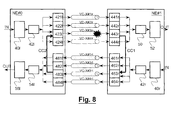
- the incoming packet data frames (for instance a sequence of frames labelled as A, B, C, D, E, etc..) are stored into a queue buffer 40l providing them to a dispatcher 421.
- the dispatcher 42l provides its output to four (one for each channel) path source functional blocks 421l, 422l, 4231, 4241 that manage the insertion of a packet data frame into a Virtual Container.
- path sink functional blocks 441 r, 442r, 443r, 444r that manage the extraction of a packet data frame from a Virtual Container, a block 50 for reordering the received frames and a queue buffer 52.
- the "I" suffix of blocks of Network Element #0 stands for "left"; the "r” suffix of blocks of Network Element #1 stands for "right".
- NE#1 is provided with a queue buffer 40r, a dispatcher 42r and four path source functional blocks 461 r, 462r, 463r, 464r.
- NE#0 there are four path sink functional blocks 481l, 482l, 4831, 4841, a block 54 for reordering the received frames and a queue buffer 56.
- a Virtual Container e.g. VC #3
- the remaining Virtual Containers i.e. VC #1, VC#2 and VC#4
- a failure on a working channel does not lead to the complete loss of the traffic but just to a bandwidth reduction.
- Path source (421l-424l; 461r-464r)
- Path sink (441r-444r; 481l-484l).
- Path sink 443r detects the failure and provides the related information to Path source 463r through a proper communication channel CC1; the transmission of packet data frames on VC-X #3rl is disabled and just status information are forwarded to Path sink 4831 by means of the VC-X #3rl itself.
- Path sink 4831 receives the failure information from Path sink 4831 and forwarded to Path source 4231 through a proper communication channel CC2.
- Path source 4231 in its turn, disables the transmission of packet data frames.
- the VC-X #3 is completely disabled in both directions and this condition will remain until the disappearance of failure detection.
- the occupied bandwidth dimension is dynamically modified in order to recover from a failure.
- the dynamic modification of the spectral occupation can be performed also in absence of failure just to increase/decrease the link capability; this feature is performed by the same communication channels CC1, CC2 already described and without any loss of packet data frames.
- the present invention provides the following main advantages:
Landscapes
- Engineering & Computer Science (AREA)
- Computer Networks & Wireless Communication (AREA)
- Signal Processing (AREA)
- Quality & Reliability (AREA)
- Mobile Radio Communication Systems (AREA)
- Data Exchanges In Wide-Area Networks (AREA)
Abstract
Description
- the bytes of one frame are distributed among all the SDH/SONET Virtual Containers and transmitted through the n working channels;
- a dedicated radio channel is reserved for the protected configuration of the system against atmospheric phenomena of attenuation, reflections or radio channel noise;
- due to the fact that the SDH/SONET Virtual Containers can follow different paths, at the ending point the Virtual Containers should be re-aligned;
- the bytes of the data frames are extracted from the re-aligned Virtual Containers and the frame is re-assembled.
- Fig. 1 diagrammatically shows how packet messages are sent using virtual concatenation, according to the state of the art;
- Fig. 2 shows the arrangement of Fig. 1 in case of a sudden break of a channel;
- Fig. 3 diagrammatically shows how packet messages are sent using the packet switching mechanism according to the present invention;
- Fig. 4 shows the arrangement of Fig. 3 in case of a sudden break of a channel;
- Fig. 5 shows in greater detail how a multi-channel radio system for transmitting packet frame signals could be implemented according to the state of the art;
- Fig. 6 shows the multi-channel switching arrangement, both TX and RX sides, that is used in the system of Fig. 5;
- Fig. 7 shows the multi-channel packet-data switching arrangement according to the present invention; and
- Fig. 8 shows the arrangement of Fig. 7 in case of failure.
- all the bandwidth is used to transport every single message;
- if a VC payload is lost, the whole message is lost;
- it is necessary to provide the VCs re-alignment before extracting the message.
- the switching system must compensate for the different and time-varying transmission delays on the working channel and on the protection channel: a fast delay adjustment procedure is required before switching.
- the overall switching sequence must be completed before the "outage BER" threshold is reached.
- a single Path is used to transport a single message;
- in case of a sudden break of a channel (see Fig. 4), the other messages sent over the other Paths of the same Pipe are considered "valid", because the data transported by every Path are un-correlated from those transported by the other Path of the same Pipe. Obviously, in case of a degradation of a channel, a full hitless switch is performed and no packets are lost.
- it is necessary a re-ordering of the messages transported by different Path, to restore the original sequence.
- The system does not require a dedicated spare channel to protect a single working channel transporting a VC against degradation or failure of the radio channel. This results in an efficient bandwidth utilisation for data traffic, because all the assigned channels of the channelling arrangement can be used for the transmission.
- No switching equipment or algorithm is necessary for protection operation.
- In case of failure of one Virtual Container, the bandwidth is reduced (to the same level as in the prior art) but the traffic is not completely lost.
- A dynamic modification of the pipe dimension without any traffic loss is possible.
Claims (7)
- Method for transmitting/receiving data packet frames in a multi-channel wireless transmission system, the method comprising the steps of receiving a plurality of data packets (A, B, C, ...) to be transmitted; and providing a number (n and p) of radio channels (VC-X#1, VC-X#2, ...) for performing the transmission, the radio channels including one or more working channels (n) and one or more protection channels (p), characterized by the steps of assigning the entire transport of each data packet (A, B, C, ...) to one radio channel (VC-X#1, VC-X#2, ...) and, in absence of failures, performing the transmission by using all the available working and protection channels.
- Method according to claim 1, characterized by the step of, in case a radio channel becomes affected by a failure in at least one direction, disabling the failure-affected channel (VC-X#3lr) in the opposite direction and assigning the entire transport of each of the further single data packets (A, B, C, ...) to corresponding single radio channels (VC-X#1, VC#X-2, ...) of the remaining unfailed radio channels.
- Method according to claim 2, characterized in that the step of disabling the failure-affected channel comprises the steps of: detecting that a channel has become affected by a failure; communicating (443r), through a first communication channel (CC1), the channel failure to a corresponding path source block (463r); transferring the failure information to the corresponding path sink block (483l); and finally forwarding the failure information to the path source block (423l) of the transmitting side through a second communication channel (CC2).
- Method according to any of the preceding claims, characterized by the step, at the transmitting side, of attaching a sequence label/number to every data packet (A, B, C, ...) that is transmitted and, at the receiving side, of reordering the data packets according to the proper sequence label/number.
- Apparatus for transmitting/receiving data packet frames in a multi-channel wireless transmission system comprising a number (n and p) of radio channels (VC-X#1, VC-X#2, ...) for performing the transmission, the radio channels including at least one working channel and at least one protection channel, the apparatus (NE#0, NE#1) comprising interfaces for receiving a plurality of data packets (A, B, C, ...) to be radio transmitted and interfaces for outputting packets that have been received from a remote radio apparatus; a number (n and p) of transmitters (421l-424l; 461r-464r); and a corresponding number (n and p) of receivers (441r-444r; 481l-484l), characterized by further comprising a dispatcher (421; 42r) for assigning each packet (A, B, C, ...) to a transmitter so that the entire transport of each data packet (A, B, C, ...) is made by one radio channel (VC-X#1, VC-X#2, ...) and in that, in absence of failures, the transmission is performed by using all the available working and protection channels.
- Apparatus according to claim 5, characterized in that it further comprises a communication channel (CC1; CC2) from reporting channel failure information between a transmitter (421l-424l; 461r-464r) and a receiver (441 r-444r; 481l-484l).
- Apparatus according to claim 1 or 2, characterized in that means are provided in the transmitting side for attaching a sequence label/number to every data packet (A, B, C, ...) that is transmitted and, in the receiving side, for reordering the data packets according to the proper sequence label/number.
Priority Applications (4)
| Application Number | Priority Date | Filing Date | Title |
|---|---|---|---|
| EP02292555A EP1411745B1 (en) | 2002-10-16 | 2002-10-16 | Packet switching for packet data transmission systems in a multi-channel radio arrangement |
| AT02292555T ATE369717T1 (en) | 2002-10-16 | 2002-10-16 | PACKET SWITCHING FOR PACKET DATA TRANSMISSION SYSTEMS IN A MULTI-CHANNEL RADIO ARRANGEMENT |
| DE60221669T DE60221669T2 (en) | 2002-10-16 | 2002-10-16 | Packet switching for packet data transmission systems in a multi-channel radio arrangement |
| US10/685,430 US20040081081A1 (en) | 2002-10-16 | 2003-10-16 | Packet switching for packet data transmission systems in a multi-channel radio arrangement |
Applications Claiming Priority (1)
| Application Number | Priority Date | Filing Date | Title |
|---|---|---|---|
| EP02292555A EP1411745B1 (en) | 2002-10-16 | 2002-10-16 | Packet switching for packet data transmission systems in a multi-channel radio arrangement |
Publications (2)
| Publication Number | Publication Date |
|---|---|
| EP1411745A1 true EP1411745A1 (en) | 2004-04-21 |
| EP1411745B1 EP1411745B1 (en) | 2007-08-08 |
Family
ID=32039234
Family Applications (1)
| Application Number | Title | Priority Date | Filing Date |
|---|---|---|---|
| EP02292555A Expired - Lifetime EP1411745B1 (en) | 2002-10-16 | 2002-10-16 | Packet switching for packet data transmission systems in a multi-channel radio arrangement |
Country Status (4)
| Country | Link |
|---|---|
| US (1) | US20040081081A1 (en) |
| EP (1) | EP1411745B1 (en) |
| AT (1) | ATE369717T1 (en) |
| DE (1) | DE60221669T2 (en) |
Cited By (1)
| Publication number | Priority date | Publication date | Assignee | Title |
|---|---|---|---|---|
| EP2717529A4 (en) * | 2011-05-31 | 2014-11-12 | Nec Corp | Wireless transmission device, wireless transmission system, and method for controlling wireless transmission device |
Families Citing this family (21)
| Publication number | Priority date | Publication date | Assignee | Title |
|---|---|---|---|---|
| US7411900B2 (en) * | 2003-05-28 | 2008-08-12 | Lucent Technologies Inc. | Fast restoration for virtually-concatenated data traffic |
| JP2005347943A (en) | 2004-06-01 | 2005-12-15 | Hitachi Ltd | Network relay device and control method thereof |
| US7922702B2 (en) | 2004-07-02 | 2011-04-12 | Qlt Inc. | Treatment medium delivery device and methods for delivery of such treatment mediums to the eye using such a delivery device |
| US7782805B1 (en) | 2005-02-08 | 2010-08-24 | Med Belhadj | High speed packet interface and method |
| KR101223870B1 (en) * | 2006-03-03 | 2013-01-17 | 삼성전자주식회사 | Concurrent transmission method over multiple radio links |
| US7796708B2 (en) | 2006-03-29 | 2010-09-14 | Provigent Ltd. | Adaptive receiver loops with weighted decision-directed error |
| SG170816A1 (en) | 2006-03-31 | 2011-05-30 | Qlt Plug Delivery Inc | Drug delivery methods, structures, and compositions for nasolacrimal system |
| US7643512B2 (en) * | 2006-06-29 | 2010-01-05 | Provigent Ltd. | Cascaded links with adaptive coding and modulation |
| US7839952B2 (en) * | 2006-12-05 | 2010-11-23 | Provigent Ltd | Data rate coordination in protected variable-rate links |
| US7720136B2 (en) * | 2006-12-26 | 2010-05-18 | Provigent Ltd | Adaptive coding and modulation based on link performance prediction |
| US8315574B2 (en) | 2007-04-13 | 2012-11-20 | Broadcom Corporation | Management of variable-rate communication links |
| US7821938B2 (en) | 2007-04-20 | 2010-10-26 | Provigent Ltd. | Adaptive coding and modulation for synchronous connections |
| US8001445B2 (en) | 2007-08-13 | 2011-08-16 | Provigent Ltd. | Protected communication link with improved protection indication |
| US9011361B2 (en) | 2007-09-07 | 2015-04-21 | Mati Therapeutics Inc. | Lacrimal implant detection |
| US8040985B2 (en) | 2007-10-09 | 2011-10-18 | Provigent Ltd | Decoding of forward error correction codes in the presence of phase noise |
| WO2010011500A1 (en) * | 2008-07-25 | 2010-01-28 | Smith International, Inc. | Pdc bit having split blades |
| US8135972B2 (en) * | 2009-03-10 | 2012-03-13 | Cortina Systems, Inc. | Data interface power consumption control |
| CN101645797B (en) | 2009-08-25 | 2011-04-13 | 华为技术有限公司 | Automatic protective switching method, equipment and system |
| IL204515A (en) * | 2010-03-16 | 2014-06-30 | Amir Ilan | Method and apparatus for reducing delays in a packets switched network |
| WO2012037970A1 (en) | 2010-09-21 | 2012-03-29 | Nokia Siemens Networks Oy | Method and network devices for splitting of a data stream |
| TWI504174B (en) * | 2011-06-28 | 2015-10-11 | Mstar Semiconductor Inc | Wireless transmission method and wireless transmission system |
Citations (2)
| Publication number | Priority date | Publication date | Assignee | Title |
|---|---|---|---|---|
| EP0157412A2 (en) * | 1984-04-02 | 1985-10-09 | Nec Corporation | Radio communication system |
| EP0982900A2 (en) * | 1998-08-27 | 2000-03-01 | Nortel Networks Corporation | Frame based data over synchronous digital hierarchy network |
Family Cites Families (6)
| Publication number | Priority date | Publication date | Assignee | Title |
|---|---|---|---|---|
| US5400163A (en) * | 1990-11-21 | 1995-03-21 | Mitsubishi Denki Kabushiki Kaisha | Multiplex digital communication system for transmitting channel identification information |
| US6389039B1 (en) * | 1998-10-22 | 2002-05-14 | Telefonaktiebolaget Lm Ericsson (Publ) | Asynchronous transfer on the cellular radio link |
| JP3546765B2 (en) * | 1999-07-09 | 2004-07-28 | 日本電気株式会社 | Packet transfer method and system |
| JP4427196B2 (en) * | 2001-02-07 | 2010-03-03 | 株式会社日立製作所 | IP packet communication apparatus and redundant configuration switching method |
| US6973058B2 (en) * | 2001-07-31 | 2005-12-06 | Broadcom Corporation | System and method for accessing a multi-line gateway using cordless telephony terminals |
| US7110421B2 (en) * | 2001-11-28 | 2006-09-19 | Sony Corporation | System and method for transmitting information over multiple channels |
-
2002
- 2002-10-16 DE DE60221669T patent/DE60221669T2/en not_active Expired - Fee Related
- 2002-10-16 AT AT02292555T patent/ATE369717T1/en not_active IP Right Cessation
- 2002-10-16 EP EP02292555A patent/EP1411745B1/en not_active Expired - Lifetime
-
2003
- 2003-10-16 US US10/685,430 patent/US20040081081A1/en not_active Abandoned
Patent Citations (2)
| Publication number | Priority date | Publication date | Assignee | Title |
|---|---|---|---|---|
| EP0157412A2 (en) * | 1984-04-02 | 1985-10-09 | Nec Corporation | Radio communication system |
| EP0982900A2 (en) * | 1998-08-27 | 2000-03-01 | Nortel Networks Corporation | Frame based data over synchronous digital hierarchy network |
Cited By (2)
| Publication number | Priority date | Publication date | Assignee | Title |
|---|---|---|---|---|
| EP2717529A4 (en) * | 2011-05-31 | 2014-11-12 | Nec Corp | Wireless transmission device, wireless transmission system, and method for controlling wireless transmission device |
| US9571226B2 (en) | 2011-05-31 | 2017-02-14 | Nec Corporation | Wireless transmission device, wireless transmission system, and method for controlling wireless transmission device |
Also Published As
| Publication number | Publication date |
|---|---|
| EP1411745B1 (en) | 2007-08-08 |
| ATE369717T1 (en) | 2007-08-15 |
| DE60221669D1 (en) | 2007-09-20 |
| DE60221669T2 (en) | 2008-05-21 |
| US20040081081A1 (en) | 2004-04-29 |
Similar Documents
| Publication | Publication Date | Title |
|---|---|---|
| EP1411745B1 (en) | Packet switching for packet data transmission systems in a multi-channel radio arrangement | |
| US6148010A (en) | Method and apparatus for distributing and consolidating data packets onto multiple network interfaces | |
| EP2571190B1 (en) | System and method for selective protection switching | |
| US20210243668A1 (en) | Radio Link Aggregation | |
| US11943651B2 (en) | Fault tolerant transmission for a wireless link | |
| KR101555188B1 (en) | System and method providing resilient data transmission via spectral fragments | |
| JPS5810894B2 (en) | Time division multiple access communication system | |
| US8958377B2 (en) | Transmission device, transmission method and transmission system | |
| US8374147B2 (en) | System and method for protecting payload information in radio transmission | |
| EP2619946B1 (en) | Method and network devices for splitting of a data stream | |
| US20090219809A1 (en) | Redundant mux cnfiguration | |
| US10560392B2 (en) | Wireless communication arrangement with two devices communicating with each other via a radio link in which a common radio interface constitutes a communication protocol for data streams arranged to support a segmentation of data frames | |
| EP2159945B1 (en) | Method for protecting traffic flows in a radio transmission system | |
| WO2022162945A1 (en) | Wireless communication system, wireless communication method, and transmission device | |
| WO2025004251A1 (en) | Wireless communication method, wireless communication system, transmission device, and program | |
| EP1838054A1 (en) | Method of hitless radio protection switching over ethernet and a system for carrying out the method | |
| JPH10200464A (en) | Line change-over system |
Legal Events
| Date | Code | Title | Description |
|---|---|---|---|
| PUAI | Public reference made under article 153(3) epc to a published international application that has entered the european phase |
Free format text: ORIGINAL CODE: 0009012 |
|
| AK | Designated contracting states |
Kind code of ref document: A1 Designated state(s): AT BE BG CH CY CZ DE DK EE ES FI FR GB GR IE IT LI LU MC NL PT SE SK TR |
|
| AX | Request for extension of the european patent |
Extension state: AL LT LV MK RO SI |
|
| 17P | Request for examination filed |
Effective date: 20041021 |
|
| AKX | Designation fees paid |
Designated state(s): AT BE BG CH CY CZ DE DK EE ES FI FR GB GR IE IT LI LU MC NL PT SE SK TR |
|
| 17Q | First examination report despatched |
Effective date: 20050125 |
|
| GRAP | Despatch of communication of intention to grant a patent |
Free format text: ORIGINAL CODE: EPIDOSNIGR1 |
|
| RAP1 | Party data changed (applicant data changed or rights of an application transferred) |
Owner name: ALCATEL LUCENT |
|
| GRAS | Grant fee paid |
Free format text: ORIGINAL CODE: EPIDOSNIGR3 |
|
| GRAA | (expected) grant |
Free format text: ORIGINAL CODE: 0009210 |
|
| AK | Designated contracting states |
Kind code of ref document: B1 Designated state(s): AT BE BG CH CY CZ DE DK EE ES FI FR GB GR IE IT LI LU MC NL PT SE SK TR |
|
| REG | Reference to a national code |
Ref country code: GB Ref legal event code: FG4D |
|
| REG | Reference to a national code |
Ref country code: CH Ref legal event code: EP |
|
| REG | Reference to a national code |
Ref country code: IE Ref legal event code: FG4D |
|
| REF | Corresponds to: |
Ref document number: 60221669 Country of ref document: DE Date of ref document: 20070920 Kind code of ref document: P |
|
| ET | Fr: translation filed | ||
| PG25 | Lapsed in a contracting state [announced via postgrant information from national office to epo] |
Ref country code: FI Free format text: LAPSE BECAUSE OF FAILURE TO SUBMIT A TRANSLATION OF THE DESCRIPTION OR TO PAY THE FEE WITHIN THE PRESCRIBED TIME-LIMIT Effective date: 20070808 Ref country code: BG Free format text: LAPSE BECAUSE OF FAILURE TO SUBMIT A TRANSLATION OF THE DESCRIPTION OR TO PAY THE FEE WITHIN THE PRESCRIBED TIME-LIMIT Effective date: 20071108 Ref country code: ES Free format text: LAPSE BECAUSE OF FAILURE TO SUBMIT A TRANSLATION OF THE DESCRIPTION OR TO PAY THE FEE WITHIN THE PRESCRIBED TIME-LIMIT Effective date: 20071119 Ref country code: NL Free format text: LAPSE BECAUSE OF FAILURE TO SUBMIT A TRANSLATION OF THE DESCRIPTION OR TO PAY THE FEE WITHIN THE PRESCRIBED TIME-LIMIT Effective date: 20070808 |
|
| PGFP | Annual fee paid to national office [announced via postgrant information from national office to epo] |
Ref country code: DE Payment date: 20071025 Year of fee payment: 6 |
|
| NLV1 | Nl: lapsed or annulled due to failure to fulfill the requirements of art. 29p and 29m of the patents act | ||
| REG | Reference to a national code |
Ref country code: CH Ref legal event code: PL |
|
| PG25 | Lapsed in a contracting state [announced via postgrant information from national office to epo] |
Ref country code: LI Free format text: LAPSE BECAUSE OF FAILURE TO SUBMIT A TRANSLATION OF THE DESCRIPTION OR TO PAY THE FEE WITHIN THE PRESCRIBED TIME-LIMIT Effective date: 20070808 Ref country code: CH Free format text: LAPSE BECAUSE OF FAILURE TO SUBMIT A TRANSLATION OF THE DESCRIPTION OR TO PAY THE FEE WITHIN THE PRESCRIBED TIME-LIMIT Effective date: 20070808 Ref country code: AT Free format text: LAPSE BECAUSE OF FAILURE TO SUBMIT A TRANSLATION OF THE DESCRIPTION OR TO PAY THE FEE WITHIN THE PRESCRIBED TIME-LIMIT Effective date: 20070808 |
|
| PG25 | Lapsed in a contracting state [announced via postgrant information from national office to epo] |
Ref country code: BE Free format text: LAPSE BECAUSE OF FAILURE TO SUBMIT A TRANSLATION OF THE DESCRIPTION OR TO PAY THE FEE WITHIN THE PRESCRIBED TIME-LIMIT Effective date: 20070808 |
|
| PG25 | Lapsed in a contracting state [announced via postgrant information from national office to epo] |
Ref country code: DK Free format text: LAPSE BECAUSE OF FAILURE TO SUBMIT A TRANSLATION OF THE DESCRIPTION OR TO PAY THE FEE WITHIN THE PRESCRIBED TIME-LIMIT Effective date: 20070808 Ref country code: GR Free format text: LAPSE BECAUSE OF FAILURE TO SUBMIT A TRANSLATION OF THE DESCRIPTION OR TO PAY THE FEE WITHIN THE PRESCRIBED TIME-LIMIT Effective date: 20071109 |
|
| PGFP | Annual fee paid to national office [announced via postgrant information from national office to epo] |
Ref country code: FR Payment date: 20071016 Year of fee payment: 6 Ref country code: GB Payment date: 20071023 Year of fee payment: 6 |
|
| PG25 | Lapsed in a contracting state [announced via postgrant information from national office to epo] |
Ref country code: SK Free format text: LAPSE BECAUSE OF FAILURE TO SUBMIT A TRANSLATION OF THE DESCRIPTION OR TO PAY THE FEE WITHIN THE PRESCRIBED TIME-LIMIT Effective date: 20070808 Ref country code: PT Free format text: LAPSE BECAUSE OF FAILURE TO SUBMIT A TRANSLATION OF THE DESCRIPTION OR TO PAY THE FEE WITHIN THE PRESCRIBED TIME-LIMIT Effective date: 20080108 Ref country code: CZ Free format text: LAPSE BECAUSE OF FAILURE TO SUBMIT A TRANSLATION OF THE DESCRIPTION OR TO PAY THE FEE WITHIN THE PRESCRIBED TIME-LIMIT Effective date: 20070808 Ref country code: MC Free format text: LAPSE BECAUSE OF NON-PAYMENT OF DUE FEES Effective date: 20071031 |
|
| PLBE | No opposition filed within time limit |
Free format text: ORIGINAL CODE: 0009261 |
|
| STAA | Information on the status of an ep patent application or granted ep patent |
Free format text: STATUS: NO OPPOSITION FILED WITHIN TIME LIMIT |
|
| PG25 | Lapsed in a contracting state [announced via postgrant information from national office to epo] |
Ref country code: SE Free format text: LAPSE BECAUSE OF FAILURE TO SUBMIT A TRANSLATION OF THE DESCRIPTION OR TO PAY THE FEE WITHIN THE PRESCRIBED TIME-LIMIT Effective date: 20071108 |
|
| 26N | No opposition filed |
Effective date: 20080509 |
|
| PG25 | Lapsed in a contracting state [announced via postgrant information from national office to epo] |
Ref country code: IE Free format text: LAPSE BECAUSE OF NON-PAYMENT OF DUE FEES Effective date: 20071016 |
|
| PG25 | Lapsed in a contracting state [announced via postgrant information from national office to epo] |
Ref country code: EE Free format text: LAPSE BECAUSE OF FAILURE TO SUBMIT A TRANSLATION OF THE DESCRIPTION OR TO PAY THE FEE WITHIN THE PRESCRIBED TIME-LIMIT Effective date: 20070808 |
|
| GBPC | Gb: european patent ceased through non-payment of renewal fee |
Effective date: 20081016 |
|
| REG | Reference to a national code |
Ref country code: FR Ref legal event code: ST Effective date: 20090630 |
|
| PG25 | Lapsed in a contracting state [announced via postgrant information from national office to epo] |
Ref country code: CY Free format text: LAPSE BECAUSE OF FAILURE TO SUBMIT A TRANSLATION OF THE DESCRIPTION OR TO PAY THE FEE WITHIN THE PRESCRIBED TIME-LIMIT Effective date: 20070808 |
|
| PG25 | Lapsed in a contracting state [announced via postgrant information from national office to epo] |
Ref country code: LU Free format text: LAPSE BECAUSE OF NON-PAYMENT OF DUE FEES Effective date: 20071016 Ref country code: DE Free format text: LAPSE BECAUSE OF NON-PAYMENT OF DUE FEES Effective date: 20090501 |
|
| PG25 | Lapsed in a contracting state [announced via postgrant information from national office to epo] |
Ref country code: TR Free format text: LAPSE BECAUSE OF FAILURE TO SUBMIT A TRANSLATION OF THE DESCRIPTION OR TO PAY THE FEE WITHIN THE PRESCRIBED TIME-LIMIT Effective date: 20070808 |
|
| PG25 | Lapsed in a contracting state [announced via postgrant information from national office to epo] |
Ref country code: FR Free format text: LAPSE BECAUSE OF NON-PAYMENT OF DUE FEES Effective date: 20081031 |
|
| PG25 | Lapsed in a contracting state [announced via postgrant information from national office to epo] |
Ref country code: GB Free format text: LAPSE BECAUSE OF NON-PAYMENT OF DUE FEES Effective date: 20081016 |
|
| PG25 | Lapsed in a contracting state [announced via postgrant information from national office to epo] |
Ref country code: IT Free format text: LAPSE BECAUSE OF NON-PAYMENT OF DUE FEES Effective date: 20071031 |
|
| REG | Reference to a national code |
Ref country code: FR Ref legal event code: CA Effective date: 20150521 |
|
| REG | Reference to a national code |
Ref country code: FR Ref legal event code: CA Effective date: 20150521 |