EP1411713A1 - Bit-map decompression - Google Patents
Bit-map decompression Download PDFInfo
- Publication number
- EP1411713A1 EP1411713A1 EP20030023596 EP03023596A EP1411713A1 EP 1411713 A1 EP1411713 A1 EP 1411713A1 EP 20030023596 EP20030023596 EP 20030023596 EP 03023596 A EP03023596 A EP 03023596A EP 1411713 A1 EP1411713 A1 EP 1411713A1
- Authority
- EP
- European Patent Office
- Prior art keywords
- bit
- map
- decompressed
- fill order
- cell
- Prior art date
- Legal status (The legal status is an assumption and is not a legal conclusion. Google has not performed a legal analysis and makes no representation as to the accuracy of the status listed.)
- Granted
Links
- 230000006837 decompression Effects 0.000 title claims abstract description 17
- 238000007906 compression Methods 0.000 claims abstract description 40
- 230000006835 compression Effects 0.000 claims abstract description 39
- 238000000034 method Methods 0.000 claims abstract description 20
- 238000000638 solvent extraction Methods 0.000 claims 2
- 238000010586 diagram Methods 0.000 description 6
- 238000003491 array Methods 0.000 description 1
- 238000000151 deposition Methods 0.000 description 1
- 239000000758 substrate Substances 0.000 description 1
Images



Classifications
-
- H—ELECTRICITY
- H04—ELECTRIC COMMUNICATION TECHNIQUE
- H04N—PICTORIAL COMMUNICATION, e.g. TELEVISION
- H04N1/00—Scanning, transmission or reproduction of documents or the like, e.g. facsimile transmission; Details thereof
- H04N1/41—Bandwidth or redundancy reduction
- H04N1/4105—Bandwidth or redundancy reduction for halftone screened pictures
Definitions
- Raster type printers which have been implemented with various print engines such as electrophotographic print engines and ink jet print engines, sometimes employ lossy bit-map compression and decompression so that all pages will print. Lossy compression/decompression can result in unwanted artifacts, and it can be difficult to reduce artifacts when lossy compression/decompression is employed. Therefore, it is an object to provide a technique that permits to avoid or at least reduce the problem identified above. According to various aspects the object is solved by methods as defined in claims 1, 3, 5, 7 and 9.
- the invention relates to a data structure comprising:
- the fill order values are a sequence that corresponds to the relative ordering of the half-tone threshold values.
- a printing apparatus comprises:
- the fill order pattern comprises a sequence that corresponds to the relative ordering of the half-tone threshold values of the uncompressed half-toned bit-map.
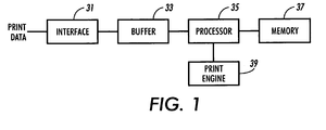
- FIG. 1 is a schematic block diagram of an embodiment of a printing apparatus that includes an interface 31 that receives print data, for example from a host computer, and stores the print data in a buffer memory 33.
- a processor 35 is configured to process the print data to produce bit mapped raster data that is stored in a memory 37.
- a print engine 39 prints an image pursuant to the bit map raster data generated by the processor 35.
- the print engine 39 can be an electrophotographic print engine or an ink jet print engine, for example.
- Printing is accomplished by selectively printing, depositing, applying or otherwise forming markings such as dots on a receiver surface or substrate that can be a print output medium such as paper or a transfer surface such as a transfer drum. If a transfer surface is used, the image formed or printed on the transfer surface is appropriately transferred to a print output medium such as paper.
- the markings can be formed at locations of a grid pattern that can be called a pixel array wherein each location that is capable of receiving at least one marking is called a pixel or pixel location.
- the data produced by the processor that defines what marking(s), if any, are to be applied to pixel locations on a pixel by pixel basis can be called pixel data.
- the pixel data can comprise a plurality of bit-maps, one bit-map for each primary color plane (e.g., cyan, magenta, yellow, black).
- a bit-map can be considered a bilevel pixel data array.
- FIG. 2 is a schematic illustration of an embodiment of an uncompressed half-toned bit-map 20 that is organized or partitioned into multi-pixel compression cells or sub-groups C(0, 0) through C(4, 4), and an embodiment of an associated half-tone threshold value array, whereby each pixel of the bit-map has an associated half-tone threshold value.
- Each square of the bit-map represents a pixel data bit or pixel, for example for a given color plane. Illustrating a half-toned bit-map in a grid pattern can aid in understanding that each bit is data for a particular location in a pixel array for a particular color.
- the number in a square is the half-tone threshold value associated with the pixel or bit represented by that square.
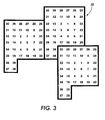
- the half-tone threshold value array comprises a tessellation of a 41-level half-tone cell shown in FIG. 3. In actual implementations, the half-tone cells employed can be larger or smaller.
- the contents of the half-toned bit-map would comprise for example the result of half-toning multi-bit pixel data (e.g., continuous tone, gray-scale, luminance, darkness, intensity or multi-level pixel data) to bitmapped raster data that contains one bit per pixel in accordance with the particular half-tone threshold values.
- multi-bit pixel data e.g., continuous tone, gray-scale, luminance, darkness, intensity or multi-level pixel data
- bitmapped raster data that contains one bit per pixel in accordance with the particular half-tone threshold values.
- FIG. 4 is a schematic illustration of an embodiment of a compressed bit-map that is based on marked pixel count compression of the half-toned bit-map of FIG. 2, and includes an array of marked pixel counts M(0, 0) through M(4, 4), wherein each pixel count is set to the number of pixels that are on in the corresponding compression cell of the half-toned bit-map of FIG. 2.
- each marked pixel count is employed to populate a decompressed cell of a decompressed bit-map.
- FIG. 5 is a schematic illustration of an embodiment of a decompressed bit-map that is organized or partitioned into a plurality of decompressed cells or sub-groups DC(0, 0) through DC(4, 4) that are respectively associated with respective compression cells C(0, 0) through C(4, 4) of the source or original bit-map depicted in FIG. 2.
- the decompressed cells can be substantially identical in size (i.e., number of pixels), shape (i.e., number of rows and number of columns), and location (i.e., position in a bit-map) to respectively associated compression cells CO-CN in the original uncompressed bit-map depicted in FIG. 2.
- FIG. 5 further illustrates for each decompressed cell an embodiment of an associated decompression cell fill order value pattern that is based on the half-tone threshold values for corresponding pixels of a corresponding compression cell in FIG. 2.
- each pixel of a decompressed cell more particularly has an associated fill-order value or sequence number that corresponds to the relative order of the corresponding threshold value in the corresponding compression cell, such that each pixel of a decompressed cell has an associated fill-order value between 0 and N-1, wherein N is number of pixels in each of the compression and decompressed cells.
- the fill order values associated with a decompressed cell correspond to the relative ordering of the threshold values in the corresponding compression cell. For the particular example of a 4 pixel by 4 pixel cell, N is 16.
- FIG. 6 is a schematic flow diagram of a procedure for defining the decompression fill order values for the pixels of the decompressed cells.
- a half-toned bit-map is partitioned into a plurality of N-pixel compression cells, wherein N is greater than 1.
- the fill order values for each decompressed cell are set to the relative ordering of the half-tone threshold values for the corresponding compression cell, such that the fill order values are between 0 and N-1.
- each decompressed cell has an associated fill order pattern that is based solely on the half-tone threshold values for the corresponding compression cell, and a set of decompressed bit patterns, one for each possible marked pixel count, can be computed for each decompressed cell.
- FIG. 7 is a schematic illustration of embodiments of decompression patterns for the different marked bit counts that would be employed for the upper right hand decompressed cell DC(0, 4) of the decompressed bit-map of FIG. 5.
- the decompressed bit map would be written or populated in accordance with the respective decompression patterns as selected or pointed to by the marked pixel counts.
- the fill order pattern for a decompressed cell is defined by the relative ordering of the half-tone threshold values of the pixels of the corresponding compression cell.
- FIG. 8 is a schematic flow diagram of a procedure for compressing and decompressing an uncompressed half-toned bit-map that is based on a predetermined half-tone threshold value array.
- a half-toned bit-map is partitioned into a plurality of N-pixel compression cells.
- a marked pixel count is determined for each compression cell to produce a compressed bit-map that comprises an array of marked pixel counts. More generally, a count of the number of pixels in a predetermined state (e.g., on or off) can be employed.
- the pixels of a decompressed bit-map are written based on the marked pixel counts and decompression cell fill order values that are based on the half-tone threshold values associated with the corresponding compression cells.
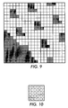
- FIG. 9 is an embodiment of an uncompressed half-toned bit-map that contains pixel values in the form of shaded (pixel on) and non-shaded (pixel off) squares, and which can be marked pixel count compressed to form a compressed bit-map of FIG. 10.
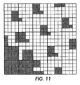
- the compressed bit-map of FIG. 10 can be decompressed in accordance with the foregoing to arrive at a decompressed bit-map shown in FIG. 11.
Landscapes
- Engineering & Computer Science (AREA)
- Multimedia (AREA)
- Signal Processing (AREA)
- Color, Gradation (AREA)
- Compression Of Band Width Or Redundancy In Fax (AREA)
Abstract
Description
- Raster type printers, which have been implemented with various print engines such as electrophotographic print engines and ink jet print engines, sometimes employ lossy bit-map compression and decompression so that all pages will print. Lossy compression/decompression can result in unwanted artifacts, and it can be difficult to reduce artifacts when lossy compression/decompression is employed.
Therefore, it is an object to provide a technique that permits to avoid or at least reduce the problem identified above.
According to various aspects the object is solved by methods as defined inclaims - In other aspects the invention relates to a data structure comprising:
- an array of decompression fill order values based on half-tone threshold values for corresponding pixels of a compression cell of a half-toned bit map.
-
- In a further embodiment the fill order values are a sequence that corresponds to the relative ordering of the half-tone threshold values.
- According to a further aspect of the invention a printing apparatus comprises:
- a memory for storing a compressed half-toned bit-map;
- a processor for decompressing the compressed half-toned bit-map into a decompressed bit-map that includes a plurality of decompressed cells, wherein each decompressed cell has an associated fill-order pattern that is based on half-tone threshold values for a corresponding compression cell of an uncompressed half-toned bit-map on which the compressed half-toned bit map is based.
-
- In a further embodiment the fill order pattern comprises a sequence that corresponds to the relative ordering of the half-tone threshold values of the uncompressed half-toned bit-map.
-
- FIG. 1 is a schematic block diagram of an embodiment of a raster type printing system.
- FIG. 2 is a schematic illustration of an embodiment of an uncompressed half-toned bit-map that is partitioned into a plurality of multi-pixel compression cells, and an embodiment of an associated half-tone threshold value array.
- FIG. 3 is a schematic illustration of an embodiment of a half-tone cell that was employed to form the half-tone threshold value array illustrated in FIG. 2.
- FIG. 4 is a schematic illustration of an embodiment of a compressed bit-map that is the result of a marked pixel count compression of the bit-map of FIG. 2.
- FIG. 5 is a schematic illustration of an embodiment of a decompressed bit-map that is partitioned into a plurality of multi-pixel decompressed cells, and an embodiment of fill order value arrays respectively associated with the decompressed cells.
- FIG. 6 is a schematic flow diagram of an embodiment of a procedure for determining fill order values for an array of decompressed cells.
- FIG. 7 is a schematic illustration of embodiments of decompressed patterns for the different marked bit counts that would be employed for the upper right hand decompressed cell of the decompressed bit-map of FIG. 5.
- FIG. 8 is a schematic flow diagram of an embodiment of a procedure for compressing a bit-map to a compressed bit-map and decompressing the compressed bit-map to a decompressed bit-map.
- FIG. 9 is a schematic illustration of an embodiment of a bit-map that includes pixel data or bit values.
- FIG. 10 is a schematic illustration of an embodiment of a compressed bit-map that can result from compression of the bit-map of FIG. 8.
- FIG. 11 is a schematic illustration of an embodiment of a decompressed bit-map that can result from de-compression of the compressed bit-map of FIG. 9.
-
- FIG. 1 is a schematic block diagram of an embodiment of a printing apparatus that includes an
interface 31 that receives print data, for example from a host computer, and stores the print data in abuffer memory 33. Aprocessor 35 is configured to process the print data to produce bit mapped raster data that is stored in amemory 37. Aprint engine 39 prints an image pursuant to the bit map raster data generated by theprocessor 35. Theprint engine 39 can be an electrophotographic print engine or an ink jet print engine, for example. - Printing is accomplished by selectively printing, depositing, applying or otherwise forming markings such as dots on a receiver surface or substrate that can be a print output medium such as paper or a transfer surface such as a transfer drum. If a transfer surface is used, the image formed or printed on the transfer surface is appropriately transferred to a print output medium such as paper. In raster type printing, the markings can be formed at locations of a grid pattern that can be called a pixel array wherein each location that is capable of receiving at least one marking is called a pixel or pixel location. The data produced by the processor that defines what marking(s), if any, are to be applied to pixel locations on a pixel by pixel basis can be called pixel data. Commonly, the pixel data can comprise a plurality of bit-maps, one bit-map for each primary color plane (e.g., cyan, magenta, yellow, black). A bit-map can be considered a bilevel pixel data array.
- FIG. 2 is a schematic illustration of an embodiment of an uncompressed half-toned bit-
map 20 that is organized or partitioned into multi-pixel compression cells or sub-groups C(0, 0) through C(4, 4), and an embodiment of an associated half-tone threshold value array, whereby each pixel of the bit-map has an associated half-tone threshold value. Each square of the bit-map represents a pixel data bit or pixel, for example for a given color plane. Illustrating a half-toned bit-map in a grid pattern can aid in understanding that each bit is data for a particular location in a pixel array for a particular color. The number in a square is the half-tone threshold value associated with the pixel or bit represented by that square. For ease of illustration, the half-tone threshold value array comprises a tessellation of a 41-level half-tone cell shown in FIG. 3. In actual implementations, the half-tone cells employed can be larger or smaller. - The contents of the half-toned bit-map would comprise for example the result of half-toning multi-bit pixel data (e.g., continuous tone, gray-scale, luminance, darkness, intensity or multi-level pixel data) to bitmapped raster data that contains one bit per pixel in accordance with the particular half-tone threshold values. It should be appreciated that the contents of the half-toned bit-map can be generated one band or portion at a time and then compressed for convenient storage in memory. The compressed bit-map is then decompressed to a decompressed bit-map so that it can be printed.
- FIG. 4 is a schematic illustration of an embodiment of a compressed bit-map that is based on marked pixel count compression of the half-toned bit-map of FIG. 2, and includes an array of marked pixel counts M(0, 0) through M(4, 4), wherein each pixel count is set to the number of pixels that are on in the corresponding compression cell of the half-toned bit-map of FIG. 2. In use, each marked pixel count is employed to populate a decompressed cell of a decompressed bit-map.
- FIG. 5 is a schematic illustration of an embodiment of a decompressed bit-map that is organized or partitioned into a plurality of decompressed cells or sub-groups DC(0, 0) through DC(4, 4) that are respectively associated with respective compression cells C(0, 0) through C(4, 4) of the source or original bit-map depicted in FIG. 2. The decompressed cells can be substantially identical in size (i.e., number of pixels), shape (i.e., number of rows and number of columns), and location (i.e., position in a bit-map) to respectively associated compression cells CO-CN in the original uncompressed bit-map depicted in FIG. 2. FIG. 5 further illustrates for each decompressed cell an embodiment of an associated decompression cell fill order value pattern that is based on the half-tone threshold values for corresponding pixels of a corresponding compression cell in FIG. 2.
- For example, each pixel of a decompressed cell more particularly has an associated fill-order value or sequence number that corresponds to the relative order of the corresponding threshold value in the corresponding compression cell, such that each pixel of a decompressed cell has an associated fill-order value between 0 and N-1, wherein N is number of pixels in each of the compression and decompressed cells. In other words, the fill order values associated with a decompressed cell correspond to the relative ordering of the threshold values in the corresponding compression cell. For the particular example of a 4 pixel by 4 pixel cell, N is 16.
- FIG. 6 is a schematic flow diagram of a procedure for defining the decompression fill order values for the pixels of the decompressed cells.
- At 111 a half-toned bit-map is partitioned into a plurality of N-pixel compression cells, wherein N is greater than 1.
- At 11 the fill order values for each decompressed cell are set to the relative ordering of the half-tone threshold values for the corresponding compression cell, such that the fill order values are between 0 and N-1.
- In this manner, each decompressed cell has an associated fill order pattern that is based solely on the half-tone threshold values for the corresponding compression cell, and a set of decompressed bit patterns, one for each possible marked pixel count, can be computed for each decompressed cell. FIG. 7 is a schematic illustration of embodiments of decompression patterns for the different marked bit counts that would be employed for the upper right hand decompressed cell DC(0, 4) of the decompressed bit-map of FIG. 5. The decompressed bit map would be written or populated in accordance with the respective decompression patterns as selected or pointed to by the marked pixel counts. In other words, the fill order pattern for a decompressed cell is defined by the relative ordering of the half-tone threshold values of the pixels of the corresponding compression cell.
- FIG. 8 is a schematic flow diagram of a procedure for compressing and decompressing an uncompressed half-toned bit-map that is based on a predetermined half-tone threshold value array.
- At 211 a half-toned bit-map is partitioned into a plurality of N-pixel compression cells.
- At 213 a marked pixel count is determined for each compression cell to produce a compressed bit-map that comprises an array of marked pixel counts. More generally, a count of the number of pixels in a predetermined state (e.g., on or off) can be employed.
- At 215 the pixels of a decompressed bit-map are written based on the marked pixel counts and decompression cell fill order values that are based on the half-tone threshold values associated with the corresponding compression cells.
- FIG. 9 is an embodiment of an uncompressed half-toned bit-map that contains pixel values in the form of shaded (pixel on) and non-shaded (pixel off) squares, and which can be marked pixel count compressed to form a compressed bit-map of FIG. 10. The compressed bit-map of FIG. 10 can be decompressed in accordance with the foregoing to arrive at a decompressed bit-map shown in FIG. 11.
Claims (10)
- A method of processing a half-toned bit-map, comprising:partitioning the half-toned bit-map into a plurality of N-pixel compression cells;storing for each compression cell a respective pixel count of pixels that are in a predetermined state in each compression cell;respectively associating a plurality of N-pixel decompressed cells of a decompressed bit map with the plurality of compression cells, each decompressed cell having an associated fill order pattern of fill order values that are based on half-tone threshold values for corresponding pixels of the associated compression cell, wherein the decompression fill order values are between 0 and N-1; andwriting pixels of the decompressed bit-map in accordance with the pixel counts and the decompression cell fill order patterns.
- The method of claim 1 wherein respectively associating comprises respectively associating the plurality of compression cells with a plurality of N-bit decompressed cells of a decompressed bit map, each decompressed cell having an associated fill order pattern of fill order values that comprise a sequence that corresponds to a relative ordering of half-tone threshold values for corresponding pixels of the associated compression cell, wherein the decompression fill order values are between 0 and N-1.
- A method for decompressing a compressed bit map containing a plurality of pixel counts respectively associated with a plurality of compression cells of an uncompressed half-toned bit-map, comprising:respectively associating a plurality of decompressed cells of a decompressed bit-map with the plurality of compression cells, each decompressed cell having a decompression fill order pattern of fill order values that are based on half-tone threshold values of the corresponding pixels of the associated compression cell; andwriting data in the decompressed bit-map in accordance with the pixel counts and the decompression cell fill order pattern.
- The method of claim 3 wherein the decompression fill order pattern comprises a sequence that corresponds to the relative order of the half-tone threshold values of the corresponding pixels of the associated compression cell.
- A method for decompressing a compressed bit-map containing a plurality of marked pixel counts, comprising:for each pixel count writing a decompressed cell of a decompressed bit-map in accordance with the marked pixel count and a fill order pattern based on half-tone threshold values of an uncompressed half-toned bit map compression cell that was used to determine the marked pixel count.
- The method of claim 5 wherein the fill order pattern comprises a sequence that corresponds to the relative order of the half-tone threshold values of the half-toned bit-map compression cell that was used to determine the pixel count.
- A method of writing data in a bit-map, comprising:partitioning a bit-map into a plurality of sub-groups of pixels;associating with each sub-group a respective pixel count;associating with each sub-group a fill order pattern based on half-tone threshold values of a corresponding sub-group of an uncompressed half-toned bit-map;for each sub-group, assigning pixel bit values in accordance with an associated pixel count and an associated fill order pattern.
- The method of claim 5 wherein the fill order pattern comprises a sequence that corresponds to the relative ordering of the half-tone threshold values of the corresponding sub-group of the uncompressed half-toned bit-map.
- A method for writing a de-compressed bit-map, comprising:writing bits of a de-compressed bit-map in accordance with marked pixel counts of a compressed bit map and a fill order pattern based on half-tone threshold values of an uncompressed half-toned bit map.
- The method of claim 9 wherein the fill order pattern comprises a sequence that corresponds to the relative ordering of the half-tone threshold values of the uncompressed half-toned bit-map.
Applications Claiming Priority (2)
| Application Number | Priority Date | Filing Date | Title |
|---|---|---|---|
| US274470 | 2002-10-17 | ||
| US10/274,470 US8077332B2 (en) | 2002-10-17 | 2002-10-17 | Bit-map decompression |
Publications (2)
| Publication Number | Publication Date |
|---|---|
| EP1411713A1 true EP1411713A1 (en) | 2004-04-21 |
| EP1411713B1 EP1411713B1 (en) | 2006-03-29 |
Family
ID=32042967
Family Applications (1)
| Application Number | Title | Priority Date | Filing Date |
|---|---|---|---|
| EP03023596A Expired - Lifetime EP1411713B1 (en) | 2002-10-17 | 2003-10-16 | Bit-map decompression |
Country Status (4)
| Country | Link |
|---|---|
| US (1) | US8077332B2 (en) |
| EP (1) | EP1411713B1 (en) |
| JP (1) | JP2004140826A (en) |
| DE (1) | DE60304268T2 (en) |
Cited By (1)
| Publication number | Priority date | Publication date | Assignee | Title |
|---|---|---|---|---|
| CN113619119A (en) * | 2020-08-14 | 2021-11-09 | 珠海赛纳三维科技有限公司 | Printing system, method, storage medium and three-dimensional model of three-dimensional object |
Families Citing this family (9)
| Publication number | Priority date | Publication date | Assignee | Title |
|---|---|---|---|---|
| US7685104B2 (en) * | 2004-01-08 | 2010-03-23 | International Business Machines Corporation | Dynamic bitmap processing, identification and reusability |
| WO2005112426A1 (en) * | 2004-05-19 | 2005-11-24 | Seiko Epson Corporation | Dot data processing device, image output system, and method thereof |
| JP4506652B2 (en) * | 2005-11-18 | 2010-07-21 | セイコーエプソン株式会社 | High quality halftone processing |
| JP4534963B2 (en) * | 2005-11-18 | 2010-09-01 | セイコーエプソン株式会社 | Image forming method, image forming apparatus, image forming system, printing method, printed matter generating method, and computer program for controlling image forming apparatus |
| JP4534964B2 (en) * | 2005-11-18 | 2010-09-01 | セイコーエプソン株式会社 | Image forming method, image forming apparatus, image forming system, printed matter generation method, and computer program for controlling image forming apparatus |
| JP2007310577A (en) * | 2006-05-17 | 2007-11-29 | Toshiba Corp | Drawing data extraction apparatus, method, and program |
| JP4507265B2 (en) * | 2008-06-30 | 2010-07-21 | ルネサスエレクトロニクス株式会社 | Image processing circuit, and display panel driver and display device having the same |
| US9654667B1 (en) | 2016-05-06 | 2017-05-16 | Xerox Corporation | System and method for stochastic vector halftoning of contone data in a printer having variable printing parameters |
| US9641726B1 (en) | 2016-05-06 | 2017-05-02 | Xerox Corporation | Multi-ink vector halftoning using multi-bit vector halftoning methods |
Citations (5)
| Publication number | Priority date | Publication date | Assignee | Title |
|---|---|---|---|---|
| US4760460A (en) * | 1984-01-20 | 1988-07-26 | Ricoh Company, Ltd. | Halftone image transmission method |
| US5216753A (en) * | 1990-03-29 | 1993-06-01 | Eastman Kodak Company | Halftone compression with sharpness preservation |
| US5359430A (en) * | 1992-05-15 | 1994-10-25 | Microsoft Corporation | Block-halftoning method and system with compressed error image |
| EP0683599A1 (en) * | 1994-05-16 | 1995-11-22 | International Business Machines Corporation | Image processing apparatus and method |
| US5917952A (en) * | 1995-09-20 | 1999-06-29 | Hewlett-Packard Company | Compression of randomly dithered bi-level images |
Family Cites Families (2)
| Publication number | Priority date | Publication date | Assignee | Title |
|---|---|---|---|---|
| US5444551A (en) * | 1992-07-22 | 1995-08-22 | Eastman Kodak Company | Process for specifying mean-preserving mutli-level halftone matrices with varying amounts of modulation |
| US5777757A (en) * | 1995-06-05 | 1998-07-07 | Apple Computer, Inc. | Method and system for halftoning |
-
2002
- 2002-10-17 US US10/274,470 patent/US8077332B2/en not_active Expired - Fee Related
-
2003
- 2003-10-10 JP JP2003351531A patent/JP2004140826A/en active Pending
- 2003-10-16 DE DE60304268T patent/DE60304268T2/en not_active Expired - Lifetime
- 2003-10-16 EP EP03023596A patent/EP1411713B1/en not_active Expired - Lifetime
Patent Citations (5)
| Publication number | Priority date | Publication date | Assignee | Title |
|---|---|---|---|---|
| US4760460A (en) * | 1984-01-20 | 1988-07-26 | Ricoh Company, Ltd. | Halftone image transmission method |
| US5216753A (en) * | 1990-03-29 | 1993-06-01 | Eastman Kodak Company | Halftone compression with sharpness preservation |
| US5359430A (en) * | 1992-05-15 | 1994-10-25 | Microsoft Corporation | Block-halftoning method and system with compressed error image |
| EP0683599A1 (en) * | 1994-05-16 | 1995-11-22 | International Business Machines Corporation | Image processing apparatus and method |
| US5917952A (en) * | 1995-09-20 | 1999-06-29 | Hewlett-Packard Company | Compression of randomly dithered bi-level images |
Non-Patent Citations (1)
| Title |
|---|
| MARTINS B ET AL: "HALFTONE CODING WITH JBIG2", JOURNAL OF ELECTRONIC IMAGING, SPIE + IS&T, US, vol. 9, no. 1, January 2000 (2000-01-01), pages 52 - 60, XP000902785, ISSN: 1017-9909 * |
Cited By (2)
| Publication number | Priority date | Publication date | Assignee | Title |
|---|---|---|---|---|
| CN113619119A (en) * | 2020-08-14 | 2021-11-09 | 珠海赛纳三维科技有限公司 | Printing system, method, storage medium and three-dimensional model of three-dimensional object |
| CN113619119B (en) * | 2020-08-14 | 2023-10-24 | 珠海赛纳三维科技有限公司 | Printing system, printing method, storage medium and three-dimensional model of three-dimensional object |
Also Published As
| Publication number | Publication date |
|---|---|
| US20040075706A1 (en) | 2004-04-22 |
| DE60304268D1 (en) | 2006-05-18 |
| EP1411713B1 (en) | 2006-03-29 |
| US8077332B2 (en) | 2011-12-13 |
| DE60304268T2 (en) | 2006-08-31 |
| JP2004140826A (en) | 2004-05-13 |
Similar Documents
| Publication | Publication Date | Title |
|---|---|---|
| JP4100782B2 (en) | Error diffusion value processing method | |
| US5949964A (en) | Method and apparatus for halftoning of images in a printer | |
| US8098405B2 (en) | Laser print apparatus with dual halftones | |
| US8077332B2 (en) | Bit-map decompression | |
| US7667711B2 (en) | Image processing system, a method thereof, and a recording medium thereof | |
| US7145693B2 (en) | Image processing apparatus and method | |
| JP2001069358A (en) | Image processing apparatus and method, and storage medium | |
| JPH07322074A (en) | Equipment and method for data processing to process 2 level image file that a dither ring happened | |
| JP3045008B2 (en) | Halftone image compression method | |
| US5761347A (en) | Method and system for halftoning by tiling subsets of a threshold array over portions of an image | |
| US20050052468A1 (en) | Method of detecting half-toned uniform areas in bit-map | |
| US6389167B1 (en) | Multi-level pixel density reduction for printers | |
| JP3093290B2 (en) | Image processing device | |
| JP3743471B2 (en) | Printing system, printing apparatus and printing control apparatus | |
| JP3192113B2 (en) | Encoding device | |
| US6871928B1 (en) | Selective enhancement of black | |
| US20020060812A1 (en) | Image processing method and image processing apparatus | |
| JP3185435B2 (en) | Image forming device | |
| JPH05252385A (en) | Image processor | |
| JP2020185686A (en) | Image processing device. | |
| JP2006067294A (en) | Image processing method and image processing apparatus | |
| JP2000299785A (en) | Data converter | |
| US20110051198A1 (en) | System and method for inverse halftoning | |
| JPH05221031A (en) | Image forming device | |
| JPH068533A (en) | Image forming device |
Legal Events
| Date | Code | Title | Description |
|---|---|---|---|
| PUAI | Public reference made under article 153(3) epc to a published international application that has entered the european phase |
Free format text: ORIGINAL CODE: 0009012 |
|
| AK | Designated contracting states |
Kind code of ref document: A1 Designated state(s): AT BE BG CH CY CZ DE DK EE ES FI FR GB GR HU IE IT LI LU MC NL PT RO SE SI SK TR |
|
| AX | Request for extension of the european patent |
Extension state: AL LT LV MK |
|
| 17P | Request for examination filed |
Effective date: 20041021 |
|
| AKX | Designation fees paid |
Designated state(s): DE FR GB |
|
| 17Q | First examination report despatched |
Effective date: 20050118 |
|
| GRAP | Despatch of communication of intention to grant a patent |
Free format text: ORIGINAL CODE: EPIDOSNIGR1 |
|
| GRAS | Grant fee paid |
Free format text: ORIGINAL CODE: EPIDOSNIGR3 |
|
| GRAA | (expected) grant |
Free format text: ORIGINAL CODE: 0009210 |
|
| AK | Designated contracting states |
Kind code of ref document: B1 Designated state(s): DE FR GB |
|
| REG | Reference to a national code |
Ref country code: GB Ref legal event code: FG4D |
|
| REF | Corresponds to: |
Ref document number: 60304268 Country of ref document: DE Date of ref document: 20060518 Kind code of ref document: P |
|
| ET | Fr: translation filed | ||
| PLBE | No opposition filed within time limit |
Free format text: ORIGINAL CODE: 0009261 |
|
| STAA | Information on the status of an ep patent application or granted ep patent |
Free format text: STATUS: NO OPPOSITION FILED WITHIN TIME LIMIT |
|
| 26N | No opposition filed |
Effective date: 20070102 |
|
| PGFP | Annual fee paid to national office [announced via postgrant information from national office to epo] |
Ref country code: GB Payment date: 20130923 Year of fee payment: 11 |
|
| PGFP | Annual fee paid to national office [announced via postgrant information from national office to epo] |
Ref country code: DE Payment date: 20130920 Year of fee payment: 11 Ref country code: FR Payment date: 20131028 Year of fee payment: 11 |
|
| REG | Reference to a national code |
Ref country code: DE Ref legal event code: R119 Ref document number: 60304268 Country of ref document: DE |
|
| GBPC | Gb: european patent ceased through non-payment of renewal fee |
Effective date: 20141016 |
|
| PG25 | Lapsed in a contracting state [announced via postgrant information from national office to epo] |
Ref country code: GB Free format text: LAPSE BECAUSE OF NON-PAYMENT OF DUE FEES Effective date: 20141016 Ref country code: DE Free format text: LAPSE BECAUSE OF NON-PAYMENT OF DUE FEES Effective date: 20150501 |
|
| REG | Reference to a national code |
Ref country code: FR Ref legal event code: ST Effective date: 20150630 |
|
| PG25 | Lapsed in a contracting state [announced via postgrant information from national office to epo] |
Ref country code: FR Free format text: LAPSE BECAUSE OF NON-PAYMENT OF DUE FEES Effective date: 20141031 |