EP1411672A2 - Method and wireless device for handling a triggered reset of a radio link control entity in a wireless communications system - Google Patents
Method and wireless device for handling a triggered reset of a radio link control entity in a wireless communications system Download PDFInfo
- Publication number
- EP1411672A2 EP1411672A2 EP03022633A EP03022633A EP1411672A2 EP 1411672 A2 EP1411672 A2 EP 1411672A2 EP 03022633 A EP03022633 A EP 03022633A EP 03022633 A EP03022633 A EP 03022633A EP 1411672 A2 EP1411672 A2 EP 1411672A2
- Authority
- EP
- European Patent Office
- Prior art keywords
- rlc
- reset
- timer
- rlc entity
- entity
- Prior art date
- Legal status (The legal status is an assumption and is not a legal conclusion. Google has not performed a legal analysis and makes no representation as to the accuracy of the status listed.)
- Withdrawn
Links
Images



Classifications
-
- H—ELECTRICITY
- H04—ELECTRIC COMMUNICATION TECHNIQUE
- H04W—WIRELESS COMMUNICATION NETWORKS
- H04W80/00—Wireless network protocols or protocol adaptations to wireless operation
- H04W80/02—Data link layer protocols
-
- H—ELECTRICITY
- H04—ELECTRIC COMMUNICATION TECHNIQUE
- H04W—WIRELESS COMMUNICATION NETWORKS
- H04W88/00—Devices specially adapted for wireless communication networks, e.g. terminals, base stations or access point devices
- H04W88/02—Terminal devices
Definitions
- the present invention relates to a method for handling a triggered reset of a radio link control (RLC) entity, and more specifically, to a method for handling a triggered reset of a stopped RLC entity in a wireless communications system.
- RLC radio link control
- Fig. 1 is a simplified block diagram of the prior art communications model.
- a first station 10 is in wireless communications with one or more second stations 20.
- the first station 10 is comprised of a radio resource control (RRC) 12, a radio link control (RLC) entity 14, and lower layers 16 which are below the RLC 14.
- the RRC 12 can deliver messages to the RLC 14 through service data units (SDUs) 13.
- SDUs 13 may be of any size, and hold data that the RRC 12 wishes delivered to the second station 20.
- the RLC 14 composes the SDUs 13 into one or more protocol data units (PDUs) 15. Each PDU 15 of the RLC 14 is delivered to the lower layers 16.
- the lower layers 16 include the physical layer, which is in charge of transmitting data to the second station 20.
- the second station 20 shown has exactly the same basic structure as the first station 10.
- the second station 20 also includes an RRC 22, an RLC 24, and lower layers 26.
- the second station 20 uses the RRC 22 to transmit SDUs 23 to the RLC 24, and uses the RLC 24 to transmit PDUs 25 to the lower layers 26.
- the data transmitted by the first station 10 is received by lower layers 26 of the second station 20 and reconstructed into one or more PDUs 25, which are passed up to the RLC 24.
- the RLC 24 receives the PDUs 25 and from them assembles one or more SDUs 23, which are then passed up to the RRC 22.
- the RRC 22, converts the SDUs 23 back into messages which should be identical to the original messages that was generated by the first station 10.
- SDU and PDU have broad meanings.
- SDU is used to indicate SDUs passed from the RRC to the RLC
- PDU should be understood as PDUs passed from the RLC to lower layers.
- Resetting and stopping the RLC 14 is defined by the 3 rd Generation Partnership Project (3GPP) specification 3GPP TS 25 .322 V3 .10 . 0 "RLC Protocol Specification", which is included herein by reference.
- 3GPP 3 rd Generation Partnership Project
- RLC stop function and RLC continue function for both acknowledged mode and unacknowledged mode, RLC timers are not affected when the RLC entity 14 is stopped.
- the RRC 12 or other upper layers may be indicated to stop the RLC 14 in order to prevent overloading of the second station 20.
- triggered polling functions and status transmissions are delayed until the RLC entity 14 is continued.
- the current 3GPP specification does not specify how to handle a triggered reset while the RLC entity is stopped.
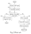
- Fig.2 is a flowchart illustrating resetting a stopped RLC entity according to the prior art. This problem occurs when a RESET PDU is sent by the RLC entity 14, and the RLC 14 is stopped before the RLC 14 receives a RESET ACK PDU.
- deadlock occurs because the Timer_RST timer expires while the RLC 14 is stopped, and because the RLC 14 is not allowed to submit any RLC PDUs to the lower layers 16 or to receive any RLC PDUs from the lower layers 16. Therefore, after the RLC 14 is continued, there is no way to reset the RLC 14, and deadlock occurs.
- a method for handling a triggered reset of a radio link control (RLC) entity in a wireless communications system includes the RLC entity initiating an RLC reset procedure by causing a reset protocol data unit (RESET PDU) to be transmitted and starting a Timer_RST timer, an upper layer stopping the RLC entity prior to the RLC entity receiving a RESET ACK PDU in response to the reset procedure, delaying a triggered reset of the RLC entity caused by expiration of the Timer_RST timer until after the RLC entity has been continued by the upper layer, and the RLC entity processing the triggered reset after the RLC entity is continued by the upper layer.
- RESET PDU reset protocol data unit
- Fig.3 is a flowchart illustrating resetting a stopped RLC entity according to a first embodiment of the present invention.
- the first embodiment of the present invention prevents deadlock of the RLC entity 14 by delaying a triggered reset until after the RLC entity 14 is continued.
- the flowchart in Fig.3 states that if the Timer_RST timer expired when the RLC 14 was stopped, a triggered reset of the RLC 14 caused by the expiration of the timer is delayed until after the RLC 14 is continued. This means that even though the Timer_RST timer expires when the RLC 14 is stopped and could not generate a RESET PDU, the present invention method allows the RLC 14 to wait until the RLC 14 is continued before generating a RESET PDU. In this way, the RLC 14 is properly reset, and deadlock does not occur.
- Fig.4 is a flowchart illustrating resetting a stopped RLC entity according to a second embodiment of the present invention.
- the second embodiment of the present invention prevents deadlock of the RLC entity 14 by restarting the Timer_RST timer if the timer expires while the RLC 14 is stopped by an upper layer.
- the flowchart in Fig.4 states that if the Timer_RST timer expired when the RLC 14 was stopped, the Timer_RST timer is restarted so as to wait until the RLC 14 is continued before generating a RESET PDU. In this way, the RLC 14 is properly reset, and deadlock does not occur.
- Fig.5 is a flowchart illustrating resetting a stopped RLC entity according to a third embodiment of the present invention.
- the third embodiment of the present invention prevents deadlock of the RLC entity 14 by enabling the RLC entity 14 to receive RESET ACK PDUs, and enabling the RLC entity 14 to transmit RESET PDUs while the RLC entity 14 is stopped by an upper layer.
- the flowchart in Fig. 5 states that the RLC entity 14 is allowed to receive RESET ACK PDUs, and allowed to transmit RESET PDUs while the RLC entity 14 is stopped. Therefore, the RLC entity 14 can use the expiration of the Timer_RST timer to generate new RESET PDUs, and also receive RESET ACK PDUs from the second station 20 in order to reset the RLC entity 14 and avoid deadlock.
- the present invention provides three embodiments for resetting an RLC entity that has been stopped by an upper layer.
- the present invention method can delay a triggered reset until a stopped RLC entity has been continued, restart a Timer_RST timer that expires while the RLC entity is stopped, or allow transmission and reception of RESET PDUs or RESET ACK PDUs.
- using any of the methods specified in the three embodiments of the present invention will prevent the RLC entity from experiencing deadlock.
Landscapes
- Engineering & Computer Science (AREA)
- Computer Networks & Wireless Communication (AREA)
- Signal Processing (AREA)
- Mobile Radio Communication Systems (AREA)
- Communication Control (AREA)
Abstract
Description
- Step 100:
- The RLC 14 of the
first station 10 sends a RESET PDU to thesecond station 20; - Step 102 :
- A Timer_RST timer is started when the
lower layers 16 indicate successful or unsuccessful transmission of the RESET PDU to theRLC 14. When the Timer_RST timer expires, another RESET PDU is sent from the RLC 14 to thesecond station 20; - Step 104:
- Determine if the RLC 14 has received a corresponding
RESET ACK PDU from the
second station 20. If so, go tostep 106. If not, go tostep 108; - Step 106:
- Since the RLC 24 of the
second station 20 has acknowledged the RESET PDU, the RLC 14 processes a triggered reset; - Step 108:
- The RLC 14 is stopped before receiving a RESET ACK
PDU from the
second station 20. Because the RLC 14 is stopped, the RLC 14 is not allowed to submit any RLC PDUs to thelower layers 16 or to receive any RLC PDUs from thelower layers 16; - Step 110:
- The Timer_RST timer expires. However, since the RLC 14 is stopped, the RLC 14 cannot submit a RESET PDU. Therefore, the Timer_RST timer is not restarted; and
- Step 112 :
- The RLC 14 is continued by the RRC 12 or other upper layers. Because the Timer_RST timer has expired and not been restarted, the RLC 14 cannot complete a reset procedure, and the RLC 14 experiences deadlock.
- Step 120:
- The
RLC 14 of thefirst station 10 sends a RESET PDU to thesecond station 20; - Step 122 :
- The Timer_RST timer is started when the
lower layers 16 indicate successful or unsuccessful transmission of the RESET PDU to theRLC 14. When the Timer_RST timer expires, another RESET PDU is sent from theRLC 14 to thesecond station 20; - Step 124:
- Determine if the
RLC 14 has received a corresponding RESET ACK PDU from thesecond station 20. If so, go to step 126. If not, go to step 128; - Step 126:
- Since the
RLC 24 of thesecond station 20 has acknowledged the RESET PDU, theRLC 14 processes a triggered reset; - Step 128:
- The
RLC 14 is stopped before receiving a RESET ACK PDU from thesecond station 20. Because theRLC 14 is stopped, theRLC 14 is not allowed to submit any RLC PDUs to thelower layers 16 or to receive any RLC PDUs from thelower layers 16; - Step 130:
- Determine if the Timer_RST timer has expired. If so, go to step 136. If not go to step 132;
- Step 132 :
- The
RLC 14 is continued by theRRC 12 or other upper layers; - Step 134:
- The Timer_RST timer expires. Go to step 138;
- Step 136:
- Since the Timer_RST timer expired when the
RLC 14 was stopped, a triggered reset of theRLC 14 caused by the expiration of the timer is delayed until after theRLC 14 is continued; - Step 137:
- The
RLC 14 is continued by theRRC 12 or other upper layers; - Step 138:
- Now that the
RLC 14 has been continued, theRLC 14 of thefirst station 10 sends a RESET PDU to thesecond station 20; and - Step 139:
- The Timer_RST timer is restarted when the
lower layers 16 indicate successful or unsuccessful transmission of the RESET PDU to theRLC 14; go to step 124.
- Step 140:
- The
RLC 14 of thefirst station 10 sends a RESET PDU to thesecond station 20; - Step 142 :
- The Timer_RST timer is started when the
lower layers 16 indicate successfulor unsuccessful transmission of the RESET PDU to theRLC 14. When the Timer_RST timer expires, another RESET PDU is sent from theRLC 14 to thesecond station 20; - Step 144:
- Determine if the
RLC 14 has received a corresponding RESET ACK PDU from thesecond station 20. If so, go to step 146. If not, go to step 148; - Step 146:
- Since the
RLC 24 of thesecond station 20 has acknowledged the RESET PDU, theRLC 14 processes a triggered reset; - Step 148:
- The
RLC 14 is stopped before receiving a RESET ACK PDU from thesecond station 20. Because theRLC 14 is stopped, theRLC 14 is not allowed to submit any RLC PDUs to thelower layers 16 or to receive any RLC PDUs from thelower layers 16; - Step 150:
- Determine if the Timer_RST timer has expired. If so, go to step 152. If not go to step 154;
- Step 152:
- Since the Timer_RST timer expired while the
RLC 14 was stopped, the Timer_RST timer is restarted; - Step 154:
- Determine if the RLC has been continued by upper layers. If so, go to step 156. If not go back to step 150;
- Step 156:
- The Timer_RST timer expires;
- Step 158:
- Now that the
RLC 14 has been continued, theRLC 14 of thefirst station 10 sends a RESET PDU to thesecond station 20; and - Step 159:
- The Timer_RST timer is restarted when the
lower layers 16 indicate successful or unsuccessful transmission of the RESET PDU to theRLC 14; go to step 144.
- Step 160:
- The
RLC 14 of thefirst station 10 sends a RESET PDU to thesecond station 20; - Step 162 :
- The Timer_RST timer is started when the
lower layers 16 indicate successful or unsuccessful transmission of the RESET PDU to theRLC 14. When the Timer_RST timer expires, another RESET PDU is sent from theRLC 14 to thesecond station 20; - Step 164:
- Determine if the
RLC 14 has received a corresponding RESET ACK PDU from thesecond station 20. If so, go to step 166. If not, go to step 168; - Step 166:
- Since the
RLC 24 of thesecond station 20 has acknowledged the RESET PDU, theRLC 14 processes a triggered reset; - Step 168:
- The
RLC 14 is stopped before receiving a RESET ACK PDU from thesecond station 20; - Step 170:
- Enable the
RLC entity 14 to receive RESET ACK PDUs, and enable theRLC entity 14 to transmit RESET PDUs while theRLC entity 14 is stopped; - Step 172:
- Determine if the Timer_RST timer has expired. If so, go to step 174. If not go to step 178;
- Step 174:
- Since the
RLC 14 is now allowed to send RESET PDUs, theRLC 14 sends a RESET PDU to thesecond station 20; - Step 176:
- The Timer_RST timer is restarted when the
lower layers 16 indicate successful or unsuccessful transmission of the RESET PDU to theRLC 14. Go back to step 172; - Step 178 :
- Determine if the
RLC 14 has received a corresponding RESET ACK PDU from thesecond station 20. If so, go to step 180. If not, go back to step 172; and - Step 180:
- Since the
RLC 24 of thesecond station 20 has acknowledged the RESET PDU, theRLC 14 processes a triggered reset.
Claims (6)
- A method for handling a triggered reset of a radio link control (RLC) entity in a wireless communications system, the method comprising:the RLC entity initiating an RLC reset procedure by causing a reset protocol data unit (RESET PDU) to be transmitted and starting a Timer_RST timer;an upper layer stopping the RLC entity prior to the RLC entity receiving a RESET ACK PDU in response to the reset procedure;delaying a triggered reset of the RLC entity caused by expiration of the Timer_RST timer until after the RLC entity has been continued by the upper layer; andthe RLC entity processing the triggered reset after the RLC entity is continued by the upper layer.
- A wireless device for implementing the method of claim 1.
- A method for resetting a radio link control (RLC) entity in a wireless communications system, the method comprising:the RLC entity initiating an RLC reset procedure by causing a reset protocol data unit (RESET PDU) to be transmitted and starting a Timer_RST timer;an upper layer stopping the RLC entity prior to the RLC entity receiving a RESET ACK PDU in response to the reset procedure; andthe RLC entity restarting the Timer_RST timer if the Timer_RST timer expires while the RLC entity is stopped by the upper layer.
- A wireless device for implementing the method of claim 3.
- A method for resetting a radio link control (RLC) entity in a wireless communicationssystem,the method comprising:the RLC entity initiating an RLC reset procedure by causing a reset protocol data unit (RESET PDU) to be transmitted;an upper layer stopping the RLC entity prior to the RLC entity receiving a RESET ACK PDU in response to the reset procedure; andenabling reception of RESET ACK PDUs while the RLC entity is stopped by the upper layer, and enabling transmission of RESET PDUs while the RLC entity is stopped by the upper layer.
- A wireless device for implementing the method of claim 5.
Applications Claiming Priority (2)
| Application Number | Priority Date | Filing Date | Title |
|---|---|---|---|
| US65435 | 2002-10-17 | ||
| US10/065,435 US20040076182A1 (en) | 2002-10-17 | 2002-10-17 | Method for handeling a triggered reset when an RLC is stopped in a wireless communications system |
Publications (2)
| Publication Number | Publication Date |
|---|---|
| EP1411672A2 true EP1411672A2 (en) | 2004-04-21 |
| EP1411672A3 EP1411672A3 (en) | 2006-09-06 |
Family
ID=32041319
Family Applications (1)
| Application Number | Title | Priority Date | Filing Date |
|---|---|---|---|
| EP03022633A Withdrawn EP1411672A3 (en) | 2002-10-17 | 2003-10-06 | Method and wireless device for handling a triggered reset of a radio link control entity in a wireless communications system |
Country Status (5)
| Country | Link |
|---|---|
| US (1) | US20040076182A1 (en) |
| EP (1) | EP1411672A3 (en) |
| JP (1) | JP2004140836A (en) |
| KR (1) | KR20040034398A (en) |
| TW (1) | TWI260884B (en) |
Cited By (1)
| Publication number | Priority date | Publication date | Assignee | Title |
|---|---|---|---|---|
| WO2008051126A1 (en) | 2006-10-27 | 2008-05-02 | Telefonaktiebolaget Lm Ericsson (Publ) | Method and arrangement for efficiently utilizing radio resources in a communication network |
Families Citing this family (41)
| Publication number | Priority date | Publication date | Assignee | Title |
|---|---|---|---|---|
| US7876740B2 (en) * | 2005-08-04 | 2011-01-25 | Motorola, Inc. | Method and system for synchronization of link layer windows |
| TWI398148B (en) * | 2005-09-21 | 2013-06-01 | Innovative Sonic Ltd | Method and apparatus for handling timers during re-establishing receiving sides in a wireless communications system |
| KR100905965B1 (en) | 2005-10-04 | 2009-07-06 | 엘지전자 주식회사 | Rlc re-establishment method in radio communication system |
| WO2008004725A1 (en) * | 2006-07-05 | 2008-01-10 | Lg Electronics Inc. | Optimized am rlc re-set mechanism |
| TW200731724A (en) * | 2006-02-06 | 2007-08-16 | Asustek Comp Inc | Method and apparatus of radio link control reset in a wireless communications system |
| TWI401907B (en) * | 2007-01-09 | 2013-07-11 | Innovative Sonic Ltd | Method and apparatus for handling reset in a wireless communications system |
| EP2429235B1 (en) | 2007-02-02 | 2018-07-25 | InterDigital Technology Corporation | Method and apparatus for enchancing RLC for flexible RLC PDU size |
| KR101341515B1 (en) * | 2007-06-18 | 2013-12-16 | 엘지전자 주식회사 | Method of updating repeatedly-transmitted information in wireless communicaiton system |
| KR101486352B1 (en) | 2007-06-18 | 2015-01-26 | 엘지전자 주식회사 | Uplink synchronization state control method in a terminal of a wireless communication system |
| WO2008156314A2 (en) | 2007-06-20 | 2008-12-24 | Lg Electronics Inc. | Effective system information reception method |
| KR101448644B1 (en) * | 2007-06-20 | 2014-10-13 | 엘지전자 주식회사 | Data transmission method in mobile communication system |
| KR101514841B1 (en) * | 2007-08-10 | 2015-04-23 | 엘지전자 주식회사 | Method for re-attempting a random access effectively |
| KR101495913B1 (en) | 2007-08-10 | 2015-02-25 | 엘지전자 주식회사 | Method for transmitting and receiving control data in mobile telecommunications system and transmitter and receiver of mobile telecommunications |
| KR101490253B1 (en) | 2007-08-10 | 2015-02-05 | 엘지전자 주식회사 | Method and apparatus for transmitting and receiving control information in a wireless communication system |
| WO2009022837A1 (en) * | 2007-08-10 | 2009-02-19 | Lg Electronics Inc. | A control method for uplink connection of idle terminal |
| KR101479341B1 (en) | 2007-08-10 | 2015-01-05 | 엘지전자 주식회사 | An efficient receiving method in a wireless communication system providing an MBMS service |
| US20110081868A1 (en) * | 2007-08-10 | 2011-04-07 | Yung Mi Kim | Method of reporting measurement result in wireless communication system |
| KR101422032B1 (en) * | 2007-08-10 | 2014-07-23 | 엘지전자 주식회사 | Method of setting a channel in a wireless communication system |
| KR20090016431A (en) | 2007-08-10 | 2009-02-13 | 엘지전자 주식회사 | How to Perform Channel Quality Reporting in Wireless Communication Systems |
| KR101422031B1 (en) * | 2007-08-10 | 2014-07-23 | 엘지전자 주식회사 | Random access method for broadcast and multicast service |
| US8594030B2 (en) * | 2007-08-10 | 2013-11-26 | Lg Electronics Inc. | Method for controlling HARQ operation in dynamic radio resource allocation |
| KR20090016412A (en) * | 2007-08-10 | 2009-02-13 | 엘지전자 주식회사 | Data communication method in wireless communication system |
| US8488523B2 (en) * | 2007-08-14 | 2013-07-16 | Lg Electronics Inc. | Method of transmitting and processing data block of specific protocol layer in wireless communication system |
| ES2419804T3 (en) | 2007-09-13 | 2013-08-21 | Lg Electronics Inc. | Procedure for assigning radio resources in a wireless communication system |
| KR100937432B1 (en) * | 2007-09-13 | 2010-01-18 | 엘지전자 주식회사 | Radio Resource Allocation Method in Wireless Communication System |
| KR101461970B1 (en) * | 2007-09-13 | 2014-11-14 | 엘지전자 주식회사 | A method of performing a polling process in a wireless communication system |
| KR101591824B1 (en) | 2007-09-18 | 2016-02-04 | 엘지전자 주식회사 | Method of performing polling procedure in a wireless communication system |
| KR101513033B1 (en) | 2007-09-18 | 2015-04-17 | 엘지전자 주식회사 | A method for qos guarantees in a multilayer structure |
| KR101435844B1 (en) * | 2007-09-18 | 2014-08-29 | 엘지전자 주식회사 | Method for transmitting data blocks in a wireless communication system |
| KR101396062B1 (en) * | 2007-09-18 | 2014-05-26 | 엘지전자 주식회사 | Effective data block transmission method using a header indicator |
| US8687565B2 (en) * | 2007-09-20 | 2014-04-01 | Lg Electronics Inc. | Method of effectively transmitting radio resource allocation request in mobile communication system |
| KR20090041323A (en) * | 2007-10-23 | 2009-04-28 | 엘지전자 주식회사 | Method for effectively transmitting identification information of terminal in data block configuration |
| KR101487557B1 (en) * | 2007-10-23 | 2015-01-29 | 엘지전자 주식회사 | Method of transmitting data of common control channel |
| EP2208294B1 (en) * | 2007-10-29 | 2019-07-31 | LG Electronics Inc. | Method of repairing a security failure |
| TW201511499A (en) | 2007-12-10 | 2015-03-16 | Interdigital Patent Holdings | Method and apparatus for triggering radio link control packet discard and radio link control re-establishment |
| WO2009096731A2 (en) | 2008-01-31 | 2009-08-06 | Lg Electronics Inc. | Method for signaling back-off information in random access |
| KR101594359B1 (en) | 2008-01-31 | 2016-02-16 | 엘지전자 주식회사 | Method of signaling back-off information in random access |
| US8270348B2 (en) | 2008-01-31 | 2012-09-18 | Lg Electronics Inc. | Method for sending status information in mobile telecommunications system and receiver of mobile telecommunications |
| US8958411B2 (en) * | 2008-03-17 | 2015-02-17 | Lg Electronics Inc. | Method of transmitting RLC data |
| KR101163275B1 (en) * | 2008-03-17 | 2012-07-05 | 엘지전자 주식회사 | Method for transmitting pdcp status report |
| CN101873193A (en) * | 2009-04-27 | 2010-10-27 | 中兴通讯股份有限公司 | Sending method of wireless link layer status packet |
Family Cites Families (3)
| Publication number | Priority date | Publication date | Assignee | Title |
|---|---|---|---|---|
| FI112753B (en) * | 2000-04-10 | 2003-12-31 | Nokia Corp | Method and arrangement for preserving synchronization in connection with the restoration of a communication connection |
| US20030007642A1 (en) * | 2001-07-05 | 2003-01-09 | Jiang Sam Shiaw-Shiang | Local suspend function and reset procedure in a wireless communications system |
| US6987981B2 (en) * | 2001-11-13 | 2006-01-17 | Asustek Computer Inc. | Robust RLC reset procedure in a wireless communication system |
-
2002
- 2002-10-17 US US10/065,435 patent/US20040076182A1/en not_active Abandoned
-
2003
- 2003-09-29 TW TW092126807A patent/TWI260884B/en not_active IP Right Cessation
- 2003-09-30 KR KR1020030067636A patent/KR20040034398A/en not_active Ceased
- 2003-10-06 EP EP03022633A patent/EP1411672A3/en not_active Withdrawn
- 2003-10-16 JP JP2003355805A patent/JP2004140836A/en active Pending
Cited By (5)
| Publication number | Priority date | Publication date | Assignee | Title |
|---|---|---|---|---|
| WO2008051126A1 (en) | 2006-10-27 | 2008-05-02 | Telefonaktiebolaget Lm Ericsson (Publ) | Method and arrangement for efficiently utilizing radio resources in a communication network |
| CN101529780A (en) * | 2006-10-27 | 2009-09-09 | 艾利森电话股份有限公司 | Method and apparatus for efficient utilization of radio resources in a communication network |
| US20100091721A1 (en) * | 2006-10-27 | 2010-04-15 | Telefonaktiebolaget Lm Ericsson (Publ) | Method and arrangement for efficiently utilizing radio resources in a communication network |
| EP2074732A4 (en) * | 2006-10-27 | 2012-05-09 | Ericsson Telefon Ab L M | Method and arrangement for efficiently utilizing radio resources in a communication network |
| US8699428B2 (en) | 2006-10-27 | 2014-04-15 | Telefonaktiebolaget L M Ericsson (Publ) | Method and arrangement for efficiently utilizing radio resources in a communication network |
Also Published As
| Publication number | Publication date |
|---|---|
| TW200415882A (en) | 2004-08-16 |
| KR20040034398A (en) | 2004-04-28 |
| JP2004140836A (en) | 2004-05-13 |
| EP1411672A3 (en) | 2006-09-06 |
| TWI260884B (en) | 2006-08-21 |
| US20040076182A1 (en) | 2004-04-22 |
Similar Documents
| Publication | Publication Date | Title |
|---|---|---|
| US20040076182A1 (en) | Method for handeling a triggered reset when an RLC is stopped in a wireless communications system | |
| US7554963B2 (en) | Method for handling data discard timer after an RLC reset or re-establishment in a wireless communications system | |
| US6904016B2 (en) | Processing unexpected transmission interruptions in a wireless communications system | |
| WO2025196528A1 (en) | Method, apparatus and computer program relating to providing feedback about data units | |
| WO2025196529A1 (en) | Method, apparatus and computer program relating to providing feedback about data units | |
| WO2025196527A1 (en) | Method, apparatus and computer program relating to providing feedback about data units | |
| US8081648B2 (en) | Method and apparatus for handling reset in a wireless communications system |
Legal Events
| Date | Code | Title | Description |
|---|---|---|---|
| PUAI | Public reference made under article 153(3) epc to a published international application that has entered the european phase |
Free format text: ORIGINAL CODE: 0009012 |
|
| AK | Designated contracting states |
Kind code of ref document: A2 Designated state(s): AT BE BG CH CY CZ DE DK EE ES FI FR GB GR HU IE IT LI LU MC NL PT RO SE SI SK TR |
|
| AX | Request for extension of the european patent |
Extension state: AL LT LV MK |
|
| PUAL | Search report despatched |
Free format text: ORIGINAL CODE: 0009013 |
|
| AK | Designated contracting states |
Kind code of ref document: A3 Designated state(s): AT BE BG CH CY CZ DE DK EE ES FI FR GB GR HU IE IT LI LU MC NL PT RO SE SI SK TR |
|
| AX | Request for extension of the european patent |
Extension state: AL LT LV MK |
|
| AKX | Designation fees paid | ||
| STAA | Information on the status of an ep patent application or granted ep patent |
Free format text: STATUS: THE APPLICATION IS DEEMED TO BE WITHDRAWN |
|
| 18D | Application deemed to be withdrawn |
Effective date: 20070605 |
|
| REG | Reference to a national code |
Ref country code: DE Ref legal event code: 8566 |