BACKGROUND OF THE INVENTION
1. Field of the Invention
The present invention relates to an optical ring network and, in particular to a
configuration of nodes provided in an optical ring network.
2. Description of the Related Art
Recent explosive growth in Internet traffic demands a higher bandwidth for all
networks including the backbone of an optical network, which is based on Wavelength
Division Multiplexing (WDM) scheme. The optical ring network is a network topology
that is attracting considerable attention due to its easy configuration, switching restoration,
lower initial costs, and so forth, and it has been already adopted in many countries in the
world.
In general, an optical ring network has to provide a full-mesh connectivity
between all nodes that constitute the network. Currently, the optical ring network generally
makes use not only of a multiwavelength for WDM on the basis of two or four strands of
optical fibers but also employs an approach where each pair of the nodes are connected to
form optical paths. With an escalating growth in data traffic, the transmission capacity
required for most networks is increasing, and a possibility of a shortage in transmission
capacity is great. However, in terms of an efficiency of a metro network, a two-fiber
network is expected to have a higher efficiency than a four-fiber network. For this reason,
the two-fiber network is attracting more attention than the four-fiber network.
The optical ring network may be generally classified into two classes, a
unidirectional wavelength path switching ring (UWPSR) and a bidirectional fiber line
switching ring (BFLSR). However, both UWPSR and BFLSR requires many optical
channels to accomplish a full-mesh connectivity in the network. To overcome this problem,
a bidirectional wavelength path switching ring (BWPSR) has bas been introduced.
In BWPSR, there is an advantage in that it is capable of performing a rapid
restoration under the protection and restoration condition and comprises a simple
configuration. However, there are some drawbacks in that BWPSR limits the number of
nodes that can be adapted, thus the whole transmission capacity of the network is reduced
as an excessive number of optical channels must be connected to all the nodes. In addition,
each optical fiber is provided with a wavelength division multiplexer in which the number
of ports corresponds to that of WDM channels, thus each node requires switches for as
many as channels that are added or dropped. Furthermore, during the switching mode,
BWPSR needs a longer time to perform the switching restoration operation.
In BFLSR, there is an advantage in that a number of optical channels is less, but
there are disadvantages in that it has a poor compatibility with the existing equipments,
such as a synchronous optical network (SONET), and the number of desired wavelengths is
more than that of BWPSR. Further, BFLSR demands a large number of wavelength
division multiplexers, such as arrayed waveguide grating (AWG), for 32 ports when it
makes use of 32 channels.
As such, in all the cases mentioned above, a wavelength division multiplexer is
required when the network has as many ports as WDM channels. In the field of
wavelength division multiplexer, an increase in port means that both the cost of wavelength
division multiplexer and the number of components connected with each port are increased,
thus increasing expenses for configuring each node.
SUMMARY OF THE INVENTION
The present invention overcomes the above-described problems, and provides
additional advantages, by providing a two-fiber optical ring network capable of reducing
expenses related to obtain each node configuration.
According to one aspect of the invention, a two-fiber optical ring network capable
of making use of the bandwidths more efficiently than the conventional network is provided.
According to another aspect of the present invention, a two-fiber optical ring
network capable of reducing the time required for switching restoration in comparison to
the conventional network is provided.
According to one embodiment of the present invention, there is provided a two-fiber
optical ring network having a plurality of nodes and first and second fiber optic links
for sequentially connecting the nodes, wherein each of the nodes comprising: a first
splitting section for splitting protection channels from optical signals traveling through the
first fiber optic link; a first add/drop section for performing adding and/or dropping of an
channel in the course of demultiplexing and multiplexing the optical signals passing
through the first splitting section to a plurality of channels; and, a first switching section for
combining the protection channels to the first fiber optic link depending on a control signal
when a fiber optic link failure between adjacent nodes has not occurred, and for combining
the protection channels to the second fiber optic link depending on a control signal when a
fiber optic link failure between adjacent nodes has occurred.
BRIEF DESCRIPTION OF THE DRAWINGS
The above and other features and advantages of the present invention will be more
apparent from the following detailed description taken in conjunction with the
accompanying drawings, in which:
DETAILED DESCRIPTION OF THE PREFERRED EMBODIMENT
Hereinafter, a preferred embodiment of the present invention will be described in
detail with reference to the accompanying drawings. For the purposes of clarity and
simplicity, a detailed description of known functions and configurations incorporated herein
will be omitted as it may make the subject matter of the present invention rather unclear.
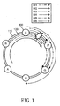
Fig. 1 shows a schematic configuration of a two-fiber optical ring network
according to a preferred embodiment of the present invention. As shown, the ring network
includes six nodes 200 and first and second fiber optic links 110 and 120 for connecting
these six nodes with one another. Although a limited number of nodes is shown in Fig. 1
for illustrative purposes, it is to be understood that the teachings of the present invention
can support a much larger number of nodes. Thus, the number of nodes in the drawing
should not impose limitations on the scope of the invention.
The ring network is a two-fiber wavelength division multiplexing (WDM) optical
ring network with a clockwise ring structure and a counterclockwise ring and maintains a
full-mesh connectivity with respect to all nodes 200. Fig. 1 shows an optical path of the
first fiber optic link 110 which functions as a transmission medium of optical signals
traveling in a clockwise direction and an optical path of the second fiber optic link 120
which functions as a transmission medium for optical signals traveling in a
counterclockwise direction. Further, the ring network is configured so that network
extension can be performed for additional new nodes, and that a rapid switching restoration
can be performed by switching the network links, as explained later.
In operation, when the optical path of the first fiber
optic link 110 is set to reverse
its two points, i.e., a starting point and a terminating point, the first
optical path 110 may
become the optical path for the second fiber
optic link 120. The clockwise optical path,
which starts with node B and terminate at node F, is set to the first fiber
optic link 110, the
counterclockwise optical path, which starts with the node F and terminate at node B, is set
to the second fiber
optic link 120. Note that the clockwise optical path corresponds to a
third wavelength W3 as the following Table 1.
| | A | B | C | F | G | H |
| W1 |
| | 1 | 3 | X | X | 2 | X |
| W2 | 3 | X | X | | 1 | 1 | 1 |
| W3 | X | 2 | X | 2 | X | 2 |
| W4 | 2 | X | 1 | 3 | X | X |
| W5 | X |
| | 1 | 2 | X | 3 | X |
| W6 | X | X | 3 | X | X | 3 |
Table 1 is a matrix showing how the optical path of the first fiber optic link 110 is
set in the optical ring network. Note that the optical path, as shown in Fig. 1, which passes
the first fiber optic link 110 between node C and node F is shown on the basis of the above
matrix for setting the optical path.
According to the embodiment of the present invention, each fiber optic link is
provided with working channels under a normal condition and protection channels under a
switched condition. The following Table 2 represents which wavelength is allocated to two
kinds of channels in the ring network.
| Wavelength | Direction | Channel |
| W1 to W16 | Clockwise | Working |
| W17 to W32 | Clockwise | Protection |
| W1 toW16 | Counterclockwise | Working |
| W17 to W32 | Counterclockwise | Protection |
As shown in Table 2, wavelengths for the working channels are different from
wavelengths for the protection channels. Thus, even when a fiber optic link switching
occurs, i.e., one fiber optic link is switched with another fiber optic link so as to reverse
transmission directions, it is possible to perform switching restoration without any
influence on the existing channel under a communication, which will be described in detail
below.
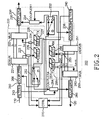
Fig. 2 illustrates a detailed diagram of the components that is representative to any
one of nodes shown in Fig. 1. As shown, each node 200 includes first and second splitting
sections 210 and 240, first and second add/ drop sections 220 and 250, first and second
switching sections 230 and 260, and a controlling section 270.
The first splitting section 210 functions to split optical signals traveling through
the first fiber optic link 110 into a protection channel. Specifically, the first splitting section
210 is fitted on the first fiber optic link 110 and severs to provide the protection channel for
the optical signals. In an alternate embodiment, the first splitting section 210 may be
replaced with an optical filter, such as a band-pass filter, a WDM coupler and so forth.
The first add/drop section 220 performs the adding and/or dropping of a channel
during the course of demultiplexing and multiplexing of the optical signals, from which
protection channels has been removed through the first splitting section 210. The first
add/drop section 220 includes a first demultiplexer 221, first and second tap couplers 223
and 224, a first optical transceiver module 225 having a first optical receiver 226 and a first
optical transmitter 227, and a first multiplexer 222.
The first demultiplexer 221 performs the wavelength division demultiplexing of
optical signals that are inputted through the first splitting section 210, then outputs the
demultiplexed optical signals to a plurality of channels. In an alternate embodiment, the
first demultiplexer 221 may be substituted by an arrayed waveguide grating.
The first optical receiver 226 functions to detect dropped channels among the
channels outputted from the first demultiplexer 221. Note that the dropped channels are
outputted through a photoelectric conversion process. In an alternate embodiment, the first
optical receiver 226 may be substituted by a photodiode.
The first tap coupler 223 is installed on the path between the first demultiplexer
221 and the first optical receiver 226. The first tap coupler 223splits a part of the channel
inputted into the first optical receiver 226 to another split channel. The first optical
transmitter 227 outputs channels to be added. In an alternate embodiment, the first optical
transmitter 227 may be substituted by a laser diode.
The second tap coupler 224 is installed on the path between the first optical
transmitter 227 and the first multiplexer 222, splits a part of the channel outputted from the
first optical transmitter 227, and outputs the split channel.
The first multiplexer 222 performs the wavelength division multiplexing of the
channels inputted from the first demultiplexer 221 and the channels inputted from the first
optical transmitter 227, then outputs the wavelength division multiplexed channels.
The first switching section 230 functions to combine the optical signals in
protection channels with added/dropped optical signals traveling through the first fiber
optic link 110 when a no link failure between adjacent nodes occurs. The first switching
section 230 also functions to combine the optical signals in the protection channels with
optical signals traveling through the second fiber optic link 120 if a link failure between
adjacent nodes has occurred.
The first switching section 230 includes a first switch 232 and first to third
couplers 234 to 236. The first switch 232 functions to perform either passing or switching
of the signals in the protection channels inputted from the first splitting section 210. The
first coupler 234 combines the protection channels passing through the first switch 232 with
the optical signals in the protection channels inputted from the other second add/drop
section 250, then outputs the combined protection channels. Finally, the second coupler
235 combines the added/dropped optical signals inputted from the first multiplexer 222 and
the optical signals in the protection channels inputted from the first coupler 235, then
outputs the combined results.
With continued reference to Fig. 2, the third coupler 236 is installed between the
second splitting section 240 and the second add/drop section 250 and configured to
combine switched protection channels outputted from the first switch 232 with optical
signals outputted from the second splitting section 240.
The second splitting section 240 functions to split the optical signals traveling
through the second fiber optic link 120 into a protection channel. Specifically, the second
splitting section 240 is fitted on the second fiber optic link 120 and provides protection
channel for the optical signals.. In an alternate embodiment, the second splitting section
240 may be replaced with an optical filter, such as a band-pass filter, a WDM coupler and
so forth.
The second add/drop section 250 carries out adding and/or dropping of an channel
during the course of demultiplexing and multiplexing optical signals, from which protection
channels are removed while optical signals pass through the first splitting section 210. The
second add/drop section 250 includes a second demultiplexer 251, third and fourth tap
couplers 253 and 254, a second optical transceiver module 255 having a second optical
receiver 256 and a second optical transmitter 257, and a second multiplexer 252.
The second demultiplexer 251 performs the wavelength division demultiplexing of
optical signals that are inputted through the second splitting section 240 and outputs the
demultiplexed optical signals to a plurality of channels. In an alternate embodiment, the
second demultiplexer 251 may be substituted by an array waveguide grating.
The second optical receiver 256 functions to detect dropped channels among the
channels outputted from the second demultiplexer 251 and outputs the dropped channels
through photoelectric conversion. In an alternate embodiment, the second optical receiver
256 may be substituted by a photodiode.
The third tap coupler 253 is installed on the path between the second
demultiplexer 251 and the second optical receiver 256 and functions to split a part of the
channel inputted into the second optical receiver 256, then outputs the split channel.
The second optical transmitter 257 outputs channels to be added. In an alternate
embodiment, the second optical transmitter 257 may be substituted for, by a laser diode for
example.
The fourth tap coupler 254 is installed on the path between the second optical
transmitter 257 and the second multiplexer 252 and functions to split a part of the channel
outputted from the second optical transmitter 257, then outputs the split channel.
The second multiplexer 252 performs the wavelength division multiplexing of the
channels inputted from the second demultiplexer 251 and of the channels inputted from the
second optical transmitter 257 and then outputs the wavelength division multiplexed
channels.
The second switching section 260 functions to combine the optical signals in the
protection channels with added/dropped optical signals traveling through the second fiber
optic link 120 when a no link failure between adjacent nodes occurs. The second switching
section 260 also functions to combine optical signals in the protection channels with optical
signals traveling through the first fiber optic link 110 if a link failure between adjacent
nodes has occurred.
The second switching section 260 includes a second switch 262 and fourth to sixth
couplers 264 to 266. The second switch 262 functions to perform either passing or
switching of protection channels inputted from the second splitting section 240. The fourth
coupler 264 combines the protection channels passing through the second switch 262 with
the optical signals in the protection channels inputted from the first add/drop section 220,
then outputs the combined protection channels. The fifth coupler 265 combines the
added/dropped optical signals inputted from the second multiplexer 252 and the optical
signals in the protection channels inputted from the fourth coupler 264, then outputs the
combined results. The sixth coupler 266 is installed between the first splitting section 210
and the first add/drop section 220 and combines switched protection channels outputted
from the second switch 262 with optical signals outputted from the first splitting section
210.
The controlling section 270 controls the first switch 232, the second switch 262,
the first optical transceiver module 225, and the second optical transceiver module 255 so
as to identify and restore a failing link. When a failure occurs on a certain link on the ring
network, a certain channel involved in the link with the failure occurring thereon cannot
reach the node in interest. As such, the controlling section 270 identifies the link failure
through the first or third tap coupler 223 or 253.
When there is a channel which fails to be transmitted under the influence of the
failing link, a loop-back procedure is performed using the protection channels of the first or
second optical transmitter 227 or 257. Specifically, the loop-back procedure is performed
by outputting the protection channels, outputted from the first or second optical transmitter
227 or 257, to the other fiber optic link. Here, the optical signals in the protection channels
are combined with optical signals traveling through the other fiber optic link.
When the optical signals reach at the next node, the optical signals pass through
the first or second splitting section 210 or 240. The first or second splitting section 210 or
240 acts to split the protection channels from the inputted optical signals. The protection
channels split in this way are inputted into the first or second switch 232 or 262, and the
rest of the optical signals are inputted into the first or second demultiplexer 221 or 251. At
this time, the controlling section 270 controls the first or second switch 232 or 262. When
the concerned node is not the adjacent node of the failing link, the controlling section 270
causes the first or second switch 232 or 262 to be in a parallel state, thus simply passing the
protection channels. However, when the concerned node is the adjacent node of the failing
link, the controlling section 270 causes the first or second switch 232 or 262 to be in a cross
state, thus performing a feed-back of the protection channels to the first or second
demultiplexer 221 or 251 which is installed on the other fiber optic link so that the
switching restoration is carried out.
Now, In order to facilitate an understanding of this invention, an exemplary working
process of restoring and switching will be described in conjunction with Figs. 3 and 4.
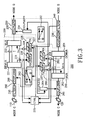
Fig. 3 illustrates a procedure of switching restoration of the node F when a failure
occurs on a fiber optic link between the nodes C and F in the optical fiber network shown in
Fig. 1. The first optical receiver 226 receives channels dropped by the first demultiplexer
221 before a failure occurs on the fiber optic link, but not immediately after a failure occurs
on the fiber optic link. The first tap coupler 223 does not split and output the channel after a
failure occurs on the fiber optic link. As such, when the controlling section 270 does not
receives optical signals that are split from the first tap coupler 223, the controlling section
identifies that the fiber optic link has failed. The controlling section 270 performs
switching restoration consisting of a loop-back procedure and a feed-back procedure as
soon as the controlling section identifies the link failure.
In the loop-back procedure, the controlling section 270 outputs a control signal to
the second optical transmitter 257, so that the second optical transmitter 257 outputs
protection channels. The optical signals in the protection channels pass through the first
coupler 234 to be inputted into the second coupler 235. The second coupler 235 combines
the protection channels with optical signals inputted from the first multiplexer 222, then
outputs the combined results.
In the feed-back procedure, the second splitting section 240 splits inputted optical
signals into the protection channels. To this end, the controlling section 270 outputs a
control signal so as to operate the second switch 262 in a cross state. Then, the optical
signals in the protection channels switched by the second switch 262 pass through the sixth
coupler 266 to be inputted into the first demultiplexer 221.
Fig. 4 illustrates operations of the nodes G, H, A and B when a failure occurs on a
fiber optic link between the nodes C and F in the optical fiber network shown in Fig. 1.
The first splitting section 210 splits inputted optical signals into the protection channels and
passes the rest of the optical signals therethrough. The first switch 232 is in a parallel state,
so that the optical signals in the protection channels pass through the first switch 232 and
the first coupler 234 to be inputted into the second coupler 235. The second coupler 235
combines the optical signals in the protection channels with optical signals outputted from
the first multiplexer 222, then outputs the combined results. Similarly, the optical signals
split into the protection channels from the second splitting section 240 pass through the
second switch 262 being in a parallel state and the fourth coupler 264, to be inputted into
the fifth coupler 265. The fifth coupler 265 combines the optical singles in the protection
channels with optical signals outputted from the second multiplexer 252, then outputs the
combined results.
As mentioned above, in the optical ring network, the protection channels are fed
back into the first or
second demultiplexer 221 or 251 at the adjacent node of the fiber optic
link that is subjected to switching, so that the protection channels are each set to have the
desired optical path before the switching occurs. It is a function of switching restoration
that the WDM optical ring network requires as an indispensable function. This switching
restoration mechanism provides a means of restoring any fiber optic link that is broken or
problematic. To perform a rapid switching restoration in the ring network, channels that
are demultiplexed and dropped are detected using the first or
third tap coupler 223 or 253.
The dropped channels are outputted to the controlling
section 270, which checks whether or
not it has received the dropped channels and then identifies the dropped channels. The
following Table 3 is a matrix that shows how to set the optical path of second
fiber optic
link 120.
| | A | B | C | F | G | H |
| W1 | 2 | 1 | X | X | 3 | X |
| W2 | 1 | X | X | 3 | 1 | 1 |
| W3 | X | 2 | X | 2 | X | 2 |
| W4 | 3 | X | 2 | 1 | X | X |
| W5 | X | 3 | 1 | X | 2 | X |
| W6 | X | X | 3 | X | X | 3 |
As seen from Tables 1 and 3, when any link fails, each node 200 cannot receive
some channels depending on the position of the failing link before switching restoration is
performed. As shown in Fig. 2, each node 200 is designed to always check for the light
intensity of each channel by providing the first or third tap coupler 223 or 253 to the
dropped channel. When this is identified by each channel at any node to determined the
failing link, a proper switching can be performed according to the teachings of the present
invention. Therefore, when any link fails, this link failure is identified simultaneously at
every node 200, and this identification process enables a proper measure to be taken at the
concerned node at the same time, thus reducing the time for performing switching
restoration as a whole.
As mentioned above, there is an advantage in that the optical ring network
according to the present invention saves expenses related to configure each node by
decreasing the number of the wavelength division multiplexer as in the conventional art.
There is another advantage in that the number of wavelengths necessary for connecting all
nodes in the optical ring network is less than that of UWPSR(or BWLSR),. Further, there
is yet another advantage in that the optical ring network enables switching restoration to be
rapidly performed by identifying channels that are dropped at the concerned node through a
path setting approach of BWPSR. Finally, there is still another advantage in that the optical
ring network according to the present invention splits multiplexed optical signals inputted
through the fiber optic link into the protection channel and performs either switching of the
protection channels or changing of the optical paths, so that the number of channels that
multiplexer and demultiplxer of the optical add/drop section must process can be decreased.