EP1411600A1 - Solenoid electrical connection and electrical spring terminal therefor - Google Patents
Solenoid electrical connection and electrical spring terminal therefor Download PDFInfo
- Publication number
- EP1411600A1 EP1411600A1 EP20030022974 EP03022974A EP1411600A1 EP 1411600 A1 EP1411600 A1 EP 1411600A1 EP 20030022974 EP20030022974 EP 20030022974 EP 03022974 A EP03022974 A EP 03022974A EP 1411600 A1 EP1411600 A1 EP 1411600A1
- Authority
- EP
- European Patent Office
- Prior art keywords
- strip
- forming
- terminal assembly
- overmold
- solenoid
- Prior art date
- Legal status (The legal status is an assumption and is not a legal conclusion. Google has not performed a legal analysis and makes no representation as to the accuracy of the status listed.)
- Withdrawn
Links
- 239000000463 material Substances 0.000 claims description 9
- 238000003780 insertion Methods 0.000 claims description 7
- 230000037431 insertion Effects 0.000 claims description 7
- 239000011810 insulating material Substances 0.000 claims description 5
- 239000013536 elastomeric material Substances 0.000 claims description 4
- 239000004020 conductor Substances 0.000 claims description 3
- RYGMFSIKBFXOCR-UHFFFAOYSA-N Copper Chemical compound [Cu] RYGMFSIKBFXOCR-UHFFFAOYSA-N 0.000 claims description 2
- 229910052802 copper Inorganic materials 0.000 claims description 2
- 239000010949 copper Substances 0.000 claims description 2
- 238000000034 method Methods 0.000 claims 6
- 238000004519 manufacturing process Methods 0.000 claims 1
- 239000012212 insulator Substances 0.000 abstract description 6
- 239000006096 absorbing agent Substances 0.000 description 13
- 230000035939 shock Effects 0.000 description 13
- 238000009434 installation Methods 0.000 description 7
- 239000000725 suspension Substances 0.000 description 3
- 239000002184 metal Substances 0.000 description 2
- 229910052751 metal Inorganic materials 0.000 description 2
- 230000015572 biosynthetic process Effects 0.000 description 1
- 230000006835 compression Effects 0.000 description 1
- 238000007906 compression Methods 0.000 description 1
- 239000012530 fluid Substances 0.000 description 1
- 238000002955 isolation Methods 0.000 description 1
- 230000014759 maintenance of location Effects 0.000 description 1
- 230000013011 mating Effects 0.000 description 1
- 230000004048 modification Effects 0.000 description 1
- 238000012986 modification Methods 0.000 description 1
- 230000002028 premature Effects 0.000 description 1
Images
Classifications
-
- H—ELECTRICITY
- H01—ELECTRIC ELEMENTS
- H01R—ELECTRICALLY-CONDUCTIVE CONNECTIONS; STRUCTURAL ASSOCIATIONS OF A PLURALITY OF MUTUALLY-INSULATED ELECTRICAL CONNECTING ELEMENTS; COUPLING DEVICES; CURRENT COLLECTORS
- H01R13/00—Details of coupling devices of the kinds covered by groups H01R12/70 or H01R24/00 - H01R33/00
- H01R13/73—Means for mounting coupling parts to apparatus or structures, e.g. to a wall
- H01R13/74—Means for mounting coupling parts in openings of a panel
- H01R13/741—Means for mounting coupling parts in openings of a panel using snap fastening means
- H01R13/743—Means for mounting coupling parts in openings of a panel using snap fastening means integral with the housing
-
- H—ELECTRICITY
- H01—ELECTRIC ELEMENTS
- H01R—ELECTRICALLY-CONDUCTIVE CONNECTIONS; STRUCTURAL ASSOCIATIONS OF A PLURALITY OF MUTUALLY-INSULATED ELECTRICAL CONNECTING ELEMENTS; COUPLING DEVICES; CURRENT COLLECTORS
- H01R13/00—Details of coupling devices of the kinds covered by groups H01R12/70 or H01R24/00 - H01R33/00
- H01R13/40—Securing contact members in or to a base or case; Insulating of contact members
- H01R13/405—Securing in non-demountable manner, e.g. moulding, riveting
-
- H—ELECTRICITY
- H01—ELECTRIC ELEMENTS
- H01R—ELECTRICALLY-CONDUCTIVE CONNECTIONS; STRUCTURAL ASSOCIATIONS OF A PLURALITY OF MUTUALLY-INSULATED ELECTRICAL CONNECTING ELEMENTS; COUPLING DEVICES; CURRENT COLLECTORS
- H01R43/00—Apparatus or processes specially adapted for manufacturing, assembling, maintaining, or repairing of line connectors or current collectors or for joining electric conductors
- H01R43/20—Apparatus or processes specially adapted for manufacturing, assembling, maintaining, or repairing of line connectors or current collectors or for joining electric conductors for assembling or disassembling contact members with insulating base, case or sleeve
- H01R43/24—Assembling by moulding on contact members
-
- H—ELECTRICITY
- H01—ELECTRIC ELEMENTS
- H01R—ELECTRICALLY-CONDUCTIVE CONNECTIONS; STRUCTURAL ASSOCIATIONS OF A PLURALITY OF MUTUALLY-INSULATED ELECTRICAL CONNECTING ELEMENTS; COUPLING DEVICES; CURRENT COLLECTORS
- H01R13/00—Details of coupling devices of the kinds covered by groups H01R12/70 or H01R24/00 - H01R33/00
- H01R13/02—Contact members
- H01R13/22—Contacts for co-operating by abutting
- H01R13/24—Contacts for co-operating by abutting resilient; resiliently-mounted
-
- H—ELECTRICITY
- H01—ELECTRIC ELEMENTS
- H01R—ELECTRICALLY-CONDUCTIVE CONNECTIONS; STRUCTURAL ASSOCIATIONS OF A PLURALITY OF MUTUALLY-INSULATED ELECTRICAL CONNECTING ELEMENTS; COUPLING DEVICES; CURRENT COLLECTORS
- H01R4/00—Electrically-conductive connections between two or more conductive members in direct contact, i.e. touching one another; Means for effecting or maintaining such contact; Electrically-conductive connections having two or more spaced connecting locations for conductors and using contact members penetrating insulation
- H01R4/24—Connections using contact members penetrating or cutting insulation or cable strands
- H01R4/2416—Connections using contact members penetrating or cutting insulation or cable strands the contact members having insulation-cutting edges, e.g. of tuning fork type
- H01R4/242—Connections using contact members penetrating or cutting insulation or cable strands the contact members having insulation-cutting edges, e.g. of tuning fork type the contact members being plates having a single slot
- H01R4/2425—Flat plates, e.g. multi-layered flat plates
Definitions
- the present invention relates to electrical connector terminals and particularly terminals for use with solenoid operators and more particularly for providing energization of the solenoid by making electrical connection through a mechanical operating member of the operating system into which the solenoid is assembled.
- An example of such a device is a solenoid operated dampening or flow restricting valve associated with an hydraulic shock absorber for a vehicle suspension wherein a mechanical member associated with the moveable parts of the shock absorber provides electrical contact for energizing the solenoid operated dampening valve in response to a control signal.
- the solenoid operated valve is operable to restrict the flow of hydraulic fluid in the shock absorber to alter the rate of flow and thus the dampening in the shock absorber.
- Such arrangements are employed in motor vehicle suspensions where it is desired to alter the stiffness or dampening rate of the shock absorbers in real time or on a running basis in response to changes in road conditions or driving patterns.
- the present invention provides an electrical terminal adapted for external contact and connected by bayonet or plug-in connection with a solenoid coil when the terminal is installed in a valve operated by the solenoid.
- the terminal is installed in the attachment portion of the valve body for connection therewith upon assembly of the body into the system to be controlled by the valve, such as a shock absorber.
- the present invention provides a spring type electrical terminal for mounting through an aperture and having a right angle configuration for effecting a plug-in connection thereto by a coil.
- the spring terminal has a hooked or folded end capable of absorbing contact by an external contact member upon installation in a structure, such as a shock absorber piston rod contact.
- the region of the terminal adjacent the hooked or folded end is formed with a contra curvature which cooperates with the hooked portion for lowering the lateral spring rate and absorbing deflection by the external contact.
- Insulating material is disposed over the right angle bend for enabling mounting of the terminal through an aperture in a metal valve body.
- the insulating material is plastic molded over the terminal and alternatively may be formed of or may include elastomeric material.
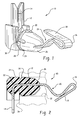
- FIG. 1 is a perspective view of the terminal assembly of the present invention
- FIG. 2 is a cross-section of the terminal assembly of FIG. 1;
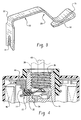
- FIG. 3 is a perspective view of the spring terminal portion of the terminal of FIG. 1 prior to overmolding.
- FIG. 4 is a cross-section of a portion of a solenoid operated valve showing the installation of the terminal assembly of FIG. 1 therein.
- the terminal assembly of the present invention is indicated generally at 10 and includes a deflectable terminal member formed of a strip of preferably spring tempered material indicated generally at 12.
- strip 12 has a relatively thin rectangular shape in transverse section.
- the strip may be formed of a continuous length of relatively thin material having a generally flat transverse section.
- the strip 12 may be formed of material consisting essentially of copper.
- Terminal member 12 has a bifurcated end 14 formed generally at right angles to the central portion of the terminal member 12 which bifurcated end 14 is adapted for bayonet or plug-in type connection thereto.
- the member 12 has a hook or folded portion 16 formed in the end thereof remote from bifurcation 14; and, the hook preferably has the open end thereof formed in a straight or planar configuration as denoted by reference numeral 18.
- the member 12 has a region indicated generally at 20 which is formed in contra curvature e.g. that has a reversal of curvature therein or S-shape, which portion 20 in conjunction with hook 16 provides for improved deflectability or lowered lateral spring rate for the terminal member 12.
- the portion of the member 12 between contra curvature 20 and the bifurcated end 14 has a right angle bend 22 which has an insulator 24 formed thereon preferably by overmolding.
- the insulator 24 is preferably formed of plastic material but alternately may be formed of or may include elastomeric material.
- the insulator 24 has the end portion thereof adjacent contra curvature 20 provided with an annular taper 26 to facilitate installation as hereinafter will be described.
- the insulator 24 has an annular rib 28 formed thereon with a plurality of tapered deformable lugs adjacent thereto and spaced circumferentially thereabout to facilitate installation and retention.
- the terminal assembly is shown installed in an aperture 32 formed in a valve body 34 by insertion of the hooked end of the terminal through the aperture and engaging the sides of the aperture with the rib 28 and lugs 30 by compression thereof, thereby frictionally retaining the terminal assembly in the aperture 32.
- the hook 16 and straight portion 18 extend into a threaded bore 36 formed in the valve body.
- the hook is deflected to close and move laterally to the position shown in dashed outline in FIG. 4 upon being contacted by the end of an electrical conductor 40 extending through external member 38 threadedly engaging bore 36 as shown in dashed line in FIG. 4.
- member 38 is the piston rod of an hydraulic shock absorber, but may alternatively be any structural mounting member as for applications other than shock absorbers.
- the bifurcated portion 14 of the terminal 12 is engaged in plug-in arrangement with a corresponding electrical terminal receptacle 44 provided with the solenoid coil 46.
- the present invention thus provides a unique electrical terminal assembly which is capable of being installed through an aperture in a solenoid operated valve and extending into a limited space for making electrical contact with an external contact on an attachment structure engaging the solenoid valve.
- the terminal strip of the present invention is overmolded with insulating material and the strip has a region of contra curvature adjacent a hook shaped contact end for lowering the stiffness or lateral spring rate of the terminal.
- One end of the strip is bifurcated for plug-in connection to a solenoid coil on the valve body.
- the present invention thus provides a unique and relatively low cost terminal contact for insertion in a valve body and for plug-in connection with the solenoid coil upon assembly to the valve body.
Landscapes
- Engineering & Computer Science (AREA)
- Manufacturing & Machinery (AREA)
- Magnetically Actuated Valves (AREA)
Abstract
Description
- The present invention relates to electrical connector terminals and particularly terminals for use with solenoid operators and more particularly for providing energization of the solenoid by making electrical connection through a mechanical operating member of the operating system into which the solenoid is assembled. An example of such a device is a solenoid operated dampening or flow restricting valve associated with an hydraulic shock absorber for a vehicle suspension wherein a mechanical member associated with the moveable parts of the shock absorber provides electrical contact for energizing the solenoid operated dampening valve in response to a control signal. In such shock absorber applications, the solenoid operated valve is operable to restrict the flow of hydraulic fluid in the shock absorber to alter the rate of flow and thus the dampening in the shock absorber. Such arrangements are employed in motor vehicle suspensions where it is desired to alter the stiffness or dampening rate of the shock absorbers in real time or on a running basis in response to changes in road conditions or driving patterns.
- Heretofore in such vehicle suspension shock absorber application problems have been encountered with undesired movement of electrical contacts providing current to the solenoid coil from the deformation and relative movement between the shock absorber components which has resulted in permanent deformation of the contacts and early failure of the contacts. This problem has been particularly prominent in installations where the solenoid contact terminal is disposed in the attachment fitting portion of the solenoid valve body which is attached to the structural member such as the piston rod of a motor vehicle shock absorber. Heretofore, in solenoid valves for such installations, the contact terminal has been inserted through an aperture in the solenoid operated valve body such that upon assembly of a solenoid coil thereover the terminal makes a bayonet style or plug-in connection with a mating terminal on the solenoid coil. The electrical terminal has been provided with an insulator thereabout for insertion into an aperture in the attachment portion of the valve body and electrical isolation of the terminal from the valve body, which is typically formed of metal.
- In such an aforesaid installation, it has been found extremely difficult to provide adequate deflectability or sufficiently low lateral spring rate of the electrical terminal to accommodate relative movement of the structural components because of the minimum space available for the formation of the electrical terminal in the mounting on the valve body. Thus, it has long been desired to provide an electrical terminal in a solenoid which is capable of withstanding the deformation without premature failure when subjected to high inertial loading caused by relative movement of the components of the systems in which the valve is installed.
- The present invention provides an electrical terminal adapted for external contact and connected by bayonet or plug-in connection with a solenoid coil when the terminal is installed in a valve operated by the solenoid. The terminal is installed in the attachment portion of the valve body for connection therewith upon assembly of the body into the system to be controlled by the valve, such as a shock absorber.
- The present invention provides a spring type electrical terminal for mounting through an aperture and having a right angle configuration for effecting a plug-in connection thereto by a coil. The spring terminal has a hooked or folded end capable of absorbing contact by an external contact member upon installation in a structure, such as a shock absorber piston rod contact. The region of the terminal adjacent the hooked or folded end is formed with a contra curvature which cooperates with the hooked portion for lowering the lateral spring rate and absorbing deflection by the external contact. Insulating material is disposed over the right angle bend for enabling mounting of the terminal through an aperture in a metal valve body. In the presently preferred practice, the insulating material is plastic molded over the terminal and alternatively may be formed of or may include elastomeric material.
- FIG. 1 is a perspective view of the terminal assembly of the present invention;
- FIG. 2 is a cross-section of the terminal assembly of FIG. 1;
- FIG. 3 is a perspective view of the spring terminal portion of the terminal of FIG. 1 prior to overmolding; and,
- FIG. 4 is a cross-section of a portion of a solenoid operated valve showing the installation of the terminal assembly of FIG. 1 therein.
- Referring to FIGS. 1 through 3, the terminal assembly of the present invention is indicated generally at 10 and includes a deflectable terminal member formed of a strip of preferably spring tempered material indicated generally at 12.
- In the presently preferred practice,
strip 12 has a relatively thin rectangular shape in transverse section. The strip may be formed of a continuous length of relatively thin material having a generally flat transverse section. Thestrip 12 may be formed of material consisting essentially of copper. -
Terminal member 12 has a bifurcatedend 14 formed generally at right angles to the central portion of theterminal member 12 which bifurcatedend 14 is adapted for bayonet or plug-in type connection thereto. Themember 12 has a hook or foldedportion 16 formed in the end thereof remote frombifurcation 14; and, the hook preferably has the open end thereof formed in a straight or planar configuration as denoted byreference numeral 18. Themember 12 has a region indicated generally at 20 which is formed in contra curvature e.g. that has a reversal of curvature therein or S-shape, whichportion 20 in conjunction withhook 16 provides for improved deflectability or lowered lateral spring rate for theterminal member 12. - The portion of the
member 12 betweencontra curvature 20 and the bifurcatedend 14 has aright angle bend 22 which has aninsulator 24 formed thereon preferably by overmolding. Theinsulator 24 is preferably formed of plastic material but alternately may be formed of or may include elastomeric material. Theinsulator 24 has the end portion thereofadjacent contra curvature 20 provided with anannular taper 26 to facilitate installation as hereinafter will be described. In the presently preferred practice, theinsulator 24 has anannular rib 28 formed thereon with a plurality of tapered deformable lugs adjacent thereto and spaced circumferentially thereabout to facilitate installation and retention. - Referring to FIG. 4, the terminal assembly is shown installed in an
aperture 32 formed in avalve body 34 by insertion of the hooked end of the terminal through the aperture and engaging the sides of the aperture with therib 28 andlugs 30 by compression thereof, thereby frictionally retaining the terminal assembly in theaperture 32. Thehook 16 andstraight portion 18 extend into a threadedbore 36 formed in the valve body. In operation, the hook is deflected to close and move laterally to the position shown in dashed outline in FIG. 4 upon being contacted by the end of anelectrical conductor 40 extending throughexternal member 38 threadedly engagingbore 36 as shown in dashed line in FIG. 4. In the present practice of theinvention member 38 is the piston rod of an hydraulic shock absorber, but may alternatively be any structural mounting member as for applications other than shock absorbers. - Upon assembly of a
coil 46 overbody 34, the bifurcatedportion 14 of theterminal 12 is engaged in plug-in arrangement with a correspondingelectrical terminal receptacle 44 provided with thesolenoid coil 46. - The present invention thus provides a unique electrical terminal assembly which is capable of being installed through an aperture in a solenoid operated valve and extending into a limited space for making electrical contact with an external contact on an attachment structure engaging the solenoid valve. The terminal strip of the present invention is overmolded with insulating material and the strip has a region of contra curvature adjacent a hook shaped contact end for lowering the stiffness or lateral spring rate of the terminal. One end of the strip is bifurcated for plug-in connection to a solenoid coil on the valve body.
- The present invention thus provides a unique and relatively low cost terminal contact for insertion in a valve body and for plug-in connection with the solenoid coil upon assembly to the valve body.
- Although the invention has hereinabove been described with respect to the illustrated embodiments, it will be understood that the invention is capable of modification and variation and is limited only by the following claims.
Claims (17)
- A connector terminal assembly for insertion in an aperture in a solenoid comprising:(a) an elongated strip of electrically conductive material with a generally right angle bend in the region of one end thereof and a hooked configuration at an end opposite said one end;(b) a region of contracurvature formed adjacent said hooked configuration; and,(c) an overmold of insulating material formed over said right angle bend and having a mounting surface thereon adapted for insertion in a mounting aperture in the direction of said hooked configuration.
- The terminal assembly defined in claim 1, wherein said overmold is formed of plastic material.
- The terminal assembly defined in claim 1, wherein said overmold includes elastomeric material.
- The terminal assembly defined in claim 1, wherein said overmold mounting surface includes a tapered portion adjacent said contracurvature.
- The terminal assembly defined in claim 1, wherein said strip is bifurcated at said one end and said overmold is relieved to expose opposing edges of said bifurcation.
- The terminal assembly defined in claim 1, wherein said strip has a relatively thin rectangular shape in transverse section.
- The terminal assembly defined in claim 1, wherein said overmold mounting surface includes a generally cylindrical portion with an annular tapered portion for facilitating insertion into a mounting aperture.
- The terminal assembly defined in claim 1, wherein said strip is formed of a continuous length of relatively thin material having a generally flat transverse section.
- The terminal assembly defined in claim 1, wherein said strip is formed of material having a spring temper.
- The terminal assembly defined in claim 1, wherein said strip is formed of material consisting essentially of copper.
- A method of making a connector terminal assembly for a solenoid comprising:(a) forming an elongated strip of electrically conductive material;(b) forming a generally right angle bend in one end of the strip;(c) forming a hook in an end of the strip opposite the one end;(d) forming a region of contracurvature adjacent said hook of said strip; and,(e) overmolding said right angle bend with insulating material and forming a mounting surface on the overmolding for insertion in an aperture in the direction of said looped end.
- The method defined in claim 11, wherein said step of forming a mounting surface includes forming a generally cylindrical tapered surface.
- The method defined in claim 12, wherein said step of forming a generally cylindrical tapered surface includes forming an annular rib.
- The method defined in claim 11, wherein said step of overmolding includes overmolding with elastomeric material.
- The method defined in claim 11, wherein said step of forming an elongated strip includes forming a strip of spring temper material.
- The method defined in claim 11, further comprising bifurcating said one end and exposing said bifurcation from said overmolding.
- The method defined in claim 11, wherein said step of forming a region of contracurvature includes forming an S-shape configuration.
Applications Claiming Priority (2)
| Application Number | Priority Date | Filing Date | Title |
|---|---|---|---|
| US10/271,913 US6837736B2 (en) | 2002-10-15 | 2002-10-15 | Solenoid electrical connection and electrical spring terminal therefor |
| US271913 | 2002-10-15 |
Publications (1)
| Publication Number | Publication Date |
|---|---|
| EP1411600A1 true EP1411600A1 (en) | 2004-04-21 |
Family
ID=32042925
Family Applications (1)
| Application Number | Title | Priority Date | Filing Date |
|---|---|---|---|
| EP20030022974 Withdrawn EP1411600A1 (en) | 2002-10-15 | 2003-10-09 | Solenoid electrical connection and electrical spring terminal therefor |
Country Status (4)
| Country | Link |
|---|---|
| US (1) | US6837736B2 (en) |
| EP (1) | EP1411600A1 (en) |
| CA (1) | CA2444173A1 (en) |
| MX (1) | MXPA03009419A (en) |
Families Citing this family (1)
| Publication number | Priority date | Publication date | Assignee | Title |
|---|---|---|---|---|
| EP1821587B1 (en) * | 2006-02-20 | 2017-08-02 | Denso Corporation | Electronic component mounting structure |
Citations (3)
| Publication number | Priority date | Publication date | Assignee | Title |
|---|---|---|---|---|
| US5241746A (en) * | 1991-06-25 | 1993-09-07 | Illinois Tool Works Inc. | Threaded receptacle manufacturing method including mounting of electrical contact members within the receptacle |
| EP1172903A1 (en) * | 2000-07-11 | 2002-01-16 | Sumitomo Wiring Systems, Ltd. | Waterproofing configuration for a lighting fixture |
| US20020142630A1 (en) * | 2001-03-28 | 2002-10-03 | Molus Richard J. | Through panel wiring system |
Family Cites Families (1)
| Publication number | Priority date | Publication date | Assignee | Title |
|---|---|---|---|---|
| US6379162B1 (en) * | 2000-07-27 | 2002-04-30 | Delphi Technologies, Inc. | Electrical connector system |
-
2002
- 2002-10-15 US US10/271,913 patent/US6837736B2/en not_active Expired - Fee Related
-
2003
- 2003-10-03 CA CA002444173A patent/CA2444173A1/en not_active Abandoned
- 2003-10-09 EP EP20030022974 patent/EP1411600A1/en not_active Withdrawn
- 2003-10-15 MX MXPA03009419A patent/MXPA03009419A/en unknown
Patent Citations (3)
| Publication number | Priority date | Publication date | Assignee | Title |
|---|---|---|---|---|
| US5241746A (en) * | 1991-06-25 | 1993-09-07 | Illinois Tool Works Inc. | Threaded receptacle manufacturing method including mounting of electrical contact members within the receptacle |
| EP1172903A1 (en) * | 2000-07-11 | 2002-01-16 | Sumitomo Wiring Systems, Ltd. | Waterproofing configuration for a lighting fixture |
| US20020142630A1 (en) * | 2001-03-28 | 2002-10-03 | Molus Richard J. | Through panel wiring system |
Also Published As
| Publication number | Publication date |
|---|---|
| US6837736B2 (en) | 2005-01-04 |
| MXPA03009419A (en) | 2004-12-07 |
| US20040072466A1 (en) | 2004-04-15 |
| CA2444173A1 (en) | 2004-04-15 |
Similar Documents
| Publication | Publication Date | Title |
|---|---|---|
| US8430696B2 (en) | Connector having improved fitting properties | |
| US6668810B1 (en) | Ignition coil assembly with spark plug connector | |
| US10148032B1 (en) | Sealed electrical connector assembly and wire seal | |
| US20140141634A1 (en) | Ground terminal and connector provided therewith | |
| JP4939713B2 (en) | Electro-hydraulic device for adjusting the brake pressure of hydraulic vehicle brake devices | |
| DE102009026816A1 (en) | Connection element and associated fluid assembly | |
| US5011426A (en) | Electrical connector assembly for vehicular suspension system component | |
| KR102394806B1 (en) | Device for operating horn of vehicle | |
| US5986368A (en) | Electrohydraulic unit and method for assembling an electrohydraulic unit | |
| KR19990013372A (en) | Hydraulic brake control | |
| EP3474386B1 (en) | An electrical connector comprising a flat electrical contact terminal | |
| JP4520915B2 (en) | Brake hydraulic pressure control device for vehicles | |
| US6837736B2 (en) | Solenoid electrical connection and electrical spring terminal therefor | |
| US6358071B1 (en) | Electrical connection for a spark plug and method of assembling the same | |
| JP6572189B2 (en) | Resin molded body | |
| JP2003510543A (en) | Structure for electrical contact of valve | |
| US4598971A (en) | Battery cable/connector assembly | |
| CN112534653A (en) | Assembly for electrical contacting and current connector | |
| EP1583191B1 (en) | High retention connection | |
| KR20150090089A (en) | Electric contact arrangement for contacting a coil | |
| EP1241055A2 (en) | Electrical connector for the steering wheel of a vehicle | |
| US20210005414A1 (en) | Electromagnetic relay | |
| KR100756098B1 (en) | Control unit for automatic transmission | |
| EP1073159A2 (en) | Switch device with AC inlet and AC switch | |
| EP0872864B1 (en) | Normally closed, pressure responsive electrical switch |
Legal Events
| Date | Code | Title | Description |
|---|---|---|---|
| PUAI | Public reference made under article 153(3) epc to a published international application that has entered the european phase |
Free format text: ORIGINAL CODE: 0009012 |
|
| AK | Designated contracting states |
Kind code of ref document: A1 Designated state(s): AT BE BG CH CY CZ DE DK EE ES FI FR GB GR HU IE IT LI LU MC NL PT RO SE SI SK TR |
|
| AX | Request for extension of the european patent |
Extension state: AL LT LV MK |
|
| 17P | Request for examination filed |
Effective date: 20040510 |
|
| 17Q | First examination report despatched |
Effective date: 20040708 |
|
| AKX | Designation fees paid |
Designated state(s): DE ES FR GB IT |
|
| GRAP | Despatch of communication of intention to grant a patent |
Free format text: ORIGINAL CODE: EPIDOSNIGR1 |
|
| STAA | Information on the status of an ep patent application or granted ep patent |
Free format text: STATUS: THE APPLICATION IS DEEMED TO BE WITHDRAWN |
|
| 18D | Application deemed to be withdrawn |
Effective date: 20070829 |