EP1411459B1 - Method and apparatus for extracting feature vector used for face recognition and retrieval - Google Patents
Method and apparatus for extracting feature vector used for face recognition and retrieval Download PDFInfo
- Publication number
- EP1411459B1 EP1411459B1 EP03256510A EP03256510A EP1411459B1 EP 1411459 B1 EP1411459 B1 EP 1411459B1 EP 03256510 A EP03256510 A EP 03256510A EP 03256510 A EP03256510 A EP 03256510A EP 1411459 B1 EP1411459 B1 EP 1411459B1
- Authority
- EP
- European Patent Office
- Prior art keywords
- feature vector
- fourier
- entire
- vector
- vectors
- Prior art date
- Legal status (The legal status is an assumption and is not a legal conclusion. Google has not performed a legal analysis and makes no representation as to the accuracy of the status listed.)
- Expired - Lifetime
Links
Images


Classifications
-
- G—PHYSICS
- G06—COMPUTING; CALCULATING OR COUNTING
- G06V—IMAGE OR VIDEO RECOGNITION OR UNDERSTANDING
- G06V40/00—Recognition of biometric, human-related or animal-related patterns in image or video data
- G06V40/10—Human or animal bodies, e.g. vehicle occupants or pedestrians; Body parts, e.g. hands
- G06V40/16—Human faces, e.g. facial parts, sketches or expressions
- G06V40/168—Feature extraction; Face representation
- G06V40/169—Holistic features and representations, i.e. based on the facial image taken as a whole
-
- G—PHYSICS
- G06—COMPUTING; CALCULATING OR COUNTING
- G06V—IMAGE OR VIDEO RECOGNITION OR UNDERSTANDING
- G06V40/00—Recognition of biometric, human-related or animal-related patterns in image or video data
- G06V40/10—Human or animal bodies, e.g. vehicle occupants or pedestrians; Body parts, e.g. hands
- G06V40/16—Human faces, e.g. facial parts, sketches or expressions
- G06V40/168—Feature extraction; Face representation
- G06V40/171—Local features and components; Facial parts ; Occluding parts, e.g. glasses; Geometrical relationships
Definitions
- the present invention relates to a face recognition and retrieval system, and more particularly, to a method and apparatus for extracting a feature vector used for face searching and recognition, which can overcome the limits of feature vectors generated in a frequency domain and a spatial domain by separately generating a Fourier feature vector and an intensity feature vector for a normalized face image and then merging the Fourier feature vector and the intensity feature vector.
- PCA principal component analysis
- the PCA-based face recognition technique is capable of recognizing a face image by extracting major feature vectors from the face image and classifying the face image into a predetermined category based on the extracted major feature vectors.
- this technique has problems, such as low recognition speed and low reliability. Even though this technique shows some degree of reliability irrespective of variations in the lightness of a face image, it has failed to provide reliable and satisfactory face recognition results for different face expressions and poses.
- a computer-readable recording medium on which a program enabling the method of extracting feature vectors for face recognition and retrieval is recorded.
- the present invention thus provides a method of extracting feature vectors for face recognition and retrieval, which can overcome the limits of feature vectors generated in a frequency domain and a spatial domain by separately generating a Fourier feature vector and an intensity feature vector for a normalized face image and then merging the Fourier feature vector and the intensity feature vector.
- the present invention also provides an apparatus for extracting a feature vector used for face recognition and retrieval, which uses the method of extracting feature vectors for face recognition and retrieval.
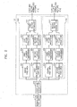
- FIG. 1 is a block diagram of an apparatus for extracting a feature vector used for face recognition and retrieval according to a preferred embodiment of the present invention.
- the apparatus is comprised of a frequency feature vector generation unit 120 and a composite feature vector generation unit 130.
- the frequency feature vector generation unit 120 includes a Fourier feature generation unit 121, an entire Fourier feature vector generation unit 123, and a central Fourier feature vector generation unit 125
- the composite feature vector generation unit 130 includes a Fourier feature generation unit 121, an intensity feature generation unit 131, an entire composite feature vector generation unit 133, and a central composite feature vector generation unit 135.
- a normalized face image 110 is obtained by scaling an original face image into, for example, 56 lines, in which case each line is comprised of, for example, 46 pixels.
- the center of the right eye in the original face image is located in the 24 th column and 16 th row of the normalized face image 110, and the center of the left eye is located in the 24 th column and 31 st row of the normalized face image 110.
- the Fourier feature generation unit 121 performs Fourier transformation on the normalized face image 110, i.e., an entire face area and a central face area, thus obtaining the Fourier spectra and Fourier amplitudes of the entire face area and the central face area, defines first and second feature vectors using the Fourier spectrum and Fourier amplitude of the entire face area, and defines third and fourth feature vectors using the Fourier spectrum and Fourier amplitude for the central face area.
- the first through fourth feature vectors are projected onto a principal component linear discriminant analysis (PCLDA) sub-space and then are normalized into unit vectors.
- the first and second normalized vectors are feature vectors for the entire face area
- the third and fourth normalized vectors are feature vectors for the central face area.
- Fourier feature vectors are obtained by encoding spatial relations between pixels constituting the normalized face image 110.
- the entire Fourier feature vector generation unit 123 combines the first and second normalized vectors, provided by the Fourier feature generation unit 121, into a single combined vector, projects the combined vector onto a discriminant space defined by a predetermined basis matrix, quantizes each component of the projected vector in a predetermined manner, and stores the quantized vector as an entire Fourier feature vector.
- the central Fourier feature vector generation unit 125 combines the third and fourth normalized vectors, provided by the Fourier feature generation unit 121, into a single combined vector, projects the combined vector onto a discriminant space defined by a predetermined basis matrix, quantizes each component of the projected vector in a predetermined manner, and stores the quantized vector as a central Fourier feature vector.
- the intensity feature generation unit 131 carries out pose estimation and compensation on the normalized face image 110, projects an entire face area and a predetermined number of components of the normalized face image 110, for example, 5 components of the normalized face image 110, among portions of the pose-compensated face image into the PCLDA sub-space, and normalizes the projection results into fifth and sixth unit vectors.
- An entire intensity feature vector for the entire face area is a fifth feature vector, which has been normalized into the fifth unit vector
- local intensity feature vectors for portions of the normalized face image 110 are sixth through tenth feature vectors, each of which has been normalized into the sixth unit vector.
- the intensity feature vectors are obtained by encoding variations in the intensity of the pixels constituting the entire face area and the five components of the normalized face image 110.
- the entire composite feature vector generation unit 133 combines the first and second normalized vectors, provided by the Fourier feature generation unit 121, and the entire intensity feature vector, provided by the intensity feature generation unit 131, into a single combined vector, projects the combined vector onto a discriminant space defined by a predetermined basis matrix, quantizes each component of the projected vector in a predetermined manner, and stores the quantized vector as an entire composite feature vector.
- the central composite feature vector generation unit 135 combines the third and fourth normalized vectors, provided by the Fourier feature generation unit 121, and the local intensity feature vectors, provided by the intensity feature generation unit 131, into a single combined vector, projects the combined vector onto a discriminant space defined by a predetermined basis matrix, quantizes each component of the projected vector in a predetermined manner, and stores the quantized vector as a central composite feature vector.
- FIG. 2 is a detailed block diagram of the Fourier feature generation unit 121 of FIG. 2 .
- the Fourier feature generation unit 121 includes a first image division unit 210, an entire Fourier feature vector generator 220, and a central Fourier feature vector generator 230.
- the entire Fourier feature vector generator 220 includes first and second Fourier transformers 222 and 225, first and second PCLDA projectors 223 and 226, and a first vector normalizer 227.
- the central Fourier feature vector generator 230 includes a third Fourier transformer 231, third and fourth PCLDA projectors 233 and 234, and a second vector normalizer 235.
- the first image division unit 210 divides the normalized face image 110 into an entire face area 221, a block-divided face area 224, and a central face area 231.
- the entire Fourier feature vector generator 220 obtains a Fourier spectrum of the entire face area 221 and Fourier amplitude of the block-divided face area 224 and then generates an entire Fourier feature vector using the Fourier spectrum and Fourier amplitude, a process which will become more apparent in the following paragraphs.
- the first Fourier transformer 222 performs Fourier transformation on the entire face area 221, thus converting the entire face area 221 into a frequency-domain component. Supposing that the entire face area 221 is represented by f(x, y), the Fourier spectrum F(u, v) can be expressed by the following equation.
- F (0, 0) indicates a DC component.
- Table 1 shows raster scanning parameters used for extracting feature vectors from a Fourier domain.
- Table 1 Feature Vector Feature Scan Area A Scan Area B Vector Dimension S A E A S B E B Subtotal Number of Blocks Total x 1 f Re [ F ( u , v )] (0, 0) (11, 13) (35, 0) (45, 13) 322 - 644 Im [ F ( u , v )] (0, 0) (11, 13) (35, 0) (45, 13) 322 - x 2 f F 1 0 u v (0, 0) (10, 13) (33, 0) (43, 13) 308 1 856 F k 1 u v (0, 0) (5, 6) (17, 0) (21, 6) 77 4 F k 2 u v (0, 0) (2, 2) (9, 0) (10, 2) 15 16 x 1 g Re [ G ( u , v )] (0,
- S A and S B represent starting points of the scanning areas A and B, respectively
- E A and E B represent ending points of the scanning areas A and B, respectively.
- Examples of the scanning areas A and B and the raster scanning are illustrated in FIG. 10 .
- Fourier components are extracted from the scanning areas A and B through raster scanning performed along a ' u ' direction.
- the first feature vector x 1 f which is obtained as a result of the raster scanning, can be expressed by Equation (2) below.
- the first feature vector x 1 f is a dimension of 644.
- the first PCLDA projector 223 projects the first feature vector x 1 f , obtained by the first Fourier transformer 222, onto a discriminant space obtained by carrying out PCLDA on the first feature vector x 1 f .
- the discriminant space is defined by a first basis matrix ⁇ 1 f , which is obtained using a predetermined well-known algorithm and is also well known to those skilled in the art.
- the second Fourier transformer 225 converts the block-divided face area 224 into a frequency domain by performing Fourier transformation on the block-divided face area 224.
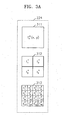
- the block-divided face area 224 includes three sub-spaces, i.e., an entire area 311, a four-block area 312, and a sixteen-block area 313.
- the Fourier transformation is performed on each of the sub-spaces of the block-divided face area 224.
- the entire area 311, represented by f 1 0 x y is obtained by removing boundary rows of the normalized face image 110 and clipping a resulting face image into a 44 ⁇ 56 image.
- f 1 0 x y can be represented by Equation (3) below.
- f 1 0 x y f ⁇ x + 1 , y
- the four-block area 312, which is represented by f k 1 x y , and the sixteen-block area 313, which is represented by f k 2 x y , are obtained using the entire area 311. Specifically, the four-block area 312 is obtained by dividing the entire area 311 into four identical blocks having a 22 ⁇ 28 size.
- f k 2 x y can be expressed by Equation (5) below.
- f k 2 x y f 1 0 ⁇ x + 11 ⁇ s k 2 , y + 14 ⁇ t k 2
- a Fourier spectrum F k j u v and Fourier amplitude F k j u v are obtained as results of the Fourier transformation performed on the entire area 311, the four-block area 312, and the sixteen-block area 311 by the second Fourier transformer 225 and can be expressed by Equations (6) and (7), respectively.
- F k j u 2 v Re [ F k j u v ⁇ ] 2 + lm [ F k j u v ⁇ ] 2
- Re ( z ) and Im ( z ) represent the real number portion and imaginary number portion, respectively, of a complex number z.
- M j represents the width of the entire area 311 or the width of each sub-block of the four-block area 312 or the sixteen-block area 313.
- N j represents the height of the entire area 311 or each sub-block of the four-block area 312 or the sixteen-block area 313.
- a second feature vector x 2 f is obtained by performing raster scanning on the Fourier amplitude F k j u v except for high frequency components, as defined in Table 1.
- the raster scanning is carried on Fourier amplitude values in the order of the Fourier amplitude of the entire area 311 F 1 0 u v , the Fourier amplitudes of the four-block area 312 F 1 1 u v , F 2 1 u v , F 3 1 u v , and F 4 1 u v , and the Fourier amplitudes of the sixteen-block area 313 F 1 2 u v , F 2 2 u v , ... , F 16 2 u v .
- the second feature vector x 2 f which is obtained as a result of the raster scanning, can be expressed by Equation (8) below.
- the dimension of the second feature vector x 2 f is 856.
- the second PCLDA projector 226 projects the second feature vector x 2 f , which is extracted by the second Fourier transformer 225, onto a discriminant space obtained by carrying out PCLDA on the second feature vector x 2 f .
- the discriminant space is defined by a second basis matrix ⁇ 2 f , which is obtained using a predetermined well-known algorithm and is also well known to those skilled in the art.
- the first vector normalizer 227 generates a first normalized vector y 1 f by normalizing the first feature vector, projected onto the discriminant space by the first PCLDA projector 223.
- the first vector normalizer 227 generates a second normalized vector y 2 f by normalizing the second feature vector, projected onto the discriminant space by the second PCLDA projector 226.
- the first and second normalized vectors y 1 f and y 2 f can be expressed by Equations (9) and (10), respectively.
- Equations (9) and (10) m 1 f and m 2 f represent averages of vectors projected onto the discriminant space by the first and second PCLDA projectors 223 and 226.
- the first and second normalized vectors y 1 f and y 2 f have dimensions of 70 and 80, respectively.
- the central Fourier feature vector generator 230 obtains a Fourier spectrum and Fourier amplitude of the central face area 231 and generates a central Fourier feature vector using the Fourier spectrum and Fourier amplitude of the central face area 231.
- the central Fourier feature vector generator 230 operates in a similar way to the way the entire Fourier feature vector generator 220 operates. The operation of the central Fourier feature vector generator 230 will become more apparent in the following paragraphs.
- the central face area 231 is obtained by clipping the normalized face image 110, which is represented by f ( x , y ), into a 32x32 image starting from a point (7, 12) and ending with a point (38, 43).
- the third Fourier transformer 232 obtains a Fourier spectrum G ( u , v ) by converting the central face area 231, which is represented by g ( x, y ), into a frequency domain through Fourier transformation.
- a third feature vector x x 1 g is obtained by performing raster scanning on the Fourier spectrum G ( u , v).
- the raster scanning is performed on the scanning areas A and B, as defined in Table 1.
- the third feature vector x 1 g which is obtained as a result of the raster scanning, is a dimension of 256.
- the third PCLDA projector 233 projects the third feature vector x 1 g , which is extracted by the third Fourier transformer 232, onto a discriminant space obtained by carrying out PCLDA on the third feature vector x 1 g .
- the discriminant space is defined by a third basis matrix ⁇ 1 g , which is obtained using a predetermined well-known algorithm and is also well known to those skilled in the art.
- the fourth Fourier transformer 235 converts the block-divided face area 234 into a frequency domain by performing Fourier transformation on the block-divided face area 234.
- the block-divided face area 234 includes three sub-spaces, i.e., a 32 ⁇ 32-sized central area 321, which is represented by g 1 0 x y and have a 32x32 size, a four-block area 322, which is represented by g k 1 x y and is constituted by four identical blocks having a 16x16 size, and a sixteen-block area 323, which is represented by g k 2 x y and is constituted by sixteen identical blocks having a 8 ⁇ 8 size, as shown in FIG. 3B .
- the Fourier transformation is performed on each of the sub-spaces of the block-divided face area 234.
- the central area 321 has a Fourier amplitude G u v ,
- each of the sub-blocks g k j x y of the four-block area 322 and the sixteen-block area 323 has an amplitude G k j u v .
- a fourth feature vector x 2 g is obtained.
- the raster scanning is performed on the scanning areas A and B, as defined in Table 1 above.
- the fourth feature vector x 2 g which is obtained as a result of the raster scanning, is a dimension of 384.
- the fourth PCLDA projector 236 projects the fourth feature vector x 2 g , which is extracted by the fourth Fourier transformer 235, onto a discriminant space obtained by carrying out PCLDA on the fourth feature vector x 2 g .
- the discriminant space is defined by a fourth basis matrix ⁇ 2 g , which is obtained using a predetermined well-known algorithm and is also well known to those skilled in the art.
- the second vector normalizer 237 In order to generate a unit vector using an average m 1 g of vectors projected onto the discriminant space by the third - PCLDA projector 233, the second vector normalizer 237 normalizes the third feature vector. As a result of the normalization, a third normalized vector y 1 g is obtained. In addition, in order to generate a unit vector using an average m 2 g of vectors projected onto the discriminant space by the fourth PCLDA projector 236, the second vector normalizer 237 normalizes the fourth feature vector. As a result of the normalization, a fourth normalized vector y 2 g is obtained.
- the third and fourth normalized vectors y 1 g and y 2 g have dimensions of 70 and 80, respectively.
- FIG. 4 is a detailed block diagram of the entire Fourier feature vector generation unit 123 of FIG. 1 .
- the entire Fourier feature vector generation unit 123 includes a first coupler 410, a first LDA projector 420, and a first quantizer 430.
- the first coupler 410 couples the first and second normalized vectors y 1 f and y 2 f , provided by the first vector normalizer 227 in the Fourier feature generation unit 121, into a single coupled vector having a dimension of, for example, 150.
- the first LDA projector 420 projects the coupled vector, provided by the first coupler 410, onto a linear discriminant space defined by a fifth basis matrix ⁇ 3 f , which is obtained using a predetermined well-known algorithm and is also well known to those skilled in the art.
- a resulting projected vector z f can be expressed by Equation (11) below.
- the first quantizer 430 clips and quantizes each component of the projected vector, provided by the first LDA projector 420, into a non-signed 5-bit integer, using Equation (12) below, and then stores a resulting vector as an entire Fourier feature vector w i f . .
- FIG. 5 is a detailed block diagram of the central Fourier feature vector generation unit 125 of FIG. 1 .
- the central Fourier feature vector generation unit 125 includes a second coupler 510, a second LDA projector 520, and a second quantizer 530.
- the second coupler 510 couples the third and fourth normalized vectors y 1 g and y 2 g , provided by the second vector normalizer 237 in the Fourier feature generation unit 121, into a single coupled vector having a dimension of, for example, 150.
- the second LDA projector 520 projects the coupled vector, provided by the second coupler 510, onto a linear discriminant space defined by a sixth basis matrix ⁇ 3 g , which is obtained using a predetermined well-known algorithm and is also well known to those skilled in the art.
- a resulting projected vector z g can be expressed by Equation (11) below.
- the second quantizer 530 clips and quantizes each component of the projected vector z g , provided by the second LDA projector 520, into a non-signed 5-bit integer, using Equation (13) below, and then stores a resulting vector as a central Fourier feature vector w i g .
- FIG. 6 is a detailed block diagram of the intensity feature vector generator 230 of FIG. 2 .
- the intensity feature vector generator 230 includes a pose estimation and compensation unit 610, a second image divider 620, an entire intensity feature vector generator 630, and a local intensity feature vector generator 640.
- the pose estimation and compensation unit 610 estimates a pose of the normalized face image 110, compensates for the normalized face image 110 based on the result of the pose estimation, and outputs a resulting frontal face image.
- the pose estimation and compensation unit 610 fix mismatches caused by variation in the pose of the normalized face image 110.
- the second image divider 620 divides the pose-compensated face image output from the pose estimation and compensation unit 610 into an entire face area and first through fifth local images having face components 1 through 5, respectively.
- the entire face area has a predetermined raster scanning area, which is defined in Table 2 below. More specifically, the entire face area, starting from a point (0, 0), has a 46x56 size..
- the first through fifth local images start from points (9, 4), (6, 16), (17, 16), (7, 25), and (16, 25), respectively, and have 29 ⁇ 27, 24 ⁇ 21, 24 ⁇ 21, 24 ⁇ 24, and 24 ⁇ 24 sizes, respectively.
- Table 2 Top Left Size Vector Dimension x y Width Height Entire Face: x h 0 0 46 56 2576 Face Component 1: x 1 c 9 4 29 27 783 Face Component 2: x 2 c 6 16 24 21 504 Face Component 3: x 3 c 17 16 24 21 504 Face Component 4: x 4 c 7 25 24 24 576 Face Component 5: x 5 c 16 25 24 24 576
- a first raster scanner 631 In the entire intensity feature vector generator 630, a first raster scanner 631 generates a fifth feature vector x h , which is comprised of intensity values for the entire face area, by performing raster scanning on the entire face area along a column direction.
- the column-directional raster scanning is carried out starting with the top-left point (0, 0) of the entire face area and ending with the bottom right point (46, 56) of the entire face area.
- the fifth feature vector x h has a dimension of, for example, 2576.
- a fifth PCLDA projector 632 projects the fifth feature vector x h , provided by the first raster scanner 631, onto a discriminant space defined by a seventh basis matrix ⁇ 1 h , which is obtained using a predetermined well-known algorithm and is also well known to those skilled in the art.
- a fifth vector normalizer 633 normalizes the projected vector into a unit vector y h and stores the unit vector y h as an entire intensity feature vector.
- Equation (14) m h represents an average of vectors, projected on the discriminant space by the fifth PCLDA projector 632, and has a dimension of 40.
- the column-directional raster scanning is carried out starting with the top-left point of each of the local face areas and ending with the bottom-right point of each of the local face areas.
- the unit vector y k c can be defined by Equation (15) below.
- m k c represents an average of vectors, projected on the discriminant space by each of the sixth through tenth PCLDA projectors 641 b through 645b, and has a dimension of 40.
- FIG. 7 is a detailed block diagram of the pose estimation and compensation unit 610 of FIG. 6 .
- the pose estimation and compensation unit 610 includes a pose estimator 710, which is comprised of n principal-component-analysis/distance-from-feature-space (PCA/DFFS) blocks 711, 712, and 713 and a minimum detector 714, and a pose compensator 720, which is comprised of an affine transformer 721 and an inverse mapper 722.
- PCA/DFFS principal-component-analysis/distance-from-feature-space
- a PCA model for each of the nine pose classes can be learned or obtained from exemplary images, collected from training face images. Face images having similar poses to those defined by the nine pose classes are determined as the distance for each pose class.
- Table 3 Pose ID Definition 1 Upward 2 Slightly Upward 3 Leftward 4 Slightly Left 5 Front 6 Slightly Rightward 7 Rightward 8 Slightly Downward 9 Downward
- First through n-th DFFS calculators 711 b, 712b, and 713b calculate a distance d i ( x ) for each of the nine pose classes using Equation (16) below.
- the distance d i ( x ) represents how precisely a face can be represented by the PCA sub-space for a specific pose class.
- d i x ⁇ x ⁇ 2 - ⁇ P i ⁇ x - M i ⁇ 2
- Equation (16) x and M i represent a vector obtained by column-wise raster scanning of the normalized face image result and an average vector of the PCA sub-space for a specific pose class ( i ), respectively.
- the pose compensator 720 compensates for the normalized face image 110 into a frontal face image according to the pose class estimated by the pose estimator 710. To make this happen, the affine transformer 721 loads a predetermined affine transformation matrix that brings about a frontal pose class corresponding to the estimated pose class. Affine transformation from a pose class to a frontal pose class depends on correspondence points between the pose class and the frontal pose class. Each pose class may have, for example, average locations of 15 distinctive face features, in detail, left and right edges at two eyebrows and eyes, left, right and bottom edges at nose, left, right, top and bottom edges at mouse as correspondence points. Such distinctive face features can be manually selected from a training image assigned to each pose class.
- the inverse mapper 722 provides a pose-compensated face image 730 by geometrically inverse-mapping the normalized face image 110 into a frontal face image using the predetermined affine transformation matrix loaded into the affine transformer 721.
- Intensity at a point (x, y) on the inverse-mapped face image can be calculated using bi-linear interpolation Formula (18) as described below.
- x' ceil( a ⁇ x + b ⁇ y + c )
- y ' ceil( d ⁇ x + e ⁇ y + f )
- dx ( a ⁇ x + b ⁇ y + c ) - x '
- dy ( d ⁇ x + e ⁇ y + f ) - y '.
- f ( x ', y ') represents the intensity of the normalized face image 110 at a point ( x ', y ').
- FIG. 8 is a detailed block diagram of the entire composite feature vector generation unit 133 of FIG. 1 .
- the entire composite feature vector generation unit 133 includes a third coupler 810, a third LDA projector 820, and a third quantizer 830.
- the third coupler 810 couples the first and second normalized vectors y 1 f and y 2 f , provided by the first vector normalizer 227 in the Fourier feature generation unit 121, and the entire intensity feature vector y h , provided by the entire intensity feature vector generator 630, into a single coupled vector having a dimension of, for example, 190.
- the third LDA projector 820 projects the coupled vector, provided by the third coupler 810, onto a linear discriminant space defined by a ninth basis matrix ⁇ ⁇ 2 h , which is obtained using a predetermined well-known algorithm and is also well known to those skilled in the art.
- a resulting projected vector z h can be expressed by Equation (19) below.
- the third quantizer 830 clips and quantizes each component of the projected vector z h , provided by the third LDA projector 820, into a non-signed 5-bit integer, using Equation (20) below, and then stores a resulting vector as an entire composite feature vector w i h .
- w i h ⁇ 0 if z i h ⁇ - 16 31 if z i h > 15 floor ⁇ z i h + 16 otherwise
- FIG. 9 is a detailed block diagram of the central composite feature vector generation unit 135 of FIG. 1 .
- the central composite feature vector generation unit 135 includes a fourth coupler 910, a fourth LDA projector 920, and a fourth quantizer 930.
- the fourth coupler 910 couples the third and forth normalized vectors y 1 g and y 2 g , provided by the second vector normalizer 237 in the Fourier feature generation unit 121, and the local intensity feature vector y k c , provided by the local intensity feature vector generator 640, into a single coupled vector that has, for example, a dimension of 350.
- the fourth LDA projector 920 projects the coupled vector, provided by the fourth coupler 910, onto a linear discriminant space defined by a tenth basis matrix ⁇ 6 c which is obtained using a predetermined well-known algorithm and is also well known to those skilled in the art.
- a resulting projected Vector z c can be expressed by Equation (21) below.
- the fourth quantizer 930 clips and quantizes each component of the projected vector, provided by the fourth LDA projector 920, into a non-signed 5-bit integer, using Equation (22) below, and then stores a resulting vector as a central composite feature vector w i c .
- a set of MPEG-7 face image data which is comprised of five databases.
- These five databases are an MPEG-7 face image database (E1) of expansion version 1, an Altkom database (A2), a MPEG-7 test set (M3) in an XM2VTS database, a FERET database F4, and an MPEG-7 test set (B5) in a Banca database.
- the total number of images that are used in this experiment is 11,845.
- 3,655 images are simply used as training images for LDA projection, and the rest are used as test images for evaluating the performance of an image searching algorithm according to the present invention.
- Table 5 shows detailed information on training images and test images used in this experiment. General information on each image used in this experiment is given in advance for making it possible to evaluate the performance of the image retrieval algorithm according to the present invention.
- Table 5 DB Person Image Total Trainning Image I 50vs50 Altkom 40 15 600 Banca - - - MPEG 317 5 1,585 XM2VTS 147 10 1,470 FERET - - - Total 504 3,655 Test Image I 50vs50 Altkom 40 15 600 Banca 52 10 520 MPEG 318 5 1,590 XM2VTS 148 10 1,480 FERET - - 4,000 Total 558 8,190
- the precision of retrieval, carried out by the image retrieval algorithm according to the present invention, is measured based on average normalized modified retrieval rate (ANMRR), which is taught by B. S. Manjunath, Philippe Salembier, and Thomas Sikora in “Introduction to MPEG-7: Multimedia Content Description Interface, " John Wiley & Sons Ltd., 2002 .
- NAMRR average normalized modified retrieval rate
- the retrieval precision of the image retrieval algorithm according to the present invention is 0.354 when using a Fourier feature vector only and is 0.390 when using an intensity feature vector only.
- the retrieval precision of the image retrieval algorithm according to the present invention is 0.266.
- the retrieval precision of the image retrieval algorithm according to the present invention varies depending on the size of feature vector.
- ANMRR is 0.280.
- ANMRR is 0.266.
- ANMRR is 0.249.
- the present invention can be realized as computer-readable codes that can be written on a computer-readable recording medium.
- the computer-readable medium includes nearly all sorts of recording devices on which computer-readable data can be written.
- the computer-readable recording medium includes ROM, RAM, CD-ROM, a magnetic tape, a floppy disk, an optical data storage, and carrier waves, such as data transmission through the Internet.
- the computer-readable recording medium can also be distributed over a plurality of computer systems that are connected to a network. Therefore, the computer-readable codes can be recorded on the computer-readable recording medium and can be executed in a decentralized manner.
- a frequency feature vector or composite feature vector can be selectively used depending on the specification of a face recognition and retrieval system.
Description
- The present invention relates to a face recognition and retrieval system, and more particularly, to a method and apparatus for extracting a feature vector used for face searching and recognition, which can overcome the limits of feature vectors generated in a frequency domain and a spatial domain by separately generating a Fourier feature vector and an intensity feature vector for a normalized face image and then merging the Fourier feature vector and the intensity feature vector.
- In the "information society" we now live in, personal information or specific groups' information are considered worth more than other properties. In order to protect such valuable information from third persons, it is very important to develop a variety of techniques capable of efficiently recognizing the identify of people who attempt to access the information. Among currently available identification techniques, face recognition has been considered as the most convenient and most efficient identification method because it can be used to recognize a person's identify without letting the person realize that his/her identity is being checked and does not require a person to move or act in a specific way during an identification process.
- Even though social demands for end-user products, such as credit cards, debit cards, or electronic IDs, which inevitably require an identification process, have become stronger, only a few identification techniques, including password-based identification techniques, have been proven effective. Lack of alternative identification techniques to the password-based identification techniques has sprouted many social problems, such as identity-theft crimes using computers. Since face recognition is believed to be able to solve these problems, it has been drawing tremendous attention from the public so far. In addition, face recognition has a great possibility of being applied to many different fields, such as terminal access control, public places control, electronic photo albums, and criminal face recognition.
- In the meantime, there are many different types of face recognition techniques. One of those techniques is a principal component analysis (PCA)-based face recognition technique. PCA is a method of compressing data by projecting image data onto a low-dimension vector space while minimizing data loss. The PCA-based face recognition technique is capable of recognizing a face image by extracting major feature vectors from the face image and classifying the face image into a predetermined category based on the extracted major feature vectors. However, this technique has problems, such as low recognition speed and low reliability. Even though this technique shows some degree of reliability irrespective of variations in the lightness of a face image, it has failed to provide reliable and satisfactory face recognition results for different face expressions and poses.
- In order to overcome the limits of the PCA-based face recognition technique, a method of extracting feature vectors from a face image in a frequency domain by using principal component linear discriminant analysis (PCLDA) has been suggested by Toshio Kamei et al. in "Report of the core experiments on Fourier spectral PCLDA based face descriptor," ISO-IEC-JTCl-SC29WG11, M8559, Klagenfurt, Austria, July 2002, and a method of extracting component-wise feature vectors in a spatial domain by using LDA has been suggested by Tae-kyun Kim "Component-based LDA Face Descriptor for Image Retrieval," British Machine Vision Conference 2002, September 2002. These two methods, however, have distinct limitations in terms of precision of face recognition and retrieval, partly because they solely take advantage of either frequency-domain feature vectors or spatial-domain feature vectors.
- Lai J. H. et al: "Face recognition using holistic Fourier invariant features", Pattern Recognition, Pergamon Press Inc., Vol. 34, No. 1, January 2001; pages 95-109, discloses a method for holistic face representation which combines the wavelet transform and the Fourier transform. .
- Spies H. et al: "Face recognition in Fourier space", Proc. Of Vision Interface 2000, 14-17 May 2000, pages 38-44, discloses a face recognition system based on an analysis of faces via their Fourier spectra.
- According to an aspect of the present invention, there is provided a method as claimed in
claim 1. - According to another aspect of the present invention, there is provided an apparatus as claimed in
claim 15. - According to still another aspect of the present invention, there is provided a computer-readable recording medium on which a program enabling the method of extracting feature vectors for face recognition and retrieval is recorded.
- The present invention thus provides a method of extracting feature vectors for face recognition and retrieval, which can overcome the limits of feature vectors generated in a frequency domain and a spatial domain by separately generating a Fourier feature vector and an intensity feature vector for a normalized face image and then merging the Fourier feature vector and the intensity feature vector.
- The present invention also provides an apparatus for extracting a feature vector used for face recognition and retrieval, which uses the method of extracting feature vectors for face recognition and retrieval.
- The above and other features and advantages of the present invention will become more apparent by describing in detail exemplary embodiments thereof with reference to the attached drawings in which:
-
FIG. 1 is a block diagram of an apparatus for extracting a feature vector used for face recognition and retrieval according to a preferred embodiment of the present invention; -
FIG. 2 is a detailed block diagram of a Fourier feature generator shown inFIG. 1 ; -
FIGS. 3A and3B are detailed block diagrams illustrating a block-divided facial area shown inFIG. 2 ; -
FIG. 4 is a detailed block diagram of an entire Fourier feature vector generator shown inFIG. 1 ; -
FIG. 5 is a detailed block diagram of a central Fourier feature vector generator shown inFIG. 1 ; -
FIG. 6 is a detailed block diagram of an intensity feature generator shown inFIG. 1 ; -
FIG. 7 is a detailed block diagram of a pose estimation/compensation unit shown inFIG. 6 ; -
FIG. 8 is a detailed block diagram of an entire composite feature vector generator shown inFIG, 1 ; -
FIG. 9 is a detailed block diagram of a central composite feature vector generator shown inFIG. 1 ; and -
FIG. 10 is a diagram illustrating raster scanning, adopted by the Fourier feature generator shown inFIG. 1 . - The present invention will now be described more fully with reference to the accompanying drawings in which preferred embodiments of the invention are shown.
-
FIG. 1 is a block diagram of an apparatus for extracting a feature vector used for face recognition and retrieval according to a preferred embodiment of the present invention. Referring toFIG. 1 , the apparatus is comprised of a frequency featurevector generation unit 120 and a composite featurevector generation unit 130. The frequency featurevector generation unit 120 includes a Fourierfeature generation unit 121, an entire Fourier featurevector generation unit 123, and a central Fourier featurevector generation unit 125, and the composite featurevector generation unit 130 includes a Fourierfeature generation unit 121, an intensityfeature generation unit 131, an entire composite featurevector generation unit 133, and a central composite featurevector generation unit 135. - As shown in
FIG. 1 , a normalizedface image 110 is obtained by scaling an original face image into, for example, 56 lines, in which case each line is comprised of, for example, 46 pixels. The center of the right eye in the original face image is located in the 24th column and 16th row of the normalizedface image 110, and the center of the left eye is located in the 24th column and 31st row of the normalizedface image 110. - In the frequency feature
vector generation unit 120, the Fourierfeature generation unit 121 performs Fourier transformation on the normalizedface image 110, i.e., an entire face area and a central face area, thus obtaining the Fourier spectra and Fourier amplitudes of the entire face area and the central face area, defines first and second feature vectors using the Fourier spectrum and Fourier amplitude of the entire face area, and defines third and fourth feature vectors using the Fourier spectrum and Fourier amplitude for the central face area. The first through fourth feature vectors are projected onto a principal component linear discriminant analysis (PCLDA) sub-space and then are normalized into unit vectors. The first and second normalized vectors are feature vectors for the entire face area, and the third and fourth normalized vectors are feature vectors for the central face area. Here, Fourier feature vectors are obtained by encoding spatial relations between pixels constituting the normalizedface image 110. - The entire Fourier feature
vector generation unit 123 combines the first and second normalized vectors, provided by the Fourierfeature generation unit 121, into a single combined vector, projects the combined vector onto a discriminant space defined by a predetermined basis matrix, quantizes each component of the projected vector in a predetermined manner, and stores the quantized vector as an entire Fourier feature vector. - The central Fourier feature
vector generation unit 125 combines the third and fourth normalized vectors, provided by the Fourierfeature generation unit 121, into a single combined vector, projects the combined vector onto a discriminant space defined by a predetermined basis matrix, quantizes each component of the projected vector in a predetermined manner, and stores the quantized vector as a central Fourier feature vector. - In the composite feature
vector generation unit 130, the intensityfeature generation unit 131 carries out pose estimation and compensation on the normalizedface image 110, projects an entire face area and a predetermined number of components of the normalizedface image 110, for example, 5 components of the normalizedface image 110, among portions of the pose-compensated face image into the PCLDA sub-space, and normalizes the projection results into fifth and sixth unit vectors. An entire intensity feature vector for the entire face area is a fifth feature vector, which has been normalized into the fifth unit vector, and local intensity feature vectors for portions of the normalizedface image 110 are sixth through tenth feature vectors, each of which has been normalized into the sixth unit vector. Here, the intensity feature vectors are obtained by encoding variations in the intensity of the pixels constituting the entire face area and the five components of the normalizedface image 110. - The entire composite feature
vector generation unit 133 combines the first and second normalized vectors, provided by the Fourierfeature generation unit 121, and the entire intensity feature vector, provided by the intensityfeature generation unit 131, into a single combined vector, projects the combined vector onto a discriminant space defined by a predetermined basis matrix, quantizes each component of the projected vector in a predetermined manner, and stores the quantized vector as an entire composite feature vector. - The central composite feature
vector generation unit 135 combines the third and fourth normalized vectors, provided by the Fourierfeature generation unit 121, and the local intensity feature vectors, provided by the intensityfeature generation unit 131, into a single combined vector, projects the combined vector onto a discriminant space defined by a predetermined basis matrix, quantizes each component of the projected vector in a predetermined manner, and stores the quantized vector as a central composite feature vector. -
FIG. 2 is a detailed block diagram of the Fourierfeature generation unit 121 ofFIG. 2 . Referring toFIG. 2 , the Fourierfeature generation unit 121 includes a firstimage division unit 210, an entire Fourierfeature vector generator 220, and a central Fourierfeature vector generator 230. The entire Fourierfeature vector generator 220 includes first and second Fouriertransformers second PCLDA projectors first vector normalizer 227. The central Fourierfeature vector generator 230 includes a third Fouriertransformer 231, third and fourth PCLDAprojectors second vector normalizer 235. - As shown in
FIG. 2 , the firstimage division unit 210 divides the normalizedface image 110 into anentire face area 221, a block-dividedface area 224, and acentral face area 231. - The entire Fourier
feature vector generator 220 obtains a Fourier spectrum of theentire face area 221 and Fourier amplitude of the block-dividedface area 224 and then generates an entire Fourier feature vector using the Fourier spectrum and Fourier amplitude, a process which will become more apparent in the following paragraphs. - The first Fourier
transformer 222 performs Fourier transformation on theentire face area 221, thus converting theentire face area 221 into a frequency-domain component. Supposing that theentire face area 221 is represented by f(x, y), the Fourier spectrum F(u, v) can be expressed by the following equation.
- In Equation (1), M=46, N=56, u=0, 1, 2, ..., and v=0, 1, 2, ..., 55. F(0, 0) indicates a DC component. The Fourier spectrum F(u, v) is used for obtaining a first feature vector

Table 1 Feature Vector Feature Scan Area A Scan Area B Vector Dimension SA EA SB EB Subtotal Number of Blocks Total 
Re[F(u, v)] (0, 0) (11, 13) (35, 0) (45, 13) 322 - 644 Im[F(u, v)] (0, 0) (11, 13) (35, 0) (45, 13) 322 - 

(0, 0) (10, 13) (33, 0) (43, 13) 308 1 856 
(0, 0) (5, 6) (17, 0) (21, 6) 77 4 
(0, 0) (2, 2) (9, 0) (10, 2) 15 16 
Re[G(u, v)] (0, 0) (7, 7) (24, 0) (31, 7) 128 - 256 Im[G(u, v)] (0, 0) (7, 7) (24, 0) (31, 7) 128 - 

(0, 0) (7, 7) (24, 0) (31, 7) 128 1 384 
(0, 0) (3, 3) (12, 0) (15, 3) 32 4 
(0, 0) (1, 1) (6, 0) (7, 1) 8 16 - In Table 1, SA and SB represent starting points of the scanning areas A and B, respectively, and EA and EB represent ending points of the scanning areas A and B, respectively. Examples of the scanning areas A and B and the raster scanning are illustrated in
FIG. 10 . As shown inFIG. 10 , Fourier components are extracted from the scanning areas A and B through raster scanning performed along a 'u' direction. - The first feature vector


- The
first PCLDA projector 223 projects the first feature vector
first Fourier transformer 222, onto a discriminant space obtained by carrying out PCLDA on the first feature vector

- The
second Fourier transformer 225 converts the block-dividedface area 224 into a frequency domain by performing Fourier transformation on the block-dividedface area 224. The block-dividedface area 224, as shown inFIG. 3A , includes three sub-spaces, i.e., anentire area 311, a four-block area 312, and a sixteen-block area 313. The Fourier transformation is performed on each of the sub-spaces of the block-dividedface area 224. Here, theentire area 311, represented by
face image 110 and clipping a resulting face image into a 44×56 image.

- In Equation (3), x = 0, 1, 2, ..., 43, and y = 0, 1, 2, ..., 55.
- The four-
block area 312, which is represented by
block area 313, which is represented by
entire area 311. Specifically, the four-block area 312 is obtained by dividing theentire area 311 into four identical blocks having a 22×28 size.

- In Equation (4), k = 1, 2, 3, 4, x = 0, 1, 2, ..., 21, y = 0, 1, 2, ..., 27,


- The sixteen-
block area 313, which is represented by
entire area 311 into 16 identical blocks having an 11 ×14 size.

- In Equation (5), k = 1, 2, 3, ..., 16, x = 0, 1, 2, ..., 10, y = 0, 1, 2, ..., 13,


- A Fourier spectrum


entire area 311, the four-block area 312, and the sixteen-block area 311 by thesecond Fourier transformer 225 and can be expressed by Equations (6) and (7), respectively.

- In Equation (7), Re(z) and Im(z) represent the real number portion and imaginary number portion, respectively, of a complex number z. Mj represents the width of the
entire area 311 or the width of each sub-block of the four-block area 312 or the sixteen-block area 313. For example, M0 = 44, M1 = 22, and M2 = 11. Nj represents the height of theentire area 311 or each sub-block of the four-block area 312 or the sixteen-block area 313. For example, N0 = 56, N1 = 28, and N2 = 14. - A second feature vector


- The second feature vector


- The
second PCLDA projector 226 projects the second feature vector
second Fourier transformer 225, onto a discriminant space obtained by carrying out PCLDA on the second feature vector

- The
first vector normalizer 227 generates a first normalized vector
first PCLDA projector 223. In addition, thefirst vector normalizer 227 generates a second normalized vector
second PCLDA projector 226. The first and second normalized vectors


- In Equations (9) and (10),


second PCLDA projectors 

- The central Fourier
feature vector generator 230 obtains a Fourier spectrum and Fourier amplitude of thecentral face area 231 and generates a central Fourier feature vector using the Fourier spectrum and Fourier amplitude of thecentral face area 231. The central Fourierfeature vector generator 230 operates in a similar way to the way the entire Fourierfeature vector generator 220 operates. The operation of the central Fourierfeature vector generator 230 will become more apparent in the following paragraphs. - The
central face area 231 is obtained by clipping the normalizedface image 110, which is represented by f(x, y), into a 32x32 image starting from a point (7, 12) and ending with a point (38, 43). - The
third Fourier transformer 232 obtains a Fourier spectrum G(u, v) by converting thecentral face area 231, which is represented by g(x, y), into a frequency domain through Fourier transformation. -A third feature vector x

- The
third PCLDA projector 233 projects the third feature vector
third Fourier transformer 232, onto a discriminant space obtained by carrying out PCLDA on the third feature vector

- The
fourth Fourier transformer 235 converts the block-dividedface area 234 into a frequency domain by performing Fourier transformation on the block-dividedface area 234. The block-dividedface area 234 includes three sub-spaces, i.e., a 32×32-sizedcentral area 321, which is represented by
block area 322, which is represented by
block area 323, which is represented by
FIG. 3B . The Fourier transformation is performed on each of the sub-spaces of the block-dividedface area 234. Thecentral area 321 has a Fourier amplitude

block area 322 and the sixteen-block area 323 has an amplitude


- The
fourth PCLDA projector 236 projects the fourth feature vector
fourth Fourier transformer 235, onto a discriminant space obtained by carrying out PCLDA on the fourth feature vector

- In order to generate a unit vector using an average

second vector normalizer 237 normalizes the third feature vector. As a result of the normalization, a third normalized vector

fourth PCLDA projector 236, thesecond vector normalizer 237 normalizes the fourth feature vector. As a result of the normalization, a fourth normalized vector


-
FIG. 4 is a detailed block diagram of the entire Fourier featurevector generation unit 123 ofFIG. 1 . As shown inFIG. 4 , the entire Fourier featurevector generation unit 123 includes afirst coupler 410, afirst LDA projector 420, and afirst quantizer 430. - Referring to
FIG. 4 , thefirst coupler 410 couples the first and second normalized vectors

first vector normalizer 227 in the Fourierfeature generation unit 121, into a single coupled vector having a dimension of, for example, 150. - The
first LDA projector 420 projects the coupled vector, provided by thefirst coupler 410, onto a linear discriminant space defined by a fifth basis matrix

- The
first quantizer 430 clips and quantizes each component of the projected vector, provided by thefirst LDA projector 420, into a non-signed 5-bit integer, using Equation (12) below, and then stores a resulting vector as an entire Fourier feature vector

-
FIG. 5 is a detailed block diagram of the central Fourier featurevector generation unit 125 ofFIG. 1 . As shown inFIG. 5 , the central Fourier featurevector generation unit 125 includes asecond coupler 510, asecond LDA projector 520, and asecond quantizer 530. - Referring to
FIG. 5 , thesecond coupler 510 couples the third and fourth normalized vectors

second vector normalizer 237 in the Fourierfeature generation unit 121, into a single coupled vector having a dimension of, for example, 150. - The
second LDA projector 520 projects the coupled vector, provided by thesecond coupler 510, onto a linear discriminant space defined by a sixth basis matrix
- The
second quantizer 530 clips and quantizes each component of the projected vector zg , provided by thesecond LDA projector 520, into a non-signed 5-bit integer, using Equation (13) below, and then stores a resulting vector as a central Fourier feature vector

-
FIG. 6 is a detailed block diagram of the intensityfeature vector generator 230 ofFIG. 2 . As shown inFIG. 6 , the intensityfeature vector generator 230 includes a pose estimation andcompensation unit 610, asecond image divider 620, an entire intensityfeature vector generator 630, and a local intensity feature vector generator 640. - Referring to
FIG. 6 , the pose estimation andcompensation unit 610 estimates a pose of the normalizedface image 110, compensates for the normalizedface image 110 based on the result of the pose estimation, and outputs a resulting frontal face image. The pose estimation andcompensation unit 610 fix mismatches caused by variation in the pose of the normalizedface image 110. - The
second image divider 620 divides the pose-compensated face image output from the pose estimation andcompensation unit 610 into an entire face area and first through fifth local images havingface components 1 through 5, respectively. The entire face area has a predetermined raster scanning area, which is defined in Table 2 below. More specifically, the entire face area, starting from a point (0, 0), has a 46x56 size.. The first through fifth local images start from points (9, 4), (6, 16), (17, 16), (7, 25), and (16, 25), respectively, and have 29×27, 24×21, 24×21, 24×24, and 24×24 sizes, respectively. - For example, the following table defines raster scanning areas and vector dimensions of face component-wise areas.
Table 2 Top Left Size Vector Dimension x y Width Height Entire Face: xh 0 0 46 56 2576 Face Component 1: 
9 4 29 27 783 Face Component 2: 
6 16 24 21 504 Face Component 3: 
17 16 24 21 504 Face Component 4: 
7 25 24 24 576 Face Component 5: 
16 25 24 24 576 - In the entire intensity
feature vector generator 630, afirst raster scanner 631 generates a fifth feature vector xh , which is comprised of intensity values for the entire face area, by performing raster scanning on the entire face area along a column direction. The column-directional raster scanning is carried out starting with the top-left point (0, 0) of the entire face area and ending with the bottom right point (46, 56) of the entire face area. Here, the fifth feature vector xh has a dimension of, for example, 2576. - A
fifth PCLDA projector 632 projects the fifth feature vector xh , provided by thefirst raster scanner 631, onto a discriminant space defined by a seventh basis matrix
- A
fifth vector normalizer 633 normalizes the projected vector into a unit vector yh and stores the unit vector yh as an entire intensity feature vector. The unit vector yh can be expressed by Equation (14) below.
- In Equation (14), mh represents an average of vectors, projected on the discriminant space by the
fifth PCLDA projector 632, and has a dimension of 40. - In the local intensity feature vector generator 640, second through sixth raster scanners 641a through 645a each generate a sixth feature vector


- Sixth through
tenth PCLDA projectors 641b through 645b project the sixth feature vector

- Sixth trough
tenth vector normalizers 641c through 645c normalize the vector, projected onto the discriminant space by each of the sixth through tenth PCLDA 'projectors 641 b through 645b, into a unit vector


- In Equation (15),

tenth PCLDA projectors 641 b through 645b, and has a dimension of 40. -
FIG. 7 is a detailed block diagram of the pose estimation andcompensation unit 610 ofFIG. 6 . As shown inFIG. 7 , the pose estimation andcompensation unit 610 includes apose estimator 710, which is comprised of n principal-component-analysis/distance-from-feature-space (PCA/DFFS) blocks 711, 712, and 713 and aminimum detector 714, and apose compensator 720, which is comprised of anaffine transformer 721 and aninverse mapper 722. - The
pose estimator 710 estimates the pose of the normalizedface image 110 to belong to one of the nine pose classes defined in Table (3) below, using a PCA/DFFS method. For this, first throughn PCA projectors face image 110 onto a PCA sub-space of a projection matrix Pi (i = 1, 2, ..., 9) for each of the nine pose classes. A PCA model for each of the nine pose classes can be learned or obtained from exemplary images, collected from training face images. Face images having similar poses to those defined by the nine pose classes are determined as the distance for each pose class.Table 3 Pose ID Definition 1 Upward 2 Slightly Upward 3 Leftward 4 Slightly Left 5 Front 6 Slightly Rightward 7 Rightward 8 Slightly Downward 9 Downward - First through n-
th DFFS calculators 
- In Equation (16), x and Mi represent a vector obtained by column-wise raster scanning of the normalized face image result and an average vector of the PCA sub-space for a specific pose class (i), respectively. The projection matrix Pi (i = 1, 2, ..., 9) is obtained using a predetermined well-known algorithm and are also well known to those skilled in the art.
- The
minimum detector 714 detects a minimum among distances di (x), provided by the first through n-th DFFS calculators face image 110, which is expressed by Equation (17) below.
- The above-described PCA/DFFS method is taught by B. Moghaddam and A. Pentland in "Face Recognition using View-based and Modular Eigenspaces," Automatic Systems for the Identification and Inspection of Humans, SPIE Vol. 2277, July 1994.
- The
pose compensator 720 compensates for the normalizedface image 110 into a frontal face image according to the pose class estimated by thepose estimator 710. To make this happen, theaffine transformer 721 loads a predetermined affine transformation matrix that brings about a frontal pose class corresponding to the estimated pose class. Affine transformation from a pose class to a frontal pose class depends on correspondence points between the pose class and the frontal pose class. Each pose class may have, for example, average locations of 15 distinctive face features, in detail, left and right edges at two eyebrows and eyes, left, right and bottom edges at nose, left, right, top and bottom edges at mouse as correspondence points. Such distinctive face features can be manually selected from a training image assigned to each pose class. - The
inverse mapper 722 provides a pose-compensatedface image 730 by geometrically inverse-mapping the normalizedface image 110 into a frontal face image using the predetermined affine transformation matrix loaded into theaffine transformer 721. Affine transformation from pose class (j) to the frontal face image is represented by a six-dimensional parameter Aj = {a, b, c, d, e, f}, which is defined in Table 4 below, and these parameters are calculated by the ratio of distinctive face features in the frontal face image to those in each pose face image.Table 4 Pose Class a b c d e f 1 0.991580 0.010128 0.074633 -0.003959 0.943660 1.515700 2 0.970768 -0.002972 0.881806 0.003942 0.887513 2.570872 3 1.037537 0.119828 -4.445840 -0.008323 1.242277 -5.354795 4 0.996640 -0.073498 1.742925 0.004347 1.033041 -0.724001 5 1.000000 0.000000 0.000000 0.000000 1.000000 0.000000 6 0.987388 0.086766 -1.807056 -0.003484 0.998318 0.264492 7 0.999838 -0.128101 3.728913 0.013586 1.185747 -4.659860 8 0.984965 -0.000953 0.423803 0.002269 0.970589 0.884239 9 0.978864 -0.003004 0.538113 0.011342 1.001916 -0.477181 - Intensity at a point (x, y) on the inverse-mapped face image can be calculated using bi-linear interpolation Formula (18) as described below.

- In Formula (18), x' = ceil(a·x + b·y + c), y' = ceil(d·x + e·y + f), dx = (a·x + b·y + c) - x', and dy = (d·x + e·y + f) - y'. f(x', y') represents the intensity of the normalized
face image 110 at a point (x', y'). -
FIG. 8 is a detailed block diagram of the entire composite featurevector generation unit 133 ofFIG. 1 . As shown inFIG. 8 , the entire composite featurevector generation unit 133 includes athird coupler 810, athird LDA projector 820, and athird quantizer 830. - Referring to
FIG. 8 , thethird coupler 810 couples the first and second normalized vectors

first vector normalizer 227 in the Fourierfeature generation unit 121, and the entire intensity feature vector yh , provided by the entire intensityfeature vector generator 630, into a single coupled vector having a dimension of, for example, 190. - The
third LDA projector 820 projects the coupled vector, provided by thethird coupler 810, onto a linear discriminant space defined by a ninth basis matrix Ψ

- The
third quantizer 830 clips and quantizes each component of the projected vector zh , provided by thethird LDA projector 820, into a non-signed 5-bit integer, using Equation (20) below, and then stores a resulting vector as an entire composite feature vector

-
FIG. 9 is a detailed block diagram of the central composite featurevector generation unit 135 ofFIG. 1 . As shown inFIG. 9 , the central composite featurevector generation unit 135 includes afourth coupler 910, afourth LDA projector 920, and afourth quantizer 930. - Referring to
FIG. 9 , thefourth coupler 910 couples the third and forth normalized vectors

second vector normalizer 237 in the Fourierfeature generation unit 121, and the local intensity feature vector
- The
fourth LDA projector 920 projects the coupled vector, provided by thefourth coupler 910, onto a linear discriminant space defined by a tenth basis matrix

- The
fourth quantizer 930 clips and quantizes each component of the projected vector, provided by thefourth LDA projector 920, into a non-signed 5-bit integer, using Equation (22) below, and then stores a resulting vector as a central composite feature vector

- The first through tenth basis matrices that have been mentioned above (or the projection matrix) are taught by Tae-kyun Kim in "Component-based LDA face Descriptor for Image Retrieval," British Machine Vision Conference 2002, September 2002.
- Hereinafter, the face image-retrieval performance of the method of extracting feature vectors according to the present invention will be described in greater detail.
- For an experiment on the method of extracting feature vectors according to the present invention, a set of MPEG-7 face image data, which is comprised of five databases, are used. These five databases are an MPEG-7 face image database (E1) of
expansion version 1, an Altkom database (A2), a MPEG-7 test set (M3) in an XM2VTS database, a FERET database F4, and an MPEG-7 test set (B5) in a Banca database. The total number of images that are used in this experiment is 11,845. Among the 11,845 images, 3,655 images are simply used as training images for LDA projection, and the rest are used as test images for evaluating the performance of an image searching algorithm according to the present invention. Of those test images, 4,190 images are used as basis images for extracting face feature vectors and the others are used as images for face searching. Table 5 shows detailed information on training images and test images used in this experiment. General information on each image used in this experiment is given in advance for making it possible to evaluate the performance of the image retrieval algorithm according to the present invention.Table 5 DB Person Image Total Trainning Image I
50vs50Altkom 40 15 600 Banca - - - MPEG 317 5 1,585 XM2VTS 147 10 1,470 FERET - - - Total 504 3,655 Test Image I
50vs50Altkom 40 15 600 Banca 52 10 520 MPEG 318 5 1,590 XM2VTS 148 10 1,480 FERET - - 4,000 Total 558 8,190 - The precision of retrieval, carried out by the image retrieval algorithm according to the present invention, is measured based on average normalized modified retrieval rate (ANMRR), which is taught by B. S. Manjunath, Philippe Salembier, and Thomas Sikora in "Introduction to MPEG-7: Multimedia Content Description Interface, " John Wiley & Sons Ltd., 2002.
- According to the experiment results, the retrieval precision of the image retrieval algorithm according to the present invention is 0.354 when using a Fourier feature vector only and is 0.390 when using an intensity feature vector only. When using both the Fourier feature vector and the intensity feature vector, the retrieval precision of the image retrieval algorithm according to the present invention is 0.266. The sizes of a conventional Fourier feature vector and the intensity feature vector are 240 (= 48 x 5) bits and 200(= 40 x 5)bits, respectively, while the size of a Fourier feature vector according to the present invention is 320 (= 64 x 5) bits. The retrieval precision of the image retrieval algorithm according to the present invention varies depending on the size of feature vector. For example, when the size is 48 (i.e., 240 bits), ANMRR is 0.280. When the size is 64 (i.e., 320 bits), ANMRR is 0.266. When the size is 128 (i.e., 640 bits), ANMRR is 0.249. This means, as described before, that using more size of feature vector increases retrieval precision while computational load is also slightly increased. Moreover, all of these results show that it is possible to provide a precision retrieval technique and bring about excellent identification results by using both the Fourier feature vector and the intensity feature vector like in the present invention.
- The present invention can be realized as computer-readable codes that can be written on a computer-readable recording medium. The computer-readable medium includes nearly all sorts of recording devices on which computer-readable data can be written. For example, the computer-readable recording medium includes ROM, RAM, CD-ROM, a magnetic tape, a floppy disk, an optical data storage, and carrier waves, such as data transmission through the Internet. The computer-readable recording medium can also be distributed over a plurality of computer systems that are connected to a network. Therefore, the computer-readable codes can be recorded on the computer-readable recording medium and can be executed in a decentralized manner.
- As described above, according to the present invention, a frequency feature vector or composite feature vector can be selectively used depending on the specification of a face recognition and retrieval system. In addition, according to the present invention, it is possible to overcome the limits of conventional retrieval techniques using a frequency domain feature vector only or using a spatial domain feature vector only and to considerably enhance image-retrieval precision by separately generating a Fourier feature vector and an intensity feature vector for a predetermined normalized face image and then merging these two feature vectors into a single composite feature vector.
- While the present invention has been particularly shown and described with reference to exemplary embodiments thereof, it will be understood by those of ordinary skill in the art that various changes in form and details may be made therein without departing from the scope of the present invention as defined by the following claims.
Claims (21)
- A method of extracting feature vectors for face recognition and retrieval, the method comprising the steps of:(a) generating an entire Fourier feature vector for an entire face area (221) of a normalized face image(110), and generating a central Fourier feature vector for a central face area (231) of the normalized face image (110);(b) generating an entire intensity feature vector for the entire face area (221), generating an entire composite feature vector by using a first vector generated from a Fourier transformation of the entire face area (221) and the entire intensity feature vector, generating a local intensity feature vector for a predetermined number of face component-wise areas, and generating a central composite feature vector by using a second vector generated from the Fourier transformation of the central face area (231) and the local intensity feature vector; and(c) outputting either the entire Fourier feature and the central Fourier feature or the entire composite feature and the central composite feature for the face recognition and retrieval;wherein in step (b) the entire composite feature vector is generated by coupling the first vector obtained by Fourier spectrum vectors and Fourier amplitude vectors for the block-divided entire face area (221) and the entire intensity feature vector, and generating the central composite feature vector by coupling the second vector obtained by Fourier spectrum vectors and Fourier amplitude vectors for the block divided central face area (231) and the local intensity vector.
- The method of claim 1, wherein, in step (a), the entire Fourier feature vector for the entire face area (221) of a normalized face image (110) is generated using first and second normalized vectors, and the central Fourier feature vector for the central face area (231) of the normalized face image (110) is generated using third and fourth normalized vectors.
- The method of claim 1, wherein, in step (b), the entire composite feature vector is generated by coupling first and second normalized vectors and the entire intensity feature, and the central composite feature vector is generated by coupling third and fourth normalized vectors and the local intensity feature vectors.
- The method of claim 2, wherein step (a) comprises:(a1) obtaining a Fourier spectrum and Fourier amplitude for the entire face area (221) by performing Fourier transformation on the entire face area (221), and defining first and second feature vectors using the Fourier spectrum and Fourier amplitude obtained for the entire face area (221);(a2) generating the first and second normalized vectors by projecting the first and second feature vectors onto a first PCLDA sub-space and normalizing resulting feature vectors, and generating the entire Fourier feature vector by coupling the first and second normalized vectors into a single coupled vector and projecting the single coupled vector onto a first linear discriminant space:(a3) obtaining a Fourier spectrum and Fourier amplitude for the central face area (231) by performing Fourier transformation on the central face area (231), and defining third and fourth feature vectors using the Fourier spectrum and Fourier amplitude obtained for the central face area; and(a4) generating the third and fourth normalized vectors by projecting the third and fourth feature vectors onto a second PCLDA sub-space and normalizing resulting feature vectors, and generating the central Fourier feature vector by coupling the third and fourth normalized vectors into a single coupled vector and projecting the single coupled vector onto a second linear discriminant space.
- The method of claim 4, wherein, in the step a1., the Fourier spectrum is obtained from the entire face area (221), and the Fourier amplitude is obtained from a first block-divided face area (224).
- The method of claim 5, wherein the first block-divided face area (224) comprises an entire area (311), which is obtained by clipping the entire face area (311) into a predetermined-sized image, a four-block area (312), which is obtained by dividing the entire area into four blocks, and a sixteen-block area (313), which is obtained by dividing the entire area into sixteen blocks.
- The method of any one of claims 4 to 6, wherein, in the step b1., the Fourier spectrum is obtained from the central face area (231), and the Fourier amplitude is obtained from a second block-divided area (234).
- The method of claim 7, wherein the second block-divided face area (234) comprises a central area (321), which corresponds to the central face area (231), a four-block area (322), which is obtained by dividing the central area into four blocks, and a sixteen-block area (323), which is obtained by dividing the central area into sixteen blocks.
- The method of any one of claims 1 and 3, wherein step (b) comprises:(b1) generating the first and second normalized vectors for the entire face area (221) of the normalized face image (110), and generating the third and fourth normalized vectors for the central face area (231) of the normalized face image (110);(b2) generating an entire composite feature vector by coupling the first and second normalized vectors and the entire intensity feature vector into a single coupled vector and projecting the coupled vector onto a third linear discriminant space;(b3) generating an entire intensity feature vector for the entire face area (221) and a local intensity feature vector for a predetermined number of face component-wise areas; and(b4) generating a central composite feature vector by coupling the third and fourth normalized vectors and the local intensity feature vector into a single coupled vector and projecting the coupled vector onto a fourth linear discriminant space.
- The method of claim 9, wherein the step (b3) comprises:(b31) converting the normalized face image (110) into a frontal face image by performing pose estimation and compensation on the normalized face image (110);(b32) defining a fifth feature vector by performing raster scanning on the entire face area of a resulting pose compensated face image (730);(b33) defining a sixth feature vector by performing raster scanning on a plurality of face component-wise areas of the pose-compensated face image (730);(b34) generating the entire intensity feature vector by projecting the fifth feature vector onto a third PCLDA sub-space and normalizing a resulting feature vector into a fifth unit vector; and(b35) generating the local intensity feature vector by projecting the sixth feature vector onto a fourth PCLDA sub-space and normalizing a resulting feature vector into a sixth unit vector.
- The method of claim 10, wherein in step (b31), a pose of the normalized face image (110) is estimated using a PCA-DFFS method.
- The method of any one of claims 9 to 11, wherein step (b2) comprises:(b21) coupling the first and second normalized vectors, generated in a1, with the entire intensity feature vector, generated in b, into a single coupled vector;(b22) projecting the coupled vector onto the third linear discriminant space; and(b23) quantizing each component of the projected vector and storing a resulting vector as the entire composite feature vector.
- The method of any one of claims 9 to 12, wherein the step (b4) comprises:(b41) coupling the third and fourth normalized vectors, generated in a3, with the local intensity feature vector, generated in b, into a single coupled vector;(b42) projecting the coupled feature vector onto the fourth linear discriminant space; and(b43) quantizing each component of the projected vector and storing a resulting vector as the central composite feature vector.
- A computer-readable recording medium on which a computer program arranged to perform the method of any one of claims 1 to 13 is recorded.
- An apparatus for extracting feature vectors for face recognition and retrieval, the apparatus comprising:a first unit (120) which generates an entire Fourier feature vector based on a cascaded LDA of Fourier characteristics including Fourier spectrum vectors and block-divided Fourier amplitude vectors for an entire face area (221) of a normalized face image (110);a second unit (120) which generates a central Fourier feature vector based on a cascaded LDA of Fourier characteristics including Fourier spectrum vectors and block-divided Fourier amplitude vectors for a central face area (231) of the normalized face image (110);a third unit (130) which generates an entire intensity feature vector for the entire face area (221), and generates an entire composite feature vector, by coupling a joint vector obtained by the Fourier spectrum vectors and the Fourier amplitude vectors for the block divided entire face area (221) and the entire intensity feature; anda fourth unit (130) which generates a local intensity feature vector for a predetermined number of face component-wise areas, and generates a central composite feature vector by coupling a joint vector obtained by the Fourier spectrum vectors and the Fourier amplitude vectors for the block-divided central face area (231) and the local intensity, feature vectors.
- The apparatus of claim 15, wherein the first and second units (120) comprise:a Fourier feature generator (121) which generates first and second normalized vectors for the entire face area (221) of the normalized face image (110) and third and fourth normalized vectors for the central face area (231);an entire Fourier feature vector generator (123) which generates an entire Fourier feature vector by coupling the first and second normalized vectors into a single coupled vector and projecting the coupled vector onto a first linear discriminant space; anda central Fourier feature vector generator (125) which generates a central Fourier feature vector by coupling the third and fourth normalized vectors into a single coupled vector and projecting the coupled vector onto a second linear discriminant space.
- The apparatus of claim 15, wherein the third and fourth units (130) comprise:a Fourier feature generator (121) which generates first and second normalized vectors for the entire face area (221) of the normalized face image (110) and third and fourth normalized vectors for the central face area (231) of the normalized face image (110);an intensity feature generator (131) which generates an entire intensity feature vector for the entire face area and a local intensity feature vector for a predetermined number of face component-wise areas;an entire composite feature vector generator (133) which generates an entire composite feature vector by coupling the first and second normalized vectors with the entire intensity feature vector; anda central composite feature vector generator (135) which generates a central composite feature vector by coupling the third and fourth normalized vectors with the local intensity feature vector.
- The apparatus of claim 16 or 17, wherein the Fourier feature generator (121) comprises:an entire Fourier feature vector generator (220) which generates the first and second normalized vectors by projecting first and second feature vectors that are defined by a Fourier spectrum and Fourier amplitude, obtained by Fourier-transforming the entire face area, onto a first PCLDA sub-space and normalizing resulting feature vectors; anda central Fourier feature vector generator (230) which generates the third and fourth normalized vectors by projecting third and fourth feature vectors that are defined by a Fourier spectrum and Fourier amplitude, obtained by Fourier-transforming the central face area, onto a second PCLDA sub-space and normalizing resulting feature vectors.
- The apparatus of claim 18, wherein the Fourier spectrum used in the entire Fourier feature vector generator (220) is obtained from the entire face area and the Fourier amplitude for the entire face area is obtained from an entire area (311), which is obtained by clipping the entire face area into a predetermined-sized area, a four-block area (312), which is obtained by dividing the entire area into four blocks, and a sixteen-block area (313), which is obtained by dividing the entire area into sixteen blocks.
- The apparatus of claim 18, wherein the Fourier spectrum used in the central Fourier feature vector generator (230) is obtained from the central face area and the Fourier amplitude for the central face area is obtained from a central area (321), a four-block area. (322), which is obtained by dividing the central area into four blocks, and a sixteen-block area (323), which is obtained by dividing the central area into sixteen blocks.
- The apparatus of any one of claims 17 to 20, wherein the intensity feature generator (131) comprises:a pose estimation and compensation unit (610) which estimates a pose of the normalized face image (110) and converts the normalized face image (110) into a frontal face image based on the result of the estimation;an entire intensity feature vector generator (630) which generates the entire intensity feature vector by projecting a fifth feature vector that is obtained by performing raster scanning on the entire face area of the normalized face image (110) onto a third PCLDA sub-space and normalizing a resulting feature vector into a fifth unit vector; anda local intensity feature vector generator (640) which generates the subregion intensity feature vector by projecting a sixth feature vector that is obtained by performing raster scanning on a plurality of face component-wise areas of a pose-compensated face image (730) onto a fourth PCLDA sub-space and normalizing a resulting feature vector into a sixth unit vector.
Applications Claiming Priority (4)
| Application Number | Priority Date | Filing Date | Title |
|---|---|---|---|
| KR2002062650 | 2002-10-15 | ||
| KR20020062650 | 2002-10-15 | ||
| KR2003026426 | 2003-04-25 | ||
| KR10-2003-0026426A KR100486738B1 (en) | 2002-10-15 | 2003-04-25 | Method and apparatus for extracting feature vector for use in face recognition and retrieval |
Publications (2)
| Publication Number | Publication Date |
|---|---|
| EP1411459A1 EP1411459A1 (en) | 2004-04-21 |
| EP1411459B1 true EP1411459B1 (en) | 2009-05-13 |
Family
ID=32044739
Family Applications (1)
| Application Number | Title | Priority Date | Filing Date |
|---|---|---|---|
| EP03256510A Expired - Lifetime EP1411459B1 (en) | 2002-10-15 | 2003-10-15 | Method and apparatus for extracting feature vector used for face recognition and retrieval |
Country Status (4)
| Country | Link |
|---|---|
| US (1) | US7391889B2 (en) |
| EP (1) | EP1411459B1 (en) |
| JP (1) | JP4061260B2 (en) |
| CN (1) | CN100342399C (en) |
Cited By (1)
| Publication number | Priority date | Publication date | Assignee | Title |
|---|---|---|---|---|
| CN110135361A (en) * | 2019-05-19 | 2019-08-16 | 北京深醒科技有限公司 | A kind of Pose-varied face recognition method based under infrared camera |
Families Citing this family (33)
| Publication number | Priority date | Publication date | Assignee | Title |
|---|---|---|---|---|
| WO2000060288A1 (en) * | 1999-04-02 | 2000-10-12 | Matsushita Refrigeration Company | Heat pump |
| US8171567B1 (en) | 2002-09-04 | 2012-05-01 | Tracer Detection Technology Corp. | Authentication method and system |
| US7853792B2 (en) | 2004-03-12 | 2010-12-14 | Ingenia Holdings Limited | Authenticity verification methods, products and apparatuses |
| BRPI0508635A (en) | 2004-03-12 | 2007-08-07 | Ingenia Technology Ltd | printing device, and apparatus and methods for creating authenticable articles and for verifying the authenticity of articles |
| GB2414328A (en) * | 2004-05-17 | 2005-11-23 | Mitsubishi Electric Inf Tech | Discrimination transforms applied to frequency domain derived feature vectors |
| GB2444139B (en) * | 2004-08-13 | 2008-11-12 | Ingenia Technology Ltd | Authenticity verification methods products and apparatuses |
| GB2417592B (en) * | 2004-08-13 | 2006-07-26 | Ingenia Technology Ltd | Authenticity verification of articles |
| JP4332129B2 (en) * | 2005-04-20 | 2009-09-16 | 富士通株式会社 | Document classification program, document classification method, and document classification apparatus |
| WO2007012816A1 (en) | 2005-07-27 | 2007-02-01 | Ingenia Technology Limited | Verification of authenticity |
| GB2448245B (en) * | 2005-12-23 | 2009-11-04 | Ingenia Holdings | Optical authentication |
| US7684594B2 (en) * | 2006-02-08 | 2010-03-23 | Fujifilm Corporation | Method and apparatus for estimating object part location in digital image data using feature value analysis |
| KR100819027B1 (en) * | 2006-04-26 | 2008-04-02 | 한국전자통신연구원 | Method and apparatus for user authentication using face image |
| US7684651B2 (en) * | 2006-08-23 | 2010-03-23 | Microsoft Corporation | Image-based face search |
| KR100855631B1 (en) | 2006-12-26 | 2008-09-01 | (주)엔토시스 | Apparatus and method for detecting feature vector and Apparatus and method for recognizing face from an image using the same |
| US7991199B2 (en) * | 2007-06-29 | 2011-08-02 | Microsoft Corporation | Object identification and verification using transform vector quantization |
| DE102008041861A1 (en) * | 2008-09-08 | 2010-03-11 | Psylock Gmbh | Biometric identification method using feature vectors and analysis against multiple biometric samples |
| GB2466465B (en) | 2008-12-19 | 2011-02-16 | Ingenia Holdings | Authentication |
| GB2466311B (en) | 2008-12-19 | 2010-11-03 | Ingenia Holdings | Self-calibration of a matching algorithm for determining authenticity |
| US8213691B2 (en) * | 2008-12-30 | 2012-07-03 | Mitsubishi Electric Research Laboratories, Inc. | Method for identifying faces in images with improved accuracy using compressed feature vectors |
| TWI419060B (en) * | 2009-10-15 | 2013-12-11 | Univ Nat Kaohsiung Applied Sci | Human face recognition method using a pyramid sampling algorithm |
| GB2476226B (en) | 2009-11-10 | 2012-03-28 | Ingenia Holdings Ltd | Optimisation |
| JP5524692B2 (en) * | 2010-04-20 | 2014-06-18 | 富士フイルム株式会社 | Information processing apparatus and method, and program |
| TWI413004B (en) * | 2010-07-29 | 2013-10-21 | Univ Nat Taiwan Science Tech | Face feature recognition method and system |
| US9251402B2 (en) | 2011-05-13 | 2016-02-02 | Microsoft Technology Licensing, Llc | Association and prediction in facial recognition |
| US9323980B2 (en) * | 2011-05-13 | 2016-04-26 | Microsoft Technology Licensing, Llc | Pose-robust recognition |
| US8593452B2 (en) * | 2011-12-20 | 2013-11-26 | Apple Inc. | Face feature vector construction |
| EP2825996A4 (en) | 2012-03-13 | 2017-03-08 | Nokia Technologies Oy | A method and apparatus for improved facial recognition |
| US9361510B2 (en) * | 2013-12-13 | 2016-06-07 | Intel Corporation | Efficient facial landmark tracking using online shape regression method |
| CN104281835B (en) * | 2014-09-04 | 2017-05-17 | 台州学院 | Face recognition method based on local sensitive kernel sparse representation |
| JP6702118B2 (en) * | 2016-09-26 | 2020-05-27 | カシオ計算機株式会社 | Diagnosis support device, image processing method in the diagnosis support device, and program |
| US20180357819A1 (en) * | 2017-06-13 | 2018-12-13 | Fotonation Limited | Method for generating a set of annotated images |
| CN112737648B (en) * | 2019-01-11 | 2022-07-29 | 华为技术有限公司 | Communication method, device and computer readable storage medium |
| CN111767828B (en) * | 2020-06-28 | 2023-12-08 | 京东科技控股股份有限公司 | Certificate image reproduction identification method and device, electronic equipment and storage medium |
Family Cites Families (10)
| Publication number | Priority date | Publication date | Assignee | Title |
|---|---|---|---|---|
| US5956427A (en) * | 1995-06-15 | 1999-09-21 | California Institute Of Technology | DFT encoding of oriented filter responses for rotation invariance and orientation estimation in digitized images |
| US5917940A (en) * | 1996-01-23 | 1999-06-29 | Nec Corporation | Three dimensional reference image segmenting method and device and object discrimination system |
| JP3279913B2 (en) * | 1996-03-18 | 2002-04-30 | 株式会社東芝 | Person authentication device, feature point extraction device, and feature point extraction method |
| JP2962549B2 (en) * | 1997-03-11 | 1999-10-12 | 株式会社エイ・ティ・アール知能映像通信研究所 | Facial Expression Recognition Method from Facial Video |
| JP2000030060A (en) * | 1998-07-09 | 2000-01-28 | Cyber Tec Kk | Method and device for image recognition |
| US6466685B1 (en) * | 1998-07-14 | 2002-10-15 | Kabushiki Kaisha Toshiba | Pattern recognition apparatus and method |
| DK1118057T3 (en) * | 1998-09-03 | 2003-04-14 | Wallac Oy | signal processing |
| JP2000222578A (en) * | 1999-02-02 | 2000-08-11 | Matsushita Electric Ind Co Ltd | Pattern matching method and detection of movement vector |
| JP3406577B2 (en) * | 2000-07-19 | 2003-05-12 | 技研トラステム株式会社 | Object recognition method |
| JP4292837B2 (en) * | 2002-07-16 | 2009-07-08 | 日本電気株式会社 | Pattern feature extraction method and apparatus |
-
2003
- 2003-10-15 EP EP03256510A patent/EP1411459B1/en not_active Expired - Lifetime
- 2003-10-15 JP JP2003354929A patent/JP4061260B2/en not_active Expired - Lifetime
- 2003-10-15 CN CNB2003101204703A patent/CN100342399C/en not_active Expired - Lifetime
- 2003-10-15 US US10/685,002 patent/US7391889B2/en active Active
Cited By (1)
| Publication number | Priority date | Publication date | Assignee | Title |
|---|---|---|---|---|
| CN110135361A (en) * | 2019-05-19 | 2019-08-16 | 北京深醒科技有限公司 | A kind of Pose-varied face recognition method based under infrared camera |
Also Published As
| Publication number | Publication date |
|---|---|
| CN1504961A (en) | 2004-06-16 |
| EP1411459A1 (en) | 2004-04-21 |
| US7391889B2 (en) | 2008-06-24 |
| US20040170305A1 (en) | 2004-09-02 |
| JP2004139596A (en) | 2004-05-13 |
| JP4061260B2 (en) | 2008-03-12 |
| CN100342399C (en) | 2007-10-10 |
Similar Documents
| Publication | Publication Date | Title |
|---|---|---|
| EP1411459B1 (en) | Method and apparatus for extracting feature vector used for face recognition and retrieval | |
| EP1452995B1 (en) | Method for detecting color objects in digital images | |
| Bicego et al. | Using hidden Markov models and wavelets for face recognition | |
| Eickeler et al. | Recognition of JPEG compressed face images based on statistical methods | |
| Torres et al. | Automatic face recognition for video indexing applications | |
| Atta et al. | Low-memory requirement and efficient face recognition system based on DCT pyramid | |
| Horvath et al. | Effects of jpeg xr compression settings on iris recognition systems | |
| KR100486738B1 (en) | Method and apparatus for extracting feature vector for use in face recognition and retrieval | |
| Hladnik | Image compression and face recognition: Two image processing applications of principal component analysis | |
| Atta et al. | An efficient face recognition system based on embedded DCT pyramid | |
| Ojala et al. | Determining composition of grain mixtures by texture classification based on feature distributions | |
| 张燕昆 et al. | A novel face recognition method based on linear discriminant analysis | |
| Tsapatsoulis et al. | Face extraction from non-uniform background and recognition in compressed domain | |
| Cherifi et al. | Effect of noise, blur and motion on global appearance face recognition based methods performance | |
| Kumar et al. | Face recognition with frame size reduction and DCT compression using PCA algorithm | |
| Alobaidi et al. | Facial recognition system employing transform implementations of sparse representation method | |
| Pnevmatikakis et al. | Comparison of eigenface-based feature vectors under different impairments | |
| Ekenel et al. | A generic face representation approach for local appearance based face verification | |
| Schwerin et al. | Local-DCT features for facial recognition | |
| Dwivedi et al. | Color image compression using 2-dimensional principal component analysis (2DPCA) | |
| Thepade et al. | Novel multimodal identification technique using iris & palmprint traits with various matching score level proportions using BTC of bit plane slices | |
| Anjum et al. | A new approach to face recognition using dual dimension reduction | |
| Bhondave | Performance assessment of color spaces in multimodal biometric identification with Iris and palmprint using Thepade’s sorted ternary block truncation coding | |
| Kekre et al. | Query by image texture pattern content using Haar transform matrix and image bitmaps | |
| Tanuja et al. | A review of feature extraction techniques BTC, DCT, Walsh and PCA with FDM and BDM for face recognition |
Legal Events
| Date | Code | Title | Description |
|---|---|---|---|
| PUAI | Public reference made under article 153(3) epc to a published international application that has entered the european phase |
Free format text: ORIGINAL CODE: 0009012 |
|
| 17P | Request for examination filed |
Effective date: 20031029 |
|
| AK | Designated contracting states |
Kind code of ref document: A1 Designated state(s): AT BE BG CH CY CZ DE DK EE ES FI FR GB GR HU IE IT LI LU MC NL PT RO SE SI SK TR |
|
| AX | Request for extension of the european patent |
Extension state: AL LT LV MK |
|
| AKX | Designation fees paid |
Designated state(s): DE FR GB IT NL |
|
| 17Q | First examination report despatched |
Effective date: 20050404 |
|
| 17Q | First examination report despatched |
Effective date: 20050404 |
|
| GRAP | Despatch of communication of intention to grant a patent |
Free format text: ORIGINAL CODE: EPIDOSNIGR1 |
|
| GRAS | Grant fee paid |
Free format text: ORIGINAL CODE: EPIDOSNIGR3 |
|
| GRAA | (expected) grant |
Free format text: ORIGINAL CODE: 0009210 |
|
| AK | Designated contracting states |
Kind code of ref document: B1 Designated state(s): DE FR GB IT NL |
|
| REG | Reference to a national code |
Ref country code: GB Ref legal event code: FG4D |
|
| REF | Corresponds to: |
Ref document number: 60327589 Country of ref document: DE Date of ref document: 20090625 Kind code of ref document: P |
|
| NLV1 | Nl: lapsed or annulled due to failure to fulfill the requirements of art. 29p and 29m of the patents act | ||
| PG25 | Lapsed in a contracting state [announced via postgrant information from national office to epo] |
Ref country code: NL Free format text: LAPSE BECAUSE OF FAILURE TO SUBMIT A TRANSLATION OF THE DESCRIPTION OR TO PAY THE FEE WITHIN THE PRESCRIBED TIME-LIMIT Effective date: 20090513 |
|
| PLBE | No opposition filed within time limit |
Free format text: ORIGINAL CODE: 0009261 |
|
| STAA | Information on the status of an ep patent application or granted ep patent |
Free format text: STATUS: NO OPPOSITION FILED WITHIN TIME LIMIT |
|
| 26N | No opposition filed |
Effective date: 20100216 |
|
| REG | Reference to a national code |
Ref country code: FR Ref legal event code: ST Effective date: 20100630 |
|
| PG25 | Lapsed in a contracting state [announced via postgrant information from national office to epo] |
Ref country code: FR Free format text: LAPSE BECAUSE OF NON-PAYMENT OF DUE FEES Effective date: 20091102 |
|
| PG25 | Lapsed in a contracting state [announced via postgrant information from national office to epo] |
Ref country code: IT Free format text: LAPSE BECAUSE OF FAILURE TO SUBMIT A TRANSLATION OF THE DESCRIPTION OR TO PAY THE FEE WITHIN THE PRESCRIBED TIME-LIMIT Effective date: 20090513 |
|
| REG | Reference to a national code |
Ref country code: DE Ref legal event code: R081 Ref document number: 60327589 Country of ref document: DE Owner name: NEC CORP., JP Free format text: FORMER OWNERS: SAMSUNG ELECTRONICS CO., LTD., SUWON-SI, GYEONGGI-DO, KR; NEC CORP., TOKYO, JP |
|
| PGFP | Annual fee paid to national office [announced via postgrant information from national office to epo] |
Ref country code: GB Payment date: 20200923 Year of fee payment: 18 |
|
| REG | Reference to a national code |
Ref country code: DE Ref legal event code: R079 Ref document number: 60327589 Country of ref document: DE Free format text: PREVIOUS MAIN CLASS: G06K0009000000 Ipc: G06V0010000000 |
|
| GBPC | Gb: european patent ceased through non-payment of renewal fee |
Effective date: 20211015 |
|
| PG25 | Lapsed in a contracting state [announced via postgrant information from national office to epo] |
Ref country code: GB Free format text: LAPSE BECAUSE OF NON-PAYMENT OF DUE FEES Effective date: 20211015 |
|
| PGFP | Annual fee paid to national office [announced via postgrant information from national office to epo] |
Ref country code: DE Payment date: 20221019 Year of fee payment: 20 |
|
| REG | Reference to a national code |
Ref country code: DE Ref legal event code: R071 Ref document number: 60327589 Country of ref document: DE |