BACKGROUND OF THE INVENTION
(1) Field of the Invention
This invention relates to an apparatus and method
for playing back a plurality of pieces of video
information, more particularly, to an apparatus and method
for receiving and playing back a plurality of pieces of
video information delivered via a network.
(2) Description of the Related Art
In recent years, streaming delivery of content,
such as music and animations, has been performed
extensively via a network, such as the Internet.
For example, to insert a commercial film into
content streaming delivery of which is being made, a
plurality of pieces of video information (video sources)
may be continuously played back.
Furthermore, a plurality of streaming videos have
been continuously played back in multimedia presentation
by, for example, the synchronized multimedia integration
language (SMIL), being a World-Wide Web Consortium (W3C)
standard, learning systems (e-Learning) using a network,
and the like.
Conventional streaming video delivery in which a
plurality of video sources are continuously played back
via a network will now be described.
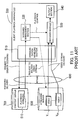
Fig. 11 is a view showing the rough structure of a
conventional streaming video delivery system.
This conventional streaming video delivery system
comprises a client (playback apparatus) 500, a network 600,
a content server 700, and a streaming server 800.
The playback apparatus 500 includes a communication
handling section 510, a scenario management section 520, a
decoder module 530 including a streaming buffer (not
shown) and a decoder (not shown), and an output section
540.
In Fig. 11, the flow of data and the flow of a
control signal are shown by solid and dotted lines
respectively.
A playback scenario S10 stored in the content
server 700 is sent to the communication handling section
510 in the playback apparatus 500 via the network 600 in
accordance with a request to deliver a scenario. The order
in which video sources Vm (m=1,..., M) are played back and
the like are described in the playback scenario S10, which
corresponds to, for example, an ASX file based on the
Windows Media Technology developed by Microsoft
Corporation for processing media. The scenario management
section 520 informs the streaming server 800 of a
streaming video delivery request in accordance with the
order of video playback described in the playback scenario
S10. After being stored temporarily in the streaming
buffer (not shown) in the decoder module 530 used for
performing stable video playback by alleviating the
instability of the network 600 as a bit stream
corresponding to, for example, several seconds to several
tens of seconds, the video source Vm delivered from the
streaming server 800 are processed in order of delivery by
the decoder (not shown), are outputted from the output
section 540, and are displayed on a display device or the
like.
When it is time to switch the video source Vm
described in the playback scenario S10, the scenario
management section 520 exerts control over the decoder
module 530 to terminate playback. As a result, the decoder
module 530 performs a termination process, such as erasing
data stored in the streaming buffer (not shown) and
stopping the decoder. After the termination process being
completed, the scenario management section 520 makes a
request to the streaming server 800 for streaming delivery
of the next video source Vm and gives the decoder module
530 instructions to begin playback.
From the viewpoint of a time axis, the state of
this playback by the decoder module 530 is as follows.
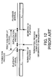
Fig. 12 is a view for describing the operation of a
decoder module performed at the time of continuously
playing back a plurality of video sources by a
conventional method.
When the video sources V1 and V2 are continuously
played back, a termination process is performed first
after the playback of the video source V1 being completed,
then an initialization process including communicating
with the streaming server 800 and buffering a bit stream
is performed, and then the playback of the video source V2
is begun.
By the way, to repeatedly play back a video source
from a specified position, an information playback
apparatus for seamlessly displaying images without harming
the continuity of an animation is disclosed (for example,
see Japanese Unexamined Patent Publication No. 2001-203977,
paragraph numbers [0017]-[0040] and Fig. 1).
The information playback apparatus disclosed in
Japanese Unexamined Patent Publication No. 2001-203977
includes two decoders. One decoder plays back a video
source. The other decoder plays back the video source
which has repeatedly been played back, and puts it into a
pause state. When instructions to repeatedly play back are
given, the decoder which outputs an image will be changed.
This enables a continuous display of a video source.
With the conventional playback apparatus, however,
time taken to perform the termination process and
initialization process as shown in Fig. 12 corresponds to
a non-display interval where a video image will not be
outputted. That is to say, a video cannot be continuously
played back.
Time taken to perform buffering included in the
initialization process has been shortened significantly by
improving a delivery system, but it is difficult to reduce
other factors in the time lag.
Moreover, with the information playback apparatus
disclosed in Japanese Unexamined Patent Publication No.
2001-203977, a plurality of decoders are used for
continuously playing back a video source from the position
from which repeated playback is specified. However, the
position from which repeated playback is performed is
determined on the basis of designation by a user. That is
to say, this information playback apparatus cannot realize
the automatic continuous playback of a plurality of video
sources on the basis of a playback scenario inputted.
SUMMARY OF THE INVENTION
The present invention was made under the background
circumstances as described above. An object of the present
invention is to provide a playback apparatus which can
continuously play back a plurality of streaming videos
without non-display time.
Another object of the present invention is to
provide a playback method by which a plurality of
streaming videos can be continuously played back without
non-display time.
In order to achieve the above first object, a
playback apparatus for receiving and playing back a
plurality of pieces of video information delivered via a
network is provided. This playback apparatus comprises a
plurality of decoder modules for decoding the plurality of
pieces of video information, a scenario management section
for reading a playback scenario where playback information
regarding the plurality of pieces of video information is
described, for determining a playback schedule according
to the playback information, and for exercising
distribution of the plurality of pieces of video
information among the plurality of decoder modules and
switching control over output from the plurality of
decoder modules, an output switching section for switching
output from the plurality of decoder modules under the
switching control, a communication handling section for
making a request via the network to deliver the playback
scenario, receiving the playback scenario via the network,
making a request via the network to deliver the plurality
of pieces of video information, and receiving the
plurality of pieces of video information via the network,
and an output section for outputting the plurality of
pieces of video information.
In order to achieve the above second object, a
playback method for receiving and playing back a plurality
of pieces of video information delivered via a network is
provided. This playback method comprises the steps of
reading a playback scenario where playback information
regarding the plurality of pieces of video information is
described, determining a playback schedule according to
the playback information, and exercising, in accordance
with the playback schedule, distribution of the plurality
of pieces of video information among a plurality of
decoder modules and switching control over output from the
plurality of decoder modules.
The above and other objects, features and
advantages of the present invention will become apparent
from the following description when taken in conjunction
with the accompanying drawings which illustrate preferred
embodiments of the present invention by way of example.
BRIEF DESCRIPTION OF THE DRAWINGS
Fig. 1 is a view for describing the principles
underlying a playback apparatus according to the present
invention and the structure thereof.
Fig. 2 is a view for describing data structure
indicative of a video source.
Fig. 3 is a flow chart showing a method for
distributing M video sources among N decoder modules.
Fig. 4 is a view showing an example in which the
distribution method shown in Fig. 3 is applied.
Fig. 5 is a view for describing the timing with
which a decoder module is controlled.
Fig. 6 is a view for describing the timing with
which a decoder module is controlled in the case of a
delay in initialization exceeding a margin.
Fig. 7 is a view showing the structure of a
playback apparatus according to an embodiment of the
present invention.
Fig. 8 is the state transition diagram of a
synchronization controller.
Fig. 9 is the state transition diagram of a video
player.
Fig. 10 is a flow chart showing a method for
distributing M video sources among N decoder modules in
dynamic scheduling.
Fig. 11 is a view showing the rough structure of a
conventional streaming video delivery system.
Fig. 12 is a view for describing the operation of a
decoder module performed at the time of continuously
playing back a plurality of video sources by a
conventional method.
DESCRIPTION OF THE PREFERRED EMBODIMENT
An embodiment of the present invention will now be
described with reference to the drawings.
Fig. 1 is a view for describing the principles
underlying a playback apparatus according to the present
invention and the structure thereof.
A playback apparatus 10 according to the present
invention is connected via a network 20, such as the
Internet, to a content server 30 which manages a playback
scenario S1 and a streaming server 40 which manages a
plurality of video sources Vm (m=1, ..., M).
In Fig. 1, the flow of data and the flow of a
control signal are shown by solid and dotted lines
respectively.
The playback apparatus 10 comprises decoder modules
Dn (n=1, ..., N), a scenario management section 11, a
changeover switch 12, a communication handling section 13,
and an output section 14.
Each of the decoder modules Dn includes a streaming
buffer (not shown) and a decoder (not shown) and decodes
an encoded streaming video.
The scenario management section 11 reads the
playback scenario S1 where playback information regarding
the plurality of video sources Vm is described, determines
a playback schedule according to the playback information,
and exercises distribution of the video sources Vm among
the decoder modules Dn and switching control over output
from the decoder modules Dn.
The changeover switch 12 is used for switching
output from the decoder modules Dn under switching control
exercised by the scenario management section 11.
The communication handling section 13 makes a
request via the network 20 to deliver the playback
scenario S1, receives the playback scenario S1 via the
network 20, makes a request via the network 20 to deliver
the video sources Vm, and receives the video sources Vm via
the network 20.
The output section 14 outputs the video sources Vm
decoded by the decoder module Dn selected by the changeover
switch 12 to a display (not shown) or the like.
The operation of the playback apparatus 10 will now
be described.
When the playback apparatus 10 makes a request to
deliver the playback scenario S1, the playback scenario S1
stored in the content server 30 is inputted to the
communication handling section 13 via the network 20 and
is downloaded into the scenario management section 11. The
scenario management section 11 reads and analyzes the
playback scenario S1, extracts the video sources Vm to be
displayed in succession in a content and the time when the
video sources Vm are to be displayed from playback
information described in the playback scenario S1, and
rearranges them in order of display time. Then the
scenario management section 11 determines the distribution
of the video sources Vm among the plurality of decoder
modules Dn, a playback schedule, and a schedule of
switching by the changeover switch 12 on the basis of a
time lag (ΔS) in displaying the video sources Vm managed by
the streaming server 40 and time (ΔE) taken to perform a
termination process.
Table 1 shows data structure indicative of a video
source.
| URL | place where video source itself is stored |
| start | playback starting time indicated by general time |
| local_start | playback starting time indicated by video time |
| duration | video playback time |
| decoder | ID of decoder to which video source is distributed |
As shown in Table 1, data structure indicative of
the video source Vm includes "URL (uniform resource
locator)" which indicates a place where the video source Vm
itself is stored, "start" which indicates playback
starting time by general time (scenario time), being the
time when a user is watching or listening, "local_start"
which indicates playback starting time by video time,
being time in the video source Vm, "duration" which
indicates video playback time, and "decoder" which
indicates the ID of a decoder to which the video source Vm
is distributed. "URL," "start," "local_start," and
"duration" are described in a playback scenario and
"decoder" is added to the data structure by the scenario
management section 11 by the method described later.
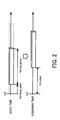
Fig. 2 is a view for describing data structure
indicative of a video source.
As shown in Fig. 2, when a user watches, a playback
interval in the video source Vm specified by
"Vm.local_start" and "Vm.duration" by the video time will
be incorporated into time specified by "Vm.start" by the
scenario time. It is assumed that the M video sources Vm
have been sorted in ascending order of "start".
At this time the plurality of video sources Vm will
be distributed among the decoder modules Dn in the
following way.
Fig. 3 is a flow chart showing a method for
distributing M video sources among N decoder modules.
Descriptions will now be given with video source
IDs as m (m=1,..., M) and with decoder IDs as n (n=1,..., N)
When the scenario management section 11 reads the
playback scenario S1, the scenario management section 11
sets the initial value of m, being the ID of distributed
video sources Vm. With static distribution in which all of
the video sources Vm are distributed before a content being
played back, the initial value of m is set to 1. With
dynamic distribution in which a playback scenario is added
with the playback of a content or according to
circumstances, the initial value of m is set to the
smallest one of the IDs of video sources which are not yet
distributed (step S1).
Next, the video source Vm, which has already been
distributed and which meets the condition (condition 1) of
"Vm'.URL=Vm.URL" and "Vm'.start+Vm'.duration=Vm.start" is
searched for. That is to say, the video source Vm' which
is stored in the same place as the video source Vm and the
ending time of which matches the playback starting time of
the video source Vm is searched for. If there is video
source Vm' which meets the above condition, then step S3
will be performed. If there is no video source Vm, which
meets the above condition, then step S4 will be performed
(step S2).
If the condition shown in step S2 is met, then the
same decoder module that was used to play back the video
source Vm' should be used to decode the video source Vm.
Therefore, "Vm.decoder←Vm'.decoder" is given and the ID of
a decoder used to decode the video source Vm is the same as
the ID of the decoder used to decode the video source Vm,
(step S3).
If there is no video source Vm' which meets the
condition shown in step S2, then decoder module Dn which is
not being used at time "Vm.start" is extracted. It is
assumed that the last ending time of the decoder module Dn
is T. Decoder module Dn which meets the condition of
"Vm.start-ΔS>T+ΔE" is searched for. That is to say,
decoder module Dn which meets the condition that the
playback starting time "Vm.start" of the video source Vm
minus time "ΔS" taken to perform an initialization process
is greater than its last ending time T plus time ΔE taken
to perform a termination process (the margin described
later is taken into consideration) is searched for. If
there is one decoder module Dn which meets the above
condition, then step S5 will be performed. If there are a
plurality of decoder modules Dn which meet the above
condition, then step S6 will be performed. If there is no
decoder module Dn which meets the above condition, then
step S7 will be performed (step S4). If there is only one
decoder module Dn which meets the above condition, it is
used for playback. That is to say, "Vm.decoder←n" is given
(step S5). If there are a plurality of decoder modules Dn
which meet the above condition, "Vm.decoder" is set to the
decoder ID of one of them that terminates playback first
(step S6). If there is no decoder module Dn which meets
the above condition, "Vm.decoder" is set to the decoder ID
of one of all decoder modules Dn that terminates playback
first (step S7). When the setting of "Vm.decoder" in any
of steps S5 through S7 is completed, m, being a video
source ID, is incremented by 1 (step S8). If m>M, that is
to say, if the distributing of all video sources Vm is
completed, then the process is terminated. If m≤M, then
the process will be repeated from step S2 (step S9).
By doing so, a plurality of video sources Vm can be
distributed among a plurality of decoder modules Dn.
Fig. 4 is a view showing an example in which the
distribution method shown in Fig. 3 is applied.
In this example, video sources V8 through V12 are
distributed among a plurality of decoder modules D1 through
D3.
It is assumed that video sources Vm have been
extracted and have been rearranged in order of display
time in accordance with the playback scenario S1
downloaded.
It is assumed that the video source V11 having the
video source ID of 11 is distributed. If there is no video
source Vm' which meets the condition of "Vm'.URL=V11.URL"
and "Vm'.start+Vm'.duration=V11.start" in step S2 shown in
Fig. 3, then step S4 will be performed. In this case, of
decoder modules Dn which are not being used, only the
decoder module D1 having the decoder ID of 1 meets the
condition of "V11.start-ΔS>T+ΔE". Therefore, step S5 will
be performed and the video source V11 is distributed to the
decoder module D1 to decode.
The scenario management section 11 controls the
changeover switch 12 in accordance with a switching
schedule shown at the bottom of Fig. 4 to switch output
from the decoder modules D1 through D3 which decode the
video sources V8 through V12 distributed in this way. This
enables a seamless video display.
Fig. 5 is a view for describing the timing with
which a decoder module is controlled.
For example, with the decoder module D1 shown in
Fig. 4, an initialization process for the next video
source V11 is begun some time after a termination process
for the video source V8 is completed. As shown in Fig. 5,
however, when a termination process for the video source V8
is completed and the decoder module D1 becomes reusable, an
initialization process for the next video source V11 will
actually be begun.
The other decoder modules Dn operate in the same
way.
If the rules for distributing the video sources Vm
are followed, they should go into a state in which they
can be played back by the time when playback is begun.
However, initialization time includes indefinite factors,
such as the occurrence of a network delay, so there is no
guarantee that the video sources Vm will go into a state in
which they can be played back by the time when playback is
begun. Accordingly, when a plurality of decoder modules Dn
can be used, the video sources Vm are distributed to
decoder modules Dn which have not been used for a longer
time to allow for a margin against a delay in
initialization.
Fig. 6 is a view for describing the timing with
which a decoder module is controlled in the case of a
delay in initialization exceeding a margin.
If a delay in initialization exceeds a margin
allowed for in advance, that is to say, if initialization
is not completed by the time when playback is begun, the
subsequent processes will be performed by delaying the
entire schedule time for the time corresponding to a delay
in beginning playback. If such a delay occurs, the
subsequent video sources may be redistributed.
A concrete embodiment of the present invention will
now be described.
Fig. 7 is a view showing the structure of a
playback apparatus according to an embodiment of the
present invention.
A playback apparatus 100 according to an embodiment
of the present invention is connected to a content server
200 including a scenario server 210 and a streaming server
220.
The scenario server 210 stores a playback scenario
in which information included in the data structure
indicative of the video sources Vm shown in Table 1,
excluding "decoder," has been described in the CSV format,
the XML format, or the like.
Table 2 shows an example of a playback scenario
described in the CSV format.
One line indicates one video source Vm. Pieces of
information indicative of "start," "local_start,"
"duration," and "URL" are described in that order in
seconds and are separated by commas.
The streaming server 220 stores various video
contents. An existing product, such as RealServer
(trademark of the RealNetworks Inc.) or Windows Media
Server (trademark of the Microsoft Corporation), will be
used for performing streaming delivery at need. A
plurality of servers will be used depending on a playback
scenario.
The playback apparatus 100 comprises a user
interface 110, a whole control section 120, a scenario
parser 130, a synchronization controller 140, a scheduler
150, a video player 160, and a display section 170.
The playback apparatus 100 may be a personal
computer or dedicated hardware. If the playback apparatus
100 is a personal computer, then the whole or part of the
user interface 110, the whole control section 120, the
scenario parser 130, the synchronization controller 140,
the scheduler 150, and the video player 160 in the
playback apparatus 100 may be described in a downloadable,
executable language, such as Java or JavaScript, to
download and execute them as each module before
downloading a scenario. If the playback apparatus 100 is
dedicated hardware, then they will be realized as hardware
modules.
The scenario server 210 and streaming server 220
shown in Fig. 7 correspond to the content server 30 and
streaming server 40, respectively, shown in Fig. 1. In Fig.
7, the scenario server 210 and streaming server 220 are
united into the content server 200. The network 20 shown
in Fig. 1 is omitted in Fig. 7.
In the playback apparatus 100 shown in Fig. 7, the
user interface 110, the whole control section 120, part of
the function of the scenario parser 130, the
synchronization controller 140, and the scheduler 150
correspond to the scenario management section 11 shown in
Fig. 1. Part of the function of the scenario parser 130
corresponds to the communication handling section 13 shown
in Fig. 1. This communication handling section 13 is
omitted in Fig. 7. In addition, the video player 160 and
the display section 170 correspond to the decoder module Dn
and the output section 14, respectively.
The user interface 110 enables a user to give
instructions to specify a playback scenario to be played
back (input URL), instructions to play back a playback
scenario, instructions to stop or pause the playback of a
playback scenario, or the like. For example, a keyboard, a
switch, or a mouse (not shown) will be connected to the
user interface 110.
The whole control section 120 is a module for
converting instructions from a user inputted by the user
interface 110 to operation instructions to each module.
When instructions to read a playback scenario are
given, the scenario parser 130 communicates with the
scenario server 210, downloads the playback scenario, and
converts it to an internal format. For example, an array
having the data structure indicative of the video sources
Vm (m=1,..., M) shown in the above Table 1 can be used as an
internal format for a playback scenario. When the scenario
parser 130 converts a playback scenario to an internal
format, the scenario parser 130 also sorts data in
ascending order of "start," being playback starting time
by the general time.
The synchronization controller 140 sets data
regarding a plurality of video sources Vm shown in, for
example, Table 1 (excluding "decoder") which is inputted
via the whole control section 120 and which has been
sorted in ascending order, and controls the operation and
output of the video player 160 in accordance with a
playback schedule determined by the scheduler 150.
Furthermore, the synchronization controller 140 controls
the operation of the video player 160 in accordance with
instructions from the whole control section 120 to play
back a playback scenario or to stop or pause the playback
of a playback scenario.
On the basis of data regarding a plurality of video
sources Vm set in the synchronization controller 140, the
scheduler 150 determines by the distribution method
described in Fig. 3 which video player 160 plays back each
of the plurality of video sources Vm.
There are a plurality of video players 160, which
corresponds to the fact that a plurality of streaming
servers 220 may be used. Under the control of the
synchronization controller 140, each video player 160
temporarily stores video sources Vm inputted via the
network (not shown) in a streaming buffer (not shown) as
bit streams corresponding to several seconds to several
tens of seconds, decodes them in order of store, and
outputs them to the display section 170. By doing so, the
instability of the network (not shown) will be alleviated
and stable video playback will be performed.
The display section 170 displays video sources Vm
decoded by the video players 160 on a display (not shown)
or the like.
In this embodiment, the same effect that can be
obtained by the use of the changeover switch 12 explicitly
shown in Fig. 1 is realized by controlling the
visibility/invisibility of all the video players 160.
Output images are displayed one over another by the
display section 170. However, a playback scenario has been
set so that one video player 160 will be visible.
Therefore, only one video will always be displayed.
The operation of the playback apparatus 100 will
now be described.
When the URL of a playback scenario is inputted
from the user interface 110, the whole control section 120
gives the scenario parser 130 instructions to read the
playback scenario. The scenario parser 130 downloads the
playback scenario from the scenario server 210, converts
it to an internal format, and sorts a plurality of video
sources Vm in ascending order of playback starting time by
the general time. Data indicative of the plurality of
video sources Vm read and sorted is set as an object of
playback by the synchronization controller 140 via the
whole control section 120.
The operation of the synchronization controller 140
will now be described.
Fig. 8 is the state transition diagram of the
synchronization controller.
Each of symbols T1 through T4 indicates a state.
When the synchronization controller 140 is in an
initial state (state T1) and a playback scenario is read,
data indicative of video sources Vm is set as an object of
playback and the synchronization controller 140 makes the
transition to a state T2. When the synchronization
controller 140 is in the state T2, the playback of the
playback scenario is in a stopped state. At this time a
periodic start turns off and the scenario time goes into
an initial state (Ts=0.0 sec). When the synchronization
controller 140 is in the state T2 and the whole control
section 120 gives instructions to play back the playback
scenario, the synchronization controller 140 is started
periodically every minute period Δt (several milliseconds,
for example) and the playback scenario goes into a played
back state (state T3). Therefore, the video players 160
begin to play back and output in accordance with a
schedule determined by the scheduler 150. When the whole
control section 120 gives instructions to pause the
playback of the playback scenario, the periodic start is
stopped and the advance of the scenario time stops (state
T4). When the whole control section 120 gives instructions
to stop the playback of the playback scenario, the
synchronization controller 140 makes the transition to the
state T2. Accordingly, the periodic start is stopped and
the scenario time is returned to the initial state (Ts=0.0
sec). When the playback of the playback scenario is in a
paused state (state T4) and the whole control section 120
gives instructions to play back the playback scenario, the
synchronization controller 140 makes the transition to the
state T3. When the playback of the playback scenario is in
a paused state (state T4) and the whole control section
120 gives instructions to stop the playback of the
playback scenario, the synchronization controller 140
makes the transition to the state T2.
The playback state (state T3) will now be described
in detail.
As stated above, the synchronization controller 140
is started periodically when a playback scenario is in a
playback state. When the synchronization controller 140 is
started periodically, time which elapsed after the
beginning of the playback of the playback scenario is
reflected in scenario time Ts. By comparing the scenario
time Ts and an array of video sources Vm which make up the
playback scenario, the operation of the video player 160
indicated by "Vm.decoder" is determined on the basis of the
following conditions.
If "Vm-1.start+Vm-1.duration≤Ts<Vm.start" (condition
2), that is to say, if the playback of the video source Vm-1
has been completed, the playback of the next video source
Vm is not yet performed, and the video player is in a
stopped state, then "Vm.URL" will be set to perform
prefetch.
If "Vm.start≤Ts<Vm.start+Vm.duration" (condition 3),
that is to say, if the video source Vm-1 is being played
back, then playback will be performed for
"Vm.local_start+Vm.start-Ts" seconds by video local time.
If "Vm.start+Vm.duration≤Ts" (condition 4), that is
to say, if the video source Vm is played back, then the
synchronization controller 140 will make the transition to
the state T2 (the playback of the playback scenario is in
a stopped state).
If m=1, then condition 2 becomes "Ts<Vm.start".
It is assumed that the video source Vm meets
condition 4. If there is video source Vm+1 which meets
condition 1 described in step S2 shown in Fig. 3, then the
playback of the next Vm+1 under condition 3 will precede.
That is to say, video sources Vm having the same URL in
"Vm.decoder(=Vm+1.decoder)" will be continuously played back.
Though the transition to a prefetch state is made
under condition 2, condition 3 may be met before the
transition to a prefetch state being completed. In this
case, playback cannot be begun. Therefore, until the
transition to a prefetch state is completed, Ts will not be
increased from "Ts=Vm.start". As soon as the transition to
a prefetch state is completed, the transition to a
playback state will be made and an increase of Ts will be
resumed.
The operation of the video players 160 will now be
described.
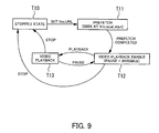
Fig. 9 is the state transition diagram of the video
players.
By exercising control, such as playback, pausing
playback, stopping playback, or setting a URL, over the
video player 160 under the above condition 2, 3, or 4, it
makes state transition.
When the video player 160 is in a stopped state
(state T10) and "Vm.URL" is set, the video player 160 makes
the transition to a prefetch state (state T11). In this
case, the video player 160 will seek at "Vm.local_start,"
being playback starting time by the video time. When
prefetch is completed, the video player 160 makes the
transition to a video playback enable state (state T12).
At this time the video player 160 is in a paused state and
does not provide output to the display section 170. When
playback control is exercised over the video player 160 in
a video playback enable state, the video player 160 makes
the transition to a video playback state (state T13). When
stop control is exercised over the video player 160 in a
video playback enable state, the video player 160 makes
the transition to a stopped state. The video player 160
outputs a video it decoded to the display section 170.
When stop control is exercised over the video player 160
in a video playback state, the video player 160 makes the
transition to a stopped state. When pause control is
exercised over the video player 160 in a video playback
state, the video player 160 makes the transition to a
video playback enable state.
Moreover, the visibility/invisibility (or
output/non-output) of a video played back by the video
player 160 can be switched. When the video player 160 is
in a video playback state (state T13), a video played back
by the video player 160 is visible. When the video player
160 is in another state, a video played back by the video
player 160 is invisible.
Dynamic scheduling will now be described.
A case where static scheduling is performed at the
time of a playback scenario being set in the
synchronization controller 140 has been described. With
static scheduling, fixed values are used as the necessary
coefficients ΔS and ΔE and individual video sources Vm are
distributed in advance among the video players 160.
However, these values will vary according to network
conditions, loads on the streaming servers 220 to which
the video players 160 are connected, and the like.
With dynamic scheduling, the video players 160 feed
back values actually determined in processes performed
theretofore by them to the synchronization controller 140
and these values are reflected in the subsequent
scheduling performed by the scheduler 150. As a result,
continuous video playback can be performed more flexibly.
The operation of the playback apparatus 100 at
dynamic scheduling time will now be described.
When a playback scenario is set, the
synchronization controller 140 initially operates the same,
whether at static scheduling time or at dynamic scheduling
time.
The synchronization controller 140 has a table
which stores ΔS and ΔE for each of the streaming servers
220 included in URLs set in the video players 160.
Table 3 is an example of a coefficient store table.
| server name | ΔS | ΔE |
| foo01.com | 15.0sec | 1.0sec |
| foo02.com | 10.0sec | 1.5sec |
| . | . | . |
| . | . | . |
| . | . | . |
The fixed values used in the static scheduling will
be used as the initial values of ΔS and ΔE in this table.
For example, each time the synchronization controller 140
gives the video player 160 instructions to play back, the
synchronization controller 140 inquires the measured value
of time from a URL being set to the video player 160
making the transition to a video playback enable state and
the measured value of time from instructions to stop being
given to the video player 160 making the transition to a
stopped state and updates the values of ΔS and ΔE
corresponding to the appropriate server name by the use of
the newest measured values. To access each coefficient in
the coefficient store table, the forms of, for example,
ΔS[server name] and ΔE[server name] will be used.
When the values of ΔS and ΔE are updated and values
in the coefficient store table change, rescheduling will
be performed. Video sources "Vm*.URL" which are not yet
set in the video players 160 are to be rescheduled. That
is to say, the video sources Vm*, Vm*+1,..., VM will be
rescheduled and scheduling will be performed with m* as
the initial value of m.
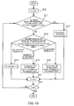
Fig. 10 is a flow chart showing a method for
distributing M video sources among N decoder modules in
dynamic scheduling.
The flow chart shown in Fig. 10 differs from that
shown in Fig. 3 only in steps S10 and S13.
As stated above, video sources "Vm*.URL" which are
not yet set in the video players 160 are to be rescheduled
in step S10. That is to say, the video sources Vm*, Vm*+1,...,
VM will be rescheduled, so the initial value of m will be
set to m*.
In step S13, decoder module Dn which is not being
used is searched for. This is the same with step S4 in Fig.
3. In this case, however, ΔS and ΔE are set according to
the state of the streaming servers 220 at access time by
the use of the condition of "Vm.start-ΔS[server name
included in Vm.URL]>T+ΔE[preceding server name]".
The other processes are the same as those in the
distribution method shown in Fig. 3, so descriptions of
them will be omitted.
As described above, by determining ΔS and ΔE on the
basis of measured values obtained in processes performed
before communication with the streaming servers 220 and by
feeding back them to the synchronization controller 140,
continuous playback in which the newest streaming state of
the appropriate server is reflected can be realized.
Static scheduling may be performed by the use of a
coefficient store table in which the values of the
coefficients for each server are fixed. In this case,
scheduling is realized by using the flow chart in Fig. 10
on which m* is set to 1. Values measured for each
streaming server 220 should be used as the fixed
coefficients in the coefficient store table. In addition,
values in this fixed coefficient store table may be used
as initial values in a coefficient store table at dynamic
scheduling time.
In the above descriptions it has been assumed that
delivery of the entire playback scenario was completed
before the playback of the playback scenario. However, the
playback scenario can be considered as a set of a
plurality of scenario Sp (p=1, 2,...). In this case, even
before the entire playback scenario is delivered, partial
scenarios Sp delivered in order can be executed.
The scenario server 210 manages the playback
scenario as a set of partial scenarios Sp (p=1, 2 , ...).
Partial scenarios Sp may be stored in advance or may be
generated in order at calling time.
When the whole control section 120 gives the
scenario parser 130 instructions to read the playback
scenario, the scenario parser 130 begins to read the
playback scenario and obtains a partial scenario Sp. The
partial scenario Sp is sent to the synchronization
controller 140, is distributed to a video decoder by
static or dynamic scheduling, and is played back.
The whole control section 120 gives the scenario
parser 130 instructions every certain period of time to
read the partial scenario Sp subsequent to the one which
the scenario parser 130 has already received. If there is
no partial scenario Sp read, then there will be nothing to
be changed. If there is a partial scenario Sp read, then
the whole control section 120 sets the partial scenario Sp
in the synchronization controller 140. The synchronization
controller 140 combines partial scenarios Sp which have
already been set therein and the partial scenario Sp newly
set, performs dynamic scheduling on the combined partial
scenarios Sp, and continues its playback. A scheduling
method used in this case is the same as that shown in Fig.
10.
Partial scenarios Sp may be delivered from the
scenario server 210 in push mode. In this case, partial
scenarios Sp delivered in push mode are parsed by the
scenario parser 130 and are processed in the same way that
was described above.
The above functions can be realized with a computer.
In this case, a program in which the contents of the
functions the playback apparatus 100 should have are
described is provided. By executing this program on a
computer, the above functions are realized on the computer.
This program can be recorded on a computer readable record
medium. A computer readable record medium can be a
magnetic recording device, an optical disk, a magneto-optical
recording medium, a semiconductor memory, or the
like. A magnetic recording device can be a hard disk drive
(HDD), a flexible disk (FD), a magnetic tape, or the like.
An optical disk can be a digital versatile disc (DVD), a
digital versatile disc random access memory (DVD-RAM), a
compact disc read only memory (CD-ROM), a compact disc
recordable (CD-R)/rewritable (CD-RW), or the like. A
magneto-optical recording medium can be a magneto-optical
disc (MO) or the like.
To place the program on the market, portable record
media, such as DVDs or CD-ROMs, on which it is recorded
are sold. Alternatively, the program is stored in advance
on a hard disk in a server computer and is transferred to
another computer via a network.
When a computer executes this program, it will
store the program, which is recorded on a portable record
medium or which is transferred from a server computer, on,
for example, its hard disk. Then it reads the program from
its hard disk and performs processes in compliance with
the program. A computer can also read the program directly
from a portable record medium and perform processes in
compliance with the program. Furthermore, each time the
program is transferred from a server computer, a computer
can perform processes in turn in compliance with the
program it received.
As has been described in the foregoing, in the
present invention, a plurality of video sources delivered
via a network can continuously be played back in the order
which is described in a playback scenario without non-display
time at each video joint.
Furthermore, scheduling for distributing a
plurality of video sources among a plurality of decoder
modules is performed, so flexible continuous playback can
be realized without describing a playback schedule in
advance in a playback scenario.
The foregoing is considered as illustrative only of
the principles of the present invention. Further, since
numerous modifications and changes will readily occur to
those skilled in the art, it is not desired to limit the
invention to the exact construction and applications shown
and described, and accordingly, all suitable modifications
and equivalents may be regarded as falling within the
scope of the invention in the appended claims and their
equivalents.