EP1411413A2 - Attachable/detachable keyboard apparatus of portable computer system - Google Patents
Attachable/detachable keyboard apparatus of portable computer system Download PDFInfo
- Publication number
- EP1411413A2 EP1411413A2 EP03006225A EP03006225A EP1411413A2 EP 1411413 A2 EP1411413 A2 EP 1411413A2 EP 03006225 A EP03006225 A EP 03006225A EP 03006225 A EP03006225 A EP 03006225A EP 1411413 A2 EP1411413 A2 EP 1411413A2
- Authority
- EP
- European Patent Office
- Prior art keywords
- keyboard
- case
- connector
- disk
- main body
- Prior art date
- Legal status (The legal status is an assumption and is not a legal conclusion. Google has not performed a legal analysis and makes no representation as to the accuracy of the status listed.)
- Granted
Links
Images





Classifications
-
- G—PHYSICS
- G06—COMPUTING OR CALCULATING; COUNTING
- G06F—ELECTRIC DIGITAL DATA PROCESSING
- G06F1/00—Details not covered by groups G06F3/00 - G06F13/00 and G06F21/00
- G06F1/16—Constructional details or arrangements
- G06F1/1613—Constructional details or arrangements for portable computers
- G06F1/1615—Constructional details or arrangements for portable computers with several enclosures having relative motions, each enclosure supporting at least one I/O or computing function
- G06F1/1616—Constructional details or arrangements for portable computers with several enclosures having relative motions, each enclosure supporting at least one I/O or computing function with folding flat displays, e.g. laptop computers or notebooks having a clamshell configuration, with body parts pivoting to an open position around an axis parallel to the plane they define in closed position
- G06F1/162—Constructional details or arrangements for portable computers with several enclosures having relative motions, each enclosure supporting at least one I/O or computing function with folding flat displays, e.g. laptop computers or notebooks having a clamshell configuration, with body parts pivoting to an open position around an axis parallel to the plane they define in closed position changing, e.g. reversing, the face orientation of the screen with a two degrees of freedom mechanism, e.g. for folding into tablet PC like position or orienting towards the direction opposite to the user to show to a second user
-
- G—PHYSICS
- G06—COMPUTING OR CALCULATING; COUNTING
- G06F—ELECTRIC DIGITAL DATA PROCESSING
- G06F1/00—Details not covered by groups G06F3/00 - G06F13/00 and G06F21/00
- G06F1/16—Constructional details or arrangements
-
- G—PHYSICS
- G06—COMPUTING OR CALCULATING; COUNTING
- G06F—ELECTRIC DIGITAL DATA PROCESSING
- G06F1/00—Details not covered by groups G06F3/00 - G06F13/00 and G06F21/00
- G06F1/16—Constructional details or arrangements
- G06F1/1613—Constructional details or arrangements for portable computers
- G06F1/1632—External expansion units, e.g. docking stations
-
- G—PHYSICS
- G06—COMPUTING OR CALCULATING; COUNTING
- G06F—ELECTRIC DIGITAL DATA PROCESSING
- G06F1/00—Details not covered by groups G06F3/00 - G06F13/00 and G06F21/00
- G06F1/16—Constructional details or arrangements
- G06F1/1613—Constructional details or arrangements for portable computers
- G06F1/1633—Constructional details or arrangements of portable computers not specific to the type of enclosures covered by groups G06F1/1615 - G06F1/1626
- G06F1/1662—Details related to the integrated keyboard
- G06F1/1669—Detachable keyboards
-
- G—PHYSICS
- G06—COMPUTING OR CALCULATING; COUNTING
- G06F—ELECTRIC DIGITAL DATA PROCESSING
- G06F1/00—Details not covered by groups G06F3/00 - G06F13/00 and G06F21/00
- G06F1/16—Constructional details or arrangements
- G06F1/1613—Constructional details or arrangements for portable computers
- G06F1/1633—Constructional details or arrangements of portable computers not specific to the type of enclosures covered by groups G06F1/1615 - G06F1/1626
- G06F1/1675—Miscellaneous details related to the relative movement between the different enclosures or enclosure parts
- G06F1/1679—Miscellaneous details related to the relative movement between the different enclosures or enclosure parts for locking or maintaining the movable parts of the enclosure in a fixed position, e.g. latching mechanism at the edge of the display in a laptop or for the screen protective cover of a PDA
-
- Y—GENERAL TAGGING OF NEW TECHNOLOGICAL DEVELOPMENTS; GENERAL TAGGING OF CROSS-SECTIONAL TECHNOLOGIES SPANNING OVER SEVERAL SECTIONS OF THE IPC; TECHNICAL SUBJECTS COVERED BY FORMER USPC CROSS-REFERENCE ART COLLECTIONS [XRACs] AND DIGESTS
- Y10—TECHNICAL SUBJECTS COVERED BY FORMER USPC
- Y10S—TECHNICAL SUBJECTS COVERED BY FORMER USPC CROSS-REFERENCE ART COLLECTIONS [XRACs] AND DIGESTS
- Y10S345/00—Computer graphics processing and selective visual display systems
- Y10S345/905—Display device with housing structure
Definitions
- the present invention relates to a portable computer system.
- PC personal computer
- PDA personal digital assistant
- a related art notebook PC is one main body including a system with keyboard to input text or data attached to the main body.
- the notebook PC can be carried anywhere, its weight is rather heavy and it is occasionally inconvenient to use.
- a floppy disk drive (FDD) or an optical disk drive was separated from the main body, and connected to the main body only if necessary for use.
- PDAs personal digital assistances
- a stylus pen to tap a virtual keyboard on a display or actually write on the display.
- tapping the virtual keyboard on an extremely small screen is difficult.
- a web pad recognizes the characters as a text. In doing so, however, the web pad makes a number of errors (e.g., character recognition error). Also, it is not easy to write document while the web pad is not being steadily supported or is moving.
- the PDA recognizes input signals into the keyboard.
- U.S. Patent No. 6,108,200 discloses a method for directly connecting/detaching a separate keyboard system to/from PDA.
- Figs. 1a and 1b diagrammatically illustrate a prior art keyboard apparatus looks like before and after a web pad is installed thereon.
- the keyboard apparatus includes an interface 812 mounted with a connector for connecting a web pad to upper portion of a keypad 811.
- the interface 812 is one body with a keypad cover portion 813. Normally, the cover 813 rotates around a hinge that is installed on one end of the cover 813.
- the web pad is connected to the keypad 811 by inserting into the interface 812, and a user can input data, e.g., characters, by using the keypad 811.
- the prior art keyboard apparatus has various problems. Since the keyboard is turned on all the time to have the keypad 812 automatically converted to a mode through which the user can input characters whenever the web pad is connected to the interface 812, the keyboard is on even when the user does not input any data, which consumes much power. Further, if the user puts the cover portion 813 on the keyboard after the web pad is installed into the keyboard, the user cannot use the web pad. Also, the cover portion 813 can rotate only to cover the keypad 811.
- notebook PCs use two opening/closing buttons on a cover that includes a display to secure the cover in a closed position to the main or system body.
- opening/closing apparatus do not work together, and a user has to use fingers of both hands at the same time in order to operate the buttons.
- An object of the invention is to solve at least the above problems and/or disadvantages and to provide at least the advantages described hereinafter.
- Another object of the present invention is to provide a keyboard apparatus that can attach to the main body of a system being used as web pad to selectively use the keyboard to input text and data.
- Another object of the present invention is to provide a keyboard apparatus that reduces power consumption.
- Another object of the present invention is to provide a keyboard apparatus that reduces power consumption by allowing the system to operate as web pad only when closed.
- Another object of the present invention is to provide a keyboard apparatus that reduces power consumption by enabling the keypad in an open position.
- Another object of the present invention to provide a keyboard apparatus detachment apparatus of portable multi-type computer system that moves between a closed position and an open position.
- Another object of the present invention to provide a keyboard apparatus detachment apparatus of portable multi-type computer system that is capable of connecting the keyboard apparatus to the system's main body both backward and forward.
- an attachable/detachable keyboard apparatus of portable multi-type computer system that includes a keyboard case having a front case and a rear case that are connected to each other to enclose a space therebetween; a keypad for inputting data being mounted on of the keyboard case; a rotating member for rotating web pad at a designated angle around the keyboard case installed on the keyboard case; a connector for connecting the key pad to the web pad to transmit signals that are inputted from the key pad to the web pad; and a keyboard connecting projection formed at one side of the rotating member for securing the keyboard to the web pad as the keyboard settles in one side of the web pad.
- a user can input text and data in the system's main body being used as web pad by selectively using the keyboard, and can save power consumption by allowing the system to operate as web pad only while limiting data input through the keyboard is if the keyboard connected to the system's main body.
- a system that includes a keyboard case, an input device exposed in an upper surface of the keyboard case, and a connector mounted on the keyboard case for connection to a portable computer, wherein the connector rotates between a first position and a second position, wherein the keypad is disabled unless the connector is in the second position.
- a keyboard apparatus that includes a keyboard case, an input device exposed in an upper surface of the keyboard case, a connector mounted on the keyboard case for detachable connection to a portable computer, wherein the connector includes a rotational disk that rotates around a fixed point relative to the upper surface of the keyboard case, and a hinge rigidly coupled to the rotational disk displaced a prescribed distanced from the fixed point.
- a portable multi-type computer system that includes a web pad-type computer, a keyboard apparatus that detachably connects to the web pad, wherein the keyboard apparatus includes a keyboard case having a front case and a rear case that are coupled together to enclose a space therebetween, a keypad exposed in an upper surface of the keyboard case, and a keyboard opening/closing apparatus mounted on the keyboard case that selectively rigidly attaches the web pad to the keyboard apparatus, wherein the keypad is disabled unless the keyboard opening/closing apparatus is in an open position.
- Figs. 2a-2b are diagrams showing perspective views of a preferred embodiment of a keyboard apparatus according to the present invention that can be coupled to a main body of a system.
- keyboard apparatus 300 is appropriate for use in a portable multi-system (e.g., web pad function and notebook PC function) computer.
- the keyboard apparatus 300 can be attached to a main body 100 of a system (e.g., web pad), and one can selectively use a keyboard if data or text should be input.
- a system e.g., web pad
- the computer When the computer is used as a web pad, a user can detach the keyboard apparatus from the main body and carry more conveniently.
- the present invention is not intended to be so limited.
- the web pad can be attached in a closed accessible or protected position to a keyboard apparatus.
- Preferred embodiments of an attachable/detachable keyboard apparatus 300 of portable multi-type computer system as shown in Figs. 2a-13b can include a keyboard case 310, a keypad 320 through which a user can input data and a rotating member 330 that enables the keyboard case 310 to rotate around main body 100 of the system, e.g., web pad, at a designated angle and that inverts the system from pen input mode using a stylus 200 to keyboard input mode that uses a keyboard through a rotation operation.
- a connector 343 can couple the key pad 320 to the system's main body 100 for transmitting signals having been input from the key pad 320 to the system's main body 100.
- a keyboard docking projection 360 can secure the keyboard apparatus 300 to the system's main body 100 to protect a display screen as desired or when the key input is not performed for an extended period of time.
- a fixed projection insert hole 313 is preferably formed at one side of the keyboard case 310 for mounting on a docking system or for connecting the system's main body to a connector of a docking system, external expansion apparatus or the like, if necessary while the main body 100 can remain connected to the keyboard. Also, at the other side of the keyboard case 310, there is a plurality of passing grooves 314 that can secure projections for the purpose of making the connection between a cradle, another expansion apparatus, and the main body of the system 100 more secure while reducing or avoiding any interference to web pad (e.g., system) securing projections.
- web pad e.g., system
- the main body of the system 100 preferably has a display at one front surface and a battery cover (not shown) at its opposing rear surface. Except the display and the rear, the other four edges are all sides.
- one side of the main body 100 includes a plurality of keyboard docking projection insert holes (not shown in Figs. 2a-2b) for coupling to the keyboard apparatus 300.
- the male connector 343 and keyboard docking projection 360 can be inserted and fixated with a prescribed movement. More specifically, if a user wants to connect the keyboard 300 to the main body 100 of the system, the user should pass the keyboard docking projection 360 through the keyboard docking projection insert hole, and then lock in a locking projection detaching side preferably at the end of a first frame 155 as shown in Fig. 3.
- a reverse-insertion preventing mechanism such as a reverse-insertion preventing projection 360a nearby the keyboard docking projection 360, and a groove (not shown) at an opposite side of the main body 100, through which the reverse-insertion preventing projection 360a can pass.
- the display is preferably coupled, facing outward from the system's main body 100 while the rear of the main body is not turned to the outside.
- the display surface of the system could be set up to face the outside, or the display surface could face the key board apparatus with the rear of the system 100 facing outward.
- Fig. 2a represents the keyboard apparatus 300 coupled to the main body 100 of the system.
- Fig. 3 is a diagram that shows a sectional perspective view of parts of the keyboard apparatus 300 according to the present invention.
- a type of rotating member 330 can be employed to rotate the system's main body 100 around the keyboard apparatus 300 at a designated angle.
- the rotating member 330 is secured on the rear of a front case 311 for better rotation.
- the rotating member 330 can include an upper rotation guide member 331 disposed at the rear surface of the front case 311, a keyboard disk assembly 332 that rotates along a guide rail 331a formed on the rear surface of the upper rotation guide member 331 and a lower rotation guide member 334 for fastening the upper rotation guide member 331 and the keyboard disk assembly 332 preferably to a boss formed on the rear surface of the front case 311.
- the lower rotation guide member 334 can include a data input mode inverting switch 333 at a certain position of the front surface.
- the guide rail 331a formed on the rear surface of the upper rotation guide member 331 is preferably a projected guide surface with a concentric circular shape.
- the guide rail 331a should allow rotation relative to the guide surface formed on the upper surface of the lower rotation guide member 334 while coming in contact with the guide surface at the same time.
- the boss on the rear surface of the front case 311 can go through a certain position of the upper rotation guide member 331 on which a plurality of through holes 334 is formed to make the upper rotation guide member 331 better supported by the boss.
- Fig. 5 is a diagram that shows an outer appearance of an exemplary keyboard disk assembly and functionally decomposed parts of the exemplary keyboard disk assembly.
- Fig. 6 is a diagram that shows a decomposition of parts of an exemplary hinge assembly.
- the keyboard disk assembly 332 is set up to securely rotate along a guide rail 331a formed on the rear surface of the upper rotation guide member 331.
- the keyboard disk assembly 332 includes a keyboard disk 335 that rotates along a guide rail 331a formed on the rear surface of the upper rotation guide member 331.
- the keyboard disk 335 can include a projection 335a on the rear side that can contact with a data input mode inverting switch 333 along the rotation, a hinge frame 336 being screwed onto the keyboard disk 335, and a hinge assembly 337 that rotates at one side of the hinge frame 336.
- the hinge assembly 337 further can include a first connector cover 338; a second connector cover 339 on an opposite side to the first connector cover 338 and a first and second hinges 340 and 341 disposed between the first connector cover 338 and the second connector cover 339 being fastened (e.g., screwed) at both ends thereof.
- a hinge cover 342 can fasten the first and second hinges 340 and 341 (e.g., with hinged sections 340a, 340b and 341a, 341b) onto the hinge frame 336, and at the same time cover them.
- Fig. 6 shows exemplary internal/external couplings.
- the hinge frame 336 can be screwed down to the upper end of the keyboard disk 335, and the hinge assembly 337 is coupled to the edge of the upper end of the hinge frame 336 in such manner that the hinge assembly 337 may rotate between the keyboard apparatus 300 and the system 100 of the system at a designated angle.
- the first connector cover 338 and the second connector cover 339 on the hinge assembly 337 are preferably screwed onto each other while facing each other.
- a rubber bumper 344 can be adhered to part of the screw including the screw head, making the outer appearance thereof attractive.
- male connector 343 for accessing/transmitting input signals from the keyboard apparatus 300 to the system's main body 100 is preferably installed close to the center of the hinge assembly 337.
- the male connector 343 is attached in such way that the male connector 346 faces the front side bypassing through a male connector hole 345 from the rear of the first connector cover 338.
- the male connector 346 is fastened (e.g., soldered) up onto a small-sized auxiliary print circuit substrate 347, and a signal cable 348 for transferring input signals from the keyboard apparatus 300 to the main body 100 is coupled to one side of the auxiliary print circuit substrate 347.
- the auxiliary print circuit substrate 347 can be assembled/secured onto the boss on the rear surface of the first connection cover 338, being resiliently supported by a separate plate spring 349.
- the male connector 346 being assembled/secured onto the first connector cover 338 preferably can move to every direction, namely up and down, and right to left.
- Such a connector can simplify connection of the keyboard apparatus 300 to the system main body 100, and reduce or prevent any possible damage on each connector as the keyboard is coupled to an arm connector, which is an opposite part to the male connector 346, guiding both opposite sites to be bonded together.
- the other end of the signal cable 348 can be guided by a cable guide groove 335e that is formed on the keyboard disk 335, and pass through a cable through hole 335d that is formed on the central part of the keyboard disk 335.
- the signal cable 348 eventually can be coupled to a print circuit substrate (not shown) mounted in the keyboard apparatus.
- first and second projections 335a and 335b are preferably formed at certain places of the rear of the keyboard disk 335. These projections enable the data input mode inverting switch 333, which can be secured at an upper opposite position to the lower rotation guide member 334, to preferably drive an inverting lever, thereby preferably realizing inversion from data input mode using keyboard to data input mode using a stylus pen or the like.
- the data input mode inverting switch 333 can be electrically coupled to the print circuit substrate (not shown) of the keyboard apparatus.
- the keyboard disk assembly 332 is coupled to the upper rotation guide member 331 using a guide groove 335f, enabling them to rotate with each other, it is fastened using the lower rotation guide member 334 onto the rear surface of the front case 311.
- the front case 311 can be attached (e.g., screwed) with the rear case 312.
- Fig. 7 is a diagram that shows an exemplary coupling between a male connector and a first connector cover.
- the boss which is formed on the rear surface of the first connector cover 338 for facilitating the male connector 346 to move around, has two steps.
- a second step 338b with an internal arm screw is screwed onto the center of a first step 338a at the auxiliary print circuit substrate 347.
- height of the second step 338b is greater than sum of thicknesses of the auxiliary print circuit substrate 347 and the plate spring 349, and external size of the second step 338b is smaller than the screw hole on the auxiliary print circuit substrate 347.
- the auxiliary print circuit substrate 347 can move to every direction, i.e., back and forth (e.g., A direction) and right to left (e.g., B direction), receiving elasticity of the plate spring 349 even after the printed circuit substrate 347 is screwed down.
- a spring projection 349a is formed on the rear surface of the plate spring 349.
- the projection is directed to the first connector cover 338 in order to secure the auxiliary print circuit substrate 347 always to the first step 338a by the plate spring 349.
- Fig. 8a is a diagram that shows a perspective view illustrating the outer appearance of an exemplary keyboard opening/closing apparatus.
- Fig. 8b is a sectional perspective view diagram showing major components of the exemplary keyboard opening/closing apparatus.
- Fig. 8c is a diagram showing a position of a projection of the main body before operating the keyboard opening/closing apparatus.
- Fig. 8d is a diagram showing a position of a projection of the main body after operating the keyboard opening/closing apparatus.
- Fig. 8e is a diagram that shows a position of the system after the keyboard opening/closing apparatus is properly coupled to the system main body.
- a keyboard opening/closing apparatus 370 is preferably installed at one side of the front of the keyboard case 310, in order to facilitate connection and separation of the keyboard apparatus 300 to and from the system's main body 100 especially when the user wants to use the computer system that had been coupled to the keyboard apparatus 300 by folding or spreading it.
- the keyboard opening/closing apparatus 370 can include a keyboard opening/closing button 371, a button receiving hole 372 formed on the keyboard case to receive the button and a first operating lever 373 that can slide right to left, being guided by a guide boss mounted on the rear case and operated by the keyboard opening/closing button 371.
- a main body locking projection 374 can rotate as the first operating lever starts operating.
- the main body locking projection 374 is supported by a first catching pin 375 to be able to rotate on the rear case 312.
- a second operating lever 376 can be used to facilitate rotation of the main body locking projection 374 by the first operating lever 373.
- One side of the second operating lever 376 can work together with the first operating lever 373 by a second catching pin 377.
- the other side of the second operating lever 376 can be caught by a hole that is formed at one side of the main body locking projection 374 in order to transfer sliding motion of the first operating lever 373, and eventually enabling the main body locking projection 374 to rotate.
- one side of the first catching pin 375 can guide the first operating lever 373.
- partial end of the first operating lever 373 is pleated, and includes a guide groove to received or guide the first catching pin 375.
- main body locking projections 374 are respectively installed on both sides of the front of the keyboard case 310, each being separated by certain distance, in order to maintain secure connection between keyboard apparatus 300 and system's main body 100.
- Other components for driving the main body locking projection 374 are assembled in such a manner as to cooperate together on the first operating lever 373 in accordance with opening/closing operation of the keyboard opening/closing button 371.
- the main body locking projection 374 together with the keyboard opening/closing button 371 to couple the keyboard apparatus 300 with the system 100, or how these two are disconnected from each other will now be described. If the user pushes the keyboard opening/closing button 371 to the opening direction (e.g., right direction), the first operating lever 373 on the rear surface of the keyboard opening/closing button can move to the right direction also. When the first operating lever 373 slides, the second operating lever 376 moves to the right direction at the same time.
- the opening direction e.g., right direction
- Motion of the second operating lever 376 is transferred to the main body locking projection 374 that rotates around the first catching pin 375, and the main body locking projection 374 preferably rotates counterclockwise. In this way, the main body locking projection 374 is properly secured to a sidewall of the catching groove that can be formed on the case of a main body of the system 100 as shown in Fig. 8e.
- the keyboard opening/closing button 371 if the user pushes the keyboard opening/closing button 371 in a reverse direction (e.g., the left direction), the first operating lever 373 moves to the left, and eventually, the main body locking projection 374 rotates clockwise. As a result, the sidewall of the catching groove that is formed on the case of the main body 100 breaks away from the catching part on the main body locking projection 374, and the system's main body 100 can be opened from the keyboard apparatus 300.
- a reverse direction e.g., the left direction
- a tension device such as tension unit 378 can be further installed at the rear surface of the keyboard opening/closing button 371 to lock the keyboard opening/closing button 371 to the final position.
- a tension unit groove 379 is installed at an opposite position to the tension unit 378 on the rear case 312. In this manner, the tension unit 378 on the rear surface of the keyboard opening/closing button 371 can preferably be safely locked to the tension unit groove 379, and, the keyboard opening/closing button 371 can be locked to its final position.
- the keyboard opening/closing button 371 remains locked, so the main body locking projection 374 cannot easily be separated from the catching groove on the case of the system 100 as shown in Fig. 8e.
- keyboard apparatus 300 When the user wants to open a keyboard apparatus such as keyboard apparatus 300 that is interlocked to the main body of the computer system 100, given that the user had been carrying the computer system coupled with the keyboard apparatus 300 or the user had been using the computer system 100 (e.g., web pad), the user can operate the keyboard opening/closing button 371 and open (e.g., unfold) the web pad main body 100 around the hinge assembly 337 of the keyboard apparatus 300.
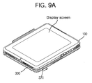
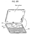
- Figs. 9a, 9b, and 9c Exemplary operations from a closed position to any open position are shown in Figs. 9a-9c.
- Rotation of the system main body 100 including the display screen preferably works together with the rotary keyboard disk assembly 332 on the keyboard case 310 of the keyboard apparatus 300.
- the user preferably needs to rotate the system main body 100, (e.g., 180 degrees) along the rotation direction of the keyboard disk assembly 332, for example, supposing that the keyboard apparatus 300 is placed on a desk.
- the computer system can perform web pad functions only (e.g., display surface facing out). This is because data input using keypad 320 is preferably not possible when the keypad 320 has not been exposed to the outside, and control unit in the system main body 100 prohibits data input through keyboard if the keyboard apparatus 300 and the main body 100 are coupled to each other in the closed position.
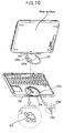
- Fig. 10 is a diagram that shows a sectional perspective view of components of a rotation detecting apparatus according to a preferred embodiment.
- the main body 100 when the user opens the system main body 100 preferably around the hinge assembly 337 of the keyboard apparatus 300 by operating the keyboard opening/closing button 371, and preferably rotates the system main body 100 at about 180 degrees along the rotation direction of the keyboard disk assembly 332, the main body 100, through a rotation detecting apparatus that can be mounted using the rotating member is preferably converted a data input mode using a keyboard.
- the rotation detecting apparatus can be secured at the rear surface of the rear case 312.
- the rotation detecting apparatus can include a lower rotation guide member 334 with a data input mode inverting switch 333 being fixated at a prescribed position on the front surface that faces the rear case 312, a keyboard disk assembly 332 and the male connector 343.
- the keyboard disk assembly 332 is disposed between the front case 311 and the lower rotation guide member 334 and coupled so that it can rotate along the guide groove formed on the lower rotation guide member 334, including a projection 335a that is coupled to the main body and generates a switching signal by contacting the data input mode inverting switch 333 when the main body rotates by a prescribed amount or to a certain angle.
- the male connector 343 can transfer the switching signal of the data input mode inverting switch 333 to the main body of the system 100.
- stopping spring 335c is supported/secured (e.g., fastened) at two positions of the upper surface of the lower rotation guide member 334 to facilitate rotation of the keyboard assembly to 180 degrees.
- Each stopping spring 335c is fixated in such way as to maintain equal distance from the center of lower rotation guide member 334 (i.e., on the concentric circle) and maintains 180 degrees to each other.
- a second projection 335b is formed on the rear surface of the keyboard disk 335 to oppose the stopping spring 335c fixated on the upper surface of the lower rotation guide member 334.
- the stopping spring 335c and the second projection 335b When the user rotates the main body at 180 degrees from the keyboard apparatus, the second projection 335b passes through the groove of the stopping spring 335c in accordance with the relative motion of the lower rotation guide member 334 and the keyboard disk 335 and can make a 'click' sound as it clicks to the groove. Therefore, the user does not stop rotating the keyboard apparatus 300 supporting the system 100 until he/she hears the click sound.
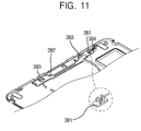
- Fig. 11 is a diagram that shows a sectional perspective view of a protection cover detachment apparatus when a front case is partially removed.
- Fig. 12 is a diagram that shows detaching the protection cover.
- the user can find it inconvenient to carry the multi-type computer system after coupling its main body to the keyboard apparatus.
- the user When coupled, the user must worry whether the main body, especially the display screen, will be damaged by being contacted with the outside.
- a protection cover detachment apparatus could be installed at the rear side of the keyboard case 310 to protect the display or glass surface on the main body 100 from external shock especially when the user needs to carry the folded computer system having system's main body 100 coupled to the keyboard apparatus 300.
- the protection cover detachment apparatus can include a protection cover 385, protection cover detachment button 381 that slides over the rear case 312, a gearing lever 382 that gears by the protection cover detachment button and a catching button 383 with a catching surface to which the protection cover clicks, gearing with the gearing lever.
- the protection cover detachment button 381 can be resiliently supported by the return spring 384 so it tends or always returns to an original position after operation.
- the cover protection detachment apparatus preferably attaches or clicks to the protection cover 385 to protect the glass surface of the display at the one side of the main body 100 from external shock. Therefore, if the user wants to carry the main body 100, he/she needs to insert a projection 386 on the protection cover 385 through the catching groove 315 that is formed on the keyboard case 310 to properly click the projection 386 to the catching button 383. On the contrary, if the user wants to take off the protection cover 385, he/she needs to push the protection cover detachment button 381 to the opposite direction, and releases the projection 386 from the catching button 383. At this time, if the user frees the catching button 383, the button preferably returns to its original position by the elasticity of the return spring 384.
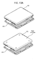
- Figs. 13a and Fig. 13b are diagrams that show components and operations to couple the system's main body to the keyboard apparatus in forward and reverse directions in accordance with preferred embodiments.
- the display could be coupled to the system 100 to face the outside.
- the system 100 can also be coupled the other way around, that is, the display could be coupled facing the keyboard apparatus, making its rear surface face the outside.
- the former is convenient in that users can input data directly in the display surface by using stylus pen and then see the input results.
- the latter has a merit in that users can keep the display surface from being damaged.
- the forward/backward connection of the keyboard apparatus 300 to the main body 100 can be made, for example, by forming one or more projections on the end of keyboard docking projection 360 to work in both directions, thereby allowing the keyboard docking projection 360 to couple to the first frame in both directions.
- the keyboard docking projections 360 can work with the keyboard separating lever 157 of the main body in both directions.
- the present invention is not intended to be so limited.
- connection of the system 100 to the keyboard apparatus 300 can be formed to allow only one single orientation.
- a reverse-insertion preventing projection 360a at one side of the keyboard docking projection 360, and one passing groove at the opposite position of the reverse-insertion preventing projection should be formed at one side of the main body for the reverse-insertion preventing projection to pass through.
- the reverse-insertion preventing projection can be interfered by a main body that does not have the passing groove for the reverse-insertion preventing projection. In this case, reverse-insertion assembly of the main body to the keyboard apparatus is made impossible, and reverse-insertion is prevented.
- an attachable/detachable keyboard apparatus of portable multi-type computer system has various advantages that can be independently, partially, and in combination achieved.
- Preferred embodiments of an attachable/detachable keyboard apparatus of portable multi-type computer system according to the present invention can be used for a computer with web pad function and notebook PC function. Users can easily attach the keyboard apparatus to the main body of the system, and input text or data only when necessary. Further, the system can be used as web pad only with the keyboard detached from the system. In addition, the keyboard apparatus can be coupled and carried with the web pad folded together.
Landscapes
- Engineering & Computer Science (AREA)
- Theoretical Computer Science (AREA)
- Computer Hardware Design (AREA)
- Physics & Mathematics (AREA)
- Human Computer Interaction (AREA)
- General Engineering & Computer Science (AREA)
- General Physics & Mathematics (AREA)
- Mathematical Physics (AREA)
- Input From Keyboards Or The Like (AREA)
Abstract
Description
- The present invention relates to a portable computer system.
- As more business is being handled outside the office, people prefer a notebook personal computer (PC) to a desktop PC or a personal digital assistant (PDA) because the notebook PCs are more convenient to carry out and operate outside of the office with high functionality.
- A related art notebook PC is one main body including a system with keyboard to input text or data attached to the main body. Although the notebook PC can be carried anywhere, its weight is rather heavy and it is occasionally inconvenient to use. To reduce the total weight, a floppy disk drive (FDD) or an optical disk drive was separated from the main body, and connected to the main body only if necessary for use.
- Related art personal digital assistances (PDAs) allow one to input data by using a stylus pen to tap a virtual keyboard on a display or actually write on the display. However, tapping the virtual keyboard on an extremely small screen is difficult. Further, when one writes characters on the liquid display that is normally sensitive to any type of pressure, a web pad recognizes the characters as a text. In doing so, however, the web pad makes a number of errors (e.g., character recognition error). Also, it is not easy to write document while the web pad is not being steadily supported or is moving.
- To overcome such the problems, one carried a separate keyboard and connected the keyboard through a wire connector to the PDA whenever necessary. Thus, the PDA recognizes input signals into the keyboard.
- U.S. Patent No. 6,108,200 discloses a method for directly connecting/detaching a separate keyboard system to/from PDA. Figs. 1a and 1b diagrammatically illustrate a prior art keyboard apparatus looks like before and after a web pad is installed thereon.
- As shown in Fig. 1a, the keyboard apparatus includes an
interface 812 mounted with a connector for connecting a web pad to upper portion of akeypad 811. Theinterface 812 is one body with akeypad cover portion 813. Normally, thecover 813 rotates around a hinge that is installed on one end of thecover 813. According to the prior art keyboard apparatus, the web pad is connected to thekeypad 811 by inserting into theinterface 812, and a user can input data, e.g., characters, by using thekeypad 811. - However, the prior art keyboard apparatus has various problems. Since the keyboard is turned on all the time to have the
keypad 812 automatically converted to a mode through which the user can input characters whenever the web pad is connected to theinterface 812, the keyboard is on even when the user does not input any data, which consumes much power. Further, if the user puts thecover portion 813 on the keyboard after the web pad is installed into the keyboard, the user cannot use the web pad. Also, thecover portion 813 can rotate only to cover thekeypad 811. - When the user wants to show the screen on the portable PC to another person while the display is opened, the user had to turn the entire main body of the computer to face that person. A rotary display that turns around a pivot at one edge of a main body was developed. However, one cannot think of carrying only the main body without display. In addition, the user generally needs a separate driving source to rotate the display. Accordingly, there should be additional space in the main body to install the rotation driving source to increase a size of the portable PC.
- Further, notebook PCs use two opening/closing buttons on a cover that includes a display to secure the cover in a closed position to the main or system body. However, such opening/closing apparatus do not work together, and a user has to use fingers of both hands at the same time in order to operate the buttons.
- The above references are incorporated by reference herein where appropriate for appropriate teachings of additional or alternative details, features and/or technical background.
- An object of the invention is to solve at least the above problems and/or disadvantages and to provide at least the advantages described hereinafter.
- Another object of the present invention is to provide a keyboard apparatus that can attach to the main body of a system being used as web pad to selectively use the keyboard to input text and data.
- Another object of the present invention is to provide a keyboard apparatus that reduces power consumption.
- Another object of the present invention is to provide a keyboard apparatus that reduces power consumption by allowing the system to operate as web pad only when closed.
- Another object of the present invention is to provide a keyboard apparatus that reduces power consumption by enabling the keypad in an open position.
- Another object of the present invention to provide a keyboard apparatus detachment apparatus of portable multi-type computer system that moves between a closed position and an open position.
- Another object of the present invention to provide a keyboard apparatus detachment apparatus of portable multi-type computer system that is capable of connecting the keyboard apparatus to the system's main body both backward and forward.
- At least the above objects and other objects and advantages can be selectively realized in a whole or in part by providing an attachable/detachable keyboard apparatus of portable multi-type computer system that includes a keyboard case having a front case and a rear case that are connected to each other to enclose a space therebetween; a keypad for inputting data being mounted on of the keyboard case; a rotating member for rotating web pad at a designated angle around the keyboard case installed on the keyboard case; a connector for connecting the key pad to the web pad to transmit signals that are inputted from the key pad to the web pad; and a keyboard connecting projection formed at one side of the rotating member for securing the keyboard to the web pad as the keyboard settles in one side of the web pad.
- In preferred embodiments according to the present invention, a user can input text and data in the system's main body being used as web pad by selectively using the keyboard, and can save power consumption by allowing the system to operate as web pad only while limiting data input through the keyboard is if the keyboard connected to the system's main body.
- To achieve at least the above objects and other advantages in a whole or in part and in accordance with the purpose of the present invention, as embodied and broadly described herein, there is provided a system that includes a keyboard case, an input device exposed in an upper surface of the keyboard case, and a connector mounted on the keyboard case for connection to a portable computer, wherein the connector rotates between a first position and a second position, wherein the keypad is disabled unless the connector is in the second position.
- To further achieve at least the above objects and other advantages in a whole or in part and in accordance with the purpose of the present invention, as embodied and broadly described herein, there is provided a keyboard apparatus that includes a keyboard case, an input device exposed in an upper surface of the keyboard case, a connector mounted on the keyboard case for detachable connection to a portable computer, wherein the connector includes a rotational disk that rotates around a fixed point relative to the upper surface of the keyboard case, and a hinge rigidly coupled to the rotational disk displaced a prescribed distanced from the fixed point.
- To further achieve at least the above objects and other advantages in a whole or in part and in accordance with the purpose of the present invention, as embodied and broadly described herein, there is provided a portable multi-type computer system that includes a web pad-type computer, a keyboard apparatus that detachably connects to the web pad, wherein the keyboard apparatus includes a keyboard case having a front case and a rear case that are coupled together to enclose a space therebetween, a keypad exposed in an upper surface of the keyboard case, and a keyboard opening/closing apparatus mounted on the keyboard case that selectively rigidly attaches the web pad to the keyboard apparatus, wherein the keypad is disabled unless the keyboard opening/closing apparatus is in an open position.
- Additional advantages, objects, and features of the invention will be set forth in part in the description which follows and in part will become apparent to those having ordinary skill in the art upon examination of the following or may be learned from practice of the invention. The objects and advantages of the invention may be realized and attained as particularly pointed out in the appended claims.
- The invention will be described in detail with reference to the followingdrawings in which like reference numerals refer to like elements wherein:
- Fig. 1a is a diagram that shows a prior art keyboard apparatus before a web pad is installed thereto;
- Fig. 1b is a diagram that shows a prior art keyboard apparatus after a web pad is installed thereto;
- Fig. 2a is a diagram that shows a perspective view of a preferred embodiment of a keyboard apparatus according to the present invention coupled to a main body of a system;
- Fig. 2b is a diagram that shows a perspective view of a preferred embodiment of a keyboard apparatus according to the present invention and a main body of a system;
- Fig. 3 is a diagram that shows a preferred embodiment of a keyboard apparatus according to the present invention for connection to a main body of a system;
- Fig. 4 is a diagram that shows a perspective view of parts of a preferred embodiment of a keyboard apparatus according to the present invention;
- Fig. 5 is a diagram that shows an outer appearance of a keyboard disk assembly and parts thereof;
- Fig. 6 is a diagram that shows parts of a hinge assembly,
- Fig. 7 is a diagram that shows a male connector coupled to a first connector cover,
- Fig. 8a is a diagram that shows a perspective view illustrating the outer appearance of a preferred embodiment of a keyboard opening/closing apparatus;
- Fig. 8b is a diagram that shows a sectional perspective view of components of a preferred embodiment of a keyboard opening/closing apparatus;
- Fig. 8c is a diagram that shows a position where a projection of the main body is operated before operating a preferred embodiment of a keyboard opening/closing apparatus;
- Fig. 8d is a diagram that shows a position where a projection of the main body is operated after operating a preferred embodiment of a keyboard opening/closing apparatus;
- Fig. 8e is a diagram that shows a state of a system after a preferred embodiment of a keyboard opening/closing apparatus is connected to a main body,
- Figs. 9a through 9c are diagrams that show exemplary operations of opening and inverting a preferred embodiment of a keyboard apparatus;
- Fig. 10 is a diagram that shows a sectional perspective view depicting components of a rotation detecting apparatus;
- Fig. 11 is a diagram that shows a sectional perspective view of a protection cover detachment apparatus when a front case is partially cut off;
- Fig. 12 is a diagram that demonstrates exemplary detachment of a protection cover; and
- Figs. 13a and Fig. 13b are diagrams that show a system main body can be coupled to a keyboard apparatus in forward and reverse directions.
-
- Figs. 2a-2b are diagrams showing perspective views of a preferred embodiment of a keyboard apparatus according to the present invention that can be coupled to a main body of a system. As shown in Fig. 2a,
keyboard apparatus 300 is appropriate for use in a portable multi-system (e.g., web pad function and notebook PC function) computer. Thekeyboard apparatus 300 can be attached to amain body 100 of a system (e.g., web pad), and one can selectively use a keyboard if data or text should be input. Hence, there is no need to keep the keyboard turned on to stand by for key input after installing thekeyboard apparatus 300, and as a result, power consumption can be significantly reduced. When the computer is used as a web pad, a user can detach the keyboard apparatus from the main body and carry more conveniently. However, the present invention is not intended to be so limited. For example, the web pad can be attached in a closed accessible or protected position to a keyboard apparatus. - Preferred embodiments of an attachable/
detachable keyboard apparatus 300 of portable multi-type computer system as shown in Figs. 2a-13b can include akeyboard case 310, akeypad 320 through which a user can input data and a rotatingmember 330 that enables thekeyboard case 310 to rotate aroundmain body 100 of the system, e.g., web pad, at a designated angle and that inverts the system from pen input mode using astylus 200 to keyboard input mode that uses a keyboard through a rotation operation. Aconnector 343 can couple thekey pad 320 to the system'smain body 100 for transmitting signals having been input from thekey pad 320 to the system'smain body 100. Akeyboard docking projection 360 can secure thekeyboard apparatus 300 to the system'smain body 100 to protect a display screen as desired or when the key input is not performed for an extended period of time. - A fixed
projection insert hole 313 is preferably formed at one side of thekeyboard case 310 for mounting on a docking system or for connecting the system's main body to a connector of a docking system, external expansion apparatus or the like, if necessary while themain body 100 can remain connected to the keyboard. Also, at the other side of thekeyboard case 310, there is a plurality of passinggrooves 314 that can secure projections for the purpose of making the connection between a cradle, another expansion apparatus, and the main body of thesystem 100 more secure while reducing or avoiding any interference to web pad (e.g., system) securing projections. - The main body of the
system 100 preferably has a display at one front surface and a battery cover (not shown) at its opposing rear surface. Except the display and the rear, the other four edges are all sides. Preferably, one side of themain body 100 includes a plurality of keyboard docking projection insert holes (not shown in Figs. 2a-2b) for coupling to thekeyboard apparatus 300. - Through a keyboard docking projection insert hole, the
male connector 343 andkeyboard docking projection 360 can be inserted and fixated with a prescribed movement. More specifically, if a user wants to connect thekeyboard 300 to themain body 100 of the system, the user should pass thekeyboard docking projection 360 through the keyboard docking projection insert hole, and then lock in a locking projection detaching side preferably at the end of afirst frame 155 as shown in Fig. 3. - There can be a reverse-insertion preventing mechanism such a reverse-
insertion preventing projection 360a nearby thekeyboard docking projection 360, and a groove (not shown) at an opposite side of themain body 100, through which the reverse-insertion preventing projection 360a can pass. In this manner, the display is preferably coupled, facing outward from the system'smain body 100 while the rear of the main body is not turned to the outside. - However, reverse insertion can be allowed, and the reverse-
insertion preventing projection 360a does not have to be formed. In such case, the display surface of the system could be set up to face the outside, or the display surface could face the key board apparatus with the rear of thesystem 100 facing outward. - Fig. 2a represents the
keyboard apparatus 300 coupled to themain body 100 of the system. Fig. 3 is a diagram that shows a sectional perspective view of parts of thekeyboard apparatus 300 according to the present invention. - As shown in at least Figs. 3-4, a type of rotating
member 330 can be employed to rotate the system'smain body 100 around thekeyboard apparatus 300 at a designated angle. Preferably, the rotatingmember 330 is secured on the rear of afront case 311 for better rotation. The rotatingmember 330 can include an upperrotation guide member 331 disposed at the rear surface of thefront case 311, akeyboard disk assembly 332 that rotates along aguide rail 331a formed on the rear surface of the upperrotation guide member 331 and a lowerrotation guide member 334 for fastening the upperrotation guide member 331 and thekeyboard disk assembly 332 preferably to a boss formed on the rear surface of thefront case 311. The lowerrotation guide member 334 can include a data inputmode inverting switch 333 at a certain position of the front surface. - The
guide rail 331a formed on the rear surface of the upperrotation guide member 331 is preferably a projected guide surface with a concentric circular shape. However, the present invention is not intended to be so limited. Theguide rail 331a should allow rotation relative to the guide surface formed on the upper surface of the lowerrotation guide member 334 while coming in contact with the guide surface at the same time. The boss on the rear surface of thefront case 311 can go through a certain position of the upperrotation guide member 331 on which a plurality of throughholes 334 is formed to make the upperrotation guide member 331 better supported by the boss. - Fig. 5 is a diagram that shows an outer appearance of an exemplary keyboard disk assembly and functionally decomposed parts of the exemplary keyboard disk assembly. Fig. 6 is a diagram that shows a decomposition of parts of an exemplary hinge assembly.
- As shown in Figs. 5-6, the
keyboard disk assembly 332 is set up to securely rotate along aguide rail 331a formed on the rear surface of the upperrotation guide member 331. Thekeyboard disk assembly 332 includes akeyboard disk 335 that rotates along aguide rail 331a formed on the rear surface of the upperrotation guide member 331. Thekeyboard disk 335 can include aprojection 335a on the rear side that can contact with a data inputmode inverting switch 333 along the rotation, ahinge frame 336 being screwed onto thekeyboard disk 335, and ahinge assembly 337 that rotates at one side of thehinge frame 336. - The
hinge assembly 337 further can include afirst connector cover 338; asecond connector cover 339 on an opposite side to thefirst connector cover 338 and a first andsecond hinges first connector cover 338 and thesecond connector cover 339 being fastened (e.g., screwed) at both ends thereof. Ahinge cover 342 can fasten the first andsecond hinges 340 and 341 (e.g., with hingedsections hinge frame 336, and at the same time cover them. - Fig. 6 shows exemplary internal/external couplings. The
hinge frame 336 can be screwed down to the upper end of thekeyboard disk 335, and thehinge assembly 337 is coupled to the edge of the upper end of thehinge frame 336 in such manner that thehinge assembly 337 may rotate between thekeyboard apparatus 300 and thesystem 100 of the system at a designated angle. - The
first connector cover 338 and thesecond connector cover 339 on thehinge assembly 337 are preferably screwed onto each other while facing each other. Arubber bumper 344 can be adhered to part of the screw including the screw head, making the outer appearance thereof attractive. - In addition,
male connector 343 for accessing/transmitting input signals from thekeyboard apparatus 300 to the system'smain body 100 is preferably installed close to the center of thehinge assembly 337. Themale connector 343 is attached in such way that themale connector 346 faces the front side bypassing through amale connector hole 345 from the rear of thefirst connector cover 338. Usually, themale connector 346 is fastened (e.g., soldered) up onto a small-sized auxiliaryprint circuit substrate 347, and asignal cable 348 for transferring input signals from thekeyboard apparatus 300 to themain body 100 is coupled to one side of the auxiliaryprint circuit substrate 347. The auxiliaryprint circuit substrate 347 can be assembled/secured onto the boss on the rear surface of thefirst connection cover 338, being resiliently supported by aseparate plate spring 349. - The
male connector 346 being assembled/secured onto thefirst connector cover 338 preferably can move to every direction, namely up and down, and right to left. Such a connector can simplify connection of thekeyboard apparatus 300 to the systemmain body 100, and reduce or prevent any possible damage on each connector as the keyboard is coupled to an arm connector, which is an opposite part to themale connector 346, guiding both opposite sites to be bonded together. - The other end of the
signal cable 348 can be guided by acable guide groove 335e that is formed on thekeyboard disk 335, and pass through a cable throughhole 335d that is formed on the central part of thekeyboard disk 335. Thesignal cable 348 eventually can be coupled to a print circuit substrate (not shown) mounted in the keyboard apparatus. - At certain places of the rear of the
keyboard disk 335, there is preferably formed first andsecond projections mode inverting switch 333, which can be secured at an upper opposite position to the lowerrotation guide member 334, to preferably drive an inverting lever, thereby preferably realizing inversion from data input mode using keyboard to data input mode using a stylus pen or the like. The data inputmode inverting switch 333 can be electrically coupled to the print circuit substrate (not shown) of the keyboard apparatus. - After the
keyboard disk assembly 332 is coupled to the upperrotation guide member 331 using aguide groove 335f, enabling them to rotate with each other, it is fastened using the lowerrotation guide member 334 onto the rear surface of thefront case 311. Thus, thefront case 311 can be attached (e.g., screwed) with therear case 312. - Fig. 7 is a diagram that shows an exemplary coupling between a male connector and a first connector cover. As shown in Fig. 10, the boss, which is formed on the rear surface of the
first connector cover 338 for facilitating themale connector 346 to move around, has two steps. Asecond step 338b with an internal arm screw is screwed onto the center of afirst step 338a at the auxiliaryprint circuit substrate 347. Preferably, height of thesecond step 338b is greater than sum of thicknesses of the auxiliaryprint circuit substrate 347 and theplate spring 349, and external size of thesecond step 338b is smaller than the screw hole on the auxiliaryprint circuit substrate 347. In this manner, the auxiliaryprint circuit substrate 347 can move to every direction, i.e., back and forth (e.g., A direction) and right to left (e.g., B direction), receiving elasticity of theplate spring 349 even after the printedcircuit substrate 347 is screwed down. - Further, a
spring projection 349a is formed on the rear surface of theplate spring 349. Preferably, the projection is directed to thefirst connector cover 338 in order to secure the auxiliaryprint circuit substrate 347 always to thefirst step 338a by theplate spring 349. - Fig. 8a is a diagram that shows a perspective view illustrating the outer appearance of an exemplary keyboard opening/closing apparatus. Fig. 8b is a sectional perspective view diagram showing major components of the exemplary keyboard opening/closing apparatus. Fig. 8c is a diagram showing a position of a projection of the main body before operating the keyboard opening/closing apparatus. Fig. 8d is a diagram showing a position of a projection of the main body after operating the keyboard opening/closing apparatus. Fig. 8e is a diagram that shows a position of the system after the keyboard opening/closing apparatus is properly coupled to the system main body.
- As shown in Figs. 8a-8e, a keyboard opening/
closing apparatus 370 is preferably installed at one side of the front of thekeyboard case 310, in order to facilitate connection and separation of thekeyboard apparatus 300 to and from the system'smain body 100 especially when the user wants to use the computer system that had been coupled to thekeyboard apparatus 300 by folding or spreading it. More specifically, the keyboard opening/closing apparatus 370 can include a keyboard opening/closing button 371, abutton receiving hole 372 formed on the keyboard case to receive the button and afirst operating lever 373 that can slide right to left, being guided by a guide boss mounted on the rear case and operated by the keyboard opening/closing button 371. A mainbody locking projection 374 can rotate as the first operating lever starts operating. - Preferably, the main
body locking projection 374 is supported by afirst catching pin 375 to be able to rotate on therear case 312. Also, asecond operating lever 376 can be used to facilitate rotation of the mainbody locking projection 374 by thefirst operating lever 373. One side of thesecond operating lever 376 can work together with thefirst operating lever 373 by asecond catching pin 377. The other side of thesecond operating lever 376 can be caught by a hole that is formed at one side of the mainbody locking projection 374 in order to transfer sliding motion of thefirst operating lever 373, and eventually enabling the mainbody locking projection 374 to rotate. - Further, one side of the first catching
pin 375 can guide thefirst operating lever 373. In such case, partial end of thefirst operating lever 373 is pleated, and includes a guide groove to received or guide the first catchingpin 375. - Preferably, two main
body locking projections 374 are respectively installed on both sides of the front of thekeyboard case 310, each being separated by certain distance, in order to maintain secure connection betweenkeyboard apparatus 300 and system'smain body 100. Other components for driving the mainbody locking projection 374 are assembled in such a manner as to cooperate together on thefirst operating lever 373 in accordance with opening/closing operation of the keyboard opening/closing button 371. - Operations of the main
body locking projection 374 together with the keyboard opening/closing button 371 to couple thekeyboard apparatus 300 with thesystem 100, or how these two are disconnected from each other will now be described. If the user pushes the keyboard opening/closing button 371 to the opening direction (e.g., right direction), thefirst operating lever 373 on the rear surface of the keyboard opening/closing button can move to the right direction also. When thefirst operating lever 373 slides, thesecond operating lever 376 moves to the right direction at the same time. - Motion of the
second operating lever 376 is transferred to the mainbody locking projection 374 that rotates around the first catchingpin 375, and the mainbody locking projection 374 preferably rotates counterclockwise. In this way, the mainbody locking projection 374 is properly secured to a sidewall of the catching groove that can be formed on the case of a main body of thesystem 100 as shown in Fig. 8e. - On the contrary, if the user pushes the keyboard opening/
closing button 371 in a reverse direction (e.g., the left direction), thefirst operating lever 373 moves to the left, and eventually, the mainbody locking projection 374 rotates clockwise. As a result, the sidewall of the catching groove that is formed on the case of themain body 100 breaks away from the catching part on the mainbody locking projection 374, and the system'smain body 100 can be opened from thekeyboard apparatus 300. - In a final position (e.g., the main
body locking projection 374 is fastened or caught by the sidewall of the catching groove on the case of themain body 100 conforming to the operation of the keyboard opening/closing button 371), a tension device such astension unit 378 can be further installed at the rear surface of the keyboard opening/closing button 371 to lock the keyboard opening/closing button 371 to the final position. Atension unit groove 379 is installed at an opposite position to thetension unit 378 on therear case 312. In this manner, thetension unit 378 on the rear surface of the keyboard opening/closing button 371 can preferably be safely locked to thetension unit groove 379, and, the keyboard opening/closing button 371 can be locked to its final position. Hence, when the main body and the keyboard are closed, the keyboard opening/closing button 371 remains locked, so the mainbody locking projection 374 cannot easily be separated from the catching groove on the case of thesystem 100 as shown in Fig. 8e. - When the user wants to open a keyboard apparatus such as
keyboard apparatus 300 that is interlocked to the main body of thecomputer system 100, given that the user had been carrying the computer system coupled with thekeyboard apparatus 300 or the user had been using the computer system 100 (e.g., web pad), the user can operate the keyboard opening/closing button 371 and open (e.g., unfold) the web padmain body 100 around thehinge assembly 337 of thekeyboard apparatus 300. - In such a case, the user comes to face the rear surface of the system
main body 100, not a display screen or touch screen. Therefore, it is necessary to secure the position of the display screen by rotating it (e.g., counterclockwise) to face the user (refer to Figs. 9a, 9b, and 9c). Exemplary operations from a closed position to any open position are shown in Figs. 9a-9c. - Rotation of the system
main body 100 including the display screen preferably works together with the rotarykeyboard disk assembly 332 on thekeyboard case 310 of thekeyboard apparatus 300. To rotate themain body 100 having been opened from thekeyboard apparatus 300 toward the user's direction, the user preferably needs to rotate the systemmain body 100, (e.g., 180 degrees) along the rotation direction of thekeyboard disk assembly 332, for example, supposing that thekeyboard apparatus 300 is placed on a desk. - When the user uses the computer while carrying the computer system where the
keyboard apparatus 300 is coupled to the system'smain body 100, the computer system can perform web pad functions only (e.g., display surface facing out). This is because datainput using keypad 320 is preferably not possible when thekeypad 320 has not been exposed to the outside, and control unit in the systemmain body 100 prohibits data input through keyboard if thekeyboard apparatus 300 and themain body 100 are coupled to each other in the closed position. - Fig. 10 is a diagram that shows a sectional perspective view of components of a rotation detecting apparatus according to a preferred embodiment. As shown in Fig. 10, when the user opens the system
main body 100 preferably around thehinge assembly 337 of thekeyboard apparatus 300 by operating the keyboard opening/closing button 371, and preferably rotates the systemmain body 100 at about 180 degrees along the rotation direction of thekeyboard disk assembly 332, themain body 100, through a rotation detecting apparatus that can be mounted using the rotating member is preferably converted a data input mode using a keyboard. The rotation detecting apparatus can be secured at the rear surface of therear case 312. The rotation detecting apparatus can include a lowerrotation guide member 334 with a data inputmode inverting switch 333 being fixated at a prescribed position on the front surface that faces therear case 312, akeyboard disk assembly 332 and themale connector 343. Thekeyboard disk assembly 332 is disposed between thefront case 311 and the lowerrotation guide member 334 and coupled so that it can rotate along the guide groove formed on the lowerrotation guide member 334, including aprojection 335a that is coupled to the main body and generates a switching signal by contacting the data inputmode inverting switch 333 when the main body rotates by a prescribed amount or to a certain angle. Themale connector 343 can transfer the switching signal of the data inputmode inverting switch 333 to the main body of thesystem 100. - When the user opens the system
main body 100 around a first andsecond hinges keyboard apparatus 300 by operating the keyboard opening/closing button 371, and rotates themain body 100 preferably about 180 degrees along the rotation direction of thekeyboard disk assembly 332,projection 335a of the rotation detecting apparatus and the data inputmode inverting switch 333 come in contact with each other. As a result, a switching signal is preferably generated. The switching signal is then sent to a control unit (not shown) of themain body 100 through themale connector 343. In conforming to the switching signal, themain body 100 of the system switches to the keyboard input mode so the user can input data by using the keyboard. - Preferably, stopping
spring 335c is supported/secured (e.g., fastened) at two positions of the upper surface of the lowerrotation guide member 334 to facilitate rotation of the keyboard assembly to 180 degrees. Each stoppingspring 335c is fixated in such way as to maintain equal distance from the center of lower rotation guide member 334 (i.e., on the concentric circle) and maintains 180 degrees to each other. Also, asecond projection 335b is formed on the rear surface of thekeyboard disk 335 to oppose the stoppingspring 335c fixated on the upper surface of the lowerrotation guide member 334. - Operations of the stopping
spring 335c and thesecond projection 335b will now be described. When the user rotates the main body at 180 degrees from the keyboard apparatus, thesecond projection 335b passes through the groove of the stoppingspring 335c in accordance with the relative motion of the lowerrotation guide member 334 and thekeyboard disk 335 and can make a 'click' sound as it clicks to the groove. Therefore, the user does not stop rotating thekeyboard apparatus 300 supporting thesystem 100 until he/she hears the click sound. - Fig. 11 is a diagram that shows a sectional perspective view of a protection cover detachment apparatus when a front case is partially removed. Fig. 12 is a diagram that shows detaching the protection cover.
- The user can find it inconvenient to carry the multi-type computer system after coupling its main body to the keyboard apparatus. When coupled, the user must worry whether the main body, especially the display screen, will be damaged by being contacted with the outside.
- To reduce or prevent any possible damage on the display surface of the main body, users can use a protection cover. More specifically, a protection cover detachment apparatus could be installed at the rear side of the
keyboard case 310 to protect the display or glass surface on themain body 100 from external shock especially when the user needs to carry the folded computer system having system'smain body 100 coupled to thekeyboard apparatus 300. - The protection cover detachment apparatus can include a
protection cover 385, protectioncover detachment button 381 that slides over therear case 312, a gearinglever 382 that gears by the protection cover detachment button and acatching button 383 with a catching surface to which the protection cover clicks, gearing with the gearing lever. The protectioncover detachment button 381 can be resiliently supported by thereturn spring 384 so it tends or always returns to an original position after operation. - The cover protection detachment apparatus preferably attaches or clicks to the
protection cover 385 to protect the glass surface of the display at the one side of themain body 100 from external shock. Therefore, if the user wants to carry themain body 100, he/she needs to insert aprojection 386 on theprotection cover 385 through the catchinggroove 315 that is formed on thekeyboard case 310 to properly click theprojection 386 to thecatching button 383. On the contrary, if the user wants to take off theprotection cover 385, he/she needs to push the protectioncover detachment button 381 to the opposite direction, and releases theprojection 386 from the catchingbutton 383. At this time, if the user frees the catchingbutton 383, the button preferably returns to its original position by the elasticity of thereturn spring 384. - Figs. 13a and Fig. 13b are diagrams that show components and operations to couple the system's main body to the keyboard apparatus in forward and reverse directions in accordance with preferred embodiments. As shown in Fig. 13a, the display could be coupled to the
system 100 to face the outside. Also shown in Fig. 13a, thesystem 100 can also be coupled the other way around, that is, the display could be coupled facing the keyboard apparatus, making its rear surface face the outside. The former is convenient in that users can input data directly in the display surface by using stylus pen and then see the input results. On the other hand, the latter has a merit in that users can keep the display surface from being damaged. - The forward/backward connection of the
keyboard apparatus 300 to themain body 100 can be made, for example, by forming one or more projections on the end ofkeyboard docking projection 360 to work in both directions, thereby allowing thekeyboard docking projection 360 to couple to the first frame in both directions. As shown in Fig. 13b, thekeyboard docking projections 360 can work with thekeyboard separating lever 157 of the main body in both directions. However, the present invention is not intended to be so limited. - For example, the connection of the
system 100 to thekeyboard apparatus 300 can be formed to allow only one single orientation. To connect thesystem 100 to the keyboard apparatus while keeping the display screen facing the outside, there should be a reverse-insertion preventing projection 360a at one side of thekeyboard docking projection 360, and one passing groove at the opposite position of the reverse-insertion preventing projection should be formed at one side of the main body for the reverse-insertion preventing projection to pass through. In this case, if one assembles the system to make the rear side of themain body 100 face the outside, the reverse-insertion preventing projection can be interfered by a main body that does not have the passing groove for the reverse-insertion preventing projection. In this case, reverse-insertion assembly of the main body to the keyboard apparatus is made impossible, and reverse-insertion is prevented. - As described above, preferred embodiments of an attachable/detachable keyboard apparatus of portable multi-type computer system according to the present invention have various advantages that can be independently, partially, and in combination achieved. Preferred embodiments of an attachable/detachable keyboard apparatus of portable multi-type computer system according to the present invention can be used for a computer with web pad function and notebook PC function. Users can easily attach the keyboard apparatus to the main body of the system, and input text or data only when necessary. Further, the system can be used as web pad only with the keyboard detached from the system. In addition, the keyboard apparatus can be coupled and carried with the web pad folded together.
Claims (19)
- A system, comprising:wherein the keypad is disabled unless the connector is in the second position.a keyboard case;an input device exposed in an upper surface of the keyboard case; anda connector mounted on the keyboard case for connection to a portable computer, wherein the connector rotates between a first position and a second position,
- The system of claim 1, wherein the keyboard case comprises a front case and a rear case that are coupled together to enclose a space therebetween, wherein the connector comprises:a rotating member that is configured to rotate a web pad at a designated angle around the keyboard case being installed on an upper portion of the keyboard case;a male connector for connection of the input unit to transmit signals that are outputted from the input unit; anda keyboard docking projection at one side of the rotating member configured to secure the keyboard case to the web pad.
- The system of claim 2, wherein the keyboard docking projection is configured to connect with first and second different orientations to the web pad.
- The system of claim 1, wherein the connector comprises:a rotational disk that rotates around a fixed point relative to the upper surface of the keyboard case; anda hinge rigidly coupled to the rotational disk displaced a prescribed distanced from the fixed point.
- The system of claim 1, wherein a sensor is configured to sense when the portable computer is coupled to the connector, wherein the first position is a closed position and a second position is an open position, and wherein the keypad is disabled based on the sensor.
- A keyboard apparatus, comprising:a keyboard case;an input device exposed in an upper surface of the keyboard case;a connector mounted on the keyboard case for detachable connection to a portable computer, wherein the connector comprises,a rotational disk that rotates around a fixed point relative to the upper surface of the keyboard case, anda hinge rigidly coupled to the rotational disk displaced a prescribed distanced from the fixed point.
- The keyboard apparatus of claim 6, wherein the rotational disk rotates between a first position and a second position, wherein the input device is disabled unless the rotational disk is in the second position, and wherein the connector is configured to align with an outer edge of the keyboard case in the first position and align with an edge of the input device in the second position.
- The keyboard apparatus of claim 6, wherein the rotational disk comprises:an upper rotation guide member coupled below the upper surface of the keyboard case;a keyboard disk assembly that rotates along a guide rail formed on a rear surface of the upper rotation guide member, anda lower rotation guide member fastened to the upper rotation guide member with the keyboard disk assembly therebetween, wherein the lower rotation guide member includes a data input mode switch at a designated position on a front surface.
- The keyboard apparatus of claim 8, wherein the keyboard disk assembly comprises:a keyboard disk that rotates along the guide rail on the rear surface of the upper rotation guide member and includes a projection on a lower surface to selectively contact with the data input mode switch along the rotation between an open position and the closed position;a hinge frame that is fastened onto the keyboard disk; anda hinge assembly that rotates at a designated angle at one side of the hinge frame.
- The keyboard apparatus of claim 9, wherein the hinge assembly comprises:a first connector cover;a second connector cover that is set up at an opposite side to the first connector cover,a first and second hinges separated by a prescribed distance and disposed between the first connector cover and the second connector cover, wherein the first and second covers are securely coupled together, anda hinge cover that fastens the first and second hinges onto the hinge frame while covering the first and second hinges.
- The keyboard apparatus of claim 9, wherein the rotation of the connector causes the data input mode switch to convert the input device from a first mode to a second mode, wherein the input device is disabled in the first mode and enabled in the second mode.
- A portable multi-type computer system, comprising:a web pad-type computer,a keyboard apparatus that detachably connects to the web pad, wherein the keyboard apparatus comprises,a keyboard case having a front case and a rear case that are coupled together to enclose a space therebetween,a keypad exposed in an upper surface of the keyboard case, anda keyboard opening/closing apparatus mounted on the keyboard case that selectively rigidly attaches the web pad to the keyboard apparatus, wherein the keypad is disabled unless the keyboard opening/closing apparatus is in an open position.
- The portable multi-type computer system of claim 12, wherein the keyboard opening/closing apparatus comprises a rotating member that comprises:a rotational disk that rotates around a fixed point relative to the upper surface of the keyboard case; anda rigidly coupled to the rotational disk displaced a prescribed distanced from the fixed point.
- The portable multi-type computer system of claim 12, wherein the keyboard opening/closing apparatus comprises a docking projection on one side of the keyboard opening/closing apparatus that secures the web pad to the keyboard opening/closing apparatus, wherein the web pad is rotatably attached by the docking projection to cover the keypad in a closed position with a first surface in a first orientation and to cover the keypad with a second surface in a second orientation.
- The portable multi-type computer system of claim 14, wherein the web pad has a touch sensitive display unit for viewing information processed by the web pad exposed in the first surface, and wherein the display unit can be used to operate the web pad in the second orientation when the keyboard apparatus is in a closed position.
- The portable multi-type computer system of claim 15, wherein the keypad is accessible in the open position and covered in the closed position, and a fastener locks the web pad to the keyboard apparatus in the both first and second orientation when in the closed position.
- The portable multi-type computer system of claim 16, wherein the rotational disk comprises:an upper rotation guide member coupled to a rear surface of the front case;a keyboard disk assembly that rotates along a guide rail formed on a rear surface of the upper rotation guide member, anda lower rotation guide member fastened to the upper rotation guide member with the keyboard disk assembly therebetween, wherein the lower rotation guide member includes a data input mode switch at a designated position on a front surface.
- The portable multi-type computer system of claim 17, wherein the keyboard disk assembly comprises:a keyboard disk that rotates along the guide rail on the rear surface of the upper rotation guide member and includes a projection on a lower surface to selectively contact with the data input mode switch along the rotation between an open position and the closed position;a hinge frame that is fastened onto the keyboard disk; anda hinge assembly that rotates at a designated angle at one side of the hinge frame.
- The portable multi-type computer system of claim 18, wherein the hinge assembly comprises:a first connector cover;a second connector cover that is set up at an opposite side to the first connector cover,a first and second hinges separated by a prescribed distance and disposed between the first connector cover and the second connector cover, wherein the first and second covers are securely coupled together at both ends thereof; anda hinge cover that fastens the first and second hinges onto the hinge frame while covering the first and second hinges.
Applications Claiming Priority (2)
| Application Number | Priority Date | Filing Date | Title |
|---|---|---|---|
| KR1020020051609A KR100924038B1 (en) | 2002-08-29 | 2002-08-29 | Keyboard removal device for portable hybrid computer |
| KR2002051609 | 2002-08-29 |
Publications (3)
| Publication Number | Publication Date |
|---|---|
| EP1411413A2 true EP1411413A2 (en) | 2004-04-21 |
| EP1411413A3 EP1411413A3 (en) | 2010-05-26 |
| EP1411413B1 EP1411413B1 (en) | 2017-03-08 |
Family
ID=31973574
Family Applications (1)
| Application Number | Title | Priority Date | Filing Date |
|---|---|---|---|
| EP03006225.1A Expired - Lifetime EP1411413B1 (en) | 2002-08-29 | 2003-03-20 | Attachable/detachable keyboard apparatus of portable computer system |
Country Status (4)
| Country | Link |
|---|---|
| US (1) | US6781819B2 (en) |
| EP (1) | EP1411413B1 (en) |
| KR (1) | KR100924038B1 (en) |
| CN (1) | CN1229711C (en) |
Cited By (2)
| Publication number | Priority date | Publication date | Assignee | Title |
|---|---|---|---|---|
| EP1418487A2 (en) | 2002-11-11 | 2004-05-12 | Lg Electronics Inc. | Portable computer and method |
| TWI659442B (en) * | 2018-01-17 | 2019-05-11 | 大陸商東莞寶德電子有限公司 | Detachable mechanical keyboard |
Families Citing this family (171)
| Publication number | Priority date | Publication date | Assignee | Title |
|---|---|---|---|---|
| JP3884981B2 (en) * | 2002-03-04 | 2007-02-21 | アルプス電気株式会社 | Keyboard input device |
| US6788527B2 (en) * | 2002-05-31 | 2004-09-07 | Hewlett-Packard Development Company, L.P. | Tablet computer keyboard and system and method incorporating same |
| KR100460956B1 (en) * | 2002-07-03 | 2004-12-09 | 삼성전자주식회사 | A Keyboard of a personal digital assistant |
| TWM242782U (en) * | 2002-10-02 | 2004-09-01 | Wistron Corp | Assembled device of personal digital assistant (PDA) |
| US6877919B2 (en) * | 2003-02-03 | 2005-04-12 | Minebea Co., Ltd. | Foldable keyboard |
| TWI222309B (en) * | 2003-03-12 | 2004-10-11 | Primax Electronics Ltd | Command input device integrated into portable communication apparatus |
| TWM250194U (en) * | 2003-04-16 | 2004-11-11 | Aopen Inc | Cover applied to a computer with a display |
| US6980420B2 (en) * | 2003-06-09 | 2005-12-27 | Acer Inc. | Portable electronic device with a docking unit |
| US7145766B2 (en) * | 2003-10-16 | 2006-12-05 | Hewlett-Packard Development Company, L.P. | Display for an electronic device |
| TWI252072B (en) * | 2005-03-04 | 2006-03-21 | Tatung Co Ltd | Cover positioning structure of dual-usage portable computer |
| JP2006277116A (en) * | 2005-03-28 | 2006-10-12 | Fujitsu Ltd | Electronic equipment and hinge unit |
| US7719826B1 (en) * | 2005-07-01 | 2010-05-18 | Apple Inc. | Integrated access cover |
| US8907898B2 (en) * | 2005-10-31 | 2014-12-09 | Hewlett-Packard Development Company, L.P. | Tablet computer overlay membrane |
| CN100555163C (en) * | 2006-07-19 | 2009-10-28 | 华宇电脑股份有限公司 | Tablet computer and keyboard containing method thereof |
| KR100824722B1 (en) * | 2006-07-25 | 2008-04-24 | 엘지전자 주식회사 | Removable input device for mobile device |
| KR100695680B1 (en) * | 2006-08-14 | 2007-03-16 | (주)태원종합기술단건축사사무소 | Landscape vegetation fence structure installed in building complex |
| EP2051485A1 (en) * | 2007-10-15 | 2009-04-22 | Sony Ericsson Mobile Communications AB | Electronic device with a display unit being movable in relation to a base unit |
| JP5051027B2 (en) * | 2008-06-27 | 2012-10-17 | 富士通株式会社 | Assembly |
| JP4992836B2 (en) * | 2008-06-27 | 2012-08-08 | 富士通株式会社 | Electronics |
| TWM380697U (en) * | 2009-10-20 | 2010-05-11 | Wistron Corp | Switching unit and cover-lifting type electronic device |
| JP2011141921A (en) | 2010-01-06 | 2011-07-21 | Funai Electric Co Ltd | Optical disc playback apparatus |
| USD633908S1 (en) | 2010-04-19 | 2011-03-08 | Apple Inc. | Electronic device |
| USD627778S1 (en) | 2010-04-19 | 2010-11-23 | Apple Inc. | Electronic device |
| US8573394B2 (en) * | 2010-05-06 | 2013-11-05 | Clamcase, Llc | Electronic device case and method of use |
| US12164342B2 (en) | 2010-11-04 | 2024-12-10 | Parker May | Adjustable keyboard for front and back typing |
| TWD152486S (en) * | 2011-06-17 | 2013-03-21 | 三星電子股份有限公司 | Notebook computer |
| USD664532S1 (en) * | 2011-06-17 | 2012-07-31 | Samsung Electronics Co., Ltd. | Notebook computer |
| USD664533S1 (en) * | 2011-06-23 | 2012-07-31 | Samsung Electronics Co., Ltd. | Notebook computer |
| USD664535S1 (en) * | 2011-06-23 | 2012-07-31 | Samsung Electronics Co., Ltd. | Notebook computer |
| TWD155088S (en) * | 2011-06-23 | 2013-08-01 | 三星電子股份有限公司 | Notebook computer |
| US9405326B2 (en) * | 2011-06-27 | 2016-08-02 | Lenovo (Beijing) Co., Ltd. | Connecting device, electronic equipment and notebook computer with connecting device |
| JP5811737B2 (en) * | 2011-09-26 | 2015-11-11 | 富士通株式会社 | Electronic equipment |
| USD682821S1 (en) * | 2011-10-25 | 2013-05-21 | Samsung Electronics Co., Ltd. | Notebook computer |
| USD682822S1 (en) * | 2011-10-25 | 2013-05-21 | Samsung Electronics Co., Ltd. | Notebook computer |
| USD669076S1 (en) | 2011-11-15 | 2012-10-16 | Elo Touch Solutions, Inc. | Touch monitor |
| TWD153882S (en) * | 2011-11-23 | 2013-06-01 | 三星電子股份有限公司 | Notebook computer |
| TWD151171S (en) * | 2011-11-23 | 2013-01-01 | 三星電子股份有限公司 | Notebook computer |
| USD687430S1 (en) * | 2011-12-01 | 2013-08-06 | Samsung Electronics Co., Ltd. | Notebook computer |
| USD687029S1 (en) * | 2011-12-01 | 2013-07-30 | Samsung Electronics Co., Ltd. | Notebook computer |
| TWD151656S (en) * | 2011-12-14 | 2013-02-01 | 三星電子股份有限公司 | Notebook computer |
| TWD153331S (en) * | 2011-12-14 | 2013-05-01 | 三星電子股份有限公司 | Notebook computer |
| USD686202S1 (en) * | 2011-12-14 | 2013-07-16 | Samsung Electronics Co., Ltd. | Notebook computer |
| TWI481996B (en) * | 2011-12-14 | 2015-04-21 | Wistron Corp | Support stand and electronic device having the same |
| TWD151657S (en) * | 2011-12-20 | 2013-02-01 | 三星電子股份有限公司 | Notebook computer |
| TWD151658S (en) * | 2011-12-20 | 2013-02-01 | 三星電子股份有限公司 | Netbook computer |
| TWI502311B (en) * | 2012-01-06 | 2015-10-01 | Wistron Corp | Expanding device for portable electronic apparatus |
| USD682825S1 (en) * | 2012-01-09 | 2013-05-21 | Samsung Electronics Co., Ltd. | Portable computer |
| TWD152710S (en) * | 2012-01-09 | 2013-04-01 | 三星電子股份有限公司 | Portable computer |
| TWD152707S (en) * | 2012-01-09 | 2013-04-01 | 三星電子股份有限公司 | Portable computer |
| USD689046S1 (en) * | 2012-01-09 | 2013-09-03 | Samsung Electronics Co., Ltd. | Portable computer |
| USD682827S1 (en) * | 2012-01-09 | 2013-05-21 | Samsung Electronics Co., Ltd. | Portable computer |
| US9354748B2 (en) | 2012-02-13 | 2016-05-31 | Microsoft Technology Licensing, Llc | Optical stylus interaction |
| USD701858S1 (en) * | 2012-02-24 | 2014-04-01 | Samsung Electronics Co., Ltd. | Notebook computer |
| US9064654B2 (en) | 2012-03-02 | 2015-06-23 | Microsoft Technology Licensing, Llc | Method of manufacturing an input device |
| USRE48963E1 (en) | 2012-03-02 | 2022-03-08 | Microsoft Technology Licensing, Llc | Connection device for computing devices |
| US9706089B2 (en) | 2012-03-02 | 2017-07-11 | Microsoft Technology Licensing, Llc | Shifted lens camera for mobile computing devices |
| US9158383B2 (en) | 2012-03-02 | 2015-10-13 | Microsoft Technology Licensing, Llc | Force concentrator |
| US8935774B2 (en) | 2012-03-02 | 2015-01-13 | Microsoft Corporation | Accessory device authentication |
| US8873227B2 (en) | 2012-03-02 | 2014-10-28 | Microsoft Corporation | Flexible hinge support layer |
| US9870066B2 (en) | 2012-03-02 | 2018-01-16 | Microsoft Technology Licensing, Llc | Method of manufacturing an input device |
| US9426905B2 (en) | 2012-03-02 | 2016-08-23 | Microsoft Technology Licensing, Llc | Connection device for computing devices |
| US9075566B2 (en) | 2012-03-02 | 2015-07-07 | Microsoft Technoogy Licensing, LLC | Flexible hinge spine |
| US9360893B2 (en) | 2012-03-02 | 2016-06-07 | Microsoft Technology Licensing, Llc | Input device writing surface |
| DE102012005975A1 (en) * | 2012-03-23 | 2013-09-26 | Kraussmaffei Technologies Gmbh | Device for operating a machine equipped with a handling device |
| USD696245S1 (en) | 2012-05-04 | 2013-12-24 | Samsung Electronics Co., Ltd. | Portable computer |
| USD697063S1 (en) | 2012-05-04 | 2014-01-07 | Samsung Electronics Co., Ltd. | Portable computer |
| US20130300590A1 (en) | 2012-05-14 | 2013-11-14 | Paul Henry Dietz | Audio Feedback |
| US10031556B2 (en) | 2012-06-08 | 2018-07-24 | Microsoft Technology Licensing, Llc | User experience adaptation |
| US9019615B2 (en) | 2012-06-12 | 2015-04-28 | Microsoft Technology Licensing, Llc | Wide field-of-view virtual image projector |
| US9684382B2 (en) | 2012-06-13 | 2017-06-20 | Microsoft Technology Licensing, Llc | Input device configuration having capacitive and pressure sensors |
| US9459160B2 (en) | 2012-06-13 | 2016-10-04 | Microsoft Technology Licensing, Llc | Input device sensor configuration |
| TWM444019U (en) * | 2012-06-19 | 2012-12-21 | Wistron Corp | Driving mechanism for moving a display module relative to a host module and portable electronic device therewith |
| USD697907S1 (en) | 2012-06-26 | 2014-01-21 | Samsung Electronics Co., Ltd. | Portable computer |
| USD697908S1 (en) | 2012-06-26 | 2014-01-21 | Samsung Electronics Co., Ltd. | Portable computer |
| USD706771S1 (en) * | 2012-07-06 | 2014-06-10 | Samsung Electronics Co., Ltd. | Notebook computer |
| USD703202S1 (en) * | 2012-07-06 | 2014-04-22 | Samsung Electronics Co., Ltd. | Notebook computer |
| USD706757S1 (en) * | 2012-07-06 | 2014-06-10 | Samsung Electronics Co., Ltd. | Notebook computer |
| USD706770S1 (en) * | 2012-07-06 | 2014-06-10 | Samsung Electronics Co., Ltd. | Notebook computer |
| USD706758S1 (en) * | 2012-07-06 | 2014-06-10 | Samsung Electronics Co., Ltd. | Notebook computer |
| US8964379B2 (en) | 2012-08-20 | 2015-02-24 | Microsoft Corporation | Switchable magnetic lock |
| US9098246B2 (en) * | 2012-09-21 | 2015-08-04 | Lenovo (Singapore) Pte. Ltd. | Adjustable hinge stiffness |
| CN103677104A (en) * | 2012-09-25 | 2014-03-26 | 鸿富锦精密工业(深圳)有限公司 | Integrated computer |
| US8654030B1 (en) | 2012-10-16 | 2014-02-18 | Microsoft Corporation | Antenna placement |
| WO2014059624A1 (en) | 2012-10-17 | 2014-04-24 | Microsoft Corporation | Metal alloy injection molding protrusions |
| US8786767B2 (en) | 2012-11-02 | 2014-07-22 | Microsoft Corporation | Rapid synchronized lighting and shuttering |
| USD717806S1 (en) * | 2012-11-02 | 2014-11-18 | Samsung Electronics Co., Ltd. | Keyboard |
| USD729234S1 (en) | 2012-11-06 | 2015-05-12 | Samsung Electronics Co., Ltd. | Portable computer |
| USD736763S1 (en) | 2012-11-06 | 2015-08-18 | Samsung Electronics Co., Ltd. | Portable computer |
| USD719562S1 (en) * | 2012-11-07 | 2014-12-16 | Samsung Electronics Co., Ltd. | Notebook computer |
| USD724074S1 (en) | 2012-11-07 | 2015-03-10 | Samsung Electronics Co., Ltd. | Portable computer |
| USD714779S1 (en) | 2012-11-07 | 2014-10-07 | Samsung Electronics Co., Ltd. | Portable computer |
| USD714778S1 (en) | 2012-11-07 | 2014-10-07 | Samsung Electronics Co., Ltd. | Portable computer |
| TWI544867B (en) * | 2012-11-15 | 2016-08-01 | 技嘉科技股份有限公司 | Electronic device |
| USD728559S1 (en) | 2012-11-16 | 2015-05-05 | Samsung Electronics Co., Ltd. | Slate computer |
| USD728560S1 (en) | 2012-11-16 | 2015-05-05 | Samsung Electronics Co., Ltd. | Slate computer |
| USD717787S1 (en) | 2012-11-19 | 2014-11-18 | Samsung Electronics Co., Ltd. | Portable computer |
| USD718301S1 (en) | 2012-11-19 | 2014-11-25 | Samsung Electronics Co., Ltd. | Portable computer |
| USD735188S1 (en) | 2012-12-05 | 2015-07-28 | Samsung Electronics Co., Ltd. | Portable computer |
| USD721361S1 (en) | 2012-12-14 | 2015-01-20 | Samsung Electronics Co., Ltd. | Display for a portable computer |
| USD714780S1 (en) | 2012-12-14 | 2014-10-07 | Samsung Electronics Co., Ltd. | Body of portable computer |
| USD729236S1 (en) | 2012-12-14 | 2015-05-12 | Samsung Electronics Co., Ltd. | Portable computer |
| USD715285S1 (en) | 2012-12-14 | 2014-10-14 | Samsung Electronics Co., Ltd. | Body of portable computer |
| USD721362S1 (en) | 2012-12-14 | 2015-01-20 | Samsung Electronics Co., Ltd. | Display for a portable computer |
| USD729794S1 (en) | 2012-12-14 | 2015-05-19 | Samsung Electronics Co., Ltd. | Portable computer |
| USD718763S1 (en) | 2012-12-14 | 2014-12-02 | Samsung Electronics Co., Ltd. | Body of portable computer |
| USD721698S1 (en) | 2012-12-14 | 2015-01-27 | Samsung Electronics Co., Ltd. | Portable computer |
| USD730346S1 (en) | 2012-12-14 | 2015-05-26 | Samsung Electronics Co., Ltd. | Portable computer |
| USD715286S1 (en) | 2012-12-14 | 2014-10-14 | Samsung Electronics Co., Ltd. | Portable computer |
| USD751545S1 (en) | 2012-12-14 | 2016-03-15 | Samsung Electronics Co., Ltd. | Portable computer |
| USD723029S1 (en) | 2012-12-24 | 2015-02-24 | Samsung Electronics Co., Ltd. | Computer integrated with a monitor |
| USD734759S1 (en) | 2012-12-28 | 2015-07-21 | Samsung Electronics Co., Ltd. | Body of a portable computer |
| USD734757S1 (en) | 2012-12-28 | 2015-07-21 | Samsung Electronics Co., Ltd. | Body of portable computer |
| USD738369S1 (en) | 2012-12-28 | 2015-09-08 | Samsung Electronics Co., Ltd. | Display for a portable computer |
| USD734758S1 (en) | 2012-12-28 | 2015-07-21 | Samsung Electronics Co., Ltd. | Display for a portable computer |
| USD737266S1 (en) | 2012-12-28 | 2015-08-25 | Samsung Electronics Co., Ltd. | Portable computer |
| BR302013002861S1 (en) | 2012-12-28 | 2014-07-15 | Samsung Electronics Co Ltd | SCREEN APPLICATION FOR PORTABLE COMPUTER. |
| USD737265S1 (en) | 2012-12-28 | 2015-08-25 | Samsung Electronics Co., Ltd. | Portable computer |
| USD784344S1 (en) | 2012-12-28 | 2017-04-18 | Samsung Electronics Co., Ltd. | Body of portable computer |
| USD737267S1 (en) | 2012-12-28 | 2015-08-25 | Samsung Electronics Co., Ltd. | Portable computer |
| USD738368S1 (en) | 2012-12-28 | 2015-09-08 | Samsung Electronics Co., Ltd. | Display for a portable computer |
| USD707222S1 (en) | 2012-12-31 | 2014-06-17 | Samsung Electronics Co., Ltd. | Portable computer |
| USD706766S1 (en) | 2012-12-31 | 2014-06-10 | Samsung Electronics Co., Ltd. | Portable computer |
| USD712896S1 (en) | 2012-12-31 | 2014-09-09 | Samsung Electronics Co., Ltd. | Portable computer |
| USD706761S1 (en) | 2012-12-31 | 2014-06-10 | Samsung Electronics Co., Ltd. | Portable computer |
| USD706762S1 (en) | 2013-01-02 | 2014-06-10 | Samsung Electronics Co., Ltd. | Portable computer |
| US10578499B2 (en) | 2013-02-17 | 2020-03-03 | Microsoft Technology Licensing, Llc | Piezo-actuated virtual buttons for touch surfaces |
| US9304549B2 (en) | 2013-03-28 | 2016-04-05 | Microsoft Technology Licensing, Llc | Hinge mechanism for rotatable component attachment |
| USD762637S1 (en) | 2013-04-18 | 2016-08-02 | Samsung Electronics Co., Ltd. | Portable computer |
| USD747710S1 (en) | 2013-04-18 | 2016-01-19 | Samsung Electronics Co., Ltd. | Portable computer |
| CN104252235A (en) * | 2013-06-26 | 2014-12-31 | 联想(北京)有限公司 | Keyboard controlling method and electronic equipment |
| US8958857B1 (en) * | 2013-07-31 | 2015-02-17 | Fellowes, Inc. | Protective case for a mobile electronic device |
| USD741852S1 (en) * | 2013-11-18 | 2015-10-27 | Lg Electronics Inc. | Notebook computer |
| TWI511647B (en) * | 2013-12-12 | 2015-12-01 | Pegatron Corp | Electronic device |
| USD740297S1 (en) * | 2013-12-30 | 2015-10-06 | Samsung Electronics Co., Ltd. | Keyboard |
| US9448631B2 (en) | 2013-12-31 | 2016-09-20 | Microsoft Technology Licensing, Llc | Input device haptics and pressure sensing |
| US9317072B2 (en) | 2014-01-28 | 2016-04-19 | Microsoft Technology Licensing, Llc | Hinge mechanism with preset positions |
| US9759854B2 (en) | 2014-02-17 | 2017-09-12 | Microsoft Technology Licensing, Llc | Input device outer layer and backlighting |
| US10120420B2 (en) | 2014-03-21 | 2018-11-06 | Microsoft Technology Licensing, Llc | Lockable display and techniques enabling use of lockable displays |
| US9017092B1 (en) | 2014-05-07 | 2015-04-28 | Microsoft Technology Licensing, Llc | Electronic connector |
| US9423836B2 (en) * | 2014-05-23 | 2016-08-23 | Woorin Corporation | Super-slim touch keyboard and super-slim cover device for smart keyboard having the same |
| US10324733B2 (en) | 2014-07-30 | 2019-06-18 | Microsoft Technology Licensing, Llc | Shutdown notifications |
| USD749567S1 (en) * | 2014-08-08 | 2016-02-16 | Samsung Electronics Co., Ltd. | Electronic device |
| US9424048B2 (en) | 2014-09-15 | 2016-08-23 | Microsoft Technology Licensing, Llc | Inductive peripheral retention device |
| US9447620B2 (en) | 2014-09-30 | 2016-09-20 | Microsoft Technology Licensing, Llc | Hinge mechanism with multiple preset positions |
| USD750079S1 (en) * | 2014-10-31 | 2016-02-23 | Microsoft Corporation | Keyboard |
| US9507386B2 (en) | 2015-04-28 | 2016-11-29 | Microsoft Technology Licensing, Llc | Dual pivot mechanical hinge with discreet wiring |
| US9728915B2 (en) | 2015-05-19 | 2017-08-08 | Microsoft Technology Licensing, Llc | Tapered-fang electronic connector |
| US10222889B2 (en) | 2015-06-03 | 2019-03-05 | Microsoft Technology Licensing, Llc | Force inputs and cursor control |
| US10416799B2 (en) | 2015-06-03 | 2019-09-17 | Microsoft Technology Licensing, Llc | Force sensing and inadvertent input control of an input device |
| US9752361B2 (en) | 2015-06-18 | 2017-09-05 | Microsoft Technology Licensing, Llc | Multistage hinge |
| US9864415B2 (en) | 2015-06-30 | 2018-01-09 | Microsoft Technology Licensing, Llc | Multistage friction hinge |
| US9971379B2 (en) * | 2015-08-26 | 2018-05-15 | Apple Inc. | Attachment features for an accessory device |
| USD801973S1 (en) * | 2015-09-24 | 2017-11-07 | Lenovo (Beijing) Co., Ltd. | Keyboard |
| US9740245B2 (en) | 2015-10-05 | 2017-08-22 | Microsoft Technology Licensing, Llc | Locking mechanism |
| JP1565443S (en) * | 2015-12-18 | 2016-12-19 | ||
| US10061385B2 (en) | 2016-01-22 | 2018-08-28 | Microsoft Technology Licensing, Llc | Haptic feedback for a touch input device |
| US9660380B1 (en) | 2016-01-22 | 2017-05-23 | Microsoft Technology Licensing, Llc | Alignment tolerant electronic connector |
| US10344797B2 (en) | 2016-04-05 | 2019-07-09 | Microsoft Technology Licensing, Llc | Hinge with multiple preset positions |
| US10037057B2 (en) | 2016-09-22 | 2018-07-31 | Microsoft Technology Licensing, Llc | Friction hinge |
| US10511599B2 (en) | 2017-03-13 | 2019-12-17 | Microsoft Technology Licensing, Llc | System to filter impossible user travel indicators |
| US10025352B1 (en) | 2017-03-17 | 2018-07-17 | Microsoft Technology Licensing, Llc | Locking mechanisms in hybrid electronic devices |
| US10794093B2 (en) | 2017-05-19 | 2020-10-06 | Microsoft Technology Licensing, Llc | Method of optimizing memory wire actuator energy output |
| US10445533B2 (en) | 2017-06-30 | 2019-10-15 | Microsoft Technology Licensing, Llc | Method of optimizing memory wire actuator energy output |
| US10303214B2 (en) | 2017-10-17 | 2019-05-28 | Microsoft Technology Licensing, Llc | Docking mechanisms and methods of restraining two portions of a computing device |
| CN108008827A (en) * | 2017-12-11 | 2018-05-08 | 大连锐进科技发展有限公司 | An easy-to-clean keyboard |
| US10511127B2 (en) | 2018-03-20 | 2019-12-17 | Microsoft Technology Licensing, Llc | High-speed electronic connector |
| CN112015282A (en) * | 2019-05-30 | 2020-12-01 | 富泰华工业(深圳)有限公司 | Keyboard cover and electronic device with same |
| USD974352S1 (en) | 2019-11-22 | 2023-01-03 | Apple Inc. | Electronic device |
| US11916402B2 (en) * | 2020-01-05 | 2024-02-27 | Lenovo (Singapore) Pte. Ltd. | Charging device |
| CN116942307A (en) * | 2021-12-14 | 2023-10-27 | 韦氏(苏州)医疗科技有限公司 | Operating room control platform |
| USD1123928S1 (en) | 2024-11-22 | 2026-04-28 | Apple Inc. | Electronic device |
Citations (2)
| Publication number | Priority date | Publication date | Assignee | Title |
|---|---|---|---|---|
| DE20012863U1 (en) | 2000-07-25 | 2000-09-28 | Dosch & Amand Gmbh & Co Kg | Internet terminal and keyboard for the Internet terminal |
| US20020109962A1 (en) | 2001-02-09 | 2002-08-15 | Peter Tseng | Flat panel display apparatus and tilt/swivel mechanism therein |
Family Cites Families (13)
| Publication number | Priority date | Publication date | Assignee | Title |
|---|---|---|---|---|
| JP2766347B2 (en) * | 1989-10-31 | 1998-06-18 | 株式会社東芝 | Small electronic equipment |
| US5206790A (en) * | 1991-07-11 | 1993-04-27 | Zeos International, Ltd. | Pivot and swivel mechanism for lap top display |
| US5335142A (en) | 1992-12-21 | 1994-08-02 | Ast Research, Inc. | Portable computer display tilt/swivel mechanism |
| KR960011617A (en) * | 1994-09-05 | 1996-04-20 | 강인구 | LCD panel structure of notebook notepad |
| EP0766168A3 (en) * | 1995-09-28 | 1997-11-19 | Hewlett-Packard Company | Icons for dual orientation display devices |
| JP3676891B2 (en) * | 1996-10-08 | 2005-07-27 | 富士通株式会社 | Small portable information processing device |
| KR19990035626A (en) * | 1997-10-31 | 1999-05-15 | 전주범 | Rotator of personal laptop computer monitor |
| US6108200A (en) | 1998-10-13 | 2000-08-22 | Fullerton; Robert L. | Handheld computer keyboard system |
| KR100284300B1 (en) | 1998-10-16 | 2001-03-02 | 윤종용 | Portable computer |
| KR100608045B1 (en) * | 2000-05-18 | 2006-08-02 | 삼성전자주식회사 | Display structure |
| US6614649B1 (en) * | 2000-09-14 | 2003-09-02 | Sen-Cheng Wang | Keyboard structure of personal digital assistant (PDA) |
| JP2003167662A (en) * | 2001-12-04 | 2003-06-13 | Alps Electric Co Ltd | Computer |
| JP2003177858A (en) * | 2001-12-13 | 2003-06-27 | Alps Electric Co Ltd | External input device |
-
2002
- 2002-08-29 KR KR1020020051609A patent/KR100924038B1/en not_active Expired - Fee Related
- 2002-12-17 US US10/320,667 patent/US6781819B2/en not_active Expired - Lifetime
-
2003
- 2003-03-20 EP EP03006225.1A patent/EP1411413B1/en not_active Expired - Lifetime
- 2003-08-28 CN CNB031577717A patent/CN1229711C/en not_active Expired - Fee Related
Patent Citations (2)
| Publication number | Priority date | Publication date | Assignee | Title |
|---|---|---|---|---|
| DE20012863U1 (en) | 2000-07-25 | 2000-09-28 | Dosch & Amand Gmbh & Co Kg | Internet terminal and keyboard for the Internet terminal |
| US20020109962A1 (en) | 2001-02-09 | 2002-08-15 | Peter Tseng | Flat panel display apparatus and tilt/swivel mechanism therein |
Cited By (3)
| Publication number | Priority date | Publication date | Assignee | Title |
|---|---|---|---|---|
| EP1418487A2 (en) | 2002-11-11 | 2004-05-12 | Lg Electronics Inc. | Portable computer and method |
| EP1418487A3 (en) * | 2002-11-11 | 2011-11-09 | LG Electronics, Inc. | Portable computer and method |
| TWI659442B (en) * | 2018-01-17 | 2019-05-11 | 大陸商東莞寶德電子有限公司 | Detachable mechanical keyboard |
Also Published As
| Publication number | Publication date |
|---|---|
| CN1489031A (en) | 2004-04-14 |
| US20040042159A1 (en) | 2004-03-04 |
| CN1229711C (en) | 2005-11-30 |
| EP1411413A3 (en) | 2010-05-26 |
| KR100924038B1 (en) | 2009-11-02 |
| US6781819B2 (en) | 2004-08-24 |
| KR20040020151A (en) | 2004-03-09 |
| EP1411413B1 (en) | 2017-03-08 |
Similar Documents
| Publication | Publication Date | Title |
|---|---|---|
| EP1411413B1 (en) | Attachable/detachable keyboard apparatus of portable computer system | |
| US6952340B2 (en) | Portable computer and method | |
| US6944012B2 (en) | Tablet computer keyboard and system and method incorporating same | |
| US7509142B2 (en) | Notebook computer with replaceable battery unit | |
| EP1686447B1 (en) | System and method for locking a tablet computer display | |
| US8947863B2 (en) | Electronic device | |
| US8896580B2 (en) | Instrument-activated sub-surface computer buttons and system and method incorporating same | |
| US7025274B2 (en) | Tablet computer protective display cover and system and method incorporating same | |
| US7542052B2 (en) | System and method of switching viewing orientations of a display | |
| US6970678B1 (en) | Wireless local area communication and networking system | |
| US7859833B2 (en) | Function expansion device and electronic device system | |
| US20030227746A1 (en) | Functional expansion apparatus and method for attaching electronic apparatus to the functional expansion apparatus | |
| KR20040020152A (en) | Computor of Portable composition type | |
| GB2128783A (en) | Portable computer | |
| KR100898868B1 (en) | Screen mode switching device of portable computer according to activation of keyboard | |
| CN100361041C (en) | Electronic device and unit mounting mechanism | |
| KR20040041468A (en) | A Connector assembly with a Detachable keyboard device | |
| KR20040041465A (en) | A Portable computer system with a Detachable keyboard device | |
| KR20040042052A (en) | keyboard device | |
| US20070014083A1 (en) | Electronic apparatus and unit mounting mechanism | |
| KR20040041463A (en) | Keyboard system | |
| KR20040041464A (en) | Keyboard system | |
| JP3138151B2 (en) | Electronics | |
| KR20040041911A (en) | Portable computer system with protection cover | |
| JPH0758447B2 (en) | Optional unit connection structure |
Legal Events
| Date | Code | Title | Description |
|---|---|---|---|
| PUAI | Public reference made under article 153(3) epc to a published international application that has entered the european phase |
Free format text: ORIGINAL CODE: 0009012 |
|
| 17P | Request for examination filed |
Effective date: 20030320 |
|
| AK | Designated contracting states |
Kind code of ref document: A2 Designated state(s): AT BE BG CH CY CZ DE DK EE ES FI FR GB GR HU IE IT LI LU MC NL PT SE SI SK TR |
|
| AX | Request for extension of the european patent |
Extension state: AL LT LV MK RO |
|
| PUAL | Search report despatched |
Free format text: ORIGINAL CODE: 0009013 |
|
| AK | Designated contracting states |
Kind code of ref document: A3 Designated state(s): AT BE BG CH CY CZ DE DK EE ES FI FR GB GR HU IE IT LI LU MC NL PT SE SI SK TR |
|
| AX | Request for extension of the european patent |
Extension state: AL LT LV MK RO |
|
| 17Q | First examination report despatched |
Effective date: 20101207 |
|
| AKX | Designation fees paid |
Designated state(s): AT BE BG CH CY CZ DE DK EE ES FI FR GB GR HU IE IT LI LU MC NL PT RO SE SI SK TR |
|
| GRAP | Despatch of communication of intention to grant a patent |
Free format text: ORIGINAL CODE: EPIDOSNIGR1 |
|
| INTG | Intention to grant announced |
Effective date: 20160907 |
|
| GRAJ | Information related to disapproval of communication of intention to grant by the applicant or resumption of examination proceedings by the epo deleted |
Free format text: ORIGINAL CODE: EPIDOSDIGR1 |
|
| GRAR | Information related to intention to grant a patent recorded |
Free format text: ORIGINAL CODE: EPIDOSNIGR71 |
|
| GRAS | Grant fee paid |
Free format text: ORIGINAL CODE: EPIDOSNIGR3 |
|
| GRAA | (expected) grant |
Free format text: ORIGINAL CODE: 0009210 |
|
| INTC | Intention to grant announced (deleted) | ||
| RIN1 | Information on inventor provided before grant (corrected) |
Inventor name: YANG, MYEONG KYOO Inventor name: CHOI, DONG JOON Inventor name: PARK, JOUNG SEA |
|
| AK | Designated contracting states |
Kind code of ref document: B1 Designated state(s): AT BE BG CH CY CZ DE DK EE ES FI FR GB GR HU IE IT LI LU MC NL PT RO SE SI SK TR |
|
| INTG | Intention to grant announced |
Effective date: 20170131 |
|
| RAP1 | Party data changed (applicant data changed or rights of an application transferred) |
Owner name: LG ELECTRONICS INC. |
|
| REG | Reference to a national code |
Ref country code: GB Ref legal event code: FG4D |
|
| REG | Reference to a national code |
Ref country code: FR Ref legal event code: PLFP Year of fee payment: 15 |
|
| REG | Reference to a national code |
Ref country code: CH Ref legal event code: EP Ref country code: AT Ref legal event code: REF Ref document number: 874081 Country of ref document: AT Kind code of ref document: T Effective date: 20170315 |
|
| REG | Reference to a national code |
Ref country code: IE Ref legal event code: FG4D |
|
| REG | Reference to a national code |
Ref country code: DE Ref legal event code: R096 Ref document number: 60349963 Country of ref document: DE |
|
| REG | Reference to a national code |
Ref country code: NL Ref legal event code: MP Effective date: 20170308 |
|
| PG25 | Lapsed in a contracting state [announced via postgrant information from national office to epo] |
Ref country code: FI Free format text: LAPSE BECAUSE OF FAILURE TO SUBMIT A TRANSLATION OF THE DESCRIPTION OR TO PAY THE FEE WITHIN THE PRESCRIBED TIME-LIMIT Effective date: 20170308 Ref country code: GR Free format text: LAPSE BECAUSE OF FAILURE TO SUBMIT A TRANSLATION OF THE DESCRIPTION OR TO PAY THE FEE WITHIN THE PRESCRIBED TIME-LIMIT Effective date: 20170609 |
|
| REG | Reference to a national code |
Ref country code: AT Ref legal event code: MK05 Ref document number: 874081 Country of ref document: AT Kind code of ref document: T Effective date: 20170308 |
|
| PG25 | Lapsed in a contracting state [announced via postgrant information from national office to epo] |
Ref country code: BG Free format text: LAPSE BECAUSE OF FAILURE TO SUBMIT A TRANSLATION OF THE DESCRIPTION OR TO PAY THE FEE WITHIN THE PRESCRIBED TIME-LIMIT Effective date: 20170608 Ref country code: ES Free format text: LAPSE BECAUSE OF FAILURE TO SUBMIT A TRANSLATION OF THE DESCRIPTION OR TO PAY THE FEE WITHIN THE PRESCRIBED TIME-LIMIT Effective date: 20170308 Ref country code: SE Free format text: LAPSE BECAUSE OF FAILURE TO SUBMIT A TRANSLATION OF THE DESCRIPTION OR TO PAY THE FEE WITHIN THE PRESCRIBED TIME-LIMIT Effective date: 20170308 |
|
| PG25 | Lapsed in a contracting state [announced via postgrant information from national office to epo] |
Ref country code: NL Free format text: LAPSE BECAUSE OF FAILURE TO SUBMIT A TRANSLATION OF THE DESCRIPTION OR TO PAY THE FEE WITHIN THE PRESCRIBED TIME-LIMIT Effective date: 20170308 |
|
| PG25 | Lapsed in a contracting state [announced via postgrant information from national office to epo] |
Ref country code: SK Free format text: LAPSE BECAUSE OF FAILURE TO SUBMIT A TRANSLATION OF THE DESCRIPTION OR TO PAY THE FEE WITHIN THE PRESCRIBED TIME-LIMIT Effective date: 20170308 Ref country code: RO Free format text: LAPSE BECAUSE OF FAILURE TO SUBMIT A TRANSLATION OF THE DESCRIPTION OR TO PAY THE FEE WITHIN THE PRESCRIBED TIME-LIMIT Effective date: 20170308 Ref country code: CZ Free format text: LAPSE BECAUSE OF FAILURE TO SUBMIT A TRANSLATION OF THE DESCRIPTION OR TO PAY THE FEE WITHIN THE PRESCRIBED TIME-LIMIT Effective date: 20170308 Ref country code: AT Free format text: LAPSE BECAUSE OF FAILURE TO SUBMIT A TRANSLATION OF THE DESCRIPTION OR TO PAY THE FEE WITHIN THE PRESCRIBED TIME-LIMIT Effective date: 20170308 Ref country code: IT Free format text: LAPSE BECAUSE OF FAILURE TO SUBMIT A TRANSLATION OF THE DESCRIPTION OR TO PAY THE FEE WITHIN THE PRESCRIBED TIME-LIMIT Effective date: 20170308 Ref country code: EE Free format text: LAPSE BECAUSE OF FAILURE TO SUBMIT A TRANSLATION OF THE DESCRIPTION OR TO PAY THE FEE WITHIN THE PRESCRIBED TIME-LIMIT Effective date: 20170308 |
|
| REG | Reference to a national code |
Ref country code: CH Ref legal event code: PL |
|
| PG25 | Lapsed in a contracting state [announced via postgrant information from national office to epo] |
Ref country code: PT Free format text: LAPSE BECAUSE OF FAILURE TO SUBMIT A TRANSLATION OF THE DESCRIPTION OR TO PAY THE FEE WITHIN THE PRESCRIBED TIME-LIMIT Effective date: 20170710 |
|
| REG | Reference to a national code |
Ref country code: DE Ref legal event code: R097 Ref document number: 60349963 Country of ref document: DE |
|
| REG | Reference to a national code |
Ref country code: IE Ref legal event code: MM4A |
|
| PLBE | No opposition filed within time limit |
Free format text: ORIGINAL CODE: 0009261 |
|
| STAA | Information on the status of an ep patent application or granted ep patent |
Free format text: STATUS: NO OPPOSITION FILED WITHIN TIME LIMIT |
|
| PG25 | Lapsed in a contracting state [announced via postgrant information from national office to epo] |
Ref country code: DK Free format text: LAPSE BECAUSE OF FAILURE TO SUBMIT A TRANSLATION OF THE DESCRIPTION OR TO PAY THE FEE WITHIN THE PRESCRIBED TIME-LIMIT Effective date: 20170308 Ref country code: LU Free format text: LAPSE BECAUSE OF NON-PAYMENT OF DUE FEES Effective date: 20170320 Ref country code: MC Free format text: LAPSE BECAUSE OF FAILURE TO SUBMIT A TRANSLATION OF THE DESCRIPTION OR TO PAY THE FEE WITHIN THE PRESCRIBED TIME-LIMIT Effective date: 20170308 |
|
| REG | Reference to a national code |
Ref country code: FR Ref legal event code: PLFP Year of fee payment: 16 |
|
| 26N | No opposition filed |
Effective date: 20171211 |
|
| PG25 | Lapsed in a contracting state [announced via postgrant information from national office to epo] |
Ref country code: IE Free format text: LAPSE BECAUSE OF NON-PAYMENT OF DUE FEES Effective date: 20170320 Ref country code: CH Free format text: LAPSE BECAUSE OF NON-PAYMENT OF DUE FEES Effective date: 20170331 Ref country code: SI Free format text: LAPSE BECAUSE OF FAILURE TO SUBMIT A TRANSLATION OF THE DESCRIPTION OR TO PAY THE FEE WITHIN THE PRESCRIBED TIME-LIMIT Effective date: 20170308 Ref country code: LI Free format text: LAPSE BECAUSE OF NON-PAYMENT OF DUE FEES Effective date: 20170331 |
|
| REG | Reference to a national code |
Ref country code: BE Ref legal event code: MM Effective date: 20170331 |
|
| PG25 | Lapsed in a contracting state [announced via postgrant information from national office to epo] |
Ref country code: BE Free format text: LAPSE BECAUSE OF NON-PAYMENT OF DUE FEES Effective date: 20170331 |
|
| PG25 | Lapsed in a contracting state [announced via postgrant information from national office to epo] |
Ref country code: HU Free format text: LAPSE BECAUSE OF FAILURE TO SUBMIT A TRANSLATION OF THE DESCRIPTION OR TO PAY THE FEE WITHIN THE PRESCRIBED TIME-LIMIT; INVALID AB INITIO Effective date: 20030320 |
|
| PG25 | Lapsed in a contracting state [announced via postgrant information from national office to epo] |
Ref country code: CY Free format text: LAPSE BECAUSE OF NON-PAYMENT OF DUE FEES Effective date: 20170308 |
|
| PG25 | Lapsed in a contracting state [announced via postgrant information from national office to epo] |
Ref country code: TR Free format text: LAPSE BECAUSE OF FAILURE TO SUBMIT A TRANSLATION OF THE DESCRIPTION OR TO PAY THE FEE WITHIN THE PRESCRIBED TIME-LIMIT Effective date: 20170308 |
|
| PGFP | Annual fee paid to national office [announced via postgrant information from national office to epo] |
Ref country code: GB Payment date: 20220207 Year of fee payment: 20 Ref country code: DE Payment date: 20220207 Year of fee payment: 20 |
|
| PGFP | Annual fee paid to national office [announced via postgrant information from national office to epo] |
Ref country code: FR Payment date: 20220216 Year of fee payment: 20 |
|
| REG | Reference to a national code |
Ref country code: DE Ref legal event code: R071 Ref document number: 60349963 Country of ref document: DE |
|
| REG | Reference to a national code |
Ref country code: GB Ref legal event code: PE20 Expiry date: 20230319 |
|
| PG25 | Lapsed in a contracting state [announced via postgrant information from national office to epo] |
Ref country code: GB Free format text: LAPSE BECAUSE OF EXPIRATION OF PROTECTION Effective date: 20230319 |