EP1411398A2 - Micro-patterned three-dimensional hologram - Google Patents
Micro-patterned three-dimensional hologram Download PDFInfo
- Publication number
- EP1411398A2 EP1411398A2 EP20030022962 EP03022962A EP1411398A2 EP 1411398 A2 EP1411398 A2 EP 1411398A2 EP 20030022962 EP20030022962 EP 20030022962 EP 03022962 A EP03022962 A EP 03022962A EP 1411398 A2 EP1411398 A2 EP 1411398A2
- Authority
- EP
- European Patent Office
- Prior art keywords
- dimensional
- micro
- micropattern
- letters
- specific
- Prior art date
- Legal status (The legal status is an assumption and is not a legal conclusion. Google has not performed a legal analysis and makes no representation as to the accuracy of the status listed.)
- Granted
Links
Images




Classifications
-
- G—PHYSICS
- G03—PHOTOGRAPHY; CINEMATOGRAPHY; ANALOGOUS TECHNIQUES USING WAVES OTHER THAN OPTICAL WAVES; ELECTROGRAPHY; HOLOGRAPHY
- G03H—HOLOGRAPHIC PROCESSES OR APPARATUS
- G03H1/00—Holographic processes or apparatus using light, infrared or ultraviolet waves for obtaining holograms or for obtaining an image from them; Details peculiar thereto
- G03H1/04—Processes or apparatus for producing holograms
- G03H1/08—Synthesising holograms, i.e. holograms synthesized from objects or objects from holograms
- G03H1/0808—Methods of numerical synthesis, e.g. coherent ray tracing [CRT], diffraction specific
-
- B—PERFORMING OPERATIONS; TRANSPORTING
- B42—BOOKBINDING; ALBUMS; FILES; SPECIAL PRINTED MATTER
- B42D—BOOKS; BOOK COVERS; LOOSE LEAVES; PRINTED MATTER CHARACTERISED BY IDENTIFICATION OR SECURITY FEATURES; PRINTED MATTER OF SPECIAL FORMAT OR STYLE NOT OTHERWISE PROVIDED FOR; DEVICES FOR USE THEREWITH AND NOT OTHERWISE PROVIDED FOR; MOVABLE-STRIP WRITING OR READING APPARATUS
- B42D25/00—Information-bearing cards or sheet-like structures characterised by identification or security features; Manufacture thereof
- B42D25/20—Information-bearing cards or sheet-like structures characterised by identification or security features; Manufacture thereof characterised by a particular use or purpose
- B42D25/29—Securities; Bank notes
-
- G—PHYSICS
- G03—PHOTOGRAPHY; CINEMATOGRAPHY; ANALOGOUS TECHNIQUES USING WAVES OTHER THAN OPTICAL WAVES; ELECTROGRAPHY; HOLOGRAPHY
- G03H—HOLOGRAPHIC PROCESSES OR APPARATUS
- G03H1/00—Holographic processes or apparatus using light, infrared or ultraviolet waves for obtaining holograms or for obtaining an image from them; Details peculiar thereto
- G03H1/02—Details of features involved during the holographic process; Replication of holograms without interference recording
-
- G—PHYSICS
- G03—PHOTOGRAPHY; CINEMATOGRAPHY; ANALOGOUS TECHNIQUES USING WAVES OTHER THAN OPTICAL WAVES; ELECTROGRAPHY; HOLOGRAPHY
- G03H—HOLOGRAPHIC PROCESSES OR APPARATUS
- G03H1/00—Holographic processes or apparatus using light, infrared or ultraviolet waves for obtaining holograms or for obtaining an image from them; Details peculiar thereto
- G03H1/22—Processes or apparatus for obtaining an optical image from holograms
- G03H1/2249—Holobject properties
-
- G—PHYSICS
- G03—PHOTOGRAPHY; CINEMATOGRAPHY; ANALOGOUS TECHNIQUES USING WAVES OTHER THAN OPTICAL WAVES; ELECTROGRAPHY; HOLOGRAPHY
- G03H—HOLOGRAPHIC PROCESSES OR APPARATUS
- G03H1/00—Holographic processes or apparatus using light, infrared or ultraviolet waves for obtaining holograms or for obtaining an image from them; Details peculiar thereto
- G03H1/0005—Adaptation of holography to specific applications
- G03H1/0011—Adaptation of holography to specific applications for security or authentication
- G03H2001/0016—Covert holograms or holobjects requiring additional knowledge to be perceived, e.g. holobject reconstructed only under IR illumination
-
- G—PHYSICS
- G03—PHOTOGRAPHY; CINEMATOGRAPHY; ANALOGOUS TECHNIQUES USING WAVES OTHER THAN OPTICAL WAVES; ELECTROGRAPHY; HOLOGRAPHY
- G03H—HOLOGRAPHIC PROCESSES OR APPARATUS
- G03H1/00—Holographic processes or apparatus using light, infrared or ultraviolet waves for obtaining holograms or for obtaining an image from them; Details peculiar thereto
- G03H1/02—Details of features involved during the holographic process; Replication of holograms without interference recording
- G03H2001/0204—Object characteristics
-
- G—PHYSICS
- G03—PHOTOGRAPHY; CINEMATOGRAPHY; ANALOGOUS TECHNIQUES USING WAVES OTHER THAN OPTICAL WAVES; ELECTROGRAPHY; HOLOGRAPHY
- G03H—HOLOGRAPHIC PROCESSES OR APPARATUS
- G03H2210/00—Object characteristics
- G03H2210/30—3D object
-
- G—PHYSICS
- G03—PHOTOGRAPHY; CINEMATOGRAPHY; ANALOGOUS TECHNIQUES USING WAVES OTHER THAN OPTICAL WAVES; ELECTROGRAPHY; HOLOGRAPHY
- G03H—HOLOGRAPHIC PROCESSES OR APPARATUS
- G03H2210/00—Object characteristics
- G03H2210/30—3D object
- G03H2210/36—Occluded features resolved due to parallax selectivity
-
- G—PHYSICS
- G03—PHOTOGRAPHY; CINEMATOGRAPHY; ANALOGOUS TECHNIQUES USING WAVES OTHER THAN OPTICAL WAVES; ELECTROGRAPHY; HOLOGRAPHY
- G03H—HOLOGRAPHIC PROCESSES OR APPARATUS
- G03H2210/00—Object characteristics
- G03H2210/50—Nature of the object
- G03H2210/55—Having particular size, e.g. irresolvable by the eye
Definitions
- the present invention relates to a three-dimensional micropattern, and in particular, a three-dimensional micropattern with enhanced counterfeit deterrent effect using hologram.
- micro-letters using diffraction gratings have also been practically used for imparting enhanced counterfeit deterrent effect.
- a security feature using the diffraction grating is often utilized as high level counterfeit deterrence measures because of its high resolution, although it is two-dimensional image.
- these micro-letters using the diffraction grating which have been regarded as high level counterfeit deterrence technique are nowadays increasingly counterfeited, because the patterns recorded in it have come to be detected by microscopic observation, and because of the spread of the diffraction grating image forming devices using laser two-beam interference.
- CGHs computer generated holograms
- the former process of the two namely replacing the object surface with a set of point light sources or linear light sources, will be described here as a representative process.
- a binary hologram obtained by recording the intensity distribution of interference fringe, of which reconstructed image has parallax only in horizontal direction, and which is to be observed with white light from above, will be described in outline.
- the shape of the object to be imaged in CGH is defined at step ST1.
- the space arrangements of the object, CGH plane, and reference light are defined.
- the object is divided in the vertical direction with horizontal slices, followed by replacement of the sliced surface with a set of point light sources (linear light sources).
- step ST4 on the basis of these space arrangements, the intensities of the interference fringe between the light arriving from the point light sources (linear light sources) constituting the object and the reference light are calculated for each sample point defined on the CGH plane, thereby obtaining the interference fringe data.
- step ST5 the obtained interference fringe data are quantized.
- step ST6 the data are converted into a rectangular data for EB imaging, which are recorded at step ST7 on a medium by means of an EB imaging device, thus finally producing CGH.
- the hidden surface removal process is a process of making a part, which is hidden by other object in front of it, invisible when an object is observed from a certain viewpoint, whereby the information of overlapping of objects is added to retina image, thus exhibiting a three dimensional effect.
- the hidden surface removal process is performed according to the following procedure.
- the region in which the point light source is hidden by objects 1, 2 is obtained.
- CGH which is produced according to the procedure shown in FIG. 7, since the objects 1, 2 are sliced by horizontal surfaces and have parallax only in the horizontal direction, the region in which the point light sources on object 1 are hidden by objects 1, 2 is obtained from the positional relations between points and lines on each slice surface.
- the hidden surface removal process is a process in which, when a sample point of the interference fringe distributing on CGH plane is included in the region in which the point light sources are hidden obtained in the above (solid point in FIG. 8), that point light source at that sample point is eliminated from the calculation of the intensities of the interference fringe.
- the reconstruction light is not diffracted to the hatched area in FIG. 8, and the region of the object 1 corresponding to those point light sources becomes invisible because the region becomes behind the image of object 2 when an observer drops his viewpoint on that region.
- color can be expressed with a CGH, produced by the process in which object surface is replaced by a set of point light sources, by reproducing the CGH with white light.
- verifying information which is a micro-object 11 such as a letter or a figure having such a size as not easily to be recognized by naked eyes, specifically having the largest size not greater than 300 ⁇ m, is arranged behind a covering object 12 having a size larger than micro-object 11 and easily recognizable with naked eyes arranged in front of the micro-object (nearer to the observer relative to the micro-object) , at a position where micro-object 11 is covered by the covering object when viewed from the front, so that a viewer E can not observe the verifying information from the front (normal observing direction) , and this arrangement is recorded in a CGH 10.
- the hidden surface removal process described above is performed on the set of point light sources expressing the micro-object 11, and the recording is performed in such a manner that the reconstruction light from the micro-object 11 does not diffract to a region at least between the line 21L and the line 21R in FIG. 9.
- the line 21L is a line passing the left end of the micro-object 11 and the left end of the covering object 12
- the line 21R is a line passing the right end of the micro-object 11 and the right end of the covering object 12, the front direction being included between the line 21L and the line 21R.
- the line 22L is a line drawn from the left end of the micro-object 11 toward upper left indicating a boundary of a region to which the reconstruction light from the left end of the micro-object 11 does not diffract
- the line 22R is a line drawn from the right end of the micro-object 11 toward upper right indicating a boundary of a region to which the reconstruction light from the right end of the micro-object 11 does not diffract.
- the right side emission angle ⁇ 2 of the object light of micro-object 11 is set larger than the angle ⁇ 2 which is an angle between the line 21R connecting the right end of the micro-object 11 and the right end of the covering object 12 and the front direction
- the left side emission angle ⁇ 3 of the object light of micro-object 11 is set larger than the angle ⁇ 3 which is an angle between the line 21L connecting the left end of the micro-object 11 and the left end of the covering object 12 and the front direction.
- the presence of verifying information is difficult to be noticed because the recorded verifying information is too small to be recognized with naked eyes even under appropriate illumination.
- the presence of the verifying information is difficult to be noticed from the front direction which is the normal observation direction, even with the use of magnifying glass or other enlargement device, thus further enhancing the secrecy of verifying information and decreasing the danger of counterfeit.
- the verification is performed by irradiating the hologram with appropriate illumination and observing it from a predetermined direction other than the front direction using magnifying glass or other enlargement device to reveal the verifying information (micro-object 11).
- the verifying information 11 can be confirmed as it disappears because it becomes behind the covering object 12 when the observation position is moved to the front where the observer's direction is the normal observation direction.
- micro-letter micropattern
- the present invention is made in order to resolve such problems of the prior art, and it is the object of the present invention to provide a three-dimensional micropattern using a hologram which can not be counterfeited by neither of color copying machine nor diffraction grating image forming device.
- the three-dimensional micropattern of the present invention which can achieve above described object is characterized by comprising a hologram composed of a three-dimensional aggregation of a large number of very small micro-letters or geometric micro-figures, wherein said micro-letters or geometric micro-figures are three-dimensionally aggregated to constitute a specific three-dimensional object so as to allow reconstruction of a three-dimensional image of the three-dimensional object.
- the three-dimensional micropattern is recorded as a computer generated hologram.
- Such computer generated hologram is recorded using a process in which object surface is replaced with a set of point light sources or linear light sources or the holographic stereogram process.
- the size of said each very small micro-letter or geometric micro-figure is not greater than 300 ⁇ m.
- the three-dimensional aggregation of said very small micro-letters or geometric micro-figures is recorded so that the aggregation is reconstructed to compose a specific three-dimensional object as a whole when viewed with naked eyes.
- the specific three-dimensional object may be a cylindrical object, a spherical object, a polyhedral object, a conical object, a helical object, a twister-like object.
- micro-letters or geometric micro-figures three-dimensionally aggregated to form the specific three-dimensional object may be spirally arranged around a surface of the specific three-dimensional object.
- micro-letters or geometric micro-figures three-dimensionally aggregated to form the specific three-dimensional object may be arranged concentrically around a surface of the specific three-dimensional object or along outlines of pieces created by cutting the specific three-dimensional object.
- micro-letters or geometric micro-figures three-dimensionally aggregated to form the specific three-dimensional object, as for the respective configurations, thick ones and thin ones may be mixed.
- micro-letters or geometric micro-figures positioned on the front side of specific three-dimensional object may be formed to have relatively large size.
- micro-letters or geometric micro-figures three-dimensionally aggregated to form the specific three-dimensional object may be recorded in such a manner that they are reconstructed in different colors individually or partially when taken as the aggregation.
- the present invention includes documents on which the three-dimensional micropattern as described above is provided.
- the three-dimensional micropattern of the present invention comprises a hologram which is composed of a three-dimensional aggregation of a large number of very small micro-letters or geometric micro-figures and is recorded such that the micro-letters or geometric micro-figures are three-dimensionally aggregated to constitute a specific three-dimensional object so as to allow the reconstruction of a three-dimensional image of the three-dimensional object.
- the three-dimensional object easily recognizable with naked eyes can appear when viewed as a whole, the respective micro-letters or geometric micro-figures constituting the three-dimensional object are hardly recognized, thereby facilitating the verification with naked eyes with keeping the counterfeit deterrent effect.
- micro-letters or geometric micro-figures are arranged just as being floating in the space, it is extremely difficult to prepare a model of such configuration. Therefore, such micro-letters or geometric micro-figures are hardly counterfeited by means of an ordinary hologram using two-beam interference in which a model is prepared and photographed with laser beams.
- micro-letters or geometric micro-figures located in front function as covering object of the micro-letters or geometric micro-figures located inner side of the three-dimensional object, the existence of the hidden micro-letters or geometric micro-figures is difficult to be noticed from normal observation direction even with the use of enlargement means such as magnifying glass, and the information is impossible to be duplicated with color copying machines and further impossible to be counterfeited with diffraction grating image forming devices, thereby significantly enhancing the counterfeit deterrent effect.
- micro-letters or geometric micro-figures are so small that constructions of characters or figures are difficultly observed by naked eyes, enhanced counterfeit deterrent effect can be obtained, but there is a problem that verification by naked eyes is also difficult.
- a large number of micro-letters or geometric micro-figures are three-dimensionally arranged spatially in such a manner that these micro-letters or geometric micro-figures compose a three-dimensional object which is easily recognized by naked eyes when taken as a whole, thereby facilitating the verification with naked eyes with keeping the counterfeit deterrent effect of micro-letters or geometric micro-figures.
- micro-letters or geometric micro-figures are arranged just as being floating in the space, it is extremely difficult to prepare a model of such configuration. Therefore, such micro-letters or geometric micro-figures are hardly counterfeited by means of conventional-type hologram in which a model is prepared and photographed with laser beams.
- step ST1 in FIG. 7 an original image of three-dimensional micro-letters or geometric micro-figures are precisely created by means of a 3D-CAD for computer graphics in such a manner that these three-dimensional micro-letters or geometric micro-figures compose a three-dimensional structure (three-dimensional object) easily recognizable with naked eyes when taken as a whole.
- step ST2 the space arrangements of the three-dimensional structure, CGH plane, and reference light are defined.
- step ST3 the three-dimensional micro-letters or geometric micro-figures are replaced with a set of point light sources or linear light sources, and the hidden surface removal process shown in FIG. 8 is performed.
- interference fringe data is obtained by calculation of intensities of interference fringe between the light coming from each point light source or linear light source constructing the micro-letters or geometric micro-figures as a three-dimensional structure, and a reference light. Then at step ST5, the obtained interference fringe data are quantized. After that, at step ST6, the data are converted into rectangular data for EB imaging. Then at step ST7, the data is recorded on a medium by an EB imaging device. In this manner, the three-dimensional micropattern of the present invention created utilizing the process in which object surface is replaced with a set of point light sources or linear light sources is produced.
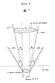
- the three-dimensional objects with an arrangement in which a large number of micro-letters or geometric micro-figures are three-dimensionally arranged spatially in such a manner that these micro-letters or geometric micro-figures compose a three-dimensional image which is easily recognized by naked eyes when taken as a whole, are a cylindrical object as shown in FIG. 1, a spherical object as shown in FIG. 2, a polyhedral object (triangular pyramid in the illustrated case) as shown in FIG. 3, a conical object (concentric object) as shown in FIG. 4, a coil spring-like object (spiral object) as shown in FIG. 5, and a twister-like object (with a billowing axis) as shown in FIG. 6.
- micro-letters of capital letters from A to Z are arranged serially in such a manner as to create a three-dimensional object easily recognizable with naked eyes.
- micro-letters instead of the micro-letters, geometric micro-figures may be used alone or in combination with micro-letters.
- micro-letters or geometric micro-figures are serially arranged, the case of arranging micro-letters or geometric micro-figures concentrically or along outlines of pieces created by cutting a three-dimensional object is better for imparting the three-dimensional effect than the case of spirally arranging micro-letters or geometric micro-figures around a surface of a three-dimensional object just like the cases of FIG. 5 and FIG. 6.
- micro-letters and/or geometric micro-figures used for constituting a three-dimensional object the respective configurations are different, i.e. thick ones (FIG. 4, FIG. 5) and thin ones (FIG. 2, FIG. 3) are mixed, it is extremely difficult to prepare a model of such the three-dimensional object. Therefore, such micro-letters or geometric micro-figures are hardly counterfeited by means of conventional-type hologram in which a model is prepared and photographed with laser beams.
- micro-letters and/or geometric micro-figures are arranged in such a manner that the nearer to the observer the micro-letter or geometric micro-figure is positioned, the larger the size of the micro-letter or geometric micro-figure is. In this arrangement, the sense of depth can be enhanced by perspective effect.
- the three-dimensional object easily recognizable with naked eyes is not limited to the examples shown in FIG. 1 through FIG. 6 and may be any of geometric three-dimensional objects.
- "moiré (wave pattern)" may be employed as the three-dimensional object.
- these micro-letters or geometric micro-figures function as verifying information and other micro-letters or geometric micro-figures, which are located in front of the micro-letters or geometric micro-figures, function as covering object so that the micro-letters or the geometric micro-figures are hidden behind the micro-letters or geometric micro-figures and can not be fully observed in an observation from a predetermined direction, for example from the front direction. However, they may be fully observable from the other direction than the predetermined direction, for example from an oblique direction. In this manner, a three-dimensional micropattern which is more difficult to be counterfeited is achieved, further improving the security.
- micro-letters or geometric micro-figures constituting a three-dimensional object easily recognizable with naked eyes are effective as counterfeit deterrent three-dimensional micropattern when they are recorded with a size difficult to be recognized by naked eyes.
- the size of each micro-letter or geometric micro-figure is not greater than 300 ⁇ m.
- micro-letters or geometric micro-figures are recognized with naked eyes as a whole as one three-dimensional object.
- micro-letters or geometric micro-figures constituting a three-dimensional object are recorded in such a manner that they are reconstructed in different colors.
- the process proposed in the patent reference 2 can be employed.
- the hologram constituting the three-dimensional micropattern of the present invention can be produced by preparing a model of a three-dimensional object as shown in FIG. 1 through FIG. 6 and photographing the model by an ordinary hologram process using two-beam interference.
- the computer generated hologram process as described above is preferable because the ordinary hologram photographing process is difficult to perform for this size.
- the three-dimensional micropattern according to the present invention can be constituted as transfer film or label which can be transferred or attached to documents such as securities and banknotes, such documents being included in the range of the present invention.
- a hologram is composed of a three-dimensional aggregation of a large number of very small micro-letters or geometric micro-figures and is recorded such that the micro-letters or geometric micro-figures are three-dimensionally aggregated to constitute a specific three-dimensional object so as to allow the reconstruction of a three-dimensional image of the three-dimensional object.
- the three-dimensional object easily recognizable with naked eyes can appear when viewed as a whole, the respective micro-letters or geometric micro-figures constituting the three-dimensional object are hardly recognized, thereby facilitating the verification with naked eyes with keeping the counterfeit deterrent effect.
- micro-letters or geometric micro-figures are arranged just as being floating in the space, it is extremely difficult to prepare a model of such configuration. Therefore, such micro-letters or geometric micro-figures are hardly counterfeited by means of conventional-type hologram using two-beam interference in which a model is prepared and photographed with laser beams.
Landscapes
- Physics & Mathematics (AREA)
- General Physics & Mathematics (AREA)
- Business, Economics & Management (AREA)
- Accounting & Taxation (AREA)
- Finance (AREA)
- Credit Cards Or The Like (AREA)
- Holo Graphy (AREA)
- Printing Methods (AREA)
Abstract
Description
- The present invention relates to a three-dimensional micropattern, and in particular, a three-dimensional micropattern with enhanced counterfeit deterrent effect using hologram.
- Conventionally, micro-letters created by printing have been used in the cash vouchers such as securities and banknotes for counterfeit deterrence. However, due to the improvement of color copying machines in resolution and color reproducibility, counterfeit of these cash vouchers are increasing.
- In addition, micro-letters using diffraction gratings have also been practically used for imparting enhanced counterfeit deterrent effect. A security feature using the diffraction grating is often utilized as high level counterfeit deterrence measures because of its high resolution, although it is two-dimensional image. However, these micro-letters using the diffraction grating which have been regarded as high level counterfeit deterrence technique are nowadays increasingly counterfeited, because the patterns recorded in it have come to be detected by microscopic observation, and because of the spread of the diffraction grating image forming devices using laser two-beam interference.
- On the other hand, computer generated holograms (CGHs) have been known. There are generally two processes in the CGH producing technique, of which one is a process in which the object surface is replaced with a set of point light sources or linear light sources, known in the
non-patent reference patent reference 1 and the non-patent reference 3, and others. - The former process of the two, namely replacing the object surface with a set of point light sources or linear light sources, will be described here as a representative process.
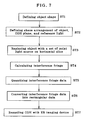
- As an example of CGHs, a binary hologram obtained by recording the intensity distribution of interference fringe, of which reconstructed image has parallax only in horizontal direction, and which is to be observed with white light from above, will be described in outline. Referring to FIG. 7, the shape of the object to be imaged in CGH is defined at step ST1. Then at step ST2, the space arrangements of the object, CGH plane, and reference light are defined. Then at step ST3, the object is divided in the vertical direction with horizontal slices, followed by replacement of the sliced surface with a set of point light sources (linear light sources). Then at step ST4, on the basis of these space arrangements, the intensities of the interference fringe between the light arriving from the point light sources (linear light sources) constituting the object and the reference light are calculated for each sample point defined on the CGH plane, thereby obtaining the interference fringe data. Then at step ST5, the obtained interference fringe data are quantized. After that, at step ST6, the data are converted into a rectangular data for EB imaging, which are recorded at step ST7 on a medium by means of an EB imaging device, thus finally producing CGH.
- In this calculation of the interference fringe, the hidden surface removal process is performed. The hidden surface removal process is a process of making a part, which is hidden by other object in front of it, invisible when an object is observed from a certain viewpoint, whereby the information of overlapping of objects is added to retina image, thus exhibiting a three dimensional effect. In the CGH recording, the hidden surface removal process is performed according to the following procedure.
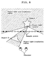
- As shown in FIG. 8, for each point light source constituting the
object 1, the region in which the point light source is hidden byobjects 1, 2 (the hatched area in FIG. 8) is obtained. In the case of CGH which is produced according to the procedure shown in FIG. 7, since theobjects object 1 are hidden byobjects object 1 reconstructed from CGH processed as above, the reconstruction light is not diffracted to the hatched area in FIG. 8, and the region of theobject 1 corresponding to those point light sources becomes invisible because the region becomes behind the image ofobject 2 when an observer drops his viewpoint on that region. - In addition, it is also proposed in the
patent reference 2 that color can be expressed with a CGH, produced by the process in which object surface is replaced by a set of point light sources, by reproducing the CGH with white light. - On the other hand, the inventor has proposed, in Japanese Patent Application No. 2001-365628, "hidden micro-letter" which is recorded in such a manner that a micro-letter providing verifying information is arranged behind a covering object having a size easily recognizable by naked eyes, and the verifying information is hidden by the covering object and is not observable from a predetermined direction, but is observable from the other direction which is different from the predetermined direction, so that the micro-letter is difficult to be detected by counterfeiters. A representative example will be described with reference to FIG. 9. As shown in FIG. 9, verifying information which is a micro-object 11 such as a letter or a figure having such a size as not easily to be recognized by naked eyes, specifically having the largest size not greater than 300 µm, is arranged behind a covering
object 12 having a size larger than micro-object 11 and easily recognizable with naked eyes arranged in front of the micro-object (nearer to the observer relative to the micro-object) , at a position wheremicro-object 11 is covered by the covering object when viewed from the front, so that a viewer E can not observe the verifying information from the front (normal observing direction) , and this arrangement is recorded in aCGH 10. For this end, the hidden surface removal process described above is performed on the set of point light sources expressing the micro-object 11, and the recording is performed in such a manner that the reconstruction light from the micro-object 11 does not diffract to a region at least between theline 21L and theline 21R in FIG. 9. Theline 21L is a line passing the left end of the micro-object 11 and the left end of thecovering object 12, and theline 21R is a line passing the right end of the micro-object 11 and the right end of thecovering object 12, the front direction being included between theline 21L and theline 21R. In addition, theline 22L is a line drawn from the left end of the micro-object 11 toward upper left indicating a boundary of a region to which the reconstruction light from the left end of the micro-object 11 does not diffract, and theline 22R is a line drawn from the right end of the micro-object 11 toward upper right indicating a boundary of a region to which the reconstruction light from the right end of the micro-object 11 does not diffract. - In relation to the above, the right side emission angle γ2 of the object light of micro-object 11 is set larger than the angle β2 which is an angle between the
line 21R connecting the right end of the micro-object 11 and the right end of thecovering object 12 and the front direction, and the left side emission angle γ3 of the object light of micro-object 11 is set larger than the angle β3 which is an angle between theline 21L connecting the left end of the micro-object 11 and the left end of thecovering object 12 and the front direction. Accordingly, as seen from FIG. 9, the angle range in which all or a part of the micro-object 11 is visible is γ2 - β2 + γ3 - β3, while the angle range in which the micro-object is covered is β2 + β3. - In this type of CGH, the presence of verifying information (micro-object 11) is difficult to be noticed because the recorded verifying information is too small to be recognized with naked eyes even under appropriate illumination. In addition, the presence of the verifying information is difficult to be noticed from the front direction which is the normal observation direction, even with the use of magnifying glass or other enlargement device, thus further enhancing the secrecy of verifying information and decreasing the danger of counterfeit.
- In this type of CGH, the verification is performed by irradiating the hologram with appropriate illumination and observing it from a predetermined direction other than the front direction using magnifying glass or other enlargement device to reveal the verifying information (micro-object 11). The verifying
information 11 can be confirmed as it disappears because it becomes behind the coveringobject 12 when the observation position is moved to the front where the observer's direction is the normal observation direction. - Japanese patent No. 3,155,263
- Japanese unexamined patent publication 2000-214751
- "Image Labo" April 1997 (Vol. 8, No. 4) p. 34-37
- 3D-Image Conference '99 Proceedings CD-ROM (June 30-July 1, 1999 at Kogakuin University Shinjuku Campus) "Image Type Binary CGH by EB Imaging (3) -The Enhancement of Three-Dimensional Effect by Hidden Surface removal/Shadowing"
- Research Society of Holographic Display (Optical Society of Japan, Japan Society of Applied Physics), The Third Hodic Conference Proceedings (November 15, 1995, at Nihon University Surugadai Campus, Building No. 1, Meeting Room No. 2) "The Speed Up of Two-Dimensional Image Sequence Generation for Holographic Stereogram"
- As described above, conventional verifying information such as a micro-letter (micropattern) is easily counterfeited and forgery is increasing.
- The present invention is made in order to resolve such problems of the prior art, and it is the object of the present invention to provide a three-dimensional micropattern using a hologram which can not be counterfeited by neither of color copying machine nor diffraction grating image forming device.
- The three-dimensional micropattern of the present invention which can achieve above described object is characterized by comprising a hologram composed of a three-dimensional aggregation of a large number of very small micro-letters or geometric micro-figures, wherein said micro-letters or geometric micro-figures are three-dimensionally aggregated to constitute a specific three-dimensional object so as to allow reconstruction of a three-dimensional image of the three-dimensional object.
- In this connection, it is preferable that the three-dimensional micropattern is recorded as a computer generated hologram. Such computer generated hologram is recorded using a process in which object surface is replaced with a set of point light sources or linear light sources or the holographic stereogram process.
- It is preferable that the size of said each very small micro-letter or geometric micro-figure is not greater than 300 µm.
- Further, it is preferable that the three-dimensional aggregation of said very small micro-letters or geometric micro-figures is recorded so that the aggregation is reconstructed to compose a specific three-dimensional object as a whole when viewed with naked eyes.
- Further, the specific three-dimensional object may be a cylindrical object, a spherical object, a polyhedral object, a conical object, a helical object, a twister-like object.
- Furthermore, the micro-letters or geometric micro-figures three-dimensionally aggregated to form the specific three-dimensional object may be spirally arranged around a surface of the specific three-dimensional object.
- Moreover, the micro-letters or geometric micro-figures three-dimensionally aggregated to form the specific three-dimensional object may be arranged concentrically around a surface of the specific three-dimensional object or along outlines of pieces created by cutting the specific three-dimensional object.
- Among said micro-letters or geometric micro-figures three-dimensionally aggregated to form the specific three-dimensional object, as for the respective configurations, thick ones and thin ones may be mixed.
- Further, the micro-letters or geometric micro-figures positioned on the front side of specific three-dimensional object may be formed to have relatively large size.
- Further, the micro-letters or geometric micro-figures three-dimensionally aggregated to form the specific three-dimensional object may be recorded in such a manner that they are reconstructed in different colors individually or partially when taken as the aggregation.
- In addition, the present invention includes documents on which the three-dimensional micropattern as described above is provided.
- The three-dimensional micropattern of the present invention comprises a hologram which is composed of a three-dimensional aggregation of a large number of very small micro-letters or geometric micro-figures and is recorded such that the micro-letters or geometric micro-figures are three-dimensionally aggregated to constitute a specific three-dimensional object so as to allow the reconstruction of a three-dimensional image of the three-dimensional object. Though the three-dimensional object easily recognizable with naked eyes can appear when viewed as a whole, the respective micro-letters or geometric micro-figures constituting the three-dimensional object are hardly recognized, thereby facilitating the verification with naked eyes with keeping the counterfeit deterrent effect. In addition, since the micro-letters or geometric micro-figures are arranged just as being floating in the space, it is extremely difficult to prepare a model of such configuration. Therefore, such micro-letters or geometric micro-figures are hardly counterfeited by means of an ordinary hologram using two-beam interference in which a model is prepared and photographed with laser beams. Since the other micro-letters or geometric micro-figures located in front function as covering object of the micro-letters or geometric micro-figures located inner side of the three-dimensional object, the existence of the hidden micro-letters or geometric micro-figures is difficult to be noticed from normal observation direction even with the use of enlargement means such as magnifying glass, and the information is impossible to be duplicated with color copying machines and further impossible to be counterfeited with diffraction grating image forming devices, thereby significantly enhancing the counterfeit deterrent effect.
- Still other objects and advantages of the invention will in part be obvious and will in part be apparent from the specification.
- The invention accordingly comprises the features of construction, combinations of elements, and arrangement of parts which will be exemplified in the construction hereinafter set forth, and the scope of the invention will be indicated in the claims.
-
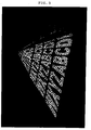
- FIG. 1 is a perspective view showing a cylindrical object as one example of three-dimensional images to be used for the three-dimensional micropattern according to the present invention;
- FIG. 2 is a perspective view showing a spherical object as one example of three-dimensional images to be used for the three-dimensional micropattern according to the present invention;
- FIG. 3 is a perspective view showing a polyhedral object as one example of three-dimensional images to be used for the three-dimensional micropattern according to the present invention;
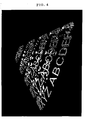
- FIG. 4 is a perspective view showing a conical object as one example of three-dimensional images to be used for the three-dimensional micropattern according to the present invention;
- FIG. 5 is a perspective view showing a coil spring-like object as one example of three-dimensional images to be used for the three-dimensional micropattern according to the present invention;
- FIG. 6 is a perspective view showing a twister-like object as one example of three-dimensional images to be used for the three-dimensional micropattern according to the present invention;
- FIG. 7 is a flow chart schematically showing the procedure of producing CGH according to the process in which object surface is replaced with a set of point light sources or linear light sources;
- FIG. 8 is an illustration for explaining the hidden surface removal process of a CGH recording; and
- FIG. 9 is an illustration for explaining a micro-object, a covering object, and the range of the object light of a CGH comprising verifying information according to the prior application.
-
- Hereinafter, the basic principle and embodiments of the three-dimensional micropattern according to the present invention will be described.
- Because micro-letters or geometric micro-figures are so small that constructions of characters or figures are difficultly observed by naked eyes, enhanced counterfeit deterrent effect can be obtained, but there is a problem that verification by naked eyes is also difficult. To solve this problem, according to the present invention, a large number of micro-letters or geometric micro-figures are three-dimensionally arranged spatially in such a manner that these micro-letters or geometric micro-figures compose a three-dimensional object which is easily recognized by naked eyes when taken as a whole, thereby facilitating the verification with naked eyes with keeping the counterfeit deterrent effect of micro-letters or geometric micro-figures.
- In addition, since the micro-letters or geometric micro-figures are arranged just as being floating in the space, it is extremely difficult to prepare a model of such configuration. Therefore, such micro-letters or geometric micro-figures are hardly counterfeited by means of conventional-type hologram in which a model is prepared and photographed with laser beams.
- Specifically, for example, at step ST1 in FIG. 7 an original image of three-dimensional micro-letters or geometric micro-figures are precisely created by means of a 3D-CAD for computer graphics in such a manner that these three-dimensional micro-letters or geometric micro-figures compose a three-dimensional structure (three-dimensional object) easily recognizable with naked eyes when taken as a whole. Then at step ST2, the space arrangements of the three-dimensional structure, CGH plane, and reference light are defined. Then at step ST3, the three-dimensional micro-letters or geometric micro-figures are replaced with a set of point light sources or linear light sources, and the hidden surface removal process shown in FIG. 8 is performed. At step ST4, on the basis of these space arrangements, interference fringe data is obtained by calculation of intensities of interference fringe between the light coming from each point light source or linear light source constructing the micro-letters or geometric micro-figures as a three-dimensional structure, and a reference light. Then at step ST5, the obtained interference fringe data are quantized. After that, at step ST6, the data are converted into rectangular data for EB imaging. Then at step ST7, the data is recorded on a medium by an EB imaging device. In this manner, the three-dimensional micropattern of the present invention created utilizing the process in which object surface is replaced with a set of point light sources or linear light sources is produced.
- Specific examples of the three-dimensional objects with an arrangement in which a large number of micro-letters or geometric micro-figures are three-dimensionally arranged spatially in such a manner that these micro-letters or geometric micro-figures compose a three-dimensional image which is easily recognized by naked eyes when taken as a whole, are a cylindrical object as shown in FIG. 1, a spherical object as shown in FIG. 2, a polyhedral object (triangular pyramid in the illustrated case) as shown in FIG. 3, a conical object (concentric object) as shown in FIG. 4, a coil spring-like object (spiral object) as shown in FIG. 5, and a twister-like object (with a billowing axis) as shown in FIG. 6.
- In case of a cylindrical object as shown in FIG. 1, very small micro-letters of capital letters from A to Z are arranged serially in alphabetical order along outlines of pieces created by cutting a cylindrical object without the top and bottom, in such a manner as to create a peripheral surface of a cylindrical object as a whole.
- In case of a spherical object as shown in FIG. 2, very small micro-letters of capital letters from A to Z are arranged, relatively roughly in this case, serially in alphabetical order along outlines of pieces created by cutting a sphere, in such a manner as to create a peripheral surface of a sphere as a whole.
- In case of a polyhedral object (tetrahedron) as shown in FIG. 3, very small micro-letters of capital letters from A to Z are arranged serially in alphabetical order along outlines of pieces created by cutting a tetrahedron without its bottom, in such a manner as to create a tetrahedron as a whole. In this case, the nearer to the top of the triangular pyramid, the smaller the size of the micro-letter is.
- Also in case of a conical object (concentric object) as shown in FIG. 4, very small micro-letters of capital letters from A to Z are arranged serially in alphabetical order along outlines of pieces created by cutting a circular cone without its bottom, in such a manner as to create a circular cone as a whole. Also in this case, the nearer to the top of the triangular pyramid, the smaller the size of the micro-letter is.
- In case of a spiral object as shown in FIG. 5, very small micro-letters of capital letters from A to Z are arranged serially and circularly in alphabetical order along a helical line in such a manner as to create a coil spring-like object as a whole.
- In case of a twister-like object as shown in FIG. 6, very small micro-letters of capital letters from A to Z are arranged serially and circularly in alphabetical order along a twister-like line in such a manner as to create a twister-like object as a whole.
- In case of any other object as the three-dimensional object than the shapes as shown in FIG. 1 through FIG. 6, very small micro-letters of capital letters from A to Z are arranged serially in such a manner as to create a three-dimensional object easily recognizable with naked eyes. It should be noted that, instead of the micro-letters, geometric micro-figures may be used alone or in combination with micro-letters.
- When micro-letters or geometric micro-figures are serially arranged, the case of arranging micro-letters or geometric micro-figures concentrically or along outlines of pieces created by cutting a three-dimensional object is better for imparting the three-dimensional effect than the case of spirally arranging micro-letters or geometric micro-figures around a surface of a three-dimensional object just like the cases of FIG. 5 and FIG. 6.
- When among the micro-letters and/or geometric micro-figures used for constituting a three-dimensional object, the respective configurations are different, i.e. thick ones (FIG. 4, FIG. 5) and thin ones (FIG. 2, FIG. 3) are mixed, it is extremely difficult to prepare a model of such the three-dimensional object. Therefore, such micro-letters or geometric micro-figures are hardly counterfeited by means of conventional-type hologram in which a model is prepared and photographed with laser beams.
- It is preferable to arrange the micro-letters and/or geometric micro-figures in such a manner that the nearer to the observer the micro-letter or geometric micro-figure is positioned, the larger the size of the micro-letter or geometric micro-figure is. In this arrangement, the sense of depth can be enhanced by perspective effect.
- The three-dimensional object easily recognizable with naked eyes is not limited to the examples shown in FIG. 1 through FIG. 6 and may be any of geometric three-dimensional objects. For example, "moiré (wave pattern)" may be employed as the three-dimensional object.
- In such constitution, as described with reference to FIG. 9, these micro-letters or geometric micro-figures function as verifying information and other micro-letters or geometric micro-figures, which are located in front of the micro-letters or geometric micro-figures, function as covering object so that the micro-letters or the geometric micro-figures are hidden behind the micro-letters or geometric micro-figures and can not be fully observed in an observation from a predetermined direction, for example from the front direction. However, they may be fully observable from the other direction than the predetermined direction, for example from an oblique direction. In this manner, a three-dimensional micropattern which is more difficult to be counterfeited is achieved, further improving the security.
- The micro-letters or geometric micro-figures constituting a three-dimensional object easily recognizable with naked eyes are effective as counterfeit deterrent three-dimensional micropattern when they are recorded with a size difficult to be recognized by naked eyes. Specifically, it is preferable that the size of each micro-letter or geometric micro-figure is not greater than 300 µm.
- It is preferable that the micro-letters or geometric micro-figures are recognized with naked eyes as a whole as one three-dimensional object.
- Further, it is also preferable that the micro-letters or geometric micro-figures constituting a three-dimensional object are recorded in such a manner that they are reconstructed in different colors. As one of the techniques to achieve this, the process proposed in the
patent reference 2 can be employed. - Further, the hologram constituting the three-dimensional micropattern of the present invention can be produced by preparing a model of a three-dimensional object as shown in FIG. 1 through FIG. 6 and photographing the model by an ordinary hologram process using two-beam interference. However, since the sizes of the micro-letters and geometric micro-figures are not greater than 300 µm, the computer generated hologram process as described above is preferable because the ordinary hologram photographing process is difficult to perform for this size.
- Further, the three-dimensional micropattern according to the present invention can be constituted as transfer film or label which can be transferred or attached to documents such as securities and banknotes, such documents being included in the range of the present invention.
- While the present invention has been described in the above in the context of principle and embodiments thereof, the invention is not limited to these embodiments and various modifications may be made.
- As apparent from the above description, according to the three-dimensional micropattern of the present invention, a hologram is composed of a three-dimensional aggregation of a large number of very small micro-letters or geometric micro-figures and is recorded such that the micro-letters or geometric micro-figures are three-dimensionally aggregated to constitute a specific three-dimensional object so as to allow the reconstruction of a three-dimensional image of the three-dimensional object. Though the three-dimensional object easily recognizable with naked eyes can appear when viewed as a whole, the respective micro-letters or geometric micro-figures constituting the three-dimensional object are hardly recognized, thereby facilitating the verification with naked eyes with keeping the counterfeit deterrent effect. In addition, since the micro-letters or geometric micro-figures are arranged just as being floating in the space, it is extremely difficult to prepare a model of such configuration. Therefore, such micro-letters or geometric micro-figures are hardly counterfeited by means of conventional-type hologram using two-beam interference in which a model is prepared and photographed with laser beams. Since the other micro-letters or geometric micro-figures located in front as covering object of the micro-letters or geometric micro-figures located inner side of the three-dimensional object function, the existence of the hidden micro-letters or geometric micro-figures is difficult to be noticed from normal observation direction even with the use of enlargement means such as magnifying glass, and the information is impossible to be duplicated with color copying machines and further impossible to be counterfeited with diffraction grating image forming devices, thereby significantly enhancing the counterfeit deterrent effect.
Claims (18)
- A three-dimensional micropattern comprising a hologram composed of a three-dimensional aggregation of a large number of very small micro-letters or geometric micro-figures, wherein said micro-letters or geometric micro-figures are three-dimensionally aggregated to constitute a specific three-dimensional object so as to allow reconstruction of a three-dimensional image of the three-dimensional object.
- A three-dimensional micropattern as claimed in claim 1, wherein said three-dimensional micropattern is recorded as a computer generated hologram.
- A three-dimensional micropattern as claimed in claim 2, wherein said three-dimensional micropattern is recorded using a process in which object surface is replaced with a set of point light sources or linear light sources.
- A three-dimensional micropattern as claimed in claim 2, wherein said three-dimensional micropattern is recorded using the holographic stereogram process.
- A three-dimensional micropattern as claimed in any one of claims 1 through 4, wherein the size of said each very small micro-letter or geometric micro-figure is not greater than 300 µm.
- A three-dimensional micropattern as claimed in any one of claims 1 through 5, wherein the three-dimensional aggregation of said very small micro-letters or geometric micro-figures is recorded so that the aggregation is reconstructed to compose a specific three-dimensional object as a whole when viewed with naked eyes.
- A three-dimensional micropattern as claimed in any one of claims 1 through 6, wherein said specific three-dimensional object is a cylindrical object.
- A three-dimensional micropattern as claimed in any one of claims 1 through 6, wherein said specific three-dimensional object is a spherical object.
- A three-dimensional micropattern as claimed in any one of claims 1 through 6, wherein said specific three-dimensional object is a polyhedral object.
- A three-dimensional micropattern as claimed in any one of claims 1 through 6, wherein said specific three-dimensional object is a conical object.
- A three-dimensional micropattern as claimed in any one of claims 1 through 6, wherein said specific three-dimensional object is a helical object.
- A three-dimensional micropattern as claimed in any one of claims 1 through 6, wherein said specific three-dimensional object is a twister-like object.
- A three-dimensional micropattern as claimed in any one of claims 1 through 12, wherein said micro-letters or geometric micro-figures three-dimensionally aggregated to form the specific three-dimensional object are spirally arranged around a surface of the specific three-dimensional object.
- A three-dimensional micropattern as claimed in any one of claims 1 through 12, wherein said micro-letters or geometric micro-figures three-dimensionally aggregated to form the specific three-dimensional object are arranged concentrically around a surface of the specific three-dimensional object or along outlines of pieces created by cutting the specific three-dimensional object.
- A three-dimensional micropattern as claimed in any one of claims 1 through 14, wherein among said micro-letters or geometric micro-figures three-dimensionally aggregated to form the specific three-dimensional object, as for the respective configurations, thick ones and thin ones are mixed.
- A three-dimensional micropattern as claimed in any one of claims 1 through 15, wherein the micro-letters or geometric micro-figures positioned on the front side of specific three-dimensional object are formed to have relatively large size.
- A three-dimensional micropattern as claimed in any one of claims 1 through 16, wherein said micro-letters or geometric micro-figures three-dimensionally aggregated to form the specific three-dimensional object are recorded in such a manner that they are reconstructed in different colors individually or partially when taken as the aggregation.
- A document being provided with a three-dimensional micropattern as claimed in any one of claims 1 through 17.
Applications Claiming Priority (2)
| Application Number | Priority Date | Filing Date | Title |
|---|---|---|---|
| JP2002301296 | 2002-10-16 | ||
| JP2002301296A JP4412576B2 (en) | 2002-10-16 | 2002-10-16 | 3D micro pattern display |
Publications (3)
| Publication Number | Publication Date |
|---|---|
| EP1411398A2 true EP1411398A2 (en) | 2004-04-21 |
| EP1411398A3 EP1411398A3 (en) | 2009-08-26 |
| EP1411398B1 EP1411398B1 (en) | 2013-12-11 |
Family
ID=32040799
Family Applications (1)
| Application Number | Title | Priority Date | Filing Date |
|---|---|---|---|
| EP03022962.9A Expired - Lifetime EP1411398B1 (en) | 2002-10-16 | 2003-10-09 | Micro-patterned three-dimensional hologram and document provided with a micro-patterned three-dimensional hologram |
Country Status (3)
| Country | Link |
|---|---|
| US (1) | US20040076888A1 (en) |
| EP (1) | EP1411398B1 (en) |
| JP (1) | JP4412576B2 (en) |
Cited By (1)
| Publication number | Priority date | Publication date | Assignee | Title |
|---|---|---|---|---|
| GB2495037A (en) * | 2008-07-09 | 2013-03-27 | Dainippon Printing Co Ltd | Hologram for reproducing a ring-shaped character string, and preparation of holograms with parts in front of and behind a holographic recording plane |
Families Citing this family (7)
| Publication number | Priority date | Publication date | Assignee | Title |
|---|---|---|---|---|
| GB0509436D0 (en) * | 2005-05-09 | 2005-06-15 | Smart Holograms Ltd | Method |
| JP4844822B2 (en) * | 2006-04-24 | 2011-12-28 | 大日本印刷株式会社 | Authenticity identification structure |
| JP4831320B2 (en) * | 2006-04-24 | 2011-12-07 | 大日本印刷株式会社 | Authenticity identification structure |
| JP4849252B2 (en) * | 2007-02-13 | 2012-01-11 | 大日本印刷株式会社 | Method for producing security hologram |
| GB0707692D0 (en) * | 2007-04-20 | 2007-05-30 | Smart Holograms Ltd | Methods of making holographic devices |
| JP5282890B2 (en) | 2008-02-01 | 2013-09-04 | 大日本印刷株式会社 | Hologram production method and produced hologram |
| JP2012018324A (en) * | 2010-07-08 | 2012-01-26 | Sony Corp | Multi-viewpoint image recording medium and authenticity determination method |
Family Cites Families (29)
| Publication number | Priority date | Publication date | Assignee | Title |
|---|---|---|---|---|
| US4880286A (en) * | 1987-10-19 | 1989-11-14 | University Of Delaware | Making a holographic optical element using a computer-generated-hologram |
| US5142383A (en) * | 1990-01-25 | 1992-08-25 | American Banknote Holographics, Inc. | Holograms with discontinuous metallization including alpha-numeric shapes |
| GB9025390D0 (en) * | 1990-11-22 | 1991-01-09 | De La Rue Thomas & Co Ltd | Security device |
| US5237433A (en) * | 1992-01-03 | 1993-08-17 | Haines Kenneth A | Methods of hologram construction using computer-processed objects |
| JP3238755B2 (en) * | 1992-08-21 | 2001-12-17 | 富士通株式会社 | Hologram creation and stereoscopic display method and stereoscopic display device |
| JPH06110371A (en) * | 1992-09-30 | 1994-04-22 | Fujitsu Ltd | Stereoscopic display method and device |
| JP3059590B2 (en) * | 1992-09-30 | 2000-07-04 | 富士通株式会社 | Stereoscopic display method and apparatus |
| JP2999637B2 (en) * | 1992-10-14 | 2000-01-17 | 富士通株式会社 | Hologram information creation method |
| US5513019A (en) * | 1993-04-16 | 1996-04-30 | Crown Roll Leaf, Inc. | Semi-transparent reflective layer for a phase hologram |
| JP3778326B2 (en) * | 1997-05-22 | 2006-05-24 | 日本電信電話株式会社 | Computer generated hologram display method, apparatus, and recording medium on which computer generated hologram display program is recorded |
| DE69836360T2 (en) * | 1997-05-22 | 2007-08-23 | Nippon Telegraph And Telephone Corp. | System for displaying computer-controlled holographic images |
| JPH11316308A (en) * | 1998-03-06 | 1999-11-16 | Toppan Printing Co Ltd | Diffraction grating pattern |
| JP3680590B2 (en) * | 1998-10-26 | 2005-08-10 | 凸版印刷株式会社 | Diffraction grating pattern and fabrication method |
| DE19915943A1 (en) * | 1999-04-09 | 2000-10-12 | Ovd Kinegram Ag Zug | Decorative film |
| GB2350961A (en) * | 1999-06-09 | 2000-12-13 | Secr Defence Brit | Determining optical aberrations and compensating therefor in computer generated holograms |
| JP3871837B2 (en) * | 1999-09-30 | 2007-01-24 | 大日本印刷株式会社 | Method for manufacturing hologram recording medium |
| JP2001330717A (en) * | 2000-05-18 | 2001-11-30 | Toppan Printing Co Ltd | Diffraction grating pattern and fabrication method |
| AU6272101A (en) * | 2000-06-09 | 2001-12-17 | Agency Ind Science Techn | Authenticatable printed matter, and method for producing the same |
| JP2002090548A (en) * | 2000-09-14 | 2002-03-27 | Toppan Printing Co Ltd | Display consisting of diffraction grating |
| JP2002157327A (en) * | 2000-11-22 | 2002-05-31 | Kobayashi Kirokushi Co Ltd | Joint issue request system for garbage disposal tickets |
| JP2003228270A (en) * | 2001-11-30 | 2003-08-15 | Dainippon Printing Co Ltd | Hologram with authentication information recorded |
| JP3895166B2 (en) * | 2001-12-17 | 2007-03-22 | 大日本印刷株式会社 | How to create a computer generated hologram |
| JP3964665B2 (en) * | 2001-12-17 | 2007-08-22 | 大日本印刷株式会社 | How to create a computer generated hologram |
| JP4416150B2 (en) * | 2002-10-15 | 2010-02-17 | 大日本印刷株式会社 | Three-dimensional pattern |
| WO2004072739A1 (en) * | 2003-02-12 | 2004-08-26 | Dai Nippon Printing Co., Ltd. | Computer-generated hologram |
| US7580170B2 (en) * | 2003-11-04 | 2009-08-25 | Dai Nippon Printing Co., Ltd. | Fabrication method for a computer-generated hologram or a holographic stereogram in which a three-dimensional object having visualized cross-sectional surfaces is recorded and computer-generated hologram/holographic |
| JP4329999B2 (en) * | 2004-01-07 | 2009-09-09 | 大日本印刷株式会社 | Hologram with authentication information recorded |
| JP4930696B2 (en) * | 2006-09-01 | 2012-05-16 | 大日本印刷株式会社 | Computer-generated hologram and method for producing the same |
| JP5273358B2 (en) * | 2008-07-09 | 2013-08-28 | 大日本印刷株式会社 | Hologram creation method, hologram and security medium using the hologram |
-
2002
- 2002-10-16 JP JP2002301296A patent/JP4412576B2/en not_active Expired - Fee Related
-
2003
- 2003-01-10 US US10/340,853 patent/US20040076888A1/en not_active Abandoned
- 2003-10-09 EP EP03022962.9A patent/EP1411398B1/en not_active Expired - Lifetime
Non-Patent Citations (1)
| Title |
|---|
| T. HAMANO, M. KITAMURA: "Computer-generated holograms for reconstructing multi 3-D images by space-division recording method", PROCEEDINGS OF THE SPIE, vol. 3956, 2000, pages 23 - 32, XP009007446, DOI: doi:10.1117/12.380003 |
Cited By (2)
| Publication number | Priority date | Publication date | Assignee | Title |
|---|---|---|---|---|
| GB2495037A (en) * | 2008-07-09 | 2013-03-27 | Dainippon Printing Co Ltd | Hologram for reproducing a ring-shaped character string, and preparation of holograms with parts in front of and behind a holographic recording plane |
| GB2495037B (en) * | 2008-07-09 | 2013-06-05 | Dainippon Printing Co Ltd | Hologram preparation method, hologram and security method using such hologram |
Also Published As
| Publication number | Publication date |
|---|---|
| US20040076888A1 (en) | 2004-04-22 |
| EP1411398A3 (en) | 2009-08-26 |
| JP2004138688A (en) | 2004-05-13 |
| JP4412576B2 (en) | 2010-02-10 |
| EP1411398B1 (en) | 2013-12-11 |
Similar Documents
| Publication | Publication Date | Title |
|---|---|---|
| EP1296839B1 (en) | Optical device | |
| CA2533094A1 (en) | Security element | |
| CZ2004147A3 (en) | Optical equipment and its manufacturing process | |
| CZ298525B6 (en) | Holographic security device | |
| RU2430836C1 (en) | Multilayer protective element with alternate optical effect and counterfeit-proof document | |
| US20060001937A1 (en) | Optical security device | |
| EP1411398B1 (en) | Micro-patterned three-dimensional hologram and document provided with a micro-patterned three-dimensional hologram | |
| EP1316915B1 (en) | Hologram having authenticating information record therein | |
| JPH11316308A (en) | Diffraction grating pattern | |
| JP5041187B2 (en) | Authentication method hologram production method | |
| JP2000304912A (en) | Diffraction grating pattern | |
| EP1411399B1 (en) | Holographic fine-ribbons pattern | |
| JP2003295744A (en) | Optical information recording medium consisting of computer hologram | |
| US6876472B2 (en) | Optical feature, in particular for documents of value, and a manufacturing method for the later individualization or data storage | |
| EP1819526B1 (en) | Improved hologram | |
| JP4329999B2 (en) | Hologram with authentication information recorded | |
| JP4390250B2 (en) | Hologram with a three-dimensional image recorded in different shapes depending on the viewing direction | |
| JP5029816B2 (en) | Hologram production method | |
| JP2007286256A (en) | Light diffraction structure | |
| JP4784782B2 (en) | Hologram with authentication information recorded | |
| JP4882475B2 (en) | Light diffraction structure | |
| JP4849252B2 (en) | Method for producing security hologram | |
| JP2003295745A (en) | Display using computer generated hologram | |
| JP2023107331A (en) | Glittering moving image pattern forming body and method for producing the same |
Legal Events
| Date | Code | Title | Description |
|---|---|---|---|
| PUAI | Public reference made under article 153(3) epc to a published international application that has entered the european phase |
Free format text: ORIGINAL CODE: 0009012 |
|
| AK | Designated contracting states |
Kind code of ref document: A2 Designated state(s): AT BE BG CH CY CZ DE DK EE ES FI FR GB GR HU IE IT LI LU MC NL PT RO SE SI SK TR |
|
| AX | Request for extension of the european patent |
Extension state: AL LT LV MK |
|
| PUAL | Search report despatched |
Free format text: ORIGINAL CODE: 0009013 |
|
| AK | Designated contracting states |
Kind code of ref document: A3 Designated state(s): AT BE BG CH CY CZ DE DK EE ES FI FR GB GR HU IE IT LI LU MC NL PT RO SE SI SK TR |
|
| AX | Request for extension of the european patent |
Extension state: AL LT LV MK |
|
| 17P | Request for examination filed |
Effective date: 20091026 |
|
| AKX | Designation fees paid |
Designated state(s): DE FR GB |
|
| 17Q | First examination report despatched |
Effective date: 20100924 |
|
| GRAP | Despatch of communication of intention to grant a patent |
Free format text: ORIGINAL CODE: EPIDOSNIGR1 |
|
| INTG | Intention to grant announced |
Effective date: 20130620 |
|
| GRAS | Grant fee paid |
Free format text: ORIGINAL CODE: EPIDOSNIGR3 |
|
| GRAA | (expected) grant |
Free format text: ORIGINAL CODE: 0009210 |
|
| RIN1 | Information on inventor provided before grant (corrected) |
Inventor name: KITAMURA, MITSURU |
|
| AK | Designated contracting states |
Kind code of ref document: B1 Designated state(s): DE FR GB |
|
| REG | Reference to a national code |
Ref country code: GB Ref legal event code: FG4D |
|
| REG | Reference to a national code |
Ref country code: DE Ref legal event code: R096 Ref document number: 60345415 Country of ref document: DE Effective date: 20140206 |
|
| REG | Reference to a national code |
Ref country code: DE Ref legal event code: R097 Ref document number: 60345415 Country of ref document: DE |
|
| PLBE | No opposition filed within time limit |
Free format text: ORIGINAL CODE: 0009261 |
|
| STAA | Information on the status of an ep patent application or granted ep patent |
Free format text: STATUS: NO OPPOSITION FILED WITHIN TIME LIMIT |
|
| 26N | No opposition filed |
Effective date: 20140912 |
|
| REG | Reference to a national code |
Ref country code: DE Ref legal event code: R097 Ref document number: 60345415 Country of ref document: DE Effective date: 20140912 |
|
| REG | Reference to a national code |
Ref country code: FR Ref legal event code: PLFP Year of fee payment: 13 |
|
| REG | Reference to a national code |
Ref country code: FR Ref legal event code: PLFP Year of fee payment: 14 |
|
| REG | Reference to a national code |
Ref country code: FR Ref legal event code: PLFP Year of fee payment: 15 |
|
| REG | Reference to a national code |
Ref country code: FR Ref legal event code: PLFP Year of fee payment: 16 |
|
| PGFP | Annual fee paid to national office [announced via postgrant information from national office to epo] |
Ref country code: GB Payment date: 20201022 Year of fee payment: 18 Ref country code: FR Payment date: 20201021 Year of fee payment: 18 Ref country code: DE Payment date: 20201022 Year of fee payment: 18 |
|
| REG | Reference to a national code |
Ref country code: DE Ref legal event code: R119 Ref document number: 60345415 Country of ref document: DE |
|
| GBPC | Gb: european patent ceased through non-payment of renewal fee |
Effective date: 20211009 |
|
| PG25 | Lapsed in a contracting state [announced via postgrant information from national office to epo] |
Ref country code: GB Free format text: LAPSE BECAUSE OF NON-PAYMENT OF DUE FEES Effective date: 20211009 Ref country code: DE Free format text: LAPSE BECAUSE OF NON-PAYMENT OF DUE FEES Effective date: 20220503 |
|
| PG25 | Lapsed in a contracting state [announced via postgrant information from national office to epo] |
Ref country code: FR Free format text: LAPSE BECAUSE OF NON-PAYMENT OF DUE FEES Effective date: 20211031 |