EP1411334A2 - Residual stress measuring system for optical fibers - Google Patents
Residual stress measuring system for optical fibers Download PDFInfo
- Publication number
- EP1411334A2 EP1411334A2 EP03023691A EP03023691A EP1411334A2 EP 1411334 A2 EP1411334 A2 EP 1411334A2 EP 03023691 A EP03023691 A EP 03023691A EP 03023691 A EP03023691 A EP 03023691A EP 1411334 A2 EP1411334 A2 EP 1411334A2
- Authority
- EP
- European Patent Office
- Prior art keywords
- optical fiber
- residual stress
- light
- holding
- measuring
- Prior art date
- Legal status (The legal status is an assumption and is not a legal conclusion. Google has not performed a legal analysis and makes no representation as to the accuracy of the status listed.)
- Withdrawn
Links
Images


Classifications
-
- G—PHYSICS
- G01—MEASURING; TESTING
- G01L—MEASURING FORCE, STRESS, TORQUE, WORK, MECHANICAL POWER, MECHANICAL EFFICIENCY, OR FLUID PRESSURE
- G01L1/00—Measuring force or stress, in general
-
- G—PHYSICS
- G01—MEASURING; TESTING
- G01L—MEASURING FORCE, STRESS, TORQUE, WORK, MECHANICAL POWER, MECHANICAL EFFICIENCY, OR FLUID PRESSURE
- G01L5/00—Apparatus for, or methods of, measuring force, work, mechanical power, or torque, specially adapted for specific purposes
- G01L5/0047—Apparatus for, or methods of, measuring force, work, mechanical power, or torque, specially adapted for specific purposes measuring forces due to residual stresses
Definitions
- the present invention relates to a system for measuring the residual stress of optical fibers, and more particularly to a system for measuring the residual stress remained in an optical fiber and has an asymmetrical circular stress distribution.
- a residual stress created during the manufacturing stage of drawing an optical fiber remains within the optical fiber.
- This residual stress causes undesirable changes in the refractive index of the fiber and, as a result, increases the light loss in the optical fiber caused by a photoelastic effect.
- the residual stress and its distribution in the optical fiber must be measured accurately and then adjusted accordingly.
- the residual stress in the optical fiber is typically measured using a photoelastic effect, which is a phenomenon in which a refractive index of the fiber is changed along a direction of the stress remaining in a transparent solid medium, such as an optical fiber.
- a photoelastic effect is a phenomenon in which a refractive index of the fiber is changed along a direction of the stress remaining in a transparent solid medium, such as an optical fiber.
- the refractive index of an optical fiber or an optical fiber pre-form changes along the polarized direction, and this change can be observed to measure the stress remained in the fiber.
- Figure 1 is a schematic view of a conventional system used for measuring the residual stress of optical fibers
- Fig. 2 is a diagram showing a phase shift along a light path.
- the conventional residual stress measuring system includes a light source 10 such as a laser, a lens system 30 for aligning the generated light, a polarimeter 50 for polarizing the aligned light, a residual stress measuring section 60, and a light detector 70 for measuring a phase shift of the light generated from a photoelastic effect, which is caused by the residual stress remained in the fiber.
- a light source 10 such as a laser
- a lens system 30 for aligning the generated light
- a polarimeter 50 for polarizing the aligned light
- a residual stress measuring section 60 for measuring a phase shift of the light generated from a photoelastic effect, which is caused by the residual stress remained in the fiber.
- light cast from the light source 10 is reflected by a mirror 20 and passes through the lens system 30, which includes a beam diffuser 31, a lens 32, and a iris 33, and then is converted into a plane wave.
- the plane wave is reflected again by another mirror 40 and enters into the polarimeter 50, which includes a polarizer 51, a wavelength plate 52, and a condenser 53.
- the functions of the mirrors 20 and 40 are to provide a compact design by changing the light path within a given space.
- the polarized light is incident into an optical fiber 62 positioned in the residual stress measuring section 60, which includes a slide glass 61 and a cover glass 63.
- the light passing through the optical fiber has a phase difference resulting from a stress distribution of interior of the optical fiber, and further passes through an objective lens 71 and a polarization analyzer 72.
- a sensor 73 transforms the intensity of light passing through the polarization analyzer 72 into an electrical signal, thereby measuring the residual stress of the optical fiber.
- the residual stress of the optical fiber can be represented by a formula below.
- I ( y ) I o sin 2 ( ⁇ ( y )/2), wherein I o represents the intensity of a background, and ⁇ ( y ) represents the phase shift induced by the residual stress.
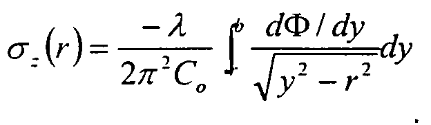
- total residual stress and the photoelastic effect have a profile that can be represented as follows: and wherein C o represents the photoelastic coefficient of the fused silica. Note that these formula are applied under conditions as follows:
- the present invention has been made to solve the above-mentioned problems occurring in the prior art and provides additional advantages, by providing a residual stress measuring system for optical fibers that is capable of measuring residual stress having an asymmetrical circular stress distribution within the optical fiber.
- One embodiment of the present invention relates to a residual stress measuring system for optical fibers.
- the system includes: a light source for generating light used to measure the residual stress; a lens system for converting the generated light into a plane wave; a polarimeter for transforming the converted light to an input polarized light and incident on the input polarized light into the optical fiber; a rotational measuring section for rotating the optical fiber so as to enable the polarized light to transmit through the optical fiber in various directions; and, a detector for detecting the residual stress from a phase shift of the transmitted light, wherein the rotational measuring section rotates the optical fiber, and for measuring residual stress having an asymmetrical circular stress distribution within the optical fiber.
- the rotational measuring section comprises an optical fiber holding section, which includes a slide glass and a cover glass for interposing the optical fiber between both glasses, and a first jig for holding one end of the optical fiber; and, a motor for rotating the first jig holding the optical fiber.
- the optical fiber holding section further comprises a second jig for holding the other end of the optical fiber; and a driving section for transmitting a rotating force from the motor to the first and second jigs uniformly so as to rotate the optical fiber in a controlled manner.
- the present invention is based on the technical principle as described below.
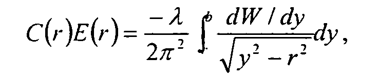
- Equation 1 a difference between the phase shifts of the respective axes induced by the residual stress may be given as the following Equation 1.
- the stress along the longitudinal direction of the optical fiber can be figured out using a rotational measurement device.
- Figure 3 is a schematic view of a residual stress measuring system for optical fibers according to one embodiment of the present invention.
- a residual stress measuring system for optical fibers includes a light source 10, a lens system 30 for aligning the light generated from the light source 10, a polarimeter 50 for polarizing the aligned light output, a rotational measuring section 100 for measuring the residual stress in an optical fiber while rotating the optical fiber, and a light detector 70 for transforming a phase shift induced by the residual stress into an electrical signal.
- the rotational measuring section 100 is configured to measure the residual stress within an optical fiber having an asymmetrical circular stress distribution while rotating the optical fiber. Therefore, the following description will be focused on the rotational measuring section 100.
- Fig. 4 is a schematic view illustrating a rotational measuring section of the inventive residual stress measuring system for optical fibers according to a first embodiment of the present invention.
- the rotational measuring section includes an optical fiber holding section 105 and a motor 106.
- the optical fiber hold section 105 includes a slide glass 101 and a cover glass 103 between which an optical fiber 102 is interposed, and a jig 104 for holding one end of the optical fiber.
- An oil matching the refractive index of the fiber is applied between the slide glass 101 and the cover glass 103. This is to prevent a certain stress from being applied from the exterior as well as to prevent an incident beam from being diffracted during the residual stress measurement of the optical fiber.
- the motor 106 functions to rotate the jig 104, which holds the optical fiber as well as the optical fiber to be measured.
- FIG. 5 is a schematic view of the rotational measuring section according to a second embodiment of the present invention.
- the rotational measuring section includes an optical fiber holding section 206 and a motor 207.
- the rotational measuring section of the second embodiment is different from the first embodiment in that it performs the measurement of the optical fiber while rotating the optical fiber in a vertical position.
- the optical fiber to be measured is dipped into a cell, which is filled with oil 202 to match the refractive index of the fiber.
- the cell 208 includes a tube 203 consisting of a quartz and a cap 204.
- the optical fiber 201 is held by the cap 204 and positioned in the tube 203.
- the optical fiber clamping section 206 includes a jig 205 capable of holding one end of the optical fiber.
- the motor 207 rotates the jig 205 holding the optical fiber 201. Note that the cell 208 is fixed regardless of the rotation of the optical fiber.
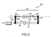
- Fig. 6 is a schematic view of the rotational measuring section of a residual stress measuring system for optical fibers according to a third embodiment of the present invention.
- the rotational measuring section includes an optical fiber holding section 310 and a motor 320.
- the third embodiment is designed to hold both ends of the optical fiber for rotation, so as to prevent an eccentricity or a focusing error that may occur. Further, this arrangement helps to control the rotation of the optical fiber.
- the optical fiber holding section 310 includes a slide glass 301 and a cover glass 303 between which the optical fiber is interposed, and a pair of jigs 304 for holding both ends of the optical fiber.
- the motor 320 further includes a driving section for transmitting the driving force of the motor to both jigs 304 at an equal rotating velocity.
- the driving section comprises a pair of pulleys 305 and belts 306 for rotating both jigs simultaneously, at least one bearing 307, and a rotation shaft 308.
- an oil for matching the refractive index of the fiber is applied between the slide glass 301 and the cover glass 303.
- the oil for matching a refractive index must be viscous enough to rotate the optical fiber without any stress applied to the optical fiber.
- the residual stress measuring system for optical fibers is capable of measuring both the residual stress having an asymmetrical circular stress distribution within the optical fiber as well as the residual stress distribution as the residual stress within the optical fiber is measured during the rotation of the optical fiber.
Landscapes
- Physics & Mathematics (AREA)
- General Physics & Mathematics (AREA)
- Optical Fibers, Optical Fiber Cores, And Optical Fiber Bundles (AREA)
- Investigating Or Analysing Materials By Optical Means (AREA)
- Testing Of Optical Devices Or Fibers (AREA)
Abstract
Description
Claims (7)
- A residual stress measuring system for measuring residual stress in an optical fiber, comprising:a light source for generating light; a lens system for converting the generated light into a plane wave;a polarimeter for transforming the converted light to an input polarized light;a rotational measuring section for rotating the optical fiber to enable the polarized light to transmit through the optical fiber in various directions; and,a detector for detecting the residual stress having an asymmetrical circular stress distribution based on a phase shift of the light transmitted through the optical fiber.
- The system according to claim 1, further comprising at least one mirror for changing a path of the light generated from the light source.
- The system according to claim 1, wherein the rotational measuring section comprises:an optical fiber holding section including a slide glass and a cover glass for interposing the optical fiber therebetween;a first jig for holding one end of the optical fiber; and,a motor for rotating the first jig holding the optical fiber.
- The system according to claim 3, wherein the optical fiber holding section further comprises:a second jig for holding the other end of the optical fiber; and,a driving section for transmitting a rotating force from the motor to the first and second jigs uniformly for rotation of the optical fiber.
- The system according to claim 3, wherein an oil having a substantially similar refractive index of the optical fiber is applied between the slide glass and the cover glass.
- The system according to claim 1, wherein the optical fiber holding section comprises:a jig for holding one upper end of the optical fiber so as to rotate the optical fiber in a vertical orientation; and,a cell, filled with an oil having a substantially similar reflective index of the fiber, for causing the optical fiber to be positioned therein in a vertical orientation.
- The system according to claim 6, wherein the oil has a enough viscosity to rotate the optical fiber without any stress applied to the optical fiber.
Applications Claiming Priority (2)
| Application Number | Priority Date | Filing Date | Title |
|---|---|---|---|
| KR10-2002-0063864A KR100442668B1 (en) | 2002-10-18 | 2002-10-18 | Apparatus for residual stress measuring of optical fiber |
| KR2002063864 | 2002-10-18 |
Publications (2)
| Publication Number | Publication Date |
|---|---|
| EP1411334A2 true EP1411334A2 (en) | 2004-04-21 |
| EP1411334A3 EP1411334A3 (en) | 2004-12-15 |
Family
ID=34256490
Family Applications (1)
| Application Number | Title | Priority Date | Filing Date |
|---|---|---|---|
| EP03023691A Withdrawn EP1411334A3 (en) | 2002-10-18 | 2003-10-17 | Residual stress measuring system for optical fibers |
Country Status (5)
| Country | Link |
|---|---|
| US (1) | US6867853B2 (en) |
| EP (1) | EP1411334A3 (en) |
| JP (1) | JP2004138618A (en) |
| KR (1) | KR100442668B1 (en) |
| CN (1) | CN1260556C (en) |
Families Citing this family (9)
| Publication number | Priority date | Publication date | Assignee | Title |
|---|---|---|---|---|
| WO2006095343A1 (en) * | 2005-03-10 | 2006-09-14 | Anatoly Babchenko | An optical sensor and a method of its use |
| KR100809833B1 (en) * | 2006-01-09 | 2008-03-04 | 광주과학기술원 | Residual stress measuring device and method |
| US7557918B1 (en) | 2006-04-05 | 2009-07-07 | Itt Manufacturing Enterprises, Inc. | Spectral polarimetric image detection and analysis methods and apparatus |
| KR100958185B1 (en) * | 2008-01-14 | 2010-05-14 | 광주과학기술원 | Residual stress measuring device of optical fiber |
| CN201867273U (en) * | 2010-11-17 | 2011-06-15 | 江苏淘镜有限公司 | Checking box for checking polarized lenses |
| CN102507143A (en) * | 2011-09-30 | 2012-06-20 | 清华大学 | Wave plate phase retardation measuring method and optical cement disc |
| CN105283744B (en) | 2013-06-05 | 2018-05-18 | Ev 集团 E·索尔纳有限责任公司 | To determine the measuring device and method of pressure map |
| EP3889118A1 (en) * | 2020-04-03 | 2021-10-06 | Schott AG | Glass tube element with improved quality |
| TWI788873B (en) * | 2021-06-08 | 2023-01-01 | 逢甲大學 | Method and system for measuring interfacial stress and residual stress in multilayer thin films coated on a substrate |
Family Cites Families (8)
| Publication number | Priority date | Publication date | Assignee | Title |
|---|---|---|---|---|
| JPS5815055B2 (en) * | 1978-12-13 | 1983-03-23 | 日本電信電話株式会社 | Inspection method for optical fiber preforms |
| AU585728B2 (en) * | 1986-08-15 | 1989-06-22 | Sumitomo Electric Industries, Ltd. | Method and apparatus of measuring outer diameter and structure of optical fiber |
| GB8819651D0 (en) * | 1988-08-18 | 1988-09-21 | British Telecomm | Orientating optical fibres |
| KR100326302B1 (en) * | 2000-03-13 | 2002-03-08 | 윤종용 | Apparatus and method for measuring residual stress and photoelastic effect of optical fiber |
| KR100332422B1 (en) * | 2000-06-13 | 2002-04-13 | 김효근 | Apparatus for measuring residual stress and refractive index of an optical fiber preform |
| KR100342481B1 (en) * | 2000-08-22 | 2002-06-28 | 윤종용 | Image tracking device and method for transverse measurement of an optical fiber |
| KR100350458B1 (en) * | 2001-01-16 | 2002-08-29 | 삼성전자 주식회사 | Apparatus and method for measuring residual stress and photoelastic effect of optical fiber |
| KR100416979B1 (en) * | 2002-03-18 | 2004-02-05 | 삼성전자주식회사 | Residual stress measuring device for optical fiber |
-
2002
- 2002-10-18 KR KR10-2002-0063864A patent/KR100442668B1/en not_active Expired - Fee Related
-
2003
- 2003-09-09 US US10/658,645 patent/US6867853B2/en not_active Expired - Fee Related
- 2003-10-16 JP JP2003356032A patent/JP2004138618A/en active Pending
- 2003-10-16 CN CNB2003101013759A patent/CN1260556C/en not_active Expired - Fee Related
- 2003-10-17 EP EP03023691A patent/EP1411334A3/en not_active Withdrawn
Also Published As
| Publication number | Publication date |
|---|---|
| US6867853B2 (en) | 2005-03-15 |
| KR100442668B1 (en) | 2004-08-02 |
| EP1411334A3 (en) | 2004-12-15 |
| JP2004138618A (en) | 2004-05-13 |
| CN1260556C (en) | 2006-06-21 |
| KR20040035125A (en) | 2004-04-29 |
| US20040075826A1 (en) | 2004-04-22 |
| CN1497249A (en) | 2004-05-19 |
Similar Documents
| Publication | Publication Date | Title |
|---|---|---|
| KR100326302B1 (en) | Apparatus and method for measuring residual stress and photoelastic effect of optical fiber | |
| US6678433B2 (en) | Apparatus and method for measuring residual stress and photoelastic effect of optical fiber | |
| EP1163498B1 (en) | Improved mode matching for cavity ring-down spectroscopy based upon brewster's angle prism retroreflectors | |
| KR100958185B1 (en) | Residual stress measuring device of optical fiber | |
| US6867853B2 (en) | Residual stress measuring system for optical fibers | |
| CN1206521C (en) | Device for measuring residual stress of optical fibre | |
| JP2004226404A (en) | Optical fiber residual stress measuring device | |
| EP0449193A1 (en) | Optical coupling apparatus for coupling light into a waveguide | |
| US5812255A (en) | Process and device for determining the refractive index of different mediums | |
| CN1239943C (en) | Device for providing polarized light | |
| EP0724147A2 (en) | Apparatus and method for measuring optical anisotropy | |
| KR100992839B1 (en) | Micro Spot Spectroscopy | |
| JP4455126B2 (en) | Optical sensor and optical sensor assembly method | |
| KR100424476B1 (en) | Apparatus for measuring residual stress of optical fiber preform | |
| JPH10232109A (en) | Optical displacement sensor | |
| SU1352202A1 (en) | Device for checking roughness of surface | |
| SU1179170A1 (en) | Polarization refractometer of violated complete internal reflection | |
| Young | Refracted-ray Scanning (refracted Near-field Scanning) for Measuring Index Profils of Optical Fibers | |
| Erofeeva et al. | High-accuracy IR polarimetry of waveguide optical elements | |
| Potter et al. | Multiple mode and multiple source coupling into polymer thin-film waveguides | |
| Murray et al. | A new method for correcting fibre barycentre displacements in high resolution spectroscopy |
Legal Events
| Date | Code | Title | Description |
|---|---|---|---|
| PUAI | Public reference made under article 153(3) epc to a published international application that has entered the european phase |
Free format text: ORIGINAL CODE: 0009012 |
|
| 17P | Request for examination filed |
Effective date: 20031017 |
|
| AK | Designated contracting states |
Kind code of ref document: A2 Designated state(s): AT BE BG CH CY CZ DE DK EE ES FI FR GB GR HU IE IT LI LU MC NL PT RO SE SI SK TR |
|
| AX | Request for extension of the european patent |
Extension state: AL LT LV MK |
|
| PUAL | Search report despatched |
Free format text: ORIGINAL CODE: 0009013 |
|
| AK | Designated contracting states |
Kind code of ref document: A3 Designated state(s): AT BE BG CH CY CZ DE DK EE ES FI FR GB GR HU IE IT LI LU MC NL PT RO SE SI SK TR |
|
| AX | Request for extension of the european patent |
Extension state: AL LT LV MK |
|
| AKX | Designation fees paid |
Designated state(s): DE FR GB |
|
| 17Q | First examination report despatched |
Effective date: 20061127 |
|
| 17Q | First examination report despatched |
Effective date: 20061127 |
|
| STAA | Information on the status of an ep patent application or granted ep patent |
Free format text: STATUS: THE APPLICATION IS DEEMED TO BE WITHDRAWN |
|
| 18D | Application deemed to be withdrawn |
Effective date: 20070816 |