EP1411240A1 - Apparatus and method in connection with a fuel injection system - Google Patents
Apparatus and method in connection with a fuel injection system Download PDFInfo
- Publication number
- EP1411240A1 EP1411240A1 EP20030022601 EP03022601A EP1411240A1 EP 1411240 A1 EP1411240 A1 EP 1411240A1 EP 20030022601 EP20030022601 EP 20030022601 EP 03022601 A EP03022601 A EP 03022601A EP 1411240 A1 EP1411240 A1 EP 1411240A1
- Authority
- EP
- European Patent Office
- Prior art keywords
- fuel
- pump
- pressure boost
- way valve
- temperature
- Prior art date
- Legal status (The legal status is an assumption and is not a legal conclusion. Google has not performed a legal analysis and makes no representation as to the accuracy of the status listed.)
- Granted
Links
- 239000000446 fuel Substances 0.000 title claims abstract description 94
- 238000002347 injection Methods 0.000 title claims abstract description 18
- 239000007924 injection Substances 0.000 title claims abstract description 18
- 238000000034 method Methods 0.000 title claims abstract description 17
- 238000009529 body temperature measurement Methods 0.000 claims abstract description 22
- 238000012544 monitoring process Methods 0.000 claims abstract description 6
- 238000005259 measurement Methods 0.000 claims description 8
- 230000001960 triggered effect Effects 0.000 claims description 4
- 230000007257 malfunction Effects 0.000 description 5
- 239000002828 fuel tank Substances 0.000 description 3
- 239000000243 solution Substances 0.000 description 3
- 238000012546 transfer Methods 0.000 description 2
- 206010010904 Convulsion Diseases 0.000 description 1
- 238000002485 combustion reaction Methods 0.000 description 1
- 230000003247 decreasing effect Effects 0.000 description 1
- 238000009434 installation Methods 0.000 description 1
- 238000012986 modification Methods 0.000 description 1
- 230000004048 modification Effects 0.000 description 1
- 238000005086 pumping Methods 0.000 description 1
Images
Classifications
-
- F—MECHANICAL ENGINEERING; LIGHTING; HEATING; WEAPONS; BLASTING
- F02—COMBUSTION ENGINES; HOT-GAS OR COMBUSTION-PRODUCT ENGINE PLANTS
- F02M—SUPPLYING COMBUSTION ENGINES IN GENERAL WITH COMBUSTIBLE MIXTURES OR CONSTITUENTS THEREOF
- F02M63/00—Other fuel-injection apparatus having pertinent characteristics not provided for in groups F02M39/00 - F02M57/00 or F02M67/00; Details, component parts, or accessories of fuel-injection apparatus, not provided for in, or of interest apart from, the apparatus of groups F02M39/00 - F02M61/00 or F02M67/00; Combination of fuel pump with other devices, e.g. lubricating oil pump
- F02M63/02—Fuel-injection apparatus having several injectors fed by a common pumping element, or having several pumping elements feeding a common injector; Fuel-injection apparatus having provisions for cutting-out pumps, pumping elements, or injectors; Fuel-injection apparatus having provisions for variably interconnecting pumping elements and injectors alternatively
- F02M63/0225—Fuel-injection apparatus having a common rail feeding several injectors ; Means for varying pressure in common rails; Pumps feeding common rails
-
- F—MECHANICAL ENGINEERING; LIGHTING; HEATING; WEAPONS; BLASTING
- F02—COMBUSTION ENGINES; HOT-GAS OR COMBUSTION-PRODUCT ENGINE PLANTS
- F02M—SUPPLYING COMBUSTION ENGINES IN GENERAL WITH COMBUSTIBLE MIXTURES OR CONSTITUENTS THEREOF
- F02M59/00—Pumps specially adapted for fuel-injection and not provided for in groups F02M39/00 -F02M57/00, e.g. rotary cylinder-block type of pumps
- F02M59/44—Details, components parts, or accessories not provided for in, or of interest apart from, the apparatus of groups F02M59/02 - F02M59/42; Pumps having transducers, e.g. to measure displacement of pump rack or piston
-
- F—MECHANICAL ENGINEERING; LIGHTING; HEATING; WEAPONS; BLASTING
- F02—COMBUSTION ENGINES; HOT-GAS OR COMBUSTION-PRODUCT ENGINE PLANTS
- F02M—SUPPLYING COMBUSTION ENGINES IN GENERAL WITH COMBUSTIBLE MIXTURES OR CONSTITUENTS THEREOF
- F02M63/00—Other fuel-injection apparatus having pertinent characteristics not provided for in groups F02M39/00 - F02M57/00 or F02M67/00; Details, component parts, or accessories of fuel-injection apparatus, not provided for in, or of interest apart from, the apparatus of groups F02M39/00 - F02M61/00 or F02M67/00; Combination of fuel pump with other devices, e.g. lubricating oil pump
-
- F—MECHANICAL ENGINEERING; LIGHTING; HEATING; WEAPONS; BLASTING
- F02—COMBUSTION ENGINES; HOT-GAS OR COMBUSTION-PRODUCT ENGINE PLANTS
- F02D—CONTROLLING COMBUSTION ENGINES
- F02D2200/00—Input parameters for engine control
- F02D2200/02—Input parameters for engine control the parameters being related to the engine
- F02D2200/06—Fuel or fuel supply system parameters
- F02D2200/0602—Fuel pressure
-
- F—MECHANICAL ENGINEERING; LIGHTING; HEATING; WEAPONS; BLASTING
- F02—COMBUSTION ENGINES; HOT-GAS OR COMBUSTION-PRODUCT ENGINE PLANTS
- F02D—CONTROLLING COMBUSTION ENGINES
- F02D41/00—Electrical control of supply of combustible mixture or its constituents
- F02D41/30—Controlling fuel injection
- F02D41/38—Controlling fuel injection of the high pressure type
- F02D41/3809—Common rail control systems
- F02D41/3836—Controlling the fuel pressure
-
- F—MECHANICAL ENGINEERING; LIGHTING; HEATING; WEAPONS; BLASTING
- F02—COMBUSTION ENGINES; HOT-GAS OR COMBUSTION-PRODUCT ENGINE PLANTS
- F02M—SUPPLYING COMBUSTION ENGINES IN GENERAL WITH COMBUSTIBLE MIXTURES OR CONSTITUENTS THEREOF
- F02M2200/00—Details of fuel-injection apparatus, not otherwise provided for
- F02M2200/24—Fuel-injection apparatus with sensors
- F02M2200/248—Temperature sensors
Definitions
- the present invention relates to an apparatus in connection with a fuel injection system as defined in the preamble of claim 1, the apparatus comprising a pressure boost pump, in which the pump cylinder and its pump chamber have been arranged in the body part thereof, and a fuel inlet conduit and a fuel outlet conduit in flow connection with the pump chamber, the conduits having a one-way valve, and further a piston apparatus arranged inside the cylinder, the apparatus being movable along its longitudinal axis.
- the invention relates to a method in connection with a fuel injection system according to the preamble of claim 5, the system comprising a pressure boost pump, in which its pump chamber and the pump cylinder have been arranged in the body part thereof, and a fuel inlet conduit and a fuel outlet conduit in flow connection with the pump chamber, the conduits having a one-way valve, and further a piston apparatus arranged inside the cylinder, in which method during the intake stroke of the piston apparatus fuel flows into the pump chamber and during the power stroke of the piston apparatus fuel flows away from the pump chamber via the one-way valve in elevated pressure and temperature.
- a pressure boost pump in which its pump chamber and the pump cylinder have been arranged in the body part thereof, and a fuel inlet conduit and a fuel outlet conduit in flow connection with the pump chamber, the conduits having a one-way valve, and further a piston apparatus arranged inside the cylinder, in which method during the intake stroke of the piston apparatus fuel flows into the pump chamber and during the power stroke of the piston apparatus fuel flows away from the pump chamber via the one-
- Such fuel pressure boost pumps are commonly used in so-called common rail fuel injection systems.
- a common rail solution disclosed in the applicant's previous patent US 6240901 can be mentioned as an example of a solution.
- fuel is fed from the fuel tank to the pressure accumulator by means of a high pressure pump, subsequent to which the fuel is injected into cylinders of the engine by means of injectors.
- a problem with a pump like this is that the lateral forces acting on the piston apparatus of the pump cause wear of the piston apparatus and increase the risk of seizure.
- the apparatus comprises a pressure boost pump, in which the pump cylinder and the pump chamber have been arranged in connection with the body part thereof, and a fuel inlet conduit and a fuel outlet conduit in flow connection with the pump chamber, the conduits having a one-way valve, and further a piston apparatus arranged inside the cylinder, the apparatus being movable along its longitudinal axis.
- the apparatus further comprises a temperature measurement means arranged in the body part for monitoring the operation of the pump.
- An apparatus comprises a number of pressure boost pumps arranged to pump into the pressure accumulator, each of which pumps is provided with a temperature measuring means, and additionally the apparatus comprises an analysis apparatus for comparing the data read from the pressure boost pump temperature measuring means.
- the pressure boost pumps are arranged to pump fuel into a functionally common space.
- the method according to the invention in connection with a fuel injection system comprising a pressure boost pump, in which the pump cylinder and the pump chamber have been arranged in connection with the body part thereof, and a fuel inlet conduit and a fuel outlet conduit in flow connection with the pump chamber, the conduits having a one-way valve, and further a piston apparatus arranged inside the cylinder, in which method during the intake stroke of the piston apparatus fuel flows into the pump chamber and during the power stroke of the piston apparatus fuel flows away from the pump chamber via the one-way valve in elevated pressure and higher temperature and in which method the temperature of the pressure boost pump is measured for monitoring the operation of the pressure boost pump. Defined in more detail this is achieved by means of a temperature measuring means arranged in connection with the pressure boost pump.
- the temperature measuring means is preferably arranged adjacent the pump chamber or the channel connecting pump chamber and the one-way valve of the outlet conduit, or, for example adjacent the one-way valve of the outlet chamber so that temperature increase caused by the above-mentioned malfunction can be detected.
- the rate of change of the measurement data read from the temperature measurement means is compared with the setpoint of the rate of change, and in case the measured rate of change exceeds the setpoint, alarm condition is activated.
- the fuel injection system comprises a number of pressure boost pumps arranged to pump into functionally same space, each of which pumps is provided with at least one temperature measurement means and which injection system further comprises an analysis apparatus for comparing the measurement data read from the temperature measurement means of each pressure boost pump, the temperature of each pressure boost pump is read into the analysis apparatus, in the analysis apparatus the temperature of each pressure boost pump is compared with the temperature of at least one other pressure boost pump and if the temperature difference is larger than the setpoint, alarm condition is activated.
- the temperature of each pressure boost pump is regularly read as the fuel injection system is in operation.
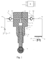
- reference numeral 1 refers to a piston engine fuel pressure boost pump 1 in connection with a fuel injection system.
- the system comprises a source for the fuel, such as a fuel tank 3, into which the fuel pressure boost pump is connected to by means of a channel 4 comprising the transfer pump 4.1, if any.
- the fuel pressure boost pump 1 comprises a body part 5, into which a pump cylinder 6 and the pump chamber 7 are further arranged. Both a fuel inlet conduit 8 and a fuel outlet conduit 9 are arranged in flow connection with the pump chamber 7.
- Both conduits 8, 9 are provided with a one-way valve 8.1, 9.1 so that in normal operation the one-way valve 8.1 of the inlet conduit 8 allows fuel to flow into the pump chamber 7 but does not allow it to flow away from the pump chamber 7, and the one-way valve 9.1 of the outlet valve 9 allows fuel to flow away from the pump chamber 7 but does no allow fuel to flow back to the pump chamber 7.
- the flow is arranged to take place through the channel 7.1 connecting the pump chamber and the one-way valve of the outlet conduit.
- a piston apparatus 2 provided inside the cylinder 6, advantageously arranged freely rotatably around its longitudinal axis.
- the one-way valve 8.1 allows during the suction stroke fuel to pass through it into the pump chamber 7, while during the pressure increase stroke the one-way valve 9.1 allows fuel to pass through it into the common pressure accumulator 11.
- the pressure of the common pressure accumulator is higher, so the pressure of the fuel pump chamber will have to increase sufficiently for the one-way valve 9.1 to open.
- the channel 4 transferring fuel from the fuel tank is connected with the inlet conduit 8 from which fuel can flow unidirectionally through the one-way valve 8.1 to the pump chamber 7. From there, fuel is conveyed unidirectionally via the one-way valve 9.1 and the outlet conduit 9 to the fuel transfer channel 10 connecting the pressure boost pump 1 and the common pressure accumulator. From the common pressure accumulator 11, fuel is transferred to the engine combustion chamber 13 by means of an injector nozzle 12. Further, the piston apparatus is functionally connected to the camshaft 14 or a corresponding arrangement for causing its reciprocating movement.
- the apparatus comprises a temperature measurement means 15, arranged in the body part 5 of the fuel pressure boost pump 1, the measurement means being connected to analysis apparatus 16. Measurement data is regularly read from the temperature measurement means 15 into the analysis apparatus 16 as the engine is in operation. Temperature measurement setpoint data is stored in the analysis apparatus 16 or elsewhere to be used by it, the data being used in monitoring the operation of the fuel pressure boost pump.
- the apparatus according to figure 1 comprises one fuel pressure boost pump 1, whereby the rate of change of the measurement data read from the temperature measurement means 15 is compared with the setpoint of the rate of change, stored in the analysis apparatus 16 or available to it somewhere else in the system. If the measured rate of change is larger than the setpoint, predefined alarm procedures are triggered. Such procedures can include, for example alarming the control room of the installation and/or storing the alarm information into the control system.
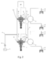
- the fuel injection system comprises at least fuel pressure boost pumps 1 arranged to pump into the common pressure accumulator 11.
- the common pressure accumulators 11 are in flow connection with each other by means of channel 11'. This allows the fluctuation of the fuel pressure to be decreased.
- Each fuel pressure boost pump 1 is provided with at least one temperature measurement means 15.
- the fuel injection system comprises in this case as well an analysis apparatus 16. It is electrically connected to each of the temperature measurement means 15 of fuel pressure boost pumps 1. Measurement data is continuously read into the analysis apparatus 16 from each of the temperature measurement apparatuses 15 and in the analysis apparatus the temperature of each separate fuel pressure boost pump 1 is compared to that of at least one other fuel pressure boost pump. If the temperature difference is larger than the setpoint stored in the analysis apparatus or somewhere else to be used by it, alarm condition is triggered.
- the sequential temperature measurement data does not necessarily have to be stored, because a fault in the one-way valve 9.1 can be detected by comparing the temperatures read from various locations.
- the analysis apparatus described here can, for example, be the engine control computer or the like.
Landscapes
- Engineering & Computer Science (AREA)
- Chemical & Material Sciences (AREA)
- Combustion & Propulsion (AREA)
- Mechanical Engineering (AREA)
- General Engineering & Computer Science (AREA)
- Fuel-Injection Apparatus (AREA)
- Electrical Control Of Air Or Fuel Supplied To Internal-Combustion Engine (AREA)
- Combined Controls Of Internal Combustion Engines (AREA)
Abstract
Description
- The present invention relates to an apparatus in connection with a fuel injection system as defined in the preamble of
claim 1, the apparatus comprising a pressure boost pump, in which the pump cylinder and its pump chamber have been arranged in the body part thereof, and a fuel inlet conduit and a fuel outlet conduit in flow connection with the pump chamber, the conduits having a one-way valve, and further a piston apparatus arranged inside the cylinder, the apparatus being movable along its longitudinal axis. - In addition, the invention relates to a method in connection with a fuel injection system according to the preamble of
claim 5, the system comprising a pressure boost pump, in which its pump chamber and the pump cylinder have been arranged in the body part thereof, and a fuel inlet conduit and a fuel outlet conduit in flow connection with the pump chamber, the conduits having a one-way valve, and further a piston apparatus arranged inside the cylinder, in which method during the intake stroke of the piston apparatus fuel flows into the pump chamber and during the power stroke of the piston apparatus fuel flows away from the pump chamber via the one-way valve in elevated pressure and temperature. - Such fuel pressure boost pumps are commonly used in so-called common rail fuel injection systems. A common rail solution disclosed in the applicant's previous patent US 6240901 can be mentioned as an example of a solution. In this solution, fuel is fed from the fuel tank to the pressure accumulator by means of a high pressure pump, subsequent to which the fuel is injected into cylinders of the engine by means of injectors.
- A problem with a pump like this is that the lateral forces acting on the piston apparatus of the pump cause wear of the piston apparatus and increase the risk of seizure.
- It is an aim of the present invention to produce an apparatus in connection with a fuel injection system minimizing the problems associated with prior art. It is an especial aim of the invention to produce an apparatus and method in connection with a so-called common rail system for efficiently detecting pressure boost pump malfunctions.
- The aims of the invention are mainly achieved as disclosed in the appended
claims - The apparatus comprises a pressure boost pump, in which the pump cylinder and the pump chamber have been arranged in connection with the body part thereof, and a fuel inlet conduit and a fuel outlet conduit in flow connection with the pump chamber, the conduits having a one-way valve, and further a piston apparatus arranged inside the cylinder, the apparatus being movable along its longitudinal axis. The apparatus further comprises a temperature measurement means arranged in the body part for monitoring the operation of the pump.
- An apparatus according to an embodiment of the invention comprises a number of pressure boost pumps arranged to pump into the pressure accumulator, each of which pumps is provided with a temperature measuring means, and additionally the apparatus comprises an analysis apparatus for comparing the data read from the pressure boost pump temperature measuring means. Advantageously the pressure boost pumps are arranged to pump fuel into a functionally common space.
- The method according to the invention in connection with a fuel injection system comprising a pressure boost pump, in which the pump cylinder and the pump chamber have been arranged in connection with the body part thereof, and a fuel inlet conduit and a fuel outlet conduit in flow connection with the pump chamber, the conduits having a one-way valve, and further a piston apparatus arranged inside the cylinder, in which method during the intake stroke of the piston apparatus fuel flows into the pump chamber and during the power stroke of the piston apparatus fuel flows away from the pump chamber via the one-way valve in elevated pressure and higher temperature and in which method the temperature of the pressure boost pump is measured for monitoring the operation of the pressure boost pump. Defined in more detail this is achieved by means of a temperature measuring means arranged in connection with the pressure boost pump.
- Typically the part in which the malfunction occurs is the one-way valve of the outlet conduit, which in a malfunction allows fuel to move to pump chamber and again back out therefrom. Therefore, the temperature measuring means is preferably arranged adjacent the pump chamber or the channel connecting pump chamber and the one-way valve of the outlet conduit, or, for example adjacent the one-way valve of the outlet chamber so that temperature increase caused by the above-mentioned malfunction can be detected.
- In the case the system only comprises one pressure boost pump, the rate of change of the measurement data read from the temperature measurement means is compared with the setpoint of the rate of change, and in case the measured rate of change exceeds the setpoint, alarm condition is activated.
- If the fuel injection system comprises a number of pressure boost pumps arranged to pump into functionally same space, each of which pumps is provided with at least one temperature measurement means and which injection system further comprises an analysis apparatus for comparing the measurement data read from the temperature measurement means of each pressure boost pump, the temperature of each pressure boost pump is read into the analysis apparatus, in the analysis apparatus the temperature of each pressure boost pump is compared with the temperature of at least one other pressure boost pump and if the temperature difference is larger than the setpoint, alarm condition is activated.
- The temperature of each pressure boost pump is regularly read as the fuel injection system is in operation.
- In the following the invention is described by way of example and with reference to the appended drawings, of which
- figure 1 shows an exemplary embodiment of the fuel pressure boost pump; and
- figure 2 shows another exemplary embodiment of the fuel pressure boost pump.
-
- In the appended drawings,
reference numeral 1 refers to a piston engine fuelpressure boost pump 1 in connection with a fuel injection system. The system comprises a source for the fuel, such as afuel tank 3, into which the fuel pressure boost pump is connected to by means of achannel 4 comprising the transfer pump 4.1, if any. The fuelpressure boost pump 1 comprises abody part 5, into which apump cylinder 6 and thepump chamber 7 are further arranged. Both afuel inlet conduit 8 and afuel outlet conduit 9 are arranged in flow connection with thepump chamber 7. Bothconduits inlet conduit 8 allows fuel to flow into thepump chamber 7 but does not allow it to flow away from thepump chamber 7, and the one-way valve 9.1 of theoutlet valve 9 allows fuel to flow away from thepump chamber 7 but does no allow fuel to flow back to thepump chamber 7. The flow is arranged to take place through the channel 7.1 connecting the pump chamber and the one-way valve of the outlet conduit. In a fuelpressure boost pump 1 according to the invention there further is apiston apparatus 2 provided inside thecylinder 6, advantageously arranged freely rotatably around its longitudinal axis. During normal operation, as the piston reciprocates in the direction of its longitudinal axis, the one-way valve 8.1 allows during the suction stroke fuel to pass through it into thepump chamber 7, while during the pressure increase stroke the one-way valve 9.1 allows fuel to pass through it into thecommon pressure accumulator 11. The pressure of the common pressure accumulator is higher, so the pressure of the fuel pump chamber will have to increase sufficiently for the one-way valve 9.1 to open. - The
channel 4 transferring fuel from the fuel tank is connected with theinlet conduit 8 from which fuel can flow unidirectionally through the one-way valve 8.1 to thepump chamber 7. From there, fuel is conveyed unidirectionally via the one-way valve 9.1 and theoutlet conduit 9 to thefuel transfer channel 10 connecting thepressure boost pump 1 and the common pressure accumulator. From thecommon pressure accumulator 11, fuel is transferred to theengine combustion chamber 13 by means of aninjector nozzle 12. Further, the piston apparatus is functionally connected to thecamshaft 14 or a corresponding arrangement for causing its reciprocating movement. - The apparatus comprises a temperature measurement means 15, arranged in the
body part 5 of the fuelpressure boost pump 1, the measurement means being connected toanalysis apparatus 16. Measurement data is regularly read from the temperature measurement means 15 into theanalysis apparatus 16 as the engine is in operation. Temperature measurement setpoint data is stored in theanalysis apparatus 16 or elsewhere to be used by it, the data being used in monitoring the operation of the fuel pressure boost pump. - During normal operation fuel flows during the intake stroke of the piston apparatus via the one-way valve 8.1 of the
fuel inlet conduit 2 into thepump chamber 7, and during the power stroke of the piston apparatus fuel flows via the one-way valve 9.1 of theoutlet conduit 9 in elevated temperature and pressure away from the pump chamber into thecommon pressure accumulator 11. During this operation the temperature of the fuel pressure boost pump is measured by means of a temperature measurement means 15 to monitor the operation of the one-way valve 9.1 of theoutlet conduit 9. The monitoring is based on the observation that if the one-way valve 9.1 malfunctions and it allows fuel to flow back to thepump chamber 7, whereby the same fuel is pumped many times back and forth, this sequential pumping back and forth will cause a quick increase of temperature. This can be detected by means of the analysingapparatus 16 and necessary actions can be taken. - The apparatus according to figure 1 comprises one fuel
pressure boost pump 1, whereby the rate of change of the measurement data read from the temperature measurement means 15 is compared with the setpoint of the rate of change, stored in theanalysis apparatus 16 or available to it somewhere else in the system. If the measured rate of change is larger than the setpoint, predefined alarm procedures are triggered. Such procedures can include, for example alarming the control room of the installation and/or storing the alarm information into the control system. - In the embodiment shown in figure 2 the fuel injection system comprises at least fuel
pressure boost pumps 1 arranged to pump into thecommon pressure accumulator 11. Thecommon pressure accumulators 11 are in flow connection with each other by means of channel 11'. This allows the fluctuation of the fuel pressure to be decreased. Each fuelpressure boost pump 1 is provided with at least one temperature measurement means 15. The fuel injection system comprises in this case as well ananalysis apparatus 16. It is electrically connected to each of the temperature measurement means 15 of fuelpressure boost pumps 1. Measurement data is continuously read into theanalysis apparatus 16 from each of thetemperature measurement apparatuses 15 and in the analysis apparatus the temperature of each separate fuelpressure boost pump 1 is compared to that of at least one other fuel pressure boost pump. If the temperature difference is larger than the setpoint stored in the analysis apparatus or somewhere else to be used by it, alarm condition is triggered. - In a system as that shown in figure 2, comprising a number of fuel pressure boost pumps, the sequential temperature measurement data does not necessarily have to be stored, because a fault in the one-way valve 9.1 can be detected by comparing the temperatures read from various locations. The analysis apparatus described here can, for example, be the engine control computer or the like.
- The invention is not limited to the embodiments described here, but a number of modifications thereof can be conceived of within the scope of the appended claims.
Claims (8)
- An apparatus in connection with a fuel injection system, the apparatus comprising a fuel pressure boost pump (1), in which a pump cylinder (6) and a pump chamber (7) have been arranged in the body part (5) of the pump, and a fuel inlet conduit (8) and a fuel outlet conduit (9) in flow connection with the pump chamber, the conduits having a one-way valve (8.1, 9.1), and further a piston apparatus (2) arranged inside the cylinder (6), the piston apparatus being movable along its longitudinal axis, characterized in that the apparatus further comprises a temperature measurement means (15) arranged in the body part (5).
- An apparatus according to claim 1, characterized in that it comprises a number of fuel pressure boost pumps (1), each of which is provided with a temperature measurement means (15), and the apparatus further comprises an analysis apparatus (16) for comparing the measurement data read from the temperature measurement means (15) of the fuel pressure boost pumps (16).
- An apparatus according to claim 2, characterized in that the fuel pressure boost pumps (1) are arranged to pump fuel into a functionally common space (11, 11').
- An apparatus according to any of the preceding claims, characterized in that the temperature measurement means (15) is arranged adjacent the pump chamber (7) or the channel (7.1) connecting the pump chamber and the one-way valve of the outlet conduit or adjacent the one-way valve (9.1) of the outlet conduit (9).
- A method in connection with a fuel injection system comprising a pressure boost pump (1), in which the pump cylinder (6) and the pump chamber (7) have been arranged in connection with the body part (5) thereof, and a fuel inlet conduit (8) and a fuel outlet conduit (9) in flow connection with the pump chamber, the conduits having a one-way valve (8.1, 9.1), and further a piston apparatus (2) arranged inside the cylinder (6), in which method fuel flows into the pump chamber via the one-way valve (8.1) of the inlet conduit (2) during the intake stroke of the piston apparatus and during the power stroke of the piston apparatus fuel flows away from the pump chamber via the one-way valve (9.1) of the outlet conduit (9) in elevated pressure and temperature, characterized in that the temperature of the pressure boost pump is measured by means of a temperature measuring means for monitoring the operation of one-way valve (9.1) of the outlet conduit (9).
- A method according to claim 3, characterized in that the rate of change of the data read from the temperature measurement means (15) is compared with the setpoint of the rate of change and in case the measured rate of change exceeds the setpoint value, an alarm condition is triggered.
- A method according to claim 3, characterized in that it is accomplished in connection with a fuel injection system, the system comprising a number of fuel pressure boost pumps (1) arranged to pump into a functionally common space (11, 11'), each of which pumps is provided with at least one temperature measurement means (15) and which fuel injection system further comprises an analysis apparatus (16) for comparing the measurement data read from each of the temperature measurement means (15) of each fuel pressure boost pump (1), in which method the temperature of each fuel pressure boost pump (1) is read into the analysis apparatus (16), in which analysis apparatus (16) the temperature of each fuel pressure boost pump (1) is compared with that of at least one other fuel pressure boost pump (1) and if the temperature difference exceeds the setpoint, alarm procedure is triggered.
- A method according to claim 5, characterized in that the temperature of each fuel pressure boost pump (1) is read at regular interval when the fuel injection system is in operation.
Applications Claiming Priority (2)
| Application Number | Priority Date | Filing Date | Title |
|---|---|---|---|
| FI20021841 | 2002-10-16 | ||
| FI20021841A FI117350B (en) | 2002-10-16 | 2002-10-16 | Device and method of fuel feed system |
Publications (2)
| Publication Number | Publication Date |
|---|---|
| EP1411240A1 true EP1411240A1 (en) | 2004-04-21 |
| EP1411240B1 EP1411240B1 (en) | 2005-12-28 |
Family
ID=8564765
Family Applications (1)
| Application Number | Title | Priority Date | Filing Date |
|---|---|---|---|
| EP03022601A Expired - Lifetime EP1411240B1 (en) | 2002-10-16 | 2003-10-06 | Apparatus and method in connection with a fuel injection system |
Country Status (6)
| Country | Link |
|---|---|
| US (1) | US6845752B2 (en) |
| EP (1) | EP1411240B1 (en) |
| JP (2) | JP4464652B2 (en) |
| AT (1) | ATE314576T1 (en) |
| DE (1) | DE60302976T2 (en) |
| FI (1) | FI117350B (en) |
Cited By (2)
| Publication number | Priority date | Publication date | Assignee | Title |
|---|---|---|---|---|
| WO2008057032A1 (en) * | 2006-11-10 | 2008-05-15 | Scania Cv Ab (Publ) | Fuel pump device |
| WO2013037542A1 (en) * | 2011-09-14 | 2013-03-21 | Robert Bosch Gmbh | High-pressure fuel pump for injection system |
Families Citing this family (3)
| Publication number | Priority date | Publication date | Assignee | Title |
|---|---|---|---|---|
| FI117350B (en) * | 2002-10-16 | 2006-09-15 | Waertsilae Finland Oy | Device and method of fuel feed system |
| DE102007044001B4 (en) * | 2007-09-14 | 2019-08-01 | Robert Bosch Gmbh | Method for controlling a fuel injection system of an internal combustion engine |
| EP2302194B1 (en) * | 2009-07-08 | 2012-09-19 | Delphi Technologies Holding S.à.r.l. | A pump unit |
Citations (4)
| Publication number | Priority date | Publication date | Assignee | Title |
|---|---|---|---|---|
| JPS61212661A (en) * | 1985-03-19 | 1986-09-20 | Nippon Denso Co Ltd | Distributor type fuel injection pump |
| EP0316581A1 (en) * | 1987-11-19 | 1989-05-24 | Robert Bosch Gmbh | Fuel injection pump for internal-combustion engines |
| EP1036923A2 (en) * | 1999-03-17 | 2000-09-20 | Toyota Jidosha Kabushiki Kaisha | Method of determining abnormality in high-pressure fuel injection device |
| WO2001040638A2 (en) * | 1999-12-01 | 2001-06-07 | Robert Bosch Gmbh | Fuel supply system for an internal combustion engine |
Family Cites Families (15)
| Publication number | Priority date | Publication date | Assignee | Title |
|---|---|---|---|---|
| JPS58133440A (en) * | 1982-02-03 | 1983-08-09 | Nissan Motor Co Ltd | Electronically controlled fuel injection pump |
| DE3602713A1 (en) * | 1986-01-30 | 1987-08-06 | Bosch Gmbh Robert | FUEL INJECTION PUMP FOR INTERNAL COMBUSTION ENGINES |
| US6102000A (en) * | 1993-11-02 | 2000-08-15 | Toyota Jidosha Kabushiki Kaisha | Fuel injection apparatus for engine |
| US5509392A (en) * | 1995-04-28 | 1996-04-23 | Schmitz; John J. | Anti-vapor lock fuel system |
| JP3744036B2 (en) * | 1995-10-31 | 2006-02-08 | 日産自動車株式会社 | Diesel engine fuel property detection device and control device |
| US5868175A (en) * | 1996-06-28 | 1999-02-09 | Franklin Electric Co., Inc. | Apparatus for recovery of fuel vapor |
| DE19746563A1 (en) * | 1997-10-22 | 1999-04-29 | Bosch Gmbh Robert | Fuel injection system for IC engine |
| JPH11166445A (en) * | 1997-12-04 | 1999-06-22 | Yamaha Motor Co Ltd | Engine abnormal combustion control method |
| FI107831B (en) | 1998-05-20 | 2001-10-15 | Waertsilae Tech Oy Ab | Fuel Supply System |
| WO2001007779A1 (en) * | 1999-07-23 | 2001-02-01 | Hitachi, Ltd. | High-pressure fuel pump and fuel feed method |
| JP2002235633A (en) | 2001-02-08 | 2002-08-23 | Denso Corp | Distribution type fuel injection pump |
| DE10114969A1 (en) * | 2001-03-27 | 2002-10-10 | Leybold Vakuum Gmbh | Turbo molecular pump |
| DE10158950C2 (en) * | 2001-12-03 | 2003-10-02 | Bosch Gmbh Robert | Method, computer program, control and regulating device for operating an internal combustion engine, and internal combustion engine |
| US6908289B2 (en) * | 2002-05-31 | 2005-06-21 | Hydro-Aire, Inc. | Fuel pump with automatic shutoff |
| FI117350B (en) * | 2002-10-16 | 2006-09-15 | Waertsilae Finland Oy | Device and method of fuel feed system |
-
2002
- 2002-10-16 FI FI20021841A patent/FI117350B/en not_active IP Right Cessation
-
2003
- 2003-10-06 AT AT03022601T patent/ATE314576T1/en active
- 2003-10-06 EP EP03022601A patent/EP1411240B1/en not_active Expired - Lifetime
- 2003-10-06 DE DE60302976T patent/DE60302976T2/en not_active Expired - Lifetime
- 2003-10-15 JP JP2003355068A patent/JP4464652B2/en not_active Expired - Lifetime
- 2003-10-15 US US10/687,097 patent/US6845752B2/en not_active Expired - Lifetime
-
2009
- 2009-11-09 JP JP2009255711A patent/JP4966365B2/en not_active Expired - Lifetime
Patent Citations (4)
| Publication number | Priority date | Publication date | Assignee | Title |
|---|---|---|---|---|
| JPS61212661A (en) * | 1985-03-19 | 1986-09-20 | Nippon Denso Co Ltd | Distributor type fuel injection pump |
| EP0316581A1 (en) * | 1987-11-19 | 1989-05-24 | Robert Bosch Gmbh | Fuel injection pump for internal-combustion engines |
| EP1036923A2 (en) * | 1999-03-17 | 2000-09-20 | Toyota Jidosha Kabushiki Kaisha | Method of determining abnormality in high-pressure fuel injection device |
| WO2001040638A2 (en) * | 1999-12-01 | 2001-06-07 | Robert Bosch Gmbh | Fuel supply system for an internal combustion engine |
Non-Patent Citations (1)
| Title |
|---|
| PATENT ABSTRACTS OF JAPAN vol. 011, no. 050 (M - 562) 17 February 1987 (1987-02-17) * |
Cited By (3)
| Publication number | Priority date | Publication date | Assignee | Title |
|---|---|---|---|---|
| WO2008057032A1 (en) * | 2006-11-10 | 2008-05-15 | Scania Cv Ab (Publ) | Fuel pump device |
| US8167577B2 (en) | 2006-11-10 | 2012-05-01 | Scania Cv Ab (Publ) | Fuel pump device |
| WO2013037542A1 (en) * | 2011-09-14 | 2013-03-21 | Robert Bosch Gmbh | High-pressure fuel pump for injection system |
Also Published As
| Publication number | Publication date |
|---|---|
| FI20021841L (en) | 2004-04-17 |
| EP1411240B1 (en) | 2005-12-28 |
| FI117350B (en) | 2006-09-15 |
| JP4464652B2 (en) | 2010-05-19 |
| US6845752B2 (en) | 2005-01-25 |
| FI20021841A0 (en) | 2002-10-16 |
| JP4966365B2 (en) | 2012-07-04 |
| DE60302976T2 (en) | 2006-07-06 |
| ATE314576T1 (en) | 2006-01-15 |
| DE60302976D1 (en) | 2006-02-02 |
| US20040079336A1 (en) | 2004-04-29 |
| JP2010031875A (en) | 2010-02-12 |
| JP2004138063A (en) | 2004-05-13 |
Similar Documents
| Publication | Publication Date | Title |
|---|---|---|
| US7913496B2 (en) | Apparatus and method for pumping a cryogenic fluid from a storage vessel and diagnosing cryogenic pump performance | |
| JP5730387B2 (en) | Fuel system for internal combustion engines | |
| CN103370529B (en) | Fuel injection system | |
| EP1847706A1 (en) | Fuel supply system for diesel engine | |
| US10041432B2 (en) | Fuel system having pump prognostic functionality | |
| US20080041331A1 (en) | System for dynamically detecting fuel leakage | |
| KR101720380B1 (en) | Pipe connector and fuel injection system | |
| CN103502622A (en) | Fuel injection control system for internal combustion engine | |
| JP4966365B2 (en) | Apparatus and method associated with a fuel injection system | |
| US7100574B2 (en) | Common rail type fuel injection system | |
| JP5278290B2 (en) | Failure diagnosis device for fuel injection system | |
| JP4787208B2 (en) | LIQUID GAS FUEL SUPPLY DEVICE AND METHOD FOR DRIVING HIGH PRESSURE PUMP | |
| WO2007097052A1 (en) | Fuel injection system for internal combustion engine | |
| JP2004225630A (en) | Accumulation type fuel injection system | |
| CN103038465B (en) | For the central system of lubrication of cylinder lubrication | |
| CN104675548B (en) | Engine controller | |
| JP2016142149A (en) | Abnormality diagnosis device | |
| JP2004084538A (en) | Common rail fuel injection system | |
| WO2020071087A1 (en) | Water injection pump | |
| JP2703103B2 (en) | High pressure oil generator for internal combustion engines | |
| JP4640387B2 (en) | High pressure pump and fuel supply device for internal combustion engine | |
| JP2006342800A (en) | Internal combustion engine | |
| JP2002266719A (en) | Accumulator distribution type fuel injection pump |
Legal Events
| Date | Code | Title | Description |
|---|---|---|---|
| PUAI | Public reference made under article 153(3) epc to a published international application that has entered the european phase |
Free format text: ORIGINAL CODE: 0009012 |
|
| AK | Designated contracting states |
Kind code of ref document: A1 Designated state(s): AT BE BG CH CY CZ DE DK EE ES FI FR GB GR HU IE IT LI LU MC NL PT RO SE SI SK TR |
|
| AX | Request for extension of the european patent |
Extension state: AL LT LV MK |
|
| 17P | Request for examination filed |
Effective date: 20040728 |
|
| 17Q | First examination report despatched |
Effective date: 20040923 |
|
| AKX | Designation fees paid |
Designated state(s): AT BE BG CH CY CZ DE DK EE ES FI FR GB GR HU IE IT LI LU MC NL PT RO SE SI SK TR |
|
| GRAP | Despatch of communication of intention to grant a patent |
Free format text: ORIGINAL CODE: EPIDOSNIGR1 |
|
| GRAS | Grant fee paid |
Free format text: ORIGINAL CODE: EPIDOSNIGR3 |
|
| GRAA | (expected) grant |
Free format text: ORIGINAL CODE: 0009210 |
|
| AK | Designated contracting states |
Kind code of ref document: B1 Designated state(s): AT BE BG CH CY CZ DE DK EE ES FI FR GB GR HU IE IT LI LU MC NL PT RO SE SI SK TR |
|
| PG25 | Lapsed in a contracting state [announced via postgrant information from national office to epo] |
Ref country code: IT Free format text: LAPSE BECAUSE OF FAILURE TO SUBMIT A TRANSLATION OF THE DESCRIPTION OR TO PAY THE FEE WITHIN THE PRESCRIBED TIME-LIMIT;WARNING: LAPSES OF ITALIAN PATENTS WITH EFFECTIVE DATE BEFORE 2007 MAY HAVE OCCURRED AT ANY TIME BEFORE 2007. THE CORRECT EFFECTIVE DATE MAY BE DIFFERENT FROM THE ONE RECORDED. Effective date: 20051228 Ref country code: NL Free format text: LAPSE BECAUSE OF FAILURE TO SUBMIT A TRANSLATION OF THE DESCRIPTION OR TO PAY THE FEE WITHIN THE PRESCRIBED TIME-LIMIT Effective date: 20051228 Ref country code: CZ Free format text: LAPSE BECAUSE OF FAILURE TO SUBMIT A TRANSLATION OF THE DESCRIPTION OR TO PAY THE FEE WITHIN THE PRESCRIBED TIME-LIMIT Effective date: 20051228 Ref country code: SI Free format text: LAPSE BECAUSE OF FAILURE TO SUBMIT A TRANSLATION OF THE DESCRIPTION OR TO PAY THE FEE WITHIN THE PRESCRIBED TIME-LIMIT Effective date: 20051228 Ref country code: BE Free format text: LAPSE BECAUSE OF FAILURE TO SUBMIT A TRANSLATION OF THE DESCRIPTION OR TO PAY THE FEE WITHIN THE PRESCRIBED TIME-LIMIT Effective date: 20051228 Ref country code: SK Free format text: LAPSE BECAUSE OF FAILURE TO SUBMIT A TRANSLATION OF THE DESCRIPTION OR TO PAY THE FEE WITHIN THE PRESCRIBED TIME-LIMIT Effective date: 20051228 Ref country code: FI Free format text: LAPSE BECAUSE OF FAILURE TO SUBMIT A TRANSLATION OF THE DESCRIPTION OR TO PAY THE FEE WITHIN THE PRESCRIBED TIME-LIMIT Effective date: 20051228 Ref country code: RO Free format text: LAPSE BECAUSE OF FAILURE TO SUBMIT A TRANSLATION OF THE DESCRIPTION OR TO PAY THE FEE WITHIN THE PRESCRIBED TIME-LIMIT Effective date: 20051228 |
|
| REG | Reference to a national code |
Ref country code: GB Ref legal event code: FG4D |
|
| REG | Reference to a national code |
Ref country code: CH Ref legal event code: EP Ref country code: CH Ref legal event code: NV Representative=s name: ABACUS PATENTANWAELTE KLOCKE SPAETH BARTH |
|
| REG | Reference to a national code |
Ref country code: IE Ref legal event code: FG4D |
|
| REF | Corresponds to: |
Ref document number: 60302976 Country of ref document: DE Date of ref document: 20060202 Kind code of ref document: P |
|
| PG25 | Lapsed in a contracting state [announced via postgrant information from national office to epo] |
Ref country code: GR Free format text: LAPSE BECAUSE OF FAILURE TO SUBMIT A TRANSLATION OF THE DESCRIPTION OR TO PAY THE FEE WITHIN THE PRESCRIBED TIME-LIMIT Effective date: 20060328 Ref country code: SE Free format text: LAPSE BECAUSE OF FAILURE TO SUBMIT A TRANSLATION OF THE DESCRIPTION OR TO PAY THE FEE WITHIN THE PRESCRIBED TIME-LIMIT Effective date: 20060328 Ref country code: BG Free format text: LAPSE BECAUSE OF FAILURE TO SUBMIT A TRANSLATION OF THE DESCRIPTION OR TO PAY THE FEE WITHIN THE PRESCRIBED TIME-LIMIT Effective date: 20060328 Ref country code: DK Free format text: LAPSE BECAUSE OF FAILURE TO SUBMIT A TRANSLATION OF THE DESCRIPTION OR TO PAY THE FEE WITHIN THE PRESCRIBED TIME-LIMIT Effective date: 20060328 |
|
| PG25 | Lapsed in a contracting state [announced via postgrant information from national office to epo] |
Ref country code: ES Free format text: LAPSE BECAUSE OF FAILURE TO SUBMIT A TRANSLATION OF THE DESCRIPTION OR TO PAY THE FEE WITHIN THE PRESCRIBED TIME-LIMIT Effective date: 20060408 |
|
| PG25 | Lapsed in a contracting state [announced via postgrant information from national office to epo] |
Ref country code: PT Free format text: LAPSE BECAUSE OF FAILURE TO SUBMIT A TRANSLATION OF THE DESCRIPTION OR TO PAY THE FEE WITHIN THE PRESCRIBED TIME-LIMIT Effective date: 20060529 |
|
| NLV1 | Nl: lapsed or annulled due to failure to fulfill the requirements of art. 29p and 29m of the patents act | ||
| PG25 | Lapsed in a contracting state [announced via postgrant information from national office to epo] |
Ref country code: HU Free format text: LAPSE BECAUSE OF FAILURE TO SUBMIT A TRANSLATION OF THE DESCRIPTION OR TO PAY THE FEE WITHIN THE PRESCRIBED TIME-LIMIT Effective date: 20060629 |
|
| PG25 | Lapsed in a contracting state [announced via postgrant information from national office to epo] |
Ref country code: IE Free format text: LAPSE BECAUSE OF NON-PAYMENT OF DUE FEES Effective date: 20061006 |
|
| PG25 | Lapsed in a contracting state [announced via postgrant information from national office to epo] |
Ref country code: MC Free format text: LAPSE BECAUSE OF NON-PAYMENT OF DUE FEES Effective date: 20061031 |
|
| PLBE | No opposition filed within time limit |
Free format text: ORIGINAL CODE: 0009261 |
|
| STAA | Information on the status of an ep patent application or granted ep patent |
Free format text: STATUS: NO OPPOSITION FILED WITHIN TIME LIMIT |
|
| 26N | No opposition filed |
Effective date: 20060929 |
|
| EN | Fr: translation not filed | ||
| REG | Reference to a national code |
Ref country code: IE Ref legal event code: MM4A |
|
| PG25 | Lapsed in a contracting state [announced via postgrant information from national office to epo] |
Ref country code: FR Free format text: LAPSE BECAUSE OF FAILURE TO SUBMIT A TRANSLATION OF THE DESCRIPTION OR TO PAY THE FEE WITHIN THE PRESCRIBED TIME-LIMIT Effective date: 20070216 |
|
| PG25 | Lapsed in a contracting state [announced via postgrant information from national office to epo] |
Ref country code: EE Free format text: LAPSE BECAUSE OF FAILURE TO SUBMIT A TRANSLATION OF THE DESCRIPTION OR TO PAY THE FEE WITHIN THE PRESCRIBED TIME-LIMIT Effective date: 20051228 |
|
| PG25 | Lapsed in a contracting state [announced via postgrant information from national office to epo] |
Ref country code: TR Free format text: LAPSE BECAUSE OF FAILURE TO SUBMIT A TRANSLATION OF THE DESCRIPTION OR TO PAY THE FEE WITHIN THE PRESCRIBED TIME-LIMIT Effective date: 20051228 Ref country code: LU Free format text: LAPSE BECAUSE OF NON-PAYMENT OF DUE FEES Effective date: 20061006 |
|
| PG25 | Lapsed in a contracting state [announced via postgrant information from national office to epo] |
Ref country code: FR Free format text: LAPSE BECAUSE OF FAILURE TO SUBMIT A TRANSLATION OF THE DESCRIPTION OR TO PAY THE FEE WITHIN THE PRESCRIBED TIME-LIMIT Effective date: 20051228 Ref country code: CY Free format text: LAPSE BECAUSE OF FAILURE TO SUBMIT A TRANSLATION OF THE DESCRIPTION OR TO PAY THE FEE WITHIN THE PRESCRIBED TIME-LIMIT Effective date: 20051228 |
|
| REG | Reference to a national code |
Ref country code: DE Ref legal event code: R082 Ref document number: 60302976 Country of ref document: DE Representative=s name: GRAF GLUECK KRITZENBERGER, DE Ref country code: DE Ref legal event code: R082 Ref document number: 60302976 Country of ref document: DE Representative=s name: GLUECK - KRITZENBERGER PATENTANWAELTE PARTGMBB, DE |
|
| PGFP | Annual fee paid to national office [announced via postgrant information from national office to epo] |
Ref country code: AT Payment date: 20171024 Year of fee payment: 15 Ref country code: CH Payment date: 20171019 Year of fee payment: 15 |
|
| REG | Reference to a national code |
Ref country code: CH Ref legal event code: PL |
|
| REG | Reference to a national code |
Ref country code: AT Ref legal event code: MM01 Ref document number: 314576 Country of ref document: AT Kind code of ref document: T Effective date: 20181006 |
|
| PG25 | Lapsed in a contracting state [announced via postgrant information from national office to epo] |
Ref country code: CH Free format text: LAPSE BECAUSE OF NON-PAYMENT OF DUE FEES Effective date: 20181031 Ref country code: LI Free format text: LAPSE BECAUSE OF NON-PAYMENT OF DUE FEES Effective date: 20181031 |
|
| PG25 | Lapsed in a contracting state [announced via postgrant information from national office to epo] |
Ref country code: AT Free format text: LAPSE BECAUSE OF NON-PAYMENT OF DUE FEES Effective date: 20181006 |
|
| PGFP | Annual fee paid to national office [announced via postgrant information from national office to epo] |
Ref country code: IT Payment date: 20221026 Year of fee payment: 20 Ref country code: GB Payment date: 20221019 Year of fee payment: 20 Ref country code: DE Payment date: 20221019 Year of fee payment: 20 |
|
| REG | Reference to a national code |
Ref country code: DE Ref legal event code: R071 Ref document number: 60302976 Country of ref document: DE |
|
| REG | Reference to a national code |
Ref country code: GB Ref legal event code: PE20 Expiry date: 20231005 |
|
| PG25 | Lapsed in a contracting state [announced via postgrant information from national office to epo] |
Ref country code: GB Free format text: LAPSE BECAUSE OF EXPIRATION OF PROTECTION Effective date: 20231005 |
|
| PG25 | Lapsed in a contracting state [announced via postgrant information from national office to epo] |
Ref country code: GB Free format text: LAPSE BECAUSE OF EXPIRATION OF PROTECTION Effective date: 20231005 |