EP1411010A2 - Paper sheet detection apparatus - Google Patents
Paper sheet detection apparatus Download PDFInfo
- Publication number
- EP1411010A2 EP1411010A2 EP03020948A EP03020948A EP1411010A2 EP 1411010 A2 EP1411010 A2 EP 1411010A2 EP 03020948 A EP03020948 A EP 03020948A EP 03020948 A EP03020948 A EP 03020948A EP 1411010 A2 EP1411010 A2 EP 1411010A2
- Authority
- EP
- European Patent Office
- Prior art keywords
- paper sheet
- pair
- guide members
- guide
- conveying
- Prior art date
- Legal status (The legal status is an assumption and is not a legal conclusion. Google has not performed a legal analysis and makes no representation as to the accuracy of the status listed.)
- Granted
Links
- 238000001514 detection method Methods 0.000 title claims abstract description 101
- 230000003068 static effect Effects 0.000 claims description 12
- 238000007689 inspection Methods 0.000 claims description 8
- 230000004048 modification Effects 0.000 description 14
- 238000012986 modification Methods 0.000 description 14
- 238000012545 processing Methods 0.000 description 11
- 238000010586 diagram Methods 0.000 description 10
- 238000005452 bending Methods 0.000 description 6
- 230000007423 decrease Effects 0.000 description 6
- 230000008901 benefit Effects 0.000 description 5
- 230000003247 decreasing effect Effects 0.000 description 3
- 230000007246 mechanism Effects 0.000 description 3
- 239000002390 adhesive tape Substances 0.000 description 2
- 238000004140 cleaning Methods 0.000 description 2
- 239000000428 dust Substances 0.000 description 2
- 239000012530 fluid Substances 0.000 description 2
- 238000012856 packing Methods 0.000 description 2
- 230000037303 wrinkles Effects 0.000 description 2
- 241000743339 Agrostis Species 0.000 description 1
- 229910000838 Al alloy Inorganic materials 0.000 description 1
- OKTJSMMVPCPJKN-UHFFFAOYSA-N Carbon Chemical compound [C] OKTJSMMVPCPJKN-UHFFFAOYSA-N 0.000 description 1
- ATJFFYVFTNAWJD-UHFFFAOYSA-N Tin Chemical compound [Sn] ATJFFYVFTNAWJD-UHFFFAOYSA-N 0.000 description 1
- 230000009471 action Effects 0.000 description 1
- 238000009530 blood pressure measurement Methods 0.000 description 1
- 229910052799 carbon Inorganic materials 0.000 description 1
- 230000008859 change Effects 0.000 description 1
- 239000002131 composite material Substances 0.000 description 1
- 230000000593 degrading effect Effects 0.000 description 1
- 230000006866 deterioration Effects 0.000 description 1
- 229910003460 diamond Inorganic materials 0.000 description 1
- 239000010432 diamond Substances 0.000 description 1
- 239000011521 glass Substances 0.000 description 1
- 238000012423 maintenance Methods 0.000 description 1
- 239000000463 material Substances 0.000 description 1
- 239000011159 matrix material Substances 0.000 description 1
- 239000000203 mixture Substances 0.000 description 1
- 230000003287 optical effect Effects 0.000 description 1
- 230000035945 sensitivity Effects 0.000 description 1
- 230000000007 visual effect Effects 0.000 description 1
Images







Classifications
-
- B—PERFORMING OPERATIONS; TRANSPORTING
- B65—CONVEYING; PACKING; STORING; HANDLING THIN OR FILAMENTARY MATERIAL
- B65H—HANDLING THIN OR FILAMENTARY MATERIAL, e.g. SHEETS, WEBS, CABLES
- B65H7/00—Controlling article feeding, separating, pile-advancing, or associated apparatus, to take account of incorrect feeding, absence of articles, or presence of faulty articles
- B65H7/02—Controlling article feeding, separating, pile-advancing, or associated apparatus, to take account of incorrect feeding, absence of articles, or presence of faulty articles by feelers or detectors
-
- B—PERFORMING OPERATIONS; TRANSPORTING
- B65—CONVEYING; PACKING; STORING; HANDLING THIN OR FILAMENTARY MATERIAL
- B65H—HANDLING THIN OR FILAMENTARY MATERIAL, e.g. SHEETS, WEBS, CABLES
- B65H5/00—Feeding articles separated from piles; Feeding articles to machines
- B65H5/36—Article guides or smoothers, e.g. movable in operation
- B65H5/38—Article guides or smoothers, e.g. movable in operation immovable in operation
-
- B—PERFORMING OPERATIONS; TRANSPORTING
- B65—CONVEYING; PACKING; STORING; HANDLING THIN OR FILAMENTARY MATERIAL
- B65H—HANDLING THIN OR FILAMENTARY MATERIAL, e.g. SHEETS, WEBS, CABLES
- B65H2406/00—Means using fluid
- B65H2406/10—Means using fluid made only for exhausting gaseous medium
- B65H2406/11—Means using fluid made only for exhausting gaseous medium producing fluidised bed
-
- B—PERFORMING OPERATIONS; TRANSPORTING
- B65—CONVEYING; PACKING; STORING; HANDLING THIN OR FILAMENTARY MATERIAL
- B65H—HANDLING THIN OR FILAMENTARY MATERIAL, e.g. SHEETS, WEBS, CABLES
- B65H2511/00—Dimensions; Position; Numbers; Identification; Occurrences
- B65H2511/50—Occurence
- B65H2511/51—Presence
-
- B—PERFORMING OPERATIONS; TRANSPORTING
- B65—CONVEYING; PACKING; STORING; HANDLING THIN OR FILAMENTARY MATERIAL
- B65H—HANDLING THIN OR FILAMENTARY MATERIAL, e.g. SHEETS, WEBS, CABLES
- B65H2701/00—Handled material; Storage means
- B65H2701/10—Handled articles or webs
- B65H2701/19—Specific article or web
- B65H2701/1912—Banknotes, bills and cheques or the like
Definitions
- the present invention relates to a paper sheet detection apparatus which detects the magnetic ink printed on paper sheets such as securities.
- One type of paper sheet detection apparatus detects a paper sheet by holding and conveying it to a detection sensor by a conveying belt, for example, or by holding and conveying a paper sheet to a detection sensor by a pair of conveying rollers.
- Another type of paper sheet detection apparatus detects a paper sheet by placing a paper sheet on a conveying belt with holes and conveying it to a suction chamber. A paper sheet conveyed to a suction chamber is sucked onto a conveying belt by sucking out air through the holes in the conveying belt, and the whole non-sucked side of the sucked paper sheet is detected.
- the present invention has been made taking notice of the above-mentioned circumstances. It is an object of the present invention to provide a paper sheet detection apparatus, which prevents flapping and bending of a paper sheet and obtain an accurate detection signal of a detection device.
- a paper sheet detection apparatus comprising a conveying device which conveys a paper sheet along a conveying surface; a detection device which is provided opposite to the conveying surface and detects a paper sheet conveyed by the conveying device; a guide device which is provided in at least the paper sheet take-in side of the detection device and formed with a pair of guide members disposed opposite to each other at both sides of the conveying surface; a nozzle which is provided in the opposite surface of the pair of guide members; and a gas supply device which supplies compressed gas to the pair of guide members and ejects the gas from the nozzle between the pair of guide members.
- a paper sheet detection apparatus comprising a conveying device which conveys a paper sheet along a conveying surface; a detection device which is provided opposite to the conveying surface and detects a paper sheet conveyed by the conveying device; a guide device which is provided in at least the paper sheet take-in side of the detection device and formed with a pair of guide members disposed opposite to each other at both side of the conveying surface; a nozzle which is provided in the opposite surface of the pair of guide members; an energizing device which elastically energizes one of the pair of guide members toward the other guide member; and a gas supply device which generates a clearance between the pair of guide members by moving one of the pair of guide members against the energizing force of the energizing device, by supplying compressed gas to the pair of guide members and ejecting the gas from the nozzle between the pair of guide members.
- FIG. 1 is a top plan view showing a paper sheet detection apparatus according to a first embodiment of the present invention.
- FIG. 2 is a front view of the paper sheet detection apparatus.
- FIG. 3 is a side view of the paper sheet detection apparatus.
- the detection apparatus has conveying belts 1, 2 as a conveying device, which holds both sides of a paper sheet P and conveys the paper sheet in the arrow C direction.
- the conveying belts 1 and 2 are laid over rollers 4a, 4b, and run.
- the conveying belts 1, 2 are formed with upper and lower belt parts 1a, 1b and 2a, 2b disposed opposite to each other, and hold and convey a paper sheet P by these upper and lower belt parts 1a, 1b and 2a, 2b.
- a sensor guide 3 is provided as a guide device between the conveying belts 1 and 2.
- the sensor guide 3 is formed with upper and lower guide members 5, 6 disposed opposite to each other with a predetermined interval through the conveying surface of a paper sheet P.
- the upper and lower guide members 5, 6 are fixedly held by a base 11 through holders 8, 9.
- a detection sensor 12 is provided as a detection device.
- the detection sensor 12 is fixedly supported by a holder 9 of the lower guide member 6, for example.
- Air tubes 14 and 15 are connected to the upper and lower guide members 5 and 6, respectively, to supply compressed fluid, for example, compressed air.
- the upper guide member 5 is supported by the upper holder 8 through a universal joint 17 and a shaft 18.
- the shaft 18 is movable in the length direction, but the rotation is restricted.
- a coil spring 20 is inserted between the holder 8 and the universal joint 17, and the shaft 18 is inserted into the coil spring 20.
- the upper guide member 5 is pressed to the lower guide member 6 by the emerging force of the coil spring 20, to be parallel along the upper surface of the lower guide member 6 by the action of the universal joint 17.
- FIG. 4A is a sectional view showing the sensor guide 3 taken along the arrow line D-D in FIG. 1.
- the upper and lower guide members 5 and 6 have nozzle boxes 21a and 21b, respectively.
- the nozzle boxes 21a and 21b are closed by lids 22a and 22b, respectively, through a packing material not shown in the drawing.
- the air tubes 14 and 15 are connected to the lids 22a and 22b through tube fittings 23a and 23b.
- Guide plates 25a and 25b are fixed to the end faces of the paper sheet take-in sides of the nozzle boxes 21a and 21b.
- nozzles 27a and 27b are formed to eject compressed air.
- FIG. 4B is a block diagram showing a gas supply device 64, which supplies the upper and lower guide members 5 and 6 with compressed air as compressed gas.
- a reference numeral 65 denotes a compressed air source.
- the compressed air source 65 is connected with a manifold 68 through a pressure reducing device 66 and a solenoid valve 67 that is opened and closed by an electric signal.
- the manifold 68 is connected with the upper and lower guide members 5 and 6 through the air tubes 14 and 15.
- a paper sheet P is held and conveyed by conveying belts 1 and 2, and at the same time the compressed air source 65 is operated.
- compressed air is fed out, reduced the pressure in the pressure reducing device 66, and supplied to the upper and lower guide members 5 and 6, respectively, through the manifold 68 and the air tubes 14 and 15.
- the supplied compressed air is ejected from the nozzles 27a and 27b, respectively.
- an air layer which is determined by the pressure and flow rate of the compressed air, the atmospheric pressure, and the pressing force of the coil spring 20, is formed between the opposite surfaces of the upper and lower guide members 5 and 6, and the guide members 5 and 6 are balanced by repulsing each other.
- a paper sheet P is fed between the upper and lower guide members 5, 6, and an air layer is formed between the upper and lower guide members 5, 6 and both sides of the paper sheet P, respectively.
- the paper sheet P is floated from the upper and lower guide members 5, 6, and guided and conveyed to the detection sensor 12 in the non-contacted state with the both sides pressed and held by the air layers, and the information of the paper sheet is detected.
- the upper guide member 5 is pressed by the coil spring 20, and the paper sheet P is kept flat without being flapped and bent.
- the paper sheet P is floated from the upper and lower guide members 5, 6, and guided and conveyed in the non-contacted state with the both sides pressed and held by the air layers, and the paper sheet P is kept flat without being flapped and bent caused by the vibration of the conveying belts 1, 2.
- the detection sensor 12 can detect a signal in the state with no flapping and bending of the paper sheet P, increasing the detection accuracy.
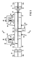
- FIG. 5 shows a paper sheet detection apparatus according to a second embodiment of the present invention.
- FIG. 6 is a front view of the apparatus, and
- FIG. 7 is a side view of the apparatus.
- a reference numeral 31 denotes a first conveying device, which holds and conveys a paper sheet P.
- a first sensor guide 32 as a guide device, a detection sensor 33 as a detection device, a second sensor guide 34 as a guide device, and a second conveying device 35 are sequentially disposed along the paper sheet P conveying direction.
- the first and second conveying devices 31, 35 are composed of upper conveying belts 31a, 31a, 35a, 35a disposed in parallel along the paper P with a predetermined interval, and lower conveying belts 31b, 31b, 35b, 35b provided under the upper conveying belts 31a, 31a, 35a, 35a, so as to hold and convey the paper sheet P in the arrow B direction.
- the upper conveying belts 31a, 31a, 35a, 35a and lower conveying belts 31b, 31b, 35b, 35b are laid over rollers 36, 36, 37, 37.
- the rollers 36, 36, 37, 37 are supported by a base 41 through support shafts 38, 39.
- the first and second sensor guides 32, 34 are formed with upper and lower guide members 50, 51 and 53, 54, disposed opposite to each other through a conveying surface H to convey a paper sheet P, and placed before and after the detection sensor 33.
- the upper guide member 50 of the first sensor guide 32 is supported by a holder 46 through a universal joint 43, a support bar 44 and a support pin 45, and rotatable around the support pin 45.
- the holder 46 is fixed to the base 41.
- the support bar 44 is pressed by a push screw 48 and a spring member 49, pressing the upper guide member 50 to the lower guide member 51.
- the lower guide member 51 is fixedly provided on the base 41 through a holder 47.
- the second sensor guide 34 is configured in the say way as the first sensor guide 32.
- the same reference numerals are given to the same parts, and the description will be omitted.
- FIG. 8 is a sectional view showing the upper and lower guide members 50, 51 and 53, 54, which constitute the first and second sensor guides 32, 34.
- the upper and lower guide members 50, 51 and 53, 54 are configured in the same way, and only the upper guide member 50 will be explained as a representative.
- the upper guide member 50 has a nozzle box 56.
- the nozzle box 56 is closed by a lid 57 that is fixed through a not-shown packing member.
- the lid 57 is connected with an air tube 58 through a tube fitting 59.
- the nozzle box 56 is formed with many nozzles for ejecting compressed air, as described later.
- nozzles aj , ... en are provided as a matrix of a, b, c, d, e rows and j, k, l, m, n columns, as shown in FIG. 9, and grooves ab, bc, cd, de, jk, kl, lm, mn are provided surrounding the nozzles aj, ... en.
- the distance between the nozzles of the j and n columns disposed in the outermost side is set larger than the width dimension of a paper sheet P.
- the grooves jk, kl, lm, mn are formed in parallel along the paper sheet P conveying direction, and the grooves ab, bc, cd, de are formed in parallel along the direction orthogonal to the paper sheet P conveying direction.
- Compressed air is supplied to the nozzles aj, ... en from a cavity 63 between the nozzle box 56 and the lid 57.
- the grooves ab, dc, cd, de are shaped like a saw tooth, so that the corners of the grooves ab, dc, cd, de do not disturb the conveyance of the paper sheet P in the arrow D direction.
- the nozzles aj, ... en and the grooves ab, bc, cd, de formed on the opposite surface 61 of the upper and lower guide members 50, 51, 53, 54 are provided at the opposite positions, but the nozzles aj, ... en may be provided at the position shifted from the opposite positions.
- FIG. 10 is a sectional view taken along the E-E line in FIG. 9, showing the positional relationship between the guide members 50 (53), 51 (54) and the paper sheet P, and the flow state of compressed air by an arrow.
- FIG. 11 is a block diagram showing a gas supply device for supplying compressed air to the upper and lower guide members 50, 51 and 53, 54, which constitute the first and second sensor guides 32, 34.
- the gas supply device is configured in the same way as the gas supply device 64 shown in FIG. 4B, and the same reference numerals are give to the same parts.
- a reference numeral 65 denotes a compressed air source.
- the compressed air source 65 is connected with a manifold 68 through a pressure reducing device 66 and a solenoid valve 67 that is opened and closed by an electric signal.
- the manifold 68 is connected with the upper and lower guide members 50, 51 and 53, 54 through the air tube 58.
- the compressed air source 65 is operated. By the operation of the compressed air source 65, compressed air is supplied.
- the compressed air is reduced in the pressure reducing device 66, and supplied to the upper and lower guide members 50, 51 and 53, 54 through the solenoid valve 67, the manifold 68 and the air tube 58, as shown in FIG. 10.
- the compressed air is ejected from each nozzles aj, ... en in the opposite surfaces 61, 61 of the upper and lower guide members 50, 51 and 53, 54.
- the upper and lower guide members 50, 51 and 53, 54 repulse each other, and the ejected compressed air is exhausted to the outside of the guide members 50, 51, 53, 54 from the grooves ab, bc, cd, de around the nozzles aj, ... en.
- the upper guide members 50, 53 are supported and raised in the direction of separating from the lower guide members 51, 54, by the universal joint 43, the support bar 44 and the support pin 45, but stopped at the position where the air layers are balanced by the pressing force of the spring 49 and the compressed air ejecting force.
- a paper sheet P is inserted between the upper and lower guide members 50 and 51, and a compressed air layer is formed between the upper and lower guide members 50, 51 and both sides of the paper sheet P.
- the paper sheet P is guided and conveyed to the detection sensor 33 in the floated state with both sides pressed and held by the air layers, and the information of the paper is detected.
- the paper sheet P is inserted between the upper and lower guide members 53 and 54 located in the downstream side, and further guided and conveyed in the floated state, as described above.
- the clearance between the upper and lower guide members 50, 51 and 53, 54 and the flat part around the nozzles, and the clearance between the both sides of the paper sheet P and the flat part around the nozzles of upper and lower guide members 50, 51 and 53, 54, are 0.030 to 0.050 mm, when the compressed air pressure is set to 0.1 Mpa, the pressing force of the spring 49 is set to 0.1N, and the nozzle diameter is set to 1 mm.
- the paper sheet P is conveyed within a space of 0.030 to 0.050 mm, and the flap and bending of the paper are negligible, and a stable detection signal is obtained in the detection sensor 33.
- the opposite surfaces of the nozzles arranged in the j-row and n-column outside of both ends of the paper sheet P has a clearance that is larger by the thickness of the paper sheet P, and the air layer flow rate becomes slower than the rate in the part where the paper sheet P exists, and the pressure rises and functions as a force to push the paper sheet P inward.
- the paper sheet P can be advanced straight between the upper and lower guide members 50, 51 and 53, 54 by inertia without meandering, even if it is not pressed by the conveying belts 31 and 35.
- the clearance between the guide rollers 36 and 37 of the belts 31 and 35 smaller than the length of the paper conveying direction.
- the paper sheet P is to be held by one of the conveying belts 31 and 35, and the conveying force will not be weakened.
- a reference numeral 33a in FIG. 5 denotes a dummy or a sensor fixed to the upper guide member 50 to be used as a guide of the surface opposite to the detection sensor 33.
- a reference numeral 33b denotes a dummy or a sensor fixed to an upper guide member 53.
- FIG. 12 shows a sensor guide 71 according to a third embodiment of the present invention.
- the sensor guide 71 is formed with upper and lower guide members 72 and 73 that are disposed opposite to each at both sides of a conveying surface H to convey a paper sheet P.
- a paper sheet P is guided by the upper and lower guide members 72, 73, and conveyed in the arrow Q direction.
- the lower guide member 73 is fixedly provided, has a plurality of nozzle holes (not shown) on the upper surface, and is connected to an air tube 74 in the lower surface.
- the upper guide member 72 consists of a plurality of divided guide parts 72a.
- the divided guide parts 72a are arranged vertically and horizontally in the paper sheet P conveying direction and the direction orthogonal to the paper sheet P conveying direction.
- Each divided guide part 72a is connected with an air tube 76 to supply compressed air.
- the divided guide part 72a is connected with a shaft 79 through a universal joint 78.
- the shaft 79 is held movable vertically by a holder 80, but the movement in the rotating direction is restricted.
- a coil spring 82 is inserted in the compressed state between the holder 80 and the universal joint 78.
- the shaft 79 is inserted into the coil spring 82.
- the coil spring 82 presses by its restoring force the divided guide part 72a to the lower guide member 73.
- the divided guide part 72a has a nozzle hole (not shown) in the lower surface to eject compressed air.
- the nozzle hole provided in the conveying surface H of the lower guide member 73 is opposite to each divided guide part 72a.
- the upper guide member 72 consists of a plurality of divided guide parts 72a arranged vertically and horizontally, and a paper sheet P can be guided within a narrower range meeting the changes in the thickness distribution of a paper sheet P, for example. This provides an advantage that flapping and bending of the paper sheet P can be suppressed more securely.
- FIG. 14 shows a sensor guide 85 according to a fourth embodiment of the present invention.
- the sensor guide 85 is formed with upper and lower guide members 86 and 87 that are disposed opposite to each other.
- the upper guide member 86 is divided in parallel into a plurality of divided guide parts 86a - 86e only in the direction orthogonal to the paper sheet P conveying direction. These divided guide parts 86a - 86e are supported and movable in the same configuration as that shown in FIG. 12, and an air tube 88 is connected to the upper surface.
- the lower guide member 87 is configured and fixedly held in the same way as that shown in FIG. 12.
- FIG. 15 is a block diagram showing a gas supply device 90 for supplying compressed air to the divided guide parts 86a - 86e of the above-mentioned upper guide member 86.
- a reference numeral 91 denotes a compressed air source.
- the compressed air source 91 is connected with first and second manifolds 95, 96 through first and second pressure reducing devices 92, 93.
- the first and second manifolds 95, 96 are connected with the divided guide parts 86a - 86e through the air tube 88 and solenoid valves 97a - 97e.
- the first pressure reducing device 92 is set to 0.1 Mpa
- the second pressure reducing device 93 is set to 0.15 Mpa, for example, to be able to supply high and low pressures to the divided guide parts 86a - 86e by switching the solenoid valves 97a - 97e by an electric signal.
- FIG. 16 is a sectional view showing a paper sheet detection apparatus according to a fifth embodiment of the present invention.
- FIG. 17 is a view taken along the line B-B of FIG. 16.
- a paper sheet P is held by conveying belts 101, 102, and conveyed in the arrow A direction along a conveying surface 110.
- a wave transmitter 103 is provided under the conveying surface, and a wave receiver 4 is provided obliquely above the conveying surface 110.
- the sound wave 103a emitted from the wave transmitter 103 irradiates obliquely a paper sheet P, reflects on the surface of the paper sheet, and becomes a sound wave 103b, or pass through the paper sheet P, scatters and becomes a sound wave 103c.
- a fixed guide 108 and a movable guide 109 are oppositely disposed through the conveying surface 110.
- the movable guide member 109 is held by a holder 111.
- the holder 111 is connected to a linear bearing 115 through a joint 113 and a shaft 114, and movable in the length direction of the shaft 114.
- the linear bearing 115 is secured to the fixed holder 116, and the fixed holder 116 is fixed to a base 117.
- a reference numeral 118 denotes a coil spring, which is loosely wound around the shaft 114.
- the coil spring 118 forms a press support device, which presses the movable guide member 109 to the fixed guide member 108 by the restoring force in the axial direction, between the joint 113 and the liner bearing 115.
- the fixed guide member 108 is secured to a fixing holder 119.
- the fixing holder 119 is fixed to the base 117.
- a nozzle 121 is provided in the flat part of the fixed guide member 108, and a nozzle 122 is provided in the flat part of the movable guide member 109. Compressed air is supplied to the nozzles 121 and 122 from a not-shown hose through a hose joint 123.
- a reference numeral 124 denotes guide rollers of the conveying belts 101, 102.
- the sound wave 103a emitted from the wave transmitter 103 passes through the sound wave guide 105 and irradiates the surface of the paper sheet P.
- the sound wave 103a is divided into a sound wave 103b to reflect on the paper sheet P and a sound wave 103c to pass through the paper sheet P.
- the sound wave 103b reflected on the surface of the paper sheet P scatters from an opening 107, and a part of the penetrated sound wave 103c is transmitted through the sound wave guide 106, and detected in the wave receiver 104.
- the penetrated sound wave 103c decreases and the output signal of the wave receiver 104 also decreases.
- the thickness and the number of the paper sheet P or a foreign matter will be detected.
- FIG. 18 shows the shapes of the tips of the sound wave guides 105 and 106.
- the tips of the sound wave guides 105 and 106 are squeezed to be flat, enlarged in the width direction of a paper sheet P (rectangular to the conveying direction), and narrowed to have an opening in the conveying direction. Thus, even small foreign matter can be detected with good sensitivity.
- FIG. 19 is a block diagram showing a signal processing circuit.
- the wave transmitter 103 is connected with an oscillator 127 through a power amplifier 128.
- the wave receiver 104 is connected with an amplifier 130, a band pass filter 131, a rectifier filter 132, a comparator 133, a reference setting circuit 134, and an output terminal 135.
- an AC voltage is supplied from the oscillator 127 to the wave transmitter 103 through the power amplifier 128.
- a sound wave is oscillated from the wave transmitter 103, and the sound wave passes through a paper sheet P, and is caught by the wave receiver 104.
- the penetrated sound wave signal caught by the wave receiver 104 is amplified by the amplifier 130, and the noise component is eliminated by the band pass filter 131, which uses the frequency of the oscillator 127 as a center frequency.
- the penetrated sound wave signal is converted into a DC signal by the rectifier filter 132, and compared with a reference setting value in the comparator 133. When the signal voltage is lower than the compared reference value, the signal output terminal 135 outputs a signal telling that a foreign matter adheres to a paper sheet P.
- a foreign matter detection apparatus which can detect a foreign matter adhered to a paper sheet P during running without contacting the paper sheet P, provide a plurality of detection units close to the width direction, and prevent flapping in the thickness direction.
- FIG. 20 is a sectional view showing a paper sheet detection apparatus according to a sixth embodiment of the present invention.
- FIG. 21 is a side sectional view of the apparatus.
- a pressure sensor 137 In the fixed guide member 108 and the movable guide member 109, a pressure sensor 137, a hole sensor 139 and a permanent magnet 140 are provided.
- the hole sensor 139 is disposed opposite to the permanent magnet 140, and detects the magnetic field strength of the permanent magnet 140.
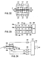
- FIG. 22 is a sectional view taken along the line F-F in FIG. 20.
- FIG. 23 is a top plan view taken along the line G-G in FIG. 21.
- a pressure measurement hole connecting to the pressure sensor 137 is bored in the fixed guide member 108 and the movable guide member 109.
- a groove 143 is provided along the paper sheet P conveying direction. The groove 143 divides the upper surface of the fixed guide member 108 into areas 108a - 108c.
- the hole sensor 139 is provided at four locations in the fixed guide member 108, in FIG. 23, but the same function can be achieved even by providing at one or two locations in the width direction of the fixed guide member 108.
- the position of the width direction of the foreign matter on the surface of the paper sheet P is determined by the output of the pressure sensor 137, and three pressure sensors 137 are provided in the width directions of the fixed and movable guide members 108 and 109, as shown in FIG. 22.
- the groove 143 is formed on the opposite surfaces of the fixed guide member 108 and the movable guide member 109, and an air flow occurs along the groove 143, and an air film is divided in the width direction along the groove 143. Therefore, the air film pressure is separated by the groove 143, and the pressure change in the width direction can be detected.
- the hole sensor 139 As to the output of the hole sensor 139, when a paper sheet P is conveyed and inserted between the fixed and movable guide members 108 and 109, the clearance increases, the distance from the permanent magnet 140 increases, the magnetic field strength decreases, and the signal voltage decreases.
- the maximum thickness of a paper sheet P can be detected by the hole sensor 139, as described above.
- the maximum average thickness in the opposite surfaces of the fixed and movable guide members 108 and 109 can be obtained by detecting the thickness at two or more locations and calculating the mean value.
- FIG. 24 is a schematic configuration diagram showing a signal processing device.
- the pressure sensors 137, 137 are connected to a processing circuit 147 through an amplifier 146.
- a hole sensor 139 is connected to the processing circuit 147 through an amplifier 147.
- a paper sheet detection device 149 provided in the paper sheet take-in side of the guide members 108, 109 is connected to the processing circuit 147 through an amplifier 150.
- the output signal of the paper sheet detector 149, and the signals from the hole sensor 139 and the pressure sensor 137 are applied to the processing circuit 147 through the respective amplifiers 150, 146 and 147, where the signals are processed, and the paper sheet P thickness signal 152 and the surface foreign matter signal 153 are obtained.
- a composite detection apparatus which can detect the thickness and a foreign matter adhered to a paper sheet P during running without contacting the paper sheet P, provide a plurality of foreign matter detection devices in the width direction of the paper sheet, and detect the thickness and the foreign matter on the paper sheet surface, without flapping the paper in the thickness direction.
- FIG. 25 is a top plan view showing a paper sheet detection apparatus according to a seventh embodiment of the present invention.
- FIG. 26 is a front sectional view of the paper sheet detection apparatus.
- FIG. 27 is a front sectional view of the paper sheet detection apparatus in the state that a paper sheet is passing.
- a paper sheet detection apparatus 201 has a pair of conveying belts 202 that holds both sides of a paper sheet P and conveys the paper sheet along a conveying path H.
- the pair of conveying belts 202 is formed with upper and lower conveying belts 202a, 202b.
- a sensor 203 such as a magnetic head is provided as an inspection means.
- the sensor 203 detects the magnetic information of a paper sheet P.
- a paper sheet P is guided by a guide device 204 so that the magnetic information is read well at the sensor 203.
- the guide device 204 has sensor guides 206 and 207 as upper and lower guiding bodies, which are separated and located opposite to each other through the conveying path H.
- the sensor 203 is provided on the upper surface of the lower sensor guide 207.
- the upper sensor guide 206 is supported by a support frame 209 movable vertically through a support rod 210.
- a spring 211 is wound around the support rod 210. The spring 211 elastically energizes the upper sensor guide 206 downward.
- an air chamber 213 is provided, whose lower side is openable.
- a porous ejection device 214 is provided in the opening of the lower side of the air chamber 213.
- the porous ejection device 214 has the advantage of obtaining a relatively uniform static pressure in a wide range by a small compressed air pressure.
- the upper sensor guide 206 is connected with an air tube 215, which connects with the air chamber 213. Compressed fluid, for example, compressed air is supplied from the air tube 217 to the air chamber 213, and the compressed air is ejected from the porous ejection device 214 toward the lower sensor guide 207, as indicated by an arrow.
- the ejected compressed air exists as a static pressure air in the clearance between the opposite lower sensor guide 207, and keeps the distance d between the upper and lower sensor guides 206, 207 by being balanced with the pressing force of the spring 211.
- the pressing force is obtained not only by an elastic body such as a spring 211.
- the same function can be obtained by adjusting the weights of the members constituting the upper sensor guide 206.
- the distance d between the upper and lower sensor guides 206 and 207 is at least about 1.5 time larger than the thickness of a paper sheet P.
- the paper sheet take-in sides of the upper and lower sensor guides 206 and 207 are formed bending and the curved surface is widely opened, so that a paper sheet P butts against and jams at the ends of the upper and lower sensor guides 206 and 207 when it is taken in.
- the paper sheet P conveying force of the pair of conveying belts 2 is set larger than the friction force between the surface of the lower sensor guide 207 and the paper sheet P, to stably convey the paper sheet P.
- the surface of the lower sensor guide 207 is coated with DLC (Diamond Like Carbon), TiN or TiC to decrease the coefficient of friction to 0.2 or lower to make the conveyance of the paper sheet P smoother.
- the static pressure to press a paper sheet P between the upper and lower sensor guides 106 and 107 to the lower sensor guide 107 is equal to the force of raising the upper sensor guide against the pressing force of the spring 211 and forming the distance d to the lower sensor guide 207.
- the force to press a paper sheet P to the lower sensor guide 207 becomes a frictional resistance force against the conveying force, and the frictional force can be obtained by the force obtained by multiplying the coefficient of friction of the lower sensor guide 207 by a load.
- the conveying resistance force can be made sufficiently smaller than the belt conveying force, and stable conveyance can be ensured.
- the upper sensor guide 206 does not come in contact with a paper sheet P, the conveying resistance is small, a paper jam can be avoided and special maintenance is unnecessary.
- adhesion of paper dust and ink coming off from a paper sheet or dust caused by the wearing of a belt to the upper sensor guide 206 can be decreased, and deterioration of the inspection performance can be prevented.
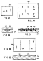
- FIG. 28 is a top plan view showing a first modification of the compressed air ejection device provided in the upper sensor guide 206.
- FIG. 29 is a front sectional view of the device.
- the ejection device is formed with an ejection port 221 in the upper sensor guide 206. According to this modification, there are advantages that an air pressure drop is small, and the costs of cleaning and parts are cheap.
- FIG. 30 is a top plan view showing a second modification of the ejection device.
- FIG. 31 is a front sectional view of the device.
- the ejection device is formed with a plurality of ejection ports 223 in the upper sensor guide 206. According to this modification, there are advantages that an air pressure drop is small, the costs of cleaning and parts are cheap, and a friction resistance during conveying a paper sheet is decreased by not applying static pressure evenly to the whole surface of a paper sheet P.
- FIG. 32 is a top plan view showing a third modification of the ejection device.
- FIG. 33 is a front sectional view of the device.
- the ejection device is formed in the upper sensor guide 206 with a groove 225 with small width along the direction orthogonal to the paper sheet conveying direction. According to this modification, the static pressure air can be distributed more widely and the flapping of a paper sheet P can be effectively suppressed even if the paper is not hardy and flaps largely.
- FIG. 34 is a front sectional view showing a paper sheet detection apparatus according to an eight embodiment of the present invention.
- a transparent plate 231 such as a hard glass is provided in the lower sensor guide 207.
- the wrinkles and bents of the paper sheet P can be smoothed out, and a high-precision optical visual field can be obtained by eliminating the cause of a height fluctuation noise.
- FIG. 35 is a top plan view showing a paper sheet detection apparatus according to a ninth embodiment of the present invention.
- FIG. 36 is a front sectional view of the apparatus.
- a pair of conveying rollers 235 comprising upper and lower rollers 235a and 235b, is disposed outside of the static pressure air area 234, so that a paper sheet P is held and conveyed by the pair of rollers 235.
- FIG. 37 shows a tenth embodiment of the present invention.
- a minute air vent 236 is provided in the lower sensor guide 207.
- the compressed gas ejected from the ejection device 214 in the upper sensor guide 206 presses a paper sheet P to the lower sensor guide 207, and then escapes to the outside through the air vent 236 in the lower sensor guide 207. Therefore, the remaining paper sheet P is prevented from being swollen by the compressed air flowing into the clearance between the paper sheet P and the lower sensor guide 207, and the paper sheet P inspection accuracy can be improved.
- FIG. 38 shows a first modification of the air vent.
- This air vent is composed of a groove 238 with small width formed in the lower sensor guide 207 along the paper sheet P conveying direction.
- FIG. 39 shows a second modification of the air vent.
- This air vent is composed of an uneven part 240 formed on the upper surface of the lower sensor guide 207.
- the air vent can also be a porous block or a small diameter hole, and can be selected depending on the quality of a paper sheet P and the type of the sensor.
- FIG. 40 shows an eleventh embodiment of the present invention.
- a suction pump 246 is connected as a suction means to the lower sensor guide 207 through a suction pipe 245.
- the compressed air ejected from the upper sensor guide 206 is sucked from the lower sensor guide 207 through the suction pipe 245.
- the paper sheet P passing between the upper and lower sensor guides 206 and 207 can be tightly adhered to the lower sensor guide 207 to fit it along its shape, increasing the inspection accuracy of the sensor.
- FIG. 41 shows a twelfth embodiment of the present invention.
- the upper sensor guide 206 is provided with a sensor 251 of the upper side and an ejection device 252, and the lower sensor guide 207 is provided with a sensor 254 of the lower side and an ejection device 253.
- the sensor 251 of the upper side is opposite to the ejection device 253 of the lower side, and the sensor 254 of the lower side is opposite to the ejection device 252 of the upper side.
- Compressed air is blown out from the ejection devices 252, 253 of the upper and lower sensor guides 206, 207, and static air is formed between the upper and lower sensor guides 206, 207.
- the upper side of the paper sheet P is first pressed to the upper sensor 251 and the magnetic information is read, and then the lower side is pressed to the lower sensor 254 and the magnetic information is read.
- the front and back of a paper sheet P can be inspected by passing only once between the upper and lower sensor guides 206, 207, increasing the processing efficiency.
Landscapes
- Engineering & Computer Science (AREA)
- Mechanical Engineering (AREA)
- Controlling Sheets Or Webs (AREA)
- Delivering By Means Of Belts And Rollers (AREA)
- Feeding Of Articles By Means Other Than Belts Or Rollers (AREA)
Abstract
Description
Claims (16)
- A paper sheet detection apparatus characterized by comprising:a conveying device (1, 2, 31, 35) which conveys a paper sheet along a conveying surface (H);a detection device (12, 33) which is provided opposite to the conveying surface (H) and detects a paper sheet conveyed by the conveying device (1, 2, 31, 35);a guide device (3, 32, 34, 71, 85) which is provided in at least the paper sheet take-in side of the detection device (12, 33) and formed with a pair of guide members (5, 6, 50, 51, 53, 54, 72, 73, 86, 87) disposed opposite to each other at both sides of the conveying surface (H);a nozzle (27a, 27b) which is provided in the opposite surface of the pair of guide members (5, 6, 50, 51, 53, 54, 72, 73, 86, 87); anda gas supply device (64, 90) which supplies compressed gas to the pair of guide members (5, 6, 50, 51, 53, 54, 72, 73, 86, 87) and ejects the gas from the nozzle (27a, 27b) between the pair of guide members (5, 6, 50, 51, 53, 54, 72, 73, 86, 87).
- The paper sheet detection apparatus according to claim 1, characterized by comprising:wherein the gas supply device (64, 90) generates a clearance between the pair of guide members (5, 6, 50, 51, 53, 54, 72, 73, 86, 87) by moving one of the pair of guide members against the energizing force for the energizing device (20, 49, 82), by supplying compressed gas to the pair of guide members (5, 6, 50, 51, 53, 54, 72, 73, 86, 87) and ejecting the gas from the nozzle between the pair of guide members (5, 6, 50, 51, 53, 54, 72, 73, 86, 87).an energizing device (20, 49, 82) which elastically energizes one of the pair of guide members (5, 6, 50, 51, 53, 54, 72, 73, 86, 87) toward the other guide member (6, 51, 54, 73, 87),
- The paper sheet detection apparatus according to claim 1 or 2, characterized by further comprising a plurality of grooves (ab - mn) provided at a certain interval on the opposite surface of said pair of guide members (50, 51, 53, 54) in the paper sheet conveying direction and in the direction orthogonal to the the conveying direction, and a plurality of nozzles (aj - en) provided at least in the parts surrounded by said plurality of grooves (ab - mn) on the opposite surface of said pair of guide members (50, 51, 53, 54).
- The paper sheet detection apparatus according to claim 3, characterized in that said plurality of nozzles (aj - en) are disposed like a column on the line parallel to the paper sheet conveying direction, and the interval between the outermost nozzle column is set wider than the width dimension of the paper sheet in the direction orthogonal to the conveying direction.
- The paper sheet detection apparatus according to one of claims 1 to 4, characterized in that one of said pair of guide members (72, 73) consists of a plurality of divided guides (72a) divided vertically and horizontally along the paper sheet conveying direction and the direction orthogonal to the conveying direction; and each of the divided guides (72a) is provided movable, and has a nozzle to eject compressed gas.
- The paper sheet detection apparatus according to one of claims 1 to 4, characterized in that one of said pair of guide members (86, 87) consists of a plurality of divided guides (86a - 86e) divided over the paper sheet conveying direction; each of the divided guide parts (86a - 86e) has a nozzle to eject compressed gas; the gas supply device (90) controls the supply of compress gas to said plurality of divided guide members (86a - 86e) by switching the pressure and flow rate to be different at a certain cycle, and moves a pressure fluctuation or a flow rate fluctuation of the compressed gas ejected from the nozzles of said plurality of divided guides (86a - 86e) along the paper sheet conveying direction.
- The paper sheet detection apparatus according to claim 6, characterized in that the gas supply device (90) generates a pressure fluctuation or a flow rate fluctuation of the compressed air blown out from the nozzle, according to the height or the flow rate increment and decrement of the pressure of the compressed gas supplied to the divided guides (86a - 86e).
- The paper sheet detection apparatus according to one of claims 1 to 7, characterized in that the other one of said pair of guide members (5, 6, 50, 51, 53, 54, 72, 73, 86, 87) is fixedly provided.
- The paper sheet detection apparatus according to one of claims 1 to 8, characterized in that the guide device (32, 34) is provided in the paper sheet take-in side and take-out side of the detection device (33).
- A paper sheet detection apparatus characterized by comprising:a conveying device (101, 102) which conveys a paper sheet along a conveying path (110);a guide device (108, 109) which has a pair of guide members (108, 109) separated and opposed through the conveying path (110), and passes and guides the paper sheet between said pair of guide members (108, 109);an inspection device (108, 109) which is formed with a wave transmitter (103) provided in on one of said pair of guide members (108, 109) and radiates a sound wave to the conveyed paper sheet, and a wave receiver (104) provided in the other of said pair of guide members (108, 109), and receives the sound wave passing through the paper sheet;a nozzle (121, 122) which is provided in the opposite surfaces of said pair of guide members (108, 109); anda gas supply device which supplies compressed gas to said pair of guide members (108, 109), and ejects the gas from the nozzles (121, 122) to between said pair of guide members (108, 109).
- A paper sheet detection apparatus characterized by comprising:a conveying device (101, 102) which conveys a paper sheet along a conveying path (110);a guide device (108, 109) which has a pair of guide members (108, 109) separated and opposed through the conveying path (110), and passes and guides the paper sheet between said pair of guide members (108, 109);an inspection device (137) which is formed with a pressure sensor (137) provided in each of said pair of guide members (108, 109);a nozzle (121, 122) which is provided in the opposite surfaces of said pair of guide members (108, 109); anda gas supply device which supplies compressed gas to said pair of guide members (108, 109), and ejects the gas from the nozzles (121, 122) to between said pair of guide members (108, 109).
- A paper sheet detection apparatus characterized by comprising:a conveying device (202, 235) which conveys a paper sheet along a conveying path (H);a guide device (204) which has a pair of guide members (206, 207) separated and opposed through the conveying path (H), and passes and guides the paper sheet between said pair of guide members (206, 207);an inspection device (203) which is provided in one of said pair of guide bodies (206, 207), and inspects the conveyed paper sheet; anda gas ejection device (214) which is provided in the other of said pair of guide members (206, 207), ejects compressed air to form a static pressure gas layer between said pair of guide members (206, 207), and presses the conveyed paper sheet to one of said pair of guide members (206, 207) by the static gas layer.
- The paper sheet detection apparatus according to claim 12, characterized by further comprising an energizing device (211) which elastically energizes the other guide member (206) toward one guide member (207).
- The paper sheet detection apparatus according to claim 12 or 13, characterized in that the gas ejection device (214) is porous, or has a nozzle hole or a groove-like ejection device.
- The paper sheet detection apparatus according to one of claims 12 to 14, characterized in that said one guide member (207) consists of a transparent plate (231).
- The paper sheet detection apparatus according to one of claims 12 to 15, characterized in that the conveying device (235) has a pair of conveying rollers (235) disposed in the paper sheet take-in side and take-out side of the guide device (204), and a paper sheet is held and conveyed by said pair of conveying rollers (235).
Applications Claiming Priority (2)
| Application Number | Priority Date | Filing Date | Title |
|---|---|---|---|
| JP2002304619 | 2002-10-18 | ||
| JP2002304619A JP2004137054A (en) | 2002-10-18 | 2002-10-18 | Paper sheet detector |
Publications (3)
| Publication Number | Publication Date |
|---|---|
| EP1411010A2 true EP1411010A2 (en) | 2004-04-21 |
| EP1411010A3 EP1411010A3 (en) | 2004-06-09 |
| EP1411010B1 EP1411010B1 (en) | 2006-05-10 |
Family
ID=32040866
Family Applications (1)
| Application Number | Title | Priority Date | Filing Date |
|---|---|---|---|
| EP03020948A Expired - Lifetime EP1411010B1 (en) | 2002-10-18 | 2003-09-16 | Paper sheet detection apparatus |
Country Status (5)
| Country | Link |
|---|---|
| US (1) | US7011307B2 (en) |
| EP (1) | EP1411010B1 (en) |
| JP (1) | JP2004137054A (en) |
| AT (1) | ATE325763T1 (en) |
| DE (1) | DE60305122T2 (en) |
Cited By (3)
| Publication number | Priority date | Publication date | Assignee | Title |
|---|---|---|---|---|
| WO2008135243A3 (en) * | 2007-05-04 | 2009-05-28 | Giesecke & Devrient Gmbh | Device and method for positioning and/or guiding a valuable document |
| WO2010066793A1 (en) * | 2008-12-10 | 2010-06-17 | Giesecke & Devrient Gmbh | Method and device for guiding value documents |
| CN102019276A (en) * | 2009-09-16 | 2011-04-20 | 株式会社东芝 | Document sorting apparatus and document sorting method |
Families Citing this family (15)
| Publication number | Priority date | Publication date | Assignee | Title |
|---|---|---|---|---|
| EP1779310B1 (en) * | 2004-07-01 | 2012-09-19 | Diebold, Incorporated | Automated banking machine multiple sheet detector apparatus and method |
| JP4812114B2 (en) * | 2007-02-23 | 2011-11-09 | オムロン株式会社 | Paper sheet multi-feed detection device and paper multi-feed detection method |
| US8752831B2 (en) * | 2008-10-06 | 2014-06-17 | Xerox Corporation | Systems and methods for controlling substrate flatness in printing devices using the flow of air |
| US8186675B2 (en) * | 2008-10-06 | 2012-05-29 | Xerox Corporation | Systems and methods for controlling substrate flatness in printing devices using vacuum and/or the flow of air |
| US7957657B2 (en) * | 2009-02-12 | 2011-06-07 | Xerox Corporation | Universal module for enabling measurements on color printers |
| DE102010026341A1 (en) * | 2010-07-07 | 2012-01-12 | Giesecke & Devrient Gmbh | Ultrasonic sensor for value documents, converter module for this and method for producing the ultrasonic sensor |
| JP6135139B2 (en) * | 2013-01-17 | 2017-05-31 | セイコーエプソン株式会社 | Liquid ejection device |
| CN103240915B (en) * | 2013-05-15 | 2015-04-08 | 常州市恒成塑料机械有限公司 | Crosscutting and conveying device for woven plastic cylindrical cloth for block bottom valve bag production |
| US9505571B2 (en) * | 2013-12-10 | 2016-11-29 | Toshiba International Corporation | Bank note processing system having a high speed note processing path |
| KR101607380B1 (en) | 2014-04-23 | 2016-03-29 | 주식회사 엘지씨엔에스 | Media recognizing apparatus and financial device |
| US11298963B2 (en) * | 2017-11-29 | 2022-04-12 | Landa Corporation Ltd. | Protection of components of digital printing systems |
| EP3837199B1 (en) * | 2018-08-14 | 2022-04-06 | Bobst Mex Sa | Inkjet printing machine for printing individual sheets |
| US11148454B2 (en) * | 2018-08-31 | 2021-10-19 | Canon Finetech Nisca Inc. | Sheet bundle discharging apparatus and bookbinding apparatus |
| CN113646248B (en) | 2019-04-03 | 2024-06-11 | 兰达公司 | Digital printing system having a paper conveyor provided with a rotatable element to eliminate damage to the paper |
| CN216376702U (en) * | 2021-03-30 | 2022-04-26 | 东莞富崴电子有限公司 | Air flow conveying device |
Family Cites Families (15)
| Publication number | Priority date | Publication date | Assignee | Title |
|---|---|---|---|---|
| BE571375A (en) * | 1958-04-11 | |||
| US2992822A (en) * | 1958-10-24 | 1961-07-18 | Burroughs Corp | Multiple item detector for document handling machines |
| US3133481A (en) * | 1961-06-29 | 1964-05-19 | Owens Illinois Glass Co | Article feed control apparatus and method |
| NL295100A (en) * | 1962-07-09 | |||
| US3136539A (en) * | 1962-12-03 | 1964-06-09 | Lyman Brooks | Sheet handling |
| US3360262A (en) * | 1966-06-16 | 1967-12-26 | Gregory C Kekopoulos | Apparatus for moving and aligning limp pieces of material |
| GB1326504A (en) * | 1971-04-28 | 1973-08-15 | Int Computers Ltd | Devices for detecting documents |
| JPS59150303A (en) * | 1983-02-10 | 1984-08-28 | Toshiba Corp | Thickness detection apparatus of paper sheet material |
| US4608856A (en) * | 1983-05-11 | 1986-09-02 | John L. Williams | Double feed detection device |
| CA1263125A (en) * | 1984-06-01 | 1989-11-21 | Hans-Guenter E. Kuehnert | Apparatus for the automatic feeding of a laminating station |
| US5344521A (en) * | 1991-04-10 | 1994-09-06 | Canon Kabushiki Kaisha | Coating film separating device and coating film separation method using the device |
| US5634636A (en) * | 1996-01-11 | 1997-06-03 | Xerox Corporation | Flexible object handling system using feedback controlled air jets |
| DE10057570B4 (en) * | 1999-12-15 | 2005-11-24 | Heidelberger Druckmaschinen Ag | Guide device of a sheet-like substrates processing machine |
| JP3923726B2 (en) | 1999-12-15 | 2007-06-06 | 株式会社東芝 | Characteristic detection device that detects the characteristics of paper sheets |
| US6442369B1 (en) * | 2000-11-27 | 2002-08-27 | Xerox Corporation | Air bearing mechanism for flattening paper in a printing machine |
-
2002
- 2002-10-18 JP JP2002304619A patent/JP2004137054A/en not_active Abandoned
-
2003
- 2003-09-16 DE DE60305122T patent/DE60305122T2/en not_active Expired - Fee Related
- 2003-09-16 EP EP03020948A patent/EP1411010B1/en not_active Expired - Lifetime
- 2003-09-16 AT AT03020948T patent/ATE325763T1/en not_active IP Right Cessation
- 2003-09-22 US US10/665,575 patent/US7011307B2/en not_active Expired - Fee Related
Cited By (6)
| Publication number | Priority date | Publication date | Assignee | Title |
|---|---|---|---|---|
| WO2008135243A3 (en) * | 2007-05-04 | 2009-05-28 | Giesecke & Devrient Gmbh | Device and method for positioning and/or guiding a valuable document |
| WO2010066793A1 (en) * | 2008-12-10 | 2010-06-17 | Giesecke & Devrient Gmbh | Method and device for guiding value documents |
| US8317194B2 (en) | 2008-12-10 | 2012-11-27 | Giesecke & Devrient Gmbh | Method and device for guiding value documents |
| AU2009324402B2 (en) * | 2008-12-10 | 2014-05-22 | Giesecke & Devrient Gmbh | Method and device for guiding value documents |
| CN102317184B (en) * | 2008-12-10 | 2015-04-01 | 德国捷德有限公司 | Method and device for guiding value documents |
| CN102019276A (en) * | 2009-09-16 | 2011-04-20 | 株式会社东芝 | Document sorting apparatus and document sorting method |
Also Published As
| Publication number | Publication date |
|---|---|
| EP1411010B1 (en) | 2006-05-10 |
| DE60305122T2 (en) | 2006-10-26 |
| US20040075213A1 (en) | 2004-04-22 |
| US7011307B2 (en) | 2006-03-14 |
| EP1411010A3 (en) | 2004-06-09 |
| DE60305122D1 (en) | 2006-06-14 |
| JP2004137054A (en) | 2004-05-13 |
| ATE325763T1 (en) | 2006-06-15 |
Similar Documents
| Publication | Publication Date | Title |
|---|---|---|
| US20040075213A1 (en) | Paper sheet detection apparatus | |
| EP1436569B1 (en) | Non-contact sheet sensing system and related method | |
| US6141883A (en) | Apparatus for detecting the thickness of documents | |
| FI125343B (en) | Track thickness measuring device | |
| JP4960466B2 (en) | Paper sheet processing equipment | |
| EP0657712B1 (en) | Thickness detecting device in a mail processing system | |
| US20090096156A1 (en) | Device for Conveying Sheets that Comprises a Sheet Directing Element | |
| CN114269564A (en) | Non-contact liquid application apparatus and method | |
| WO2000005565A1 (en) | Ventilation characteristic measuring device | |
| FI99162C (en) | Thickness gauge for moving sheet material | |
| US9234851B2 (en) | Color measurement system including lateral moving measurment carriage | |
| US20110108469A1 (en) | Limpness detecting device, limpness detecting method, and sheet handling apparatus including limpness detecting device | |
| US7151608B2 (en) | Method for measuring the thickness of a mail item | |
| US6247861B1 (en) | Controlling vacuum hold of media in a printer | |
| US5670880A (en) | Apparatus for testing magnetic properties of sheet material such as bank notes or papers of value | |
| US7156238B2 (en) | Apparatus for inspecting sealed packages | |
| US7478807B2 (en) | Method for conveying a sheet and apparatus for carrying out the method | |
| JP4575533B2 (en) | Non-contact fluid measuring device | |
| EP1286228A3 (en) | Pre-fuser transport assembly | |
| JP2005172745A (en) | Paper sheet thickness detection device and foreign matter detection device | |
| CN102317184A (en) | Method and device for guiding value documents | |
| EP1443454B1 (en) | Magnetic detection device | |
| JP2005067750A (en) | Paper sheet inspection device | |
| JPH04215001A (en) | Sheet thickness detecting mechanism | |
| JP2001233501A (en) | A characteristic detection device that detects the characteristics of paper sheets |
Legal Events
| Date | Code | Title | Description |
|---|---|---|---|
| PUAI | Public reference made under article 153(3) epc to a published international application that has entered the european phase |
Free format text: ORIGINAL CODE: 0009012 |
|
| 17P | Request for examination filed |
Effective date: 20030916 |
|
| AK | Designated contracting states |
Kind code of ref document: A2 Designated state(s): AT BE BG CH CY CZ DE DK EE ES FI FR GB GR HU IE IT LI LU MC NL PT RO SE SI SK TR |
|
| AX | Request for extension of the european patent |
Extension state: AL LT LV MK |
|
| PUAL | Search report despatched |
Free format text: ORIGINAL CODE: 0009013 |
|
| AK | Designated contracting states |
Kind code of ref document: A3 Designated state(s): AT BE BG CH CY CZ DE DK EE ES FI FR GB GR HU IE IT LI LU MC NL PT RO SE SI SK TR |
|
| AX | Request for extension of the european patent |
Extension state: AL LT LV MK |
|
| AKX | Designation fees paid |
Designated state(s): AT DE FR IT |
|
| GRAP | Despatch of communication of intention to grant a patent |
Free format text: ORIGINAL CODE: EPIDOSNIGR1 |
|
| GRAS | Grant fee paid |
Free format text: ORIGINAL CODE: EPIDOSNIGR3 |
|
| GRAA | (expected) grant |
Free format text: ORIGINAL CODE: 0009210 |
|
| AK | Designated contracting states |
Kind code of ref document: B1 Designated state(s): AT DE FR IT |
|
| REF | Corresponds to: |
Ref document number: 60305122 Country of ref document: DE Date of ref document: 20060614 Kind code of ref document: P |
|
| PGFP | Annual fee paid to national office [announced via postgrant information from national office to epo] |
Ref country code: FR Payment date: 20060908 Year of fee payment: 4 |
|
| PGFP | Annual fee paid to national office [announced via postgrant information from national office to epo] |
Ref country code: AT Payment date: 20060913 Year of fee payment: 4 |
|
| PGFP | Annual fee paid to national office [announced via postgrant information from national office to epo] |
Ref country code: DE Payment date: 20060914 Year of fee payment: 4 |
|
| PGFP | Annual fee paid to national office [announced via postgrant information from national office to epo] |
Ref country code: IT Payment date: 20060930 Year of fee payment: 4 |
|
| ET | Fr: translation filed | ||
| PLBE | No opposition filed within time limit |
Free format text: ORIGINAL CODE: 0009261 |
|
| STAA | Information on the status of an ep patent application or granted ep patent |
Free format text: STATUS: NO OPPOSITION FILED WITHIN TIME LIMIT |
|
| 26N | No opposition filed |
Effective date: 20070213 |
|
| PG25 | Lapsed in a contracting state [announced via postgrant information from national office to epo] |
Ref country code: AT Free format text: LAPSE BECAUSE OF NON-PAYMENT OF DUE FEES Effective date: 20070916 |
|
| PG25 | Lapsed in a contracting state [announced via postgrant information from national office to epo] |
Ref country code: DE Free format text: LAPSE BECAUSE OF NON-PAYMENT OF DUE FEES Effective date: 20080401 |
|
| REG | Reference to a national code |
Ref country code: FR Ref legal event code: ST Effective date: 20080531 |
|
| PG25 | Lapsed in a contracting state [announced via postgrant information from national office to epo] |
Ref country code: FR Free format text: LAPSE BECAUSE OF NON-PAYMENT OF DUE FEES Effective date: 20071001 |
|
| PG25 | Lapsed in a contracting state [announced via postgrant information from national office to epo] |
Ref country code: IT Free format text: LAPSE BECAUSE OF NON-PAYMENT OF DUE FEES Effective date: 20070916 |