EP1410814A2 - Liquid medicine infusion apparatus - Google Patents
Liquid medicine infusion apparatus Download PDFInfo
- Publication number
- EP1410814A2 EP1410814A2 EP03023577A EP03023577A EP1410814A2 EP 1410814 A2 EP1410814 A2 EP 1410814A2 EP 03023577 A EP03023577 A EP 03023577A EP 03023577 A EP03023577 A EP 03023577A EP 1410814 A2 EP1410814 A2 EP 1410814A2
- Authority
- EP
- European Patent Office
- Prior art keywords
- liquid medicine
- pressurizing
- infusion apparatus
- opening
- closing
- Prior art date
- Legal status (The legal status is an assumption and is not a legal conclusion. Google has not performed a legal analysis and makes no representation as to the accuracy of the status listed.)
- Withdrawn
Links
- 0 *CC1CCCC1 Chemical compound *CC1CCCC1 0.000 description 1
Images



Classifications
-
- A—HUMAN NECESSITIES
- A61—MEDICAL OR VETERINARY SCIENCE; HYGIENE
- A61M—DEVICES FOR INTRODUCING MEDIA INTO, OR ONTO, THE BODY; DEVICES FOR TRANSDUCING BODY MEDIA OR FOR TAKING MEDIA FROM THE BODY; DEVICES FOR PRODUCING OR ENDING SLEEP OR STUPOR
- A61M5/00—Devices for bringing media into the body in a subcutaneous, intra-vascular or intramuscular way; Accessories therefor, e.g. filling or cleaning devices, arm rests
- A61M5/14—Infusion devices, e.g. infusing by gravity; Blood infusion; Accessories therefor
- A61M5/142—Pressure infusion, e.g. using pumps
- A61M5/145—Pressure infusion, e.g. using pumps using pressurised reservoirs, e.g. by means of pistons
- A61M5/148—Pressure infusion, e.g. using pumps using pressurised reservoirs, e.g. by means of pistons flexible
- A61M5/1483—Pressure infusion, e.g. using pumps using pressurised reservoirs, e.g. by means of pistons flexible using flexible bags externally pressurised by fluid pressure
-
- A—HUMAN NECESSITIES
- A61—MEDICAL OR VETERINARY SCIENCE; HYGIENE
- A61M—DEVICES FOR INTRODUCING MEDIA INTO, OR ONTO, THE BODY; DEVICES FOR TRANSDUCING BODY MEDIA OR FOR TAKING MEDIA FROM THE BODY; DEVICES FOR PRODUCING OR ENDING SLEEP OR STUPOR
- A61M5/00—Devices for bringing media into the body in a subcutaneous, intra-vascular or intramuscular way; Accessories therefor, e.g. filling or cleaning devices, arm rests
- A61M5/14—Infusion devices, e.g. infusing by gravity; Blood infusion; Accessories therefor
- A61M5/142—Pressure infusion, e.g. using pumps
- A61M5/145—Pressure infusion, e.g. using pumps using pressurised reservoirs, e.g. by means of pistons
- A61M5/1452—Pressure infusion, e.g. using pumps using pressurised reservoirs, e.g. by means of pistons pressurised by means of pistons
- A61M5/1454—Pressure infusion, e.g. using pumps using pressurised reservoirs, e.g. by means of pistons pressurised by means of pistons spring-actuated, e.g. by a clockwork
-
- A—HUMAN NECESSITIES
- A61—MEDICAL OR VETERINARY SCIENCE; HYGIENE
- A61M—DEVICES FOR INTRODUCING MEDIA INTO, OR ONTO, THE BODY; DEVICES FOR TRANSDUCING BODY MEDIA OR FOR TAKING MEDIA FROM THE BODY; DEVICES FOR PRODUCING OR ENDING SLEEP OR STUPOR
- A61M5/00—Devices for bringing media into the body in a subcutaneous, intra-vascular or intramuscular way; Accessories therefor, e.g. filling or cleaning devices, arm rests
- A61M5/14—Infusion devices, e.g. infusing by gravity; Blood infusion; Accessories therefor
- A61M5/142—Pressure infusion, e.g. using pumps
- A61M5/145—Pressure infusion, e.g. using pumps using pressurised reservoirs, e.g. by means of pistons
- A61M5/148—Pressure infusion, e.g. using pumps using pressurised reservoirs, e.g. by means of pistons flexible
- A61M5/152—Pressure infusion, e.g. using pumps using pressurised reservoirs, e.g. by means of pistons flexible pressurised by contraction of elastic reservoirs
-
- A—HUMAN NECESSITIES
- A61—MEDICAL OR VETERINARY SCIENCE; HYGIENE
- A61M—DEVICES FOR INTRODUCING MEDIA INTO, OR ONTO, THE BODY; DEVICES FOR TRANSDUCING BODY MEDIA OR FOR TAKING MEDIA FROM THE BODY; DEVICES FOR PRODUCING OR ENDING SLEEP OR STUPOR
- A61M5/00—Devices for bringing media into the body in a subcutaneous, intra-vascular or intramuscular way; Accessories therefor, e.g. filling or cleaning devices, arm rests
- A61M5/14—Infusion devices, e.g. infusing by gravity; Blood infusion; Accessories therefor
- A61M5/168—Means for controlling media flow to the body or for metering media to the body, e.g. drip meters, counters
- A61M5/16804—Active flow controllers
- A61M5/16809—Active flow controllers by repeated filling and emptying of an intermediate volume
-
- A—HUMAN NECESSITIES
- A61—MEDICAL OR VETERINARY SCIENCE; HYGIENE
- A61M—DEVICES FOR INTRODUCING MEDIA INTO, OR ONTO, THE BODY; DEVICES FOR TRANSDUCING BODY MEDIA OR FOR TAKING MEDIA FROM THE BODY; DEVICES FOR PRODUCING OR ENDING SLEEP OR STUPOR
- A61M2205/00—General characteristics of the apparatus
- A61M2205/33—Controlling, regulating or measuring
- A61M2205/3331—Pressure; Flow
Definitions
- the present invention relates to an infusion apparatus for administering a liquid medicine into a blood vessel, extradural cavity or hypodermically in small increments.
- the invention relates to a liquid medicine infusion apparatus which can maintain a predetermined infusion rate stably for a long time without regard to the type of liquid medicine or the ambient temperature.
- liquid medicines such as antibiotics and anti-cancer medicines and anesthetics
- some liquid medicines are preferably administered into a blood vessel, extradural cavity or hypodermically little by little over a long time.
- known liquid medicine infusion apparatuses used for this purpose include a syringe pump type, in which the plunger of a syringe is pushed little by little by means such as a motor to thereby infuse the liquid medicine, and a roller pump type, in which a tube which is a conduit for a liquid medicine is slowly squeezed by a roller to force out the liquid medicine. Since these liquid medicine infusion apparatuses use electric power, they have an advantage that they can maintain an accurate infusion rate.
- Japanese Patent Unexamined Publication No. 2-11160 discloses a liquid medicine infusion apparatus in which a flow rate control unit composed of a tube having a small diameter is connected to liquid medicine pressurizing/supplying means such as a balloon.
- a flow rate control unit composed of a tube having a small diameter
- liquid medicine pressurizing/supplying means such as a balloon.
- the infusion rate of a liquid medicine forced out from the balloon is controlled to a predetermined constant value due to the line resistance of the small-diameter inner tube while the liquid medicine passes through the flow rate control unit consisting of the small-diameter tube.
- the viscosity of a liquid medicine becomes lower as the temperature rises according to the general properties of a fluid. Therefore, the flow rate of the liquid medicine increases in inverse proportion to the rise in the temperature of the liquid medicine.
- the viscosity at 25°C of fluorouracil which is an anti-malignant antineoplastic agent is 1.273 g/cm ⁇ s whereas its viscosity at 32°C is reduced to 1.084 g/cm ⁇ s. Therefore, the flow rate at 32°C of fluorouracil is about 17.4% higher than that at 25°C.
- the viscosity of a liquid medicine differs according to the type of the liquid medicine as well.
- the viscosity at 25°C of fluorouracil is 1.273 g/cm ⁇ s whereas the viscosity at 25°C of cisplatin which is an anti-malignant tumor platinum complex is 0.898 g/cm ⁇ s. Therefore, the flow rate of a liquid medicine varies according to the type of the liquid medicine as well.
- a liquid medicine infusion apparatus having a flow rate control unit, which consists of a small-diameter inner tube, connected to liquid medicine pressurizing/supplying means has a drawback in that a predetermined constant infusion rate cannot be obtained when the viscosity of a liquid medicine changes according to the type and temperature of the liquid medicine.
- liquid medicine infusion apparatuses cannot be used for a long time without a large-sized battery or the liquid medicine infusion rate thereof is affected by the type and temperature of a liquid medicine.
- the inventors of the present invention have conducted intensive studies to solve the above problems and have found that the above problems can be solved by controlling the flow rate with a novel mechanism without using a small-diameter tube as a flow rate control unit in a liquid medicine infusion apparatus which includes a liquid medicine pressurizing/supplying means and a flow rate control unit connected to the liquid medicine pressurizing/supplying means.
- the present invention has been accomplished based on this finding.
- the present invention relates to a liquid medicine infusion apparatus characterized by including the following means (a) to (e):
- the pressurizing means of the liquid medicine pressurizing/supplying means is a rubber elastic body, a spring, or air pressure.
- the pressurizing means of the secondary pressurizing means is a rubber elastic body, a spring, or air pressure.
- the upstream opening/closing means and the downstream opening/closing means are comprised of electromagnetic valves, clamps, or an integrated unit using a stopcock.
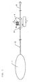
- Fig. 1 is a schematic diagram of a liquid medicine infusion apparatus according to one embodiment of the present invention.
- the liquid medicine infusion apparatus of Fig.1 includes liquid medicine pressurizing/supplying means 1, secondary pressurizing means 5, upstream opening/closing means 3, downstream opening/closing means 4, and control means 7 for controlling the opening/closing timing of the upstream opening/closing means and of the downstream opening/closing means.
- the liquid medicine pressurizing/supplying means 1 and the secondary pressurizing means 5 are connected to each other by an upstream passage 2 and a downstream passage 6 is provided downstream of the secondary pressurizing means 5.
- the liquid medicine pressuring/supplying means 1 stores and forces out the liquid medicine toward the secondary pressuring means 5 by pressurization to cause a flow of the liquid medicine.
- the liquid medicine pressuring/supplying means 1 there may be used a balloon which makes use of the shrinkage force of a rubber elastic body.
- the liquid medicine is stored inside of the expanded balloon.
- the balloon is shrunk by natural force of the rubber elastic body.
- a syringe which makes use of the resilient pressure of a spring is also used as the liquid medicine pressuring/supplying means 1.
- the liquid medicine is stored inside of the syringe and forced out of the syringe using a plunger having a resilient spring.
- a pressure bag which makes use of air pressure is also used.
- the pressure bag is made of a flexible plastic film and contained in the hard container.
- the liquid medicine is stored in the bag and forced out of the bag using an air introduction into the hard container to press the bag.
- a means that mechanically pressurizes a bag filled with the liquid medicine by a pump, such as infusion pump is also used.
- a pressure of 50 to 100 kPa is desirably applied to the liquid medicine to force it out toward the secondary pressuring means 5.
- the secondary pressurizing means 5 is connected in liquid communication with the liquid medicine pressurizing/supplying means 1 by the upstream passage 2, temporarily stores the liquid medicine supplied from the liquid medicine pressurizing/supplying means 1, and forces it out toward the downstream side by pressurization.
- the secondary pressurizing means 5 shown in Fig. 1 consists of a spring 51, a gasket 52, and a cylinder 53, and generates internal pressure by making use of the elastic force of the spring.
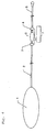
- Other examples of the secondary pressurizing means include those which generate internal pressure by using a plastic sheet 54 such as a vinyl chloride, silicone rubber, or thermoplastic elastomer sheet in place of the gasket and pressing it by the spring 51 as shown in Fig.
- the pressure (internal pressure) of the secondary pressurizing means 5 is generally set to a value 10 to 20% lower than the pressure of the liquid medicine pressurizing/supplying means 1. Therefore, the liquid medicine can flow from the liquid medicine pressurizing/supplying means 1 to the secondary pressurizing means 5.
- the upstream opening/closing means 3 is arranged in the upstream passage 2 to open or close the liquid communication between the liquid medicine pressurizing/supplying means 1 and the secondary pressurizing means 5.
- the downstream opening/closing means 4 is arranged in the downstream passage 6 provided downstream of the secondary pressurizing means 5 to open or close the liquid communication between the secondary pressurizing means 5 and the downstream passage 6. It is preferred that the upstream opening/closing means 3 and the downstream opening/closing means 4 can be opened/closed with an operational force as small as possible to allow usage for a long time.
- the upstream opening/closing means 3 and the downstream opening/closing means 4 are not necessarily separate units and can be integrated into a single unit capable of performing the functions of both means.
- the upstream opening/closing means 3 and the downstream opening/closing means 4 shown in Fig. 1 are electromagnetic valves.
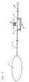
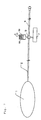
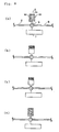
- Other examples of the upstream opening/closing means 3 and the downstream opening/closing means 4 include clamps for clamping a tube used as the liquid medicine passage from outside to close the passage at predetermined time intervals by making use of the rotation of a motor 8 shown in Figs. 5 and 6, and an integrated unit obtained by integrating the upstream opening/closing means 3 and the downstream opening/closing means 4 by making use of a stopcock 9 shown in Figs. 7 and 8.
- the present invention is not limited to these means.
- the suitable materials of the first and second passages 2 and 6 are thermoplastic tubing made of polyvinyl chloride, polyethylene, polybutadiene, silicone and the like.
- the suitable inner diameter of the tubing is from about 0.5 mm to about 5mm.
- the first and second passage 2 and 6 do not restrict the flow of the liquid medicine.
- control means 7 serves to control the opening/closing timing of the upstream opening/closing means 3 and of the downstream opening/closing means 4.
- the control of the opening/closing timing of these opening/closing means makes it possible to attain a predetermined liquid medicine infusion rate in the liquid medicine infusion apparatus of the present invention.
- the liquid medicine infusion apparatus of the present invention infuses a liquid medicine by controlling the opening/closing timing of the upstream opening/closing means 3 and of the downstream opening/closing means 4 by the control means 7.
- the above operation of dosing a patient with the liquid medicine little by little intermittently is repeated so that the liquid medicine infusion apparatus of the present invention can infuse the liquid medicine stably while maintaining a fixed infusion rate.
- the inner capacity of the secondary pressurizing means 5 is 0.05 ml and the liquid medicine infusion operation is repeated once a minute, 0.05 ml per minute or 3 ml per hour of a liquid medicine is dosed to a patient.
- the liquid medicine infusion rate (dose of the liquid medicine to a patient per unit time) can be controlled by adjusting the opening/closing timing of the upstream opening/closing means and of the downstream opening/closing means by the control means.
- the liquid medicine infusion apparatus of the present invention has an advantage in that a predetermined fixed infusion rate can be maintained even when the viscosity of a liquid medicine changes due to a change in the type or temperature of the liquid medicine because it controls the liquid medicine infusion rate (flow rate) without making use of the line resistance of a small-diameter tube, unlike conventional liquid medicine infusion apparatuss in which liquid medicine pressurizing/supplying means such as a balloon is connected to a flow control unit composed of a small-diameter tube.
- the liquid medicine infusion apparatus of the present invention requires no electric energy, or even if it does, it requires only the electric energy necessary for the control means to open or close the upstream opening/closing means and the downstream opening/closing means. Therefore, the liquid medicine infusion apparatus of the present invention does not require a large battery even when it is used for a long time, thereby making it possible to reduce the weight of a pump itself. Accordingly, the liquid medicine infusion apparatus of the present invention has advantages in that it can be conveniently carried by a patient and its cost can be reduced.
Landscapes
- Health & Medical Sciences (AREA)
- Vascular Medicine (AREA)
- Engineering & Computer Science (AREA)
- Anesthesiology (AREA)
- Biomedical Technology (AREA)
- Heart & Thoracic Surgery (AREA)
- Hematology (AREA)
- Life Sciences & Earth Sciences (AREA)
- Animal Behavior & Ethology (AREA)
- General Health & Medical Sciences (AREA)
- Public Health (AREA)
- Veterinary Medicine (AREA)
- Physics & Mathematics (AREA)
- Fluid Mechanics (AREA)
- Infusion, Injection, And Reservoir Apparatuses (AREA)
Abstract

Description
Claims (10)
- A liquid medicine infusion apparatus for infusing a liquid medicine by comprising:(a) a liquid medicine pressurizing/supplying means (1) for exerting pressure on the liquid medicine and causing the liquid medicine to flow through a first passage (2);(b) a secondary liquid medicine pressurizing means (5) which is connected in liquid communication with the liquid medicine pressurizing/supplying means (1) by said first passage (2) and which is sized to receive an increment of liquid medicine from the liquid medicine pressuring/supplying means (1) and which exerts a pressure on the liquid medicine that is lower than the pressure exerted on the liquid medicine by the liquid medicine pressuring/supplying means (1);(c) upstream opening/closing means (3) arranged in the first passage (2), for opening and closing the liquid communication state between the liquid medicine pressurizing/supplying means (1) and the secondary liquid medicine pressurizing means (5);(d) downstream opening/closing means (4) arranged in a second passage (6) connected to and provided downstream of the secondary pressurizing means (5); and(e) control means (7) for controlling the opening/closing timing of the upstream opening/closing means (3) and of the downstream opening/closing means (4).
- The liquid medicine infusion apparatus according to claim 1, wherein means for pressurizing liquid medicine of the liquid medicine pressuring/supplying means (1) is a rubber elastic body.
- The liquid medicine infusion apparatus according to claim 1, wherein means for pressurizing liquid medicine of the liquid medicine pressurizing/supplying means (1) is a spring.
- The liquid medicine infusion apparatus according to claim 1, wherein means for pressurizing liquid medicine of the liquid medicine pressurizing/supplying means (1) is air pressure.
- The liquid medicine infusion apparatus according to any one of claims 1-4, wherein means for pressurizing liquid medicine of the secondary liquid medicine pressurizing means (5) is a rubber elastic body.
- The liquid medicine infusion apparatus according to any one of claims 1-4, wherein means for pressurizing liquid medicine of the secondary liquid medicine pressurizing means (5) is a spring (51).
- The liquid medicine infusion apparatus according to any one of claims 1-4, wherein means for pressurizing liquid medicine of the secondary liquid medicine pressurizing means (5) is air pressure.
- The liquid medicine infusion apparatus according to any one of claims 1-7, wherein the upstream opening/closing means (3) and the downstream opening/closing means (4) comprises electromagnetic valves.
- The liquid medicine infusion apparatus according to any one of claims 1-7, wherein the upstream opening/closing means (3) and the downstream opening/closing means (4) comprises clamps.
- The liquid medicine infusion apparatus according to any one of claims 1-7, wherein the upstream opening/closing means (3) and the downstream opening/closing means (4) are comprised of an integrated unit using a stopcock (9).
Applications Claiming Priority (2)
| Application Number | Priority Date | Filing Date | Title |
|---|---|---|---|
| JP2002304057A JP2004135907A (en) | 2002-10-18 | 2002-10-18 | Chemical injection device |
| JP2002304057 | 2002-10-18 |
Publications (2)
| Publication Number | Publication Date |
|---|---|
| EP1410814A2 true EP1410814A2 (en) | 2004-04-21 |
| EP1410814A3 EP1410814A3 (en) | 2005-11-23 |
Family
ID=32040857
Family Applications (1)
| Application Number | Title | Priority Date | Filing Date |
|---|---|---|---|
| EP03023577A Withdrawn EP1410814A3 (en) | 2002-10-18 | 2003-10-16 | Liquid medicine infusion apparatus |
Country Status (3)
| Country | Link |
|---|---|
| US (1) | US20040082920A1 (en) |
| EP (1) | EP1410814A3 (en) |
| JP (1) | JP2004135907A (en) |
Cited By (13)
| Publication number | Priority date | Publication date | Assignee | Title |
|---|---|---|---|---|
| WO2007000064A1 (en) * | 2005-06-29 | 2007-01-04 | F. Hoffmann-La Roche Ag | Micro-dosing device for liquid materials |
| WO2006108775A3 (en) * | 2005-04-08 | 2007-03-22 | Novo Nordisk As | Pump assembly with active and passive valve |
| ITBO20080441A1 (en) * | 2008-07-11 | 2010-01-12 | Medica S R L | EQUIPMENT FOR INFUSION OF MEDICINAL SUBSTANCES |
| US8308688B2 (en) | 2010-12-15 | 2012-11-13 | Kimberly-Clark Worldwide, Inc | Large-volume bolus patient controlled drug administration device |
| US8475409B2 (en) | 2009-07-08 | 2013-07-02 | Micrel Medical Devices S.A. | Infusion pump |
| US9061100B2 (en) | 2013-10-11 | 2015-06-23 | Avent, Inc. | Large-volume bolus patient controlled drug administration device with lock-out |
| WO2019110839A1 (en) * | 2017-12-08 | 2019-06-13 | Advanced Microfluidics Sa | Drug delivery device |
| US11241530B1 (en) | 2020-11-23 | 2022-02-08 | Amf Medical Sa | Insulin patch pump having photoplethysmography module |
| US11529461B1 (en) | 2021-06-01 | 2022-12-20 | Amf Medical Sa | Initialization for systems and methods for delivering microdoses of medication |
| US11679199B2 (en) | 2021-06-01 | 2023-06-20 | Amf Medical Sa | Systems and methods for delivering microdoses of medication |
| US11806502B2 (en) | 2015-11-20 | 2023-11-07 | Tandem Diabetes Care Switzerland Sarl | Micropump |
| US11857757B2 (en) | 2021-06-01 | 2024-01-02 | Tandem Diabetes Care Switzerland Sàrl | Systems and methods for delivering microdoses of medication |
| US12594377B2 (en) | 2021-06-01 | 2026-04-07 | Tandem Diabetes Care Switzerland Sàrl | Systems and methods for delivering microdoses of medication |
Families Citing this family (9)
| Publication number | Priority date | Publication date | Assignee | Title |
|---|---|---|---|---|
| KR100592468B1 (en) * | 2004-09-03 | 2006-06-28 | 김종욱 | Portable infusion device |
| US20090160076A1 (en) * | 2007-12-20 | 2009-06-25 | Husky Injection Molding Systems Ltd. | Arrangement for Guiding a Mold Set Relative to a Hot Runner in a Molding System and a Method Thereof |
| US20100076370A1 (en) * | 2008-09-23 | 2010-03-25 | Infusion Advancements, LLC. | Apparatus and methods for purging catheter systems |
| EP3590567B1 (en) * | 2010-04-05 | 2023-10-04 | Neomend, Inc. | Device for delivering hydrogel compositions with self-purging to prevent clogging |
| WO2012106501A1 (en) * | 2011-02-02 | 2012-08-09 | The Charles Stark Draper Laboratory, Inc. | Drug delivery apparatus |
| JP2014533581A (en) * | 2011-11-23 | 2014-12-15 | ザ ジェネラル ホスピタル コーポレイション | Predict, visualize, and control drug delivery with an infusion pump |
| US9320846B2 (en) * | 2012-08-28 | 2016-04-26 | Osprey Medical, Inc. | Devices and methods for modulating medium delivery |
| WO2015175757A1 (en) | 2014-05-15 | 2015-11-19 | The General Hospital Corporation | Prediction, visualization, and control of drug delivery by multiple infusion pumps |
| CN111550585B (en) * | 2019-05-31 | 2025-01-21 | 华中科技大学同济医学院附属协和医院 | A positive pressure pulse valve and pulse method thereof |
Family Cites Families (10)
| Publication number | Priority date | Publication date | Assignee | Title |
|---|---|---|---|---|
| US2471623A (en) * | 1944-12-19 | 1949-05-31 | Adrian O Hubbell | Apparatus for handling fluids |
| US4038982A (en) * | 1975-12-03 | 1977-08-02 | Burron Medical Products, Inc. | Electrically controlled intravenous infusion set |
| US4214583A (en) * | 1979-03-09 | 1980-07-29 | Manoochehr Arfaa | Surgical wash system |
| DE3520782A1 (en) * | 1985-06-10 | 1986-12-11 | Siemens AG, 1000 Berlin und 8000 München | Medicament metering device with reservoir and metering store |
| US4714462A (en) * | 1986-02-03 | 1987-12-22 | Intermedics Infusaid, Inc. | Positive pressure programmable infusion pump |
| US5193990A (en) * | 1986-03-04 | 1993-03-16 | Deka Products Limited Partnership | Fluid management system with auxiliary dispensing chamber |
| US4838887A (en) * | 1987-12-15 | 1989-06-13 | Shiley Infusaid Inc. | Programmable valve pump |
| AUPO295696A0 (en) * | 1996-10-09 | 1996-11-07 | Berrigan, Thomas John | Drug delivery means |
| US6497680B1 (en) * | 1999-12-17 | 2002-12-24 | Abbott Laboratories | Method for compensating for pressure differences across valves in cassette type IV pump |
| AU2001295350A1 (en) * | 2000-11-03 | 2002-05-15 | Endoart S.A. | Implantable medical device for delivering a liquid |
-
2002
- 2002-10-18 JP JP2002304057A patent/JP2004135907A/en not_active Withdrawn
-
2003
- 2003-10-15 US US10/684,495 patent/US20040082920A1/en not_active Abandoned
- 2003-10-16 EP EP03023577A patent/EP1410814A3/en not_active Withdrawn
Cited By (26)
| Publication number | Priority date | Publication date | Assignee | Title |
|---|---|---|---|---|
| WO2006108775A3 (en) * | 2005-04-08 | 2007-03-22 | Novo Nordisk As | Pump assembly with active and passive valve |
| WO2007000064A1 (en) * | 2005-06-29 | 2007-01-04 | F. Hoffmann-La Roche Ag | Micro-dosing device for liquid materials |
| ITBO20080441A1 (en) * | 2008-07-11 | 2010-01-12 | Medica S R L | EQUIPMENT FOR INFUSION OF MEDICINAL SUBSTANCES |
| US8475409B2 (en) | 2009-07-08 | 2013-07-02 | Micrel Medical Devices S.A. | Infusion pump |
| WO2012080862A3 (en) * | 2010-12-15 | 2012-11-15 | Kimberly-Clark Worldwide, Inc. | Improved large-volume bolus patient controlled drug administration device |
| US8740848B2 (en) | 2010-12-15 | 2014-06-03 | Kimberly-Clark Worldwide, Inc. | Large-volume bolus patient controlled drug administration device |
| RU2578540C2 (en) * | 2010-12-15 | 2016-03-27 | Кимберли-Кларк Ворлдвайд, Инк. | Patient-controlled device for liquid medicinal product administration (versions) |
| US8308688B2 (en) | 2010-12-15 | 2012-11-13 | Kimberly-Clark Worldwide, Inc | Large-volume bolus patient controlled drug administration device |
| US9061100B2 (en) | 2013-10-11 | 2015-06-23 | Avent, Inc. | Large-volume bolus patient controlled drug administration device with lock-out |
| US9649434B2 (en) | 2013-10-11 | 2017-05-16 | Avent, Inc. | Large-volume bolus patient controlled drug administration device with lock-out |
| US11806502B2 (en) | 2015-11-20 | 2023-11-07 | Tandem Diabetes Care Switzerland Sarl | Micropump |
| WO2019110839A1 (en) * | 2017-12-08 | 2019-06-13 | Advanced Microfluidics Sa | Drug delivery device |
| US11529458B2 (en) | 2017-12-08 | 2022-12-20 | Amf Medical Sa | Drug delivery device |
| US12653947B2 (en) | 2017-12-08 | 2026-06-16 | Tandem Diabetes Care Switzerland Sarl | Patch pump device for drug delivery |
| US11813428B2 (en) | 2017-12-08 | 2023-11-14 | Tandem Diabetes Care Switzerland Sárl | Patch pump device for drug delivery |
| US11241530B1 (en) | 2020-11-23 | 2022-02-08 | Amf Medical Sa | Insulin patch pump having photoplethysmography module |
| US11529461B1 (en) | 2021-06-01 | 2022-12-20 | Amf Medical Sa | Initialization for systems and methods for delivering microdoses of medication |
| US11679199B2 (en) | 2021-06-01 | 2023-06-20 | Amf Medical Sa | Systems and methods for delivering microdoses of medication |
| US11712514B2 (en) | 2021-06-01 | 2023-08-01 | Tandem Diabetes Care Switzerland Sàrl | Cannulas for systems and methods for delivering microdoses of medication |
| US11541169B2 (en) | 2021-06-01 | 2023-01-03 | Amf Medical Sa | Applicators for systems and methods for delivering microdoses of medication |
| US11813382B2 (en) | 2021-06-01 | 2023-11-14 | Tandem Diabetes Care Switzerland Sàrl | Cannulas for systems and methods for delivering microdoses of medication |
| US11529464B1 (en) | 2021-06-01 | 2022-12-20 | Amf Medical Sa | Systems and methods for monitoring delivery of microdoses of medication |
| US11857757B2 (en) | 2021-06-01 | 2024-01-02 | Tandem Diabetes Care Switzerland Sàrl | Systems and methods for delivering microdoses of medication |
| US12397104B2 (en) | 2021-06-01 | 2025-08-26 | Tandem Diabetes Care, Inc. | Systems and methods for delivering microdoses of medication |
| US12594377B2 (en) | 2021-06-01 | 2026-04-07 | Tandem Diabetes Care Switzerland Sàrl | Systems and methods for delivering microdoses of medication |
| US11529460B1 (en) | 2021-06-01 | 2022-12-20 | Amf Medical Sa | Systems and methods for delivering microdoses of medication |
Also Published As
| Publication number | Publication date |
|---|---|
| JP2004135907A (en) | 2004-05-13 |
| US20040082920A1 (en) | 2004-04-29 |
| EP1410814A3 (en) | 2005-11-23 |
Similar Documents
| Publication | Publication Date | Title |
|---|---|---|
| US20040082920A1 (en) | Liquid medicine infusion apparatus | |
| US5306257A (en) | Drug infuser | |
| US8372045B2 (en) | Controlled-volume infusion device | |
| US20040019325A1 (en) | Syringe Pump | |
| US5188603A (en) | Fluid infusion delivery system | |
| US5921962A (en) | Fluid delivery device with flow indicator and rate control | |
| EP0032792A2 (en) | Medical infusor | |
| US4997420A (en) | Portable drug delivery device including pump with tapered barrel | |
| US4636197A (en) | Intravenous fluid infusion device | |
| US7976515B2 (en) | IV regulator with integral flushing mechanism | |
| CN101472641A (en) | Infusion device capable of providing multiple liquid medicaments | |
| WO1994018952A1 (en) | Parenteral fluid medication reservoir pump | |
| EP0291510A1 (en) | Pressure regulated implantable infusion pump | |
| JP6945661B2 (en) | Priming system for injection equipment | |
| CN110860008A (en) | Infusion system and method | |
| US5298025A (en) | Sequential flow rate infusion rate | |
| US6699234B2 (en) | Light, thin, and flexible medication infusion apparatuses attachable to user's skin | |
| CN103037932A (en) | Pumping device, as for enteral feeding assembly | |
| WO2001032235A3 (en) | Medication delivery apparatus and methods for intravenous infusions | |
| US20080290114A1 (en) | Drug Delivery Flow Controller | |
| CN113713206A (en) | Infusion pump flow rate control | |
| AU683219B2 (en) | Fluid delivery apparatus | |
| CN2483015Y (en) | Continuous type infusion device | |
| EP0600754A2 (en) | Constant pharmaceutical infuser | |
| DE60225045T2 (en) | PORTABLE MEDICAL DISTRIBUTION SYSTEM AND ASSOCIATED DEVICE UNIT WHERE THE PRESSURE IN THE CONTAINER IS PRODUCED BY MEANS OF A PUMPED LIQUID |
Legal Events
| Date | Code | Title | Description |
|---|---|---|---|
| PUAI | Public reference made under article 153(3) epc to a published international application that has entered the european phase |
Free format text: ORIGINAL CODE: 0009012 |
|
| AK | Designated contracting states |
Kind code of ref document: A2 Designated state(s): AT BE BG CH CY CZ DE DK EE ES FI FR GB GR HU IE IT LI LU MC NL PT RO SE SI SK TR |
|
| AX | Request for extension of the european patent |
Extension state: AL LT LV MK |
|
| PUAL | Search report despatched |
Free format text: ORIGINAL CODE: 0009013 |
|
| AK | Designated contracting states |
Kind code of ref document: A3 Designated state(s): AT BE BG CH CY CZ DE DK EE ES FI FR GB GR HU IE IT LI LU MC NL PT RO SE SI SK TR |
|
| AX | Request for extension of the european patent |
Extension state: AL LT LV MK |
|
| RIC1 | Information provided on ipc code assigned before grant |
Ipc: 7A 61M 5/168 B Ipc: 7A 61M 5/145 A |
|
| AKX | Designation fees paid | ||
| STAA | Information on the status of an ep patent application or granted ep patent |
Free format text: STATUS: THE APPLICATION IS DEEMED TO BE WITHDRAWN |
|
| 18D | Application deemed to be withdrawn |
Effective date: 20060524 |
|
| REG | Reference to a national code |
Ref country code: DE Ref legal event code: 8566 |