EP1410214B1 - Data processing method - Google Patents
Data processing method Download PDFInfo
- Publication number
- EP1410214B1 EP1410214B1 EP01966022A EP01966022A EP1410214B1 EP 1410214 B1 EP1410214 B1 EP 1410214B1 EP 01966022 A EP01966022 A EP 01966022A EP 01966022 A EP01966022 A EP 01966022A EP 1410214 B1 EP1410214 B1 EP 1410214B1
- Authority
- EP
- European Patent Office
- Prior art keywords
- data
- lookup
- lookup cache
- cache
- pipeline
- Prior art date
- Legal status (The legal status is an assumption and is not a legal conclusion. Google has not performed a legal analysis and makes no representation as to the accuracy of the status listed.)
- Expired - Lifetime
Links
Images


Classifications
-
- G—PHYSICS
- G06—COMPUTING OR CALCULATING; COUNTING
- G06F—ELECTRIC DIGITAL DATA PROCESSING
- G06F16/00—Information retrieval; Database structures therefor; File system structures therefor
- G06F16/20—Information retrieval; Database structures therefor; File system structures therefor of structured data, e.g. relational data
- G06F16/23—Updating
-
- G—PHYSICS
- G06—COMPUTING OR CALCULATING; COUNTING
- G06F—ELECTRIC DIGITAL DATA PROCESSING
- G06F16/00—Information retrieval; Database structures therefor; File system structures therefor
- G06F16/20—Information retrieval; Database structures therefor; File system structures therefor of structured data, e.g. relational data
- G06F16/23—Updating
- G06F16/2308—Concurrency control
-
- Y—GENERAL TAGGING OF NEW TECHNOLOGICAL DEVELOPMENTS; GENERAL TAGGING OF CROSS-SECTIONAL TECHNOLOGIES SPANNING OVER SEVERAL SECTIONS OF THE IPC; TECHNICAL SUBJECTS COVERED BY FORMER USPC CROSS-REFERENCE ART COLLECTIONS [XRACs] AND DIGESTS
- Y10—TECHNICAL SUBJECTS COVERED BY FORMER USPC
- Y10S—TECHNICAL SUBJECTS COVERED BY FORMER USPC CROSS-REFERENCE ART COLLECTIONS [XRACs] AND DIGESTS
- Y10S707/00—Data processing: database and file management or data structures
- Y10S707/99931—Database or file accessing
- Y10S707/99938—Concurrency, e.g. lock management in shared database
-
- Y—GENERAL TAGGING OF NEW TECHNOLOGICAL DEVELOPMENTS; GENERAL TAGGING OF CROSS-SECTIONAL TECHNOLOGIES SPANNING OVER SEVERAL SECTIONS OF THE IPC; TECHNICAL SUBJECTS COVERED BY FORMER USPC CROSS-REFERENCE ART COLLECTIONS [XRACs] AND DIGESTS
- Y10—TECHNICAL SUBJECTS COVERED BY FORMER USPC
- Y10S—TECHNICAL SUBJECTS COVERED BY FORMER USPC CROSS-REFERENCE ART COLLECTIONS [XRACs] AND DIGESTS
- Y10S707/00—Data processing: database and file management or data structures
- Y10S707/99951—File or database maintenance
- Y10S707/99952—Coherency, e.g. same view to multiple users
Definitions
- the present disclosure relates to data management systems. More particularly, the present disclosure pertains to a method for synchronizing data in a data warehousing application. The disclosure discusses a method for synchronizing cache with target tables in a data warehousing system.
- Extracting raw data from one or more operational databases and transforming it into useful information is the function of data "warehouses" and data "marts.”
- data warehouses and data marts the data are structured to satisfy decision support roles.
- the corresponding source data from an operational database are filtered to remove extraneous and erroneous records; cryptic and conflicting codes are resolved; raw data are translated into something more meaningful; and summary data that are useful for decision support, trend analysis or other end-user needs are pre-calculated.
- the data warehouse is comprised of an analytical database containing data useful for decision support.
- the warehouse contains data from multiple sources and formats. Data are extracted from the sources, transformed as needed, and mapped into the warehouse.
- a data mart is similar to a data warehouse, except that it contains a subset of corporate data for a single aspect of business, such as finance, sales, inventory, or human resources. With data warehouses and data marts, useful information is retained at the disposal of the decision-makers.
- One major difficulty associated with implementing data warehouses and data marts relates to that of transporting data, non-invasively and in a timely manner, from the operational databases to the data warehouses and/or data marts. As new transactions occur, vast amounts of new data are generated and added to the operational databases. If the new data are not transported to the data warehouse/mart databases by the time of analysis, these databases are out of sync with the operational databases. Consequently, the data within the data warehouses/marts lose their relevance for the analyses used in support of the decision-makers.
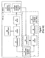
- Prior Art Figure 1 is a block diagram depicting the flow of data in accordance with a prior art data warehousing application.
- the model used to create a data mart capable of handling complex decision support queries is known as multi-dimensional modeling; one type of multi-dimensional model is called the "star schema.”
- a star schema is characterized by two types of tables: fact tables, and dimension tables.
- a fact table is where numerical measurements of a business are stored, taken at the intersection of the dimensions from one or more dimension tables.
- a fact table may include sales in dollars, number of units sold, total price, and the like.
- Dimension tables store the descriptions or characteristics of the business; dimension tables contain the descriptors of the facts. For example, product, customer, region, or time could be used as dimensions.
- a dimension table usually contains a primary key, and a fact table contains the foreign key.
- first target database 18 a slowly changing dimension table
- second target database 28 an aggregate fact table
- TLOG target load order group
- operational data are read from operational database 10, and the data are passed through aggregator 12, lookup 14 and filter 16 to identify and filter out duplicates of previously read data already stored in dimension table 18. Instances of data that are not duplicates are then added to dimension table 18.
- operational data are read from operational database 10, the operational data are passed through lookup 24 and aggregator 26 to transform the data into a format useful for decision support.
- dimension table 18 will contain customer names and a unique identifier (a "customer ID") associated with each name.
- Lookup cache 15a is built based on the information in dimension table 18 before execution of pipeline 1; specifically, lookup cache 15a is built from a persisted cache file from dimension table 18. Thus, lookup cache 15a will contain those customer names and/or the customer IDs already in dimension table 18 from the previous execution of the pipeline, before execution of pipeline 1.
- aggregator 12 Before updating dimension table 18, aggregator 12 functions to identify and combine duplicate instances of customer names in operational database 10.
- Lookup 14 compares the output from aggregator 12 against lookup cache 15a to identify new customer names. If the customer name appears in lookup cache 15a, then it is not a new name; in this case, filter 16 filters out the name so that it is not added to dimension table 18 (i.e., filter 16 filters out the rows in which the lookup value was found). If the name does not appear in lookup cache 15a, then it is a new name; in this case, the name is forwarded to dimension table 18. Sequence generator 17 then functions to automatically generate a customer ID (e.g., a primary key) for each new customer name.
- a customer ID e.g., a primary key
- lookup cache 15b is built by reading from dimension table 18 before pipeline 2 executes.
- Lookup cache 15a cannot be reused because, after it was built, dimension table 18 was updated with new customer names and IDs. Thus, dimension table 18 contains more recent information that is not contained in lookup cache 15a.
- Lookup cache 15b is built after execution of pipeline 1 but before the execution of pipeline 2, and thus will contain the information added to dimension table 18 in pipeline 1.
- Lookup 24 reads the customer IDs from lookup cache 15b, and aggregator 26 calculates the data for fact table 28. For example, aggregator 26 may calculate the total sales per customer. In this case, fact table 28 would contain the customer IDs and the total sales associated with each customer ID.
- operational database 10 is read twice, first to populate dimension table 18 in pipeline 1, and then to populate fact table 28 in pipeline 2.
- operational database 10 is very large (often on the order of 25 gigabytes), and so it can take several hours to read. Reading operational database 10 more than once also consumes valuable processing resources and decreases the speed at which data are transported and processed, decreasing data throughput. Additionally, it can impact negatively on the throughput of the transaction operating against the operational database.
- PRASAN SESHADRI, SHENOY, SUDAKSHAN: "Don't Trash your Intermediate Results, Cache'em” (TECHNICAL REPORT, [Online] 2 March 2000 (2000-03-02), pages 1-22, ITT Bombay) describes a facility, in a data warehousing application for the caching of result sets of a query, such that a future query including aspects of the cache report, can be served from the cache.
- OLAP on-line analytical processing
- Alex Rousskov, Duane Wessels "Cache Digests", 25-11-1998 describes a facility for caching web queries and results sets, to correct neighbour caches and thereby present a single view of a consistent cache.
- the present invention provides a method for processing data in a first data processing session in a data warehousing application, the method comprising the steps of:
- This method can increase data throughput, thereby increasing the speed at which data are transported and processed and reducing the load on the processing resources.
- Another embodiment of the invention provides a computer program product bearing computer executable instructions which, when loaded on a computer, cause said computer to perform the method of any of claims 1 to 7.
- Prior Art Figure 1 is a block diagram depicting the flow of data in data processing pipelines used in one embodiment of a prior art data warehousing application.
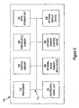
- FIG. 2 is a block diagram of an exemplary computer system used as part of a data warehousing system in accordance with one embodiment of the present invention.
- Figure 3 illustrates an exemplary data warehouse architecture that includes a transformation engine server in accordance with one embodiment of the present invention.
- Figure 4 is a block diagram depicting the flow of data in a data transport pipeline for a data warehouse application in accordance with one embodiment of the present invention.
- Figure 5 is a block diagram depicting the flow of data in a data transport pipeline for a data warehouse application in accordance with another embodiment of the present invention.
- Figure 6 is a flowchart of the steps in a process for synchronizing databases used in a data transport pipeline in accordance with one embodiment of the present invention.
- Data transport operations extract data from the source database, transform the data, and load the transformed data into a target database.
- data transport and “data transportation” as used herein include data extraction, transformation (processing), and loading.
- ''Target databases are data warehouses and/or data marts into which transformed data are loaded.
- one or more target databases are specified for storing the data generated by data transport "pipelines.”
- a “pipeline” as used herein refers to an architecture for data transport (e.g., data extraction, transformation, and storage).
- a “target load group order” (TLOG) refers to the set of target databases which are populated with transformed data from the same set of source databases; this term also can refer to the act of executing a pipeline. Accordingly, the execution of a pipeline or TLOG can load transformed data into one or more target databases.
- a “session” or “mapping” can include one or more pipelines or TLOGs. Multiple sessions can occur in parallel (e.g., multiple users executing pipelines in parallel) or in series.
- a pipeline structure is formed using a distributed architecture that packages source code such that the responsibility is distributed to smaller units (e.g., components) of source code.
- Each one of these software components is responsible for one specific type of transformation. Transformation components can be provided by the developer (e.g., from a monolithic transformation application) or can be user-developed. These transformation components form a base of ready-made elements that are combined to build functionally more sophisticated transformations in the data transportation process.
- the source transformation contains tables, views, synonyms, or flat files that provide data for the data mart/data warehouse.
- the target transformation maintains database objects or files that receive data from other transformations. These targets then make the data available to data mart users for decision support.
- Expression transformations calculate a single result, using values from one or more ports.
- the aggregation transformation calculates an aggregate value, such as a sum or average, using the entire range of data within a port or within a particular group. Filter transformations filter (selects) records based on a condition the user has set in the expression.
- the rank transformation filters the top or bottom range of records, based on a condition set by the user.
- the update strategy transformation assigns a numeric code to each record indicating whether the server should use the information in the record to insert, delete, or update the target.
- the sequence generator transformation generates unique ID numbers.
- the joiner transformation joins records from different databases or file systems.
- the lookup transformation looks up values.
- the stored procedure transformation calls a stored procedure.
- the external procedure transformation calls a procedure in a shared library or in the Component Object Model (COM) layer of Windows NT.
- the normalizer transformation normalizes records, including those read from virtual storage access method (VSAM) sources.
- VSAM virtual storage access method
- the source, target, aggregation, rank, and joiner transformations are all staged transformations.
- the lookup transformation also becomes a staged transformation when caching is turned on.
- the data generated by these transformations are automatically staged by the software, without human intervention.
- the expression, filter, update strategy, sequence, stored procedure, external procedure, and normalizer transformations are all streamed transformations. Other new types of transformations can also be added to this list.
- portions of the present invention are comprised of the computer-readable and computer-executable instructions which reside, for example, in computer system 110 used as a part of a data warehousing system in accordance with one embodiment of the present invention. It is appreciated that computer system 110 of Figure 2 is exemplary only and that the present invention can operate within a number of different computer systems including general-purpose computer systems, embedded computer systems, and stand-alone computer systems specially adapted for data warehousing applications.
- computer system 110 includes an address/data bus 112 for conveying digital information between the various components, a central processor unit (CPU) 114 for processing the digital information and instructions, a volatile main memory 116 comprised of volatile random access memory (RAM) for storing the digital information and instructions, and a non-volatile read only memory (ROM) 118 for storing information and instructions of a more permanent nature.
- CPU central processor unit
- RAM volatile random access memory
- ROM non-volatile read only memory
- computer system 110 may also include a data storage unit 120 (e.g., a magnetic, optical, floppy, or tape drive or the like) for storing vast amounts of data, and an input output (I/O) signal unit (e.g., interface) 122 for interfacing with peripheral devices (e.g., a computer network, modem, mass storage devices, etc.).
- data storage unit 120 e.g., a magnetic, optical, floppy, or tape drive or the like
- I/O signal unit e.g., interface
- peripheral devices e.g., a computer network, modem, mass storage devices, etc.
- the software program for performing the transport process of the present invention can be stored either in volatile memory 116, data storage unit 120, or in an external storage device (not shown).
- Devices which are optionally coupled to computer system 110 include a display device 128 for displaying information to a computer user, an alphanumeric input device 130 (e.g., a keyboard), and a cursor control device 126 (e.g., mouse, trackball, light pen, etc.) for inputting data, selections, updates, etc.
- a display device 128 for displaying information to a computer user
- an alphanumeric input device 130 e.g., a keyboard
- a cursor control device 126 e.g., mouse, trackball, light pen, etc.
- computer system 110 may be coupled in a network, such as in a client/server environment, whereby a number of clients (e.g., personal computers, workstations, portable computers, minicomputers, terminals, etc.) are used to run processes for performing desired tasks (e.g., inventory control, payroll, billing, etc.).
- clients e.g., personal computers, workstations, portable computers, minicomputers, terminals, etc.
- desired tasks e.g., inventory control, payroll, billing, etc.
- FIG. 3 illustrates an exemplary data warehouse architecture 200 upon which an embodiment of the present invention may be practiced.
- Operational databases 210, 220, and 230 store data resulting from business and financial transactions, and/or from equipment performance logs.
- These databases can be any of the conventional Relational Database Management Systems (RDBMS) (such as from Oracle, Informix, Sybase, Microsoft, etc.) that reside within a high capacity mass storage device (such as hard disk drives, optical drives, tape drives, etc.).
- Databases 250 and 260 are the data warehouses or data marts that are the targets of the data transportation process.
- Data integration engine 270 is a functional element that can be implemented in software and/or hardware for performing data transport operations.
- data integration engine 270 is a software program, operable on transformation engine server 240, that performs data transport operations. That is, in the present embodiment, data from databases 210, 220, and 230 are extracted, transformed, and loaded by transformation engine server 240 into databases 250 and 260.
- transformation engine server 240 can include multiple microprocessors which run an operating program (such as Windows NT, UNIX, or the like).
- Data integration engine 270 can extract data from source databases 210, 220, and 230 and store the extracted source data, when storage is required, in the memory storage of transformation engine server 240.
- Figure 4 is a block diagram depicting the flow of data in data transport pipelines 400 and 405 in accordance with one embodiment of the present invention.
- pipelines 400 and 405 are used in a data warehousing application.
- Pipelines 400 and 405 are exemplary; additional databases and transformations may be included in accordance with the present invention.
- pipeline 400 e.g., a first TLOG
- first target database e.g., dimension table 418
- second target database e.g., fact table 428
- Pipelines 400 and 405 can both be executed in a single session or mapping.
- Dimension table 418 and fact table 428 can also reside in a same target database (that is, the first and second target databases could be the same database, but different physical tables).
- operational data are read from operational database 410.
- Dynamic lookup 414 is performed using lookup cache 415, and filter 416 identifies and filters out duplicates of previously read data already stored in dimension table 418. Instances of data that are not duplicates are then added to dimension table 418 and also to lookup cache 415.
- operational data are read from operational database 410, and static lookup 420 is performed using lookup cache 415.
- the data are passed through aggregator 426 to transform the data into a format useful for decision support, trend analysis, and the like, and then added to fact table 428.
- operational database 410 is read from twice.
- the same lookup cache 415 is used in both pipeline 400 and in pipeline 405.
- the lookup cache used in pipeline 400 does not need to be rebuilt for pipeline 405, and therefore data processing can be more quickly completed using less computational resources.
- the data in lookup cache 415 are synchronized with the data in dimension table 418, so that lookup cache 415 includes information added to dimension table 418. That is, in accordance with the present invention, when dimension table 418 is updated, lookup cache 415 is also updated. Lookup cache 415 can then be used to populate fact table 428. In accordance with the present embodiment of the present invention, it is not necessary to re-initialize lookup cache 415 before executing pipeline 405.
- multiple dimension tables can describe one fact table, or the same dimension table can be used to describe multiple fact tables
- additional pipelines with dimension tables, lookup caches and fact tables can be appended to pipelines 400 and 405 in accordance with the present invention, depending on the particular data characteristics and descriptors that are to be used and the type of information desired for the data warehouse/mart. In addition, this would allow population of a star schema multi-dimensional model.
- the descriptor (dimension) of interest is the customer name and the fact of interest is the sales per customer.
- dimension table 418 will contain customer names and a unique identifier (a "primary key" such as a "customer ID") associated with each name. Subsequently, new transactions (e.g., customer purchases) occur and so new data are added to operational database 410. In fact, a customer may make several purchases, and so the customer's name may appear several times in operational database 410.
- a unique identifier such as a "customer ID”
- a lookup 414 is performed to compare the output from source 410 to lookup cache 415 to identify new customer names.
- the user specifies whether the lookup 414 is dynamic or not.
- lookup cache 415 is synchronized with dimension table 418, and therefore lookup cache 415 contains the same customer names as dimension table 418.
- lookup 414 if lookup 414 is dynamic, there is an additional output port (O), and each lookup port (L) will either be associated with an input port (I) or specified as the sequence ID port.
- Table 1 below provides an exemplary port specification in accordance with one embodiment of the present invention. In this embodiment, for dynamic lookups, the column entitled “Associated Port for Lookup Updates” is enabled and the default output column "NewLookupRow” is used.
- Table 1 Exemplary Port Specification for Dynamic Lookups Port Name Data Type Associated Port for Lookup Updates I O L NewLookupRow integer n/a x InCustName string n/a x InCustAddress string n/a x LkupCustName string InCustName x x LkupCustAddress string InCustAddress x x LkupCustld integer sequenceID x x
- NewLookupRow will output an integer value of 1 (one) if the current input row is not found in lookup cache 415 and is to be inserted into lookup cache 415. NewLookupRow will output an integer value of 0 (zero) if the current input row is found in lookup cache 415. If a new lookup row is added to lookup cache 415, any subsequent references to that lookup row are considered to be found. Hence, the NewLookupRow port will return 0 (zero) for subsequent rows with the same lookup key.
- an associated input port or the sequenceID indicator is specified and inserted into lookup cache 415 when a row cannot be found.
- the output value will be exactly what is being inserted into lookup cache 415.
- dimension table 418 when a new row is inserted into dimension table 418, a new primary key is generated using an internal sequence generator (not shown), and the new row and key are inserted in lookup cache 415.
- dimension table 418 and lookup cache 415 are synchronized and comprise the same information.
- lookup cache 415 If the customer's name appears in lookup cache 415, then it is not a new name; in this case, filter 416 filters out the name so that it is not added to dimension table 418. If the name does not appear in lookup cache 415, then it is a new name; in this case, lookup cache 415 is updated and the name is added to dimension table 418.
- a customer ID e.g., a primary key
- lookup cache 415 is persisted (saved) so that it can be used in pipeline 405.
- operational database 410 is read again.
- Customer IDs needed for fact table 428 are read from lookup cache 415 in static lookup 420.
- Static lookup 420 uses the persisted lookup cache 415 from pipeline 400.
- lookup cache 415 can be used in pipeline 405 because it has been updated with hew customer names and IDs.
- Aggregator 426 calculates the data for fact table 428; for example, aggregator 426 may calculate the total sales per customer. In this case, fact table 428 would contain the customer names, customer IDs and the total sales associated with each customer ID.
- lookup cache 415 can be shared across different sessions (e.g., mappings) and different pipelines (e.g., different TLOGs).
- the persisted lookup cache 415 e.g., from pipeline 400
- an identifying attribute such as a file name.
- a user can specify the attribute in order to use the same lookup cache in multiple sessions or mappings. If no file name is specified, or if the cache cannot be found, a new lookup cache will be created.
- FIG. 5 is a block diagram depicting the flow of data in a data transport pipeline 500 in accordance with one embodiment of the present invention.
- pipeline 500 is used in a data warehousing application.
- a single data transport pipeline 500 is used to populate a dimension table (first target database 418) and a fact table (second target database 428) with information from a source (operational database 410).
- Dynamic lookup 514 can be used with filter 416 to filter out duplicates of previously read data already stored in dimension table 418, and dynamic lookup 514 can also be used to find, for example, customer IDs needed for fact table 428.
- dynamic lookup 514 is performed instead of dynamic lookup 414 and static lookup 420.
- FIG 6 is a flowchart of the steps in a process 600 for synchronizing databases used in a data transport pipeline (e.g., pipelines 400 and 405 of Figure 4, or pipeline 500 of Figure 5) in accordance with one embodiment of the present invention.
- Process 600 can be implemented via computer-readable program instructions stored in a memory unit (e.g., volatile memory 116, non-volatile memory 118, and/or data storage unit 120) and executed by processor 114 of computer system 110 ( Figure 2).
- a memory unit e.g., volatile memory 116, non-volatile memory 118, and/or data storage unit 120
- processor 114 of computer system 110 Figure 2
- portions of pipelines 400, 405 and 500 can reside on different computer systems that are communicatively linked.
- operational database 410 can reside on one computer system, dimension table 418 on the same computer system or a different one, and fact table 428 on one of these computer systems or still another one. Also, as explained above, it is appreciated that lookup cache 415 can be shared across multiple sessions.
- step 610 of Figure 6 operational data are received from a source (e.g., operational database 410).
- a source e.g., operational database 410
- data are read row-by-row and processed through the data transport pipeline.
- step 620 the operational data are compared against a lookup cache (e.g., lookup cache 415 of Figures 4 and 5) to identify any instances in which an entry in the operational data is already present in a first target database (e.g., dimension table 418 of Figures 4 and 5).
- a lookup cache e.g., lookup cache 415 of Figures 4 and 5
- the data in the lookup cache and the data in the first target data base are synchronized.
- the lookup cache can contain those customer names already in the first target database.
- step 625 of Figure 6 if there are no new instances of operational data, then process 600 proceeds to step 660. Otherwise, process 600 proceeds to step 630.
- a unique identifier (e.g., a primary key) is generated for and associated with each instance of new dimensional data using, for example, a sequence generator. It is appreciated that other information may be generated for and associated with each new instance of dimensional data.
- the lookup cache (e.g., lookup cache 415 of Figure 4) and the first target database (e.g., dimension table 418 of Figure 4) are each updated.
- the lookup cache is dynamic and in synchronization with the first target database.
- a second target database (e.g., fact table 428 of Figure 4) can be generated or updated (depending on whether it was previously initialized in a prior execution of the data transport pipeline) using the operational database information and the information from the first target database.
- the second target database is updated in a single session comprising two pipelines (two TLOGS), as shown by Figure 4.
- the second target database is updated in a single session comprising a single pipeline (one TLOG), as shown by Figure 5.
- the dimension table and the lookup cache are synchronized so that the lookup cache can be updated during a session run.
- operational data do not need to be aggregated to combine duplicate data before doing the lookup (e.g., an aggregation step before dynamic lookup 414 and 514 of Figures 4 and 5, respectively, is not needed). Instead, this aggregation is performed automatically because, once an entry is inserted into dynamic cache, it is considered to be found, and subsequent rows of data will have the NewLookupRow set to zero (see discussion pertaining to Table 1, above). Accordingly, one stage in the data transport pipeline (and the associated memory and processing) can be eliminated in accordance with the present invention.
- a single data transport pipeline can be used to populate both the dimension table and a fact table during a session run. Accordingly, in this embodiment, it is only necessary to access and read an operational database one time during a session, which can reduce the processing time by up to one-half.
- the present invention therefore provides a method that can increase data throughput, thereby increasing the speed at which data are transported and processed.
- the present invention also provides a method that can reduce the load on processing resources.
- the present invention provides a method that can be used in a data warehouse system.
Landscapes
- Engineering & Computer Science (AREA)
- Theoretical Computer Science (AREA)
- Data Mining & Analysis (AREA)
- Databases & Information Systems (AREA)
- Physics & Mathematics (AREA)
- General Engineering & Computer Science (AREA)
- General Physics & Mathematics (AREA)
- Information Retrieval, Db Structures And Fs Structures Therefor (AREA)
- Hardware Redundancy (AREA)
- Information Transfer Between Computers (AREA)
- Photoreceptors In Electrophotography (AREA)
Abstract
Description
- The present disclosure relates to data management systems. More particularly, the present disclosure pertains to a method for synchronizing data in a data warehousing application. The disclosure discusses a method for synchronizing cache with target tables in a data warehousing system.
- Due to the increased amounts of data being stored and processed today, operational databases are constructed, categorized, and formatted for operational efficiency (e.g., throughput, processing speed, and storage capacity). Unfortunately, the raw data found in these operational databases often exist as rows and columns of numbers and code which appear bewildering and incomprehensible to business analysts and decision makers. Furthermore, the scope and vastness of the raw data stored in modern databases render it harder to analyze. Hence, applications were developed in an effort to help interpret, analyze, and compile the data so that a business analyst may readily understand it. This is accomplished by mapping, sorting, and summarizing the raw data before it is presented for display. Thereby, individuals can now interpret the data and make key decisions based thereon.
- Extracting raw data from one or more operational databases and transforming it into useful information is the function of data "warehouses" and data "marts." In data warehouses and data marts, the data are structured to satisfy decision support roles. Before the data are loaded into the target data warehouse or data mart, the corresponding source data from an operational database are filtered to remove extraneous and erroneous records; cryptic and conflicting codes are resolved; raw data are translated into something more meaningful; and summary data that are useful for decision support, trend analysis or other end-user needs are pre-calculated.
- The data warehouse is comprised of an analytical database containing data useful for decision support. The warehouse contains data from multiple sources and formats. Data are extracted from the sources, transformed as needed, and mapped into the warehouse. A data mart is similar to a data warehouse, except that it contains a subset of corporate data for a single aspect of business, such as finance, sales, inventory, or human resources. With data warehouses and data marts, useful information is retained at the disposal of the decision-makers.
- One major difficulty associated with implementing data warehouses and data marts relates to that of transporting data, non-invasively and in a timely manner, from the operational databases to the data warehouses and/or data marts. As new transactions occur, vast amounts of new data are generated and added to the operational databases. If the new data are not transported to the data warehouse/mart databases by the time of analysis, these databases are out of sync with the operational databases. Consequently, the data within the data warehouses/marts lose their relevance for the analyses used in support of the decision-makers.
- To maintain the relevance of the decision-making analyses, and to quickly capture the rich data patterns and information contained in the operational databases, frequent refreshes of the data warehouses/marts are preferred. However, operational databases are very large to begin with, and they can rapidly grow larger as new data are accumulated. As a result, data transport processes (data extraction, transformation, and loading) can consume a significant amount of system resources and take a long time to complete. Thus, it is desirable to find approaches for non-invasive data transport that can increase the throughput and speed of the data transporting process.
- Prior Art Figure 1 is a block diagram depicting the flow of data in accordance with a prior art data warehousing application. The model used to create a data mart capable of handling complex decision support queries is known as multi-dimensional modeling; one type of multi-dimensional model is called the "star schema." A star schema is characterized by two types of tables: fact tables, and dimension tables. In a data warehousing application, a fact table is where numerical measurements of a business are stored, taken at the intersection of the dimensions from one or more dimension tables. For example, a fact table may include sales in dollars, number of units sold, total price, and the like. Dimension tables store the descriptions or characteristics of the business; dimension tables contain the descriptors of the facts. For example, product, customer, region, or time could be used as dimensions. A dimension table usually contains a primary key, and a fact table contains the foreign key.
- With reference still to Figure 1, for many applications, in particular electronic business ("e-business") applications, a slowly changing dimension table (first target database 18) and an aggregate fact table (second target database 28) are both populated with information from a same source (operational database 10). Currently, this is accomplished by first populating dimension table 18 with one target load order group (TLOG) (e.g., pipeline 1) and then populating fact table 28 with another TLOG (e.g., pipeline 2).
- In pipeline 1, operational data are read from
operational database 10, and the data are passed throughaggregator 12,lookup 14 andfilter 16 to identify and filter out duplicates of previously read data already stored in dimension table 18. Instances of data that are not duplicates are then added to dimension table 18. In pipeline 2, operational data are read fromoperational database 10, the operational data are passed throughlookup 24 andaggregator 26 to transform the data into a format useful for decision support. - An example will be used to provide a further description of pipelines 1 and 2. From a previous execution of a pipeline, dimension table 18 will contain customer names and a unique identifier (a "customer ID") associated with each name.
Lookup cache 15a is built based on the information in dimension table 18 before execution of pipeline 1; specifically,lookup cache 15a is built from a persisted cache file from dimension table 18. Thus,lookup cache 15a will contain those customer names and/or the customer IDs already in dimension table 18 from the previous execution of the pipeline, before execution of pipeline 1. - When new transactions (e.g., customer purchases) occur, new data will be added to
operational database 10. In fact, a customer may make several purchases, and so the customer's name may appear several times inoperational database 10. Pipelines 1 and 2 therefore need to be executed in order to update dimension table 18 and fact table 28, respectively, with the new data inoperational database 10. - If the customer's name and associated customer ID are not already in dimension table 18, then it is necessary to assign a customer ID and add the name and the ID to dimension table 18. However, if the customer's name and ID are already in dimension table 18, then this is not necessary. In addition, it is not necessary or desirable to assign a customer ID to each of the multiple instances in which the customer's name appears in
operational database 10. - Before updating dimension table 18,
aggregator 12 functions to identify and combine duplicate instances of customer names inoperational database 10. Lookup 14 compares the output fromaggregator 12 againstlookup cache 15a to identify new customer names. If the customer name appears inlookup cache 15a, then it is not a new name; in this case, filter 16 filters out the name so that it is not added to dimension table 18 (i.e., filter 16 filters out the rows in which the lookup value was found). If the name does not appear inlookup cache 15a, then it is a new name; in this case, the name is forwarded to dimension table 18.Sequence generator 17 then functions to automatically generate a customer ID (e.g., a primary key) for each new customer name. - To populate fact table 28 in pipeline 2,
operational database 10 is read again. To get the customer IDs needed for fact table 28, anew lookup cache 15b is built by reading from dimension table 18 before pipeline 2 executes.Lookup cache 15a cannot be reused because, after it was built, dimension table 18 was updated with new customer names and IDs. Thus, dimension table 18 contains more recent information that is not contained inlookup cache 15a.Lookup cache 15b is built after execution of pipeline 1 but before the execution of pipeline 2, and thus will contain the information added to dimension table 18 in pipeline 1. - Lookup 24 reads the customer IDs from
lookup cache 15b, andaggregator 26 calculates the data for fact table 28. For example,aggregator 26 may calculate the total sales per customer. In this case, fact table 28 would contain the customer IDs and the total sales associated with each customer ID. - The prior art is problematic because, as described above, after the execution of pipeline 1 the dimension table 18 will contain more recent information (e.g., new customer name and customer IDs) than that contained in
lookup cache 15a. As a result, it is necessary to re-initializelookup cache 15a (that is, buildlookup cache 15b) before populating fact table 28 (before executing pipeline 2). That is, any updates to the dimension table require that the lookup cache be rebuilt.Caches - Another problem with the prior art is that
operational database 10 is read twice, first to populate dimension table 18 in pipeline 1, and then to populate fact table 28 in pipeline 2. As described above,operational database 10 is very large (often on the order of 25 gigabytes), and so it can take several hours to read. Readingoperational database 10 more than once also consumes valuable processing resources and decreases the speed at which data are transported and processed, decreasing data throughput. Additionally, it can impact negatively on the throughput of the transaction operating against the operational database. - Potential solutions for addressing these problems are complicated by the use of different processes in different portions of the pipeline. For example, in the PowerMart Suite by Informatica of Palo Alto, California, a Data Transformation Manager (DTM) manages one portion of pipeline 1, and a Writer process is launched for another portion of pipeline 1, as illustrated in Figure 1.
- PRASAN, SESHADRI, SHENOY, SUDAKSHAN: "Don't Trash your Intermediate Results, Cache'em" (TECHNICAL REPORT, [Online] 2 March 2000 (2000-03-02), pages 1-22, ITT Bombay) describes a facility, in a data warehousing application for the caching of result sets of a query, such that a future query including aspects of the cache report, can be served from the cache.
- CHAUDHURIS ET AL: "An overview of Data Warehousing and OLAP Technology" (SIGMOD RECORD, SIGMOD, NEW YORK, NY US, vol. 26, no. 1 March 1997 (1997-03), pages 65-74, ISSN: 0163-5808) describes the use of data warehousing in background terms, but is mostly concerned with on-line analytical processing (OLAP).
- Mesaac Makpangou, Guillaume Pierre "Replicated Directory Service for Weakly Consistent Distributed Caches", 31-05-1999 describes a facility, in a data processing system, for maintaining a directory of contents of information providers, in a cache of results sets of query data.
- Alex Rousskov, Duane Wessels "Cache Digests", 25-11-1998 describes a facility for caching web queries and results sets, to correct neighbour caches and thereby present a single view of a consistent cache.
- Accordingly, what is needed is a method and/or apparatus that can increase the speed at which data are transported and processed, and reduce the load on processing resources. What is also needed is a method and/or apparatus that can satisfy the above needs and that can be adapted for use in a data warehouse system.
- The present invention provides a method for processing data in a first data processing session in a data warehousing application, the method comprising the steps of:
- receiving operational data from a source table of the data warehousing application;
- identifying an instance of the operational data not present in a lookup cache;
- updating the lookup cache to include the instance so that the lookup cache includes updated data;
- updating a first target table of the data warehousing application to include the instance so that data in the lookup cache and data in the first target table are synchronous; and
- generating information for a second target table of the data warehousing application using the updated data from the lookup cache.
- This method can increase data throughput, thereby increasing the speed at which data are transported and processed and reducing the load on the processing resources.
- Another embodiment of the invention provides a computer program product bearing computer executable instructions which, when loaded on a computer, cause said computer to perform the method of any of claims 1 to 7.
- The accompanying drawings, which are incorporated in and form a part of this specification, illustrate embodiments of the present invention and, together with the description, serve to explain the principles of the invention.
- Prior Art Figure 1 is a block diagram depicting the flow of data in data processing pipelines used in one embodiment of a prior art data warehousing application.
- Figure 2 is a block diagram of an exemplary computer system used as part of a data warehousing system in accordance with one embodiment of the present invention.
- Figure 3 illustrates an exemplary data warehouse architecture that includes a transformation engine server in accordance with one embodiment of the present invention.
- Figure 4 is a block diagram depicting the flow of data in a data transport pipeline for a data warehouse application in accordance with one embodiment of the present invention.
- Figure 5 is a block diagram depicting the flow of data in a data transport pipeline for a data warehouse application in accordance with another embodiment of the present invention.
- Figure 6 is a flowchart of the steps in a process for synchronizing databases used in a data transport pipeline in accordance with one embodiment of the present invention.
- An apparatus and method for synchronizing data in a data management system are described. In particular, an apparatus and method for synchronizing data in a cache with data in a target table in a data warehousing system are described. In the following description, for purposes of explanation, numerous specific details are set forth in order to provide a thorough understanding of the present invention. It will be obvious, however, to one skilled in the art that the present invention may be practiced without these specific details. In other instances, well-known structures and devices are shown in block diagram form in order to avoid obscuring the present invention.
- Some portions of the detailed descriptions that follow are presented in terms of procedures, logic blocks, processing, and other symbolic representations of operations on data bits within a computer memory. These descriptions and representations are the means used by those skilled in the data processing arts to most effectively convey the substance of their work to others skilled in the art. In the present application, a procedure, logic block, process, etc., is conceived to be a self-consistent sequence of steps or instructions leading to a desired result. The steps are those requiring physical manipulations of physical quantities. Usually, though not necessarily, these quantities take the form of electrical or magnetic signals capable of being stored, transferred, combined, compared, and otherwise manipulated in a computer system. It has proven convenient at times, principally for reasons of common usage, to refer to these signals as bits, values, elements, symbols, characters, terms, numbers, or the like.
- It should be borne in mind, however, that all of these and similar terms are to be associated with the appropriate physical quantities and are merely convenient labels applied to these quantities. Unless specifically stated otherwise as apparent from the following discussions, it is appreciated that throughout the present invention, discussions utilizing terms such as "identifying," "updating," "associating," "storing," "receiving," "generating," "performing" or the like, can refer to the actions and processes (e.g.,
process 600 of Figure 6) of a computer system or similar electronic computing device. The computer system or similar electronic computing device manipulates and transforms data represented as physical (electronic) quantities within the computer system's registers and memories into other data similarly represented as physical quantities within the computer system memories or registers or other such information storage, transmission, or display devices. - Data transport operations extract data from the source database, transform the data, and load the transformed data into a target database. The terms "data transport" and "data transportation" as used herein include data extraction, transformation (processing), and loading.
- ''Target databases" (or "target tables") are data warehouses and/or data marts into which transformed data are loaded. In the present embodiment, one or more target databases are specified for storing the data generated by data transport "pipelines."
- The term "pipeline" as used herein refers to an architecture for data transport (e.g., data extraction, transformation, and storage). A "target load group order" (TLOG) refers to the set of target databases which are populated with transformed data from the same set of source databases; this term also can refer to the act of executing a pipeline. Accordingly, the execution of a pipeline or TLOG can load transformed data into one or more target databases. A "session" or "mapping" can include one or more pipelines or TLOGs. Multiple sessions can occur in parallel (e.g., multiple users executing pipelines in parallel) or in series.
- A pipeline structure is formed using a distributed architecture that packages source code such that the responsibility is distributed to smaller units (e.g., components) of source code. Each one of these software components is responsible for one specific type of transformation. Transformation components can be provided by the developer (e.g., from a monolithic transformation application) or can be user-developed. These transformation components form a base of ready-made elements that are combined to build functionally more sophisticated transformations in the data transportation process.
- The transformation components are then coupled together to form the pipeline structure. Further information regarding the use of coupled transformation components to form pipelines is described in the U.S. Patent Application entitled "Method and Architecture for Automated Optimization of ETL Throughput in Data Warehousing Applications," with Serial Number 09/116,426 and filing date July 15, 1998, assigned to the assignee of the present invention and hereby incorporated by reference.
- In one embodiment, there are thirteen different transformation components: source, target, expression, aggregation, filter, rank, update strategy, sequence, joiner, lookup, stored procedure, external procedure, and normalizer. The source transformation contains tables, views, synonyms, or flat files that provide data for the data mart/data warehouse. The target transformation maintains database objects or files that receive data from other transformations. These targets then make the data available to data mart users for decision support. Expression transformations calculate a single result, using values from one or more ports. The aggregation transformation calculates an aggregate value, such as a sum or average, using the entire range of data within a port or within a particular group. Filter transformations filter (selects) records based on a condition the user has set in the expression. The rank transformation filters the top or bottom range of records, based on a condition set by the user. The update strategy transformation assigns a numeric code to each record indicating whether the server should use the information in the record to insert, delete, or update the target. The sequence generator transformation generates unique ID numbers. The joiner transformation joins records from different databases or file systems. The lookup transformation looks up values. The stored procedure transformation calls a stored procedure. The external procedure transformation calls a procedure in a shared library or in the Component Object Model (COM) layer of Windows NT. The normalizer transformation normalizes records, including those read from virtual storage access method (VSAM) sources.
- In the present embodiment, the source, target, aggregation, rank, and joiner transformations are all staged transformations. The lookup transformation also becomes a staged transformation when caching is turned on. The data generated by these transformations are automatically staged by the software, without human intervention. The expression, filter, update strategy, sequence, stored procedure, external procedure, and normalizer transformations are all streamed transformations. Other new types of transformations can also be added to this list.
- With reference to Figure 2, portions of the present invention are comprised of the computer-readable and computer-executable instructions which reside, for example, in
computer system 110 used as a part of a data warehousing system in accordance with one embodiment of the present invention. It is appreciated thatcomputer system 110 of Figure 2 is exemplary only and that the present invention can operate within a number of different computer systems including general-purpose computer systems, embedded computer systems, and stand-alone computer systems specially adapted for data warehousing applications. - In the present embodiment,
computer system 110 includes an address/data bus 112 for conveying digital information between the various components, a central processor unit (CPU) 114 for processing the digital information and instructions, a volatilemain memory 116 comprised of volatile random access memory (RAM) for storing the digital information and instructions, and a non-volatile read only memory (ROM) 118 for storing information and instructions of a more permanent nature. In addition,computer system 110 may also include a data storage unit 120 (e.g., a magnetic, optical, floppy, or tape drive or the like) for storing vast amounts of data, and an input output (I/O) signal unit (e.g., interface) 122 for interfacing with peripheral devices (e.g., a computer network, modem, mass storage devices, etc.). It should be noted that the software program for performing the transport process of the present invention can be stored either involatile memory 116,data storage unit 120, or in an external storage device (not shown). - Devices which are optionally coupled to
computer system 110 include adisplay device 128 for displaying information to a computer user, an alphanumeric input device 130 (e.g., a keyboard), and a cursor control device 126 (e.g., mouse, trackball, light pen, etc.) for inputting data, selections, updates, etc. - Furthermore,
computer system 110 may be coupled in a network, such as in a client/server environment, whereby a number of clients (e.g., personal computers, workstations, portable computers, minicomputers, terminals, etc.) are used to run processes for performing desired tasks (e.g., inventory control, payroll, billing, etc.). - Figure 3 illustrates an exemplary
data warehouse architecture 200 upon which an embodiment of the present invention may be practiced.Operational databases Databases 250 and 260 (targets A and B, respectively) are the data warehouses or data marts that are the targets of the data transportation process. -
Data integration engine 270 is a functional element that can be implemented in software and/or hardware for performing data transport operations. In the present embodiment,data integration engine 270 is a software program, operable ontransformation engine server 240, that performs data transport operations. That is, in the present embodiment, data fromdatabases transformation engine server 240 intodatabases transformation engine server 240 can include multiple microprocessors which run an operating program (such as Windows NT, UNIX, or the like).Data integration engine 270 can extract data fromsource databases transformation engine server 240. - Figure 4 is a block diagram depicting the flow of data in
data transport pipelines pipelines Pipelines - In the present embodiment, pipeline 400 (e.g., a first TLOG) is used to populate a first target database (e.g., dimension table 418), and pipeline 405 (e.g., a second TLOG) is used to populate a second target database (e.g., fact table 428).
Pipelines - In
pipeline 400, operational data are read fromoperational database 410.Dynamic lookup 414 is performed usinglookup cache 415, and filter 416 identifies and filters out duplicates of previously read data already stored in dimension table 418. Instances of data that are not duplicates are then added to dimension table 418 and also tolookup cache 415. - In
pipeline 405, operational data are read fromoperational database 410, andstatic lookup 420 is performed usinglookup cache 415. The data are passed throughaggregator 426 to transform the data into a format useful for decision support, trend analysis, and the like, and then added to fact table 428. - In the present embodiment,
operational database 410 is read from twice. However, in accordance with the present invention, thesame lookup cache 415 is used in bothpipeline 400 and inpipeline 405. As will be seen, the lookup cache used inpipeline 400 does not need to be rebuilt forpipeline 405, and therefore data processing can be more quickly completed using less computational resources. - In accordance with the present embodiment of the present invention, the data in
lookup cache 415 are synchronized with the data in dimension table 418, so thatlookup cache 415 includes information added to dimension table 418. That is, in accordance with the present invention, when dimension table 418 is updated,lookup cache 415 is also updated.Lookup cache 415 can then be used to populate fact table 428. In accordance with the present embodiment of the present invention, it is not necessary to re-initializelookup cache 415 before executingpipeline 405. - Because, in practice, multiple dimension tables can describe one fact table, or the same dimension table can be used to describe multiple fact tables, additional pipelines with dimension tables, lookup caches and fact tables (not shown) can be appended to
pipelines - With reference still to Figure 4, an example application is used to provide a further description of the features of the present embodiment of the present invention. In this example, the descriptor (dimension) of interest is the customer name and the fact of interest is the sales per customer.
- From a previous execution of
pipeline 400, dimension table 418 will contain customer names and a unique identifier (a "primary key" such as a "customer ID") associated with each name. Subsequently, new transactions (e.g., customer purchases) occur and so new data are added tooperational database 410. In fact, a customer may make several purchases, and so the customer's name may appear several times inoperational database 410. - If the customer's name and associated customer ID are not already in dimension table 418, then it is necessary to assign a customer ID and add the name and the ID to dimension table 418. However, if the customer's name and ID are already in dimension table 418, then this is not necessary. In addition, it is not necessary or desirable to assign a customer ID to each of the multiple instances in which the customer's name appears in
operational database 410. - A
lookup 414 is performed to compare the output fromsource 410 tolookup cache 415 to identify new customer names. In one embodiment, the user specifies whether thelookup 414 is dynamic or not. For a dynamic lookup, in accordance with the present invention,lookup cache 415 is synchronized with dimension table 418, and thereforelookup cache 415 contains the same customer names as dimension table 418. - In one embodiment, if
lookup 414 is dynamic, there is an additional output port (O), and each lookup port (L) will either be associated with an input port (I) or specified as the sequence ID port. Table 1 below provides an exemplary port specification in accordance with one embodiment of the present invention. In this embodiment, for dynamic lookups, the column entitled "Associated Port for Lookup Updates" is enabled and the default output column "NewLookupRow" is used.Table 1: Exemplary Port Specification for Dynamic Lookups Port Name Data Type Associated Port for Lookup Updates I O L NewLookupRow integer n/a x InCustName string n/a x InCustAddress string n/a x LkupCustName string InCustName x x LkupCustAddress string InCustAddress x x LkupCustld integer sequenceID x x - In the embodiment of Table 1, NewLookupRow will output an integer value of 1 (one) if the current input row is not found in
lookup cache 415 and is to be inserted intolookup cache 415. NewLookupRow will output an integer value of 0 (zero) if the current input row is found inlookup cache 415. If a new lookup row is added tolookup cache 415, any subsequent references to that lookup row are considered to be found. Hence, the NewLookupRow port will return 0 (zero) for subsequent rows with the same lookup key. - In the present embodiment, for each lookup port, an associated input port or the sequenceID indicator is specified and inserted into
lookup cache 415 when a row cannot be found. For a lookup port marked as an output port, the output value will be exactly what is being inserted intolookup cache 415. - In accordance with the present embodiment of the present invention, when a new row is inserted into dimension table 418, a new primary key is generated using an internal sequence generator (not shown), and the new row and key are inserted in
lookup cache 415. Thus, in accordance with the present invention, dimension table 418 andlookup cache 415 are synchronized and comprise the same information. - If the customer's name appears in
lookup cache 415, then it is not a new name; in this case, filter 416 filters out the name so that it is not added to dimension table 418. If the name does not appear inlookup cache 415, then it is a new name; in this case,lookup cache 415 is updated and the name is added to dimension table 418. A customer ID (e.g., a primary key) is associated with each customer name inlookup cache 415 and dimension table 418. - After
pipeline 400 is executed,lookup cache 415 is persisted (saved) so that it can be used inpipeline 405. Inpipeline 405,operational database 410 is read again. Customer IDs needed for fact table 428 are read fromlookup cache 415 instatic lookup 420.Static lookup 420 uses the persistedlookup cache 415 frompipeline 400. In accordance with the present invention,lookup cache 415 can be used inpipeline 405 because it has been updated with hew customer names and IDs.Aggregator 426 calculates the data for fact table 428; for example,aggregator 426 may calculate the total sales per customer. In this case, fact table 428 would contain the customer names, customer IDs and the total sales associated with each customer ID. - In accordance with the present invention,
lookup cache 415 can be shared across different sessions (e.g., mappings) and different pipelines (e.g., different TLOGs). In one embodiment, the persisted lookup cache 415 (e.g., from pipeline 400) is assigned an identifying attribute such as a file name. When performing a different session or mapping, a user can specify the attribute in order to use the same lookup cache in multiple sessions or mappings. If no file name is specified, or if the cache cannot be found, a new lookup cache will be created. - Figure 5 is a block diagram depicting the flow of data in a
data transport pipeline 500 in accordance with one embodiment of the present invention. In the preferred embodiment,pipeline 500 is used in a data warehousing application. - In the present embodiment, a single
data transport pipeline 500 is used to populate a dimension table (first target database 418) and a fact table (second target database 428) with information from a source (operational database 410).Dynamic lookup 514 can be used withfilter 416 to filter out duplicates of previously read data already stored in dimension table 418, anddynamic lookup 514 can also be used to find, for example, customer IDs needed for fact table 428. Thus, relative to Figure 4,dynamic lookup 514 is performed instead ofdynamic lookup 414 andstatic lookup 420. - Thus, in accordance with the present embodiment of the present invention, it is only necessary to access and read
operational database 410 one time. In addition, it is only necessary to maintain asingle lookup cache 415 and to read the lookup cache one time (e.g., dynamic lookup 514). Consequently, data throughput is increased, thereby increasing the speed at which data are transported and processed. In addition, the load on processing resources is reduced (e.g., computer resources such as processor cycles and memory). - Figure 6 is a flowchart of the steps in a
process 600 for synchronizing databases used in a data transport pipeline (e.g.,pipelines pipeline 500 of Figure 5) in accordance with one embodiment of the present invention.Process 600 can be implemented via computer-readable program instructions stored in a memory unit (e.g.,volatile memory 116,non-volatile memory 118, and/or data storage unit 120) and executed byprocessor 114 of computer system 110 (Figure 2). However, it is appreciated that portions ofpipelines operational database 410 can reside on one computer system, dimension table 418 on the same computer system or a different one, and fact table 428 on one of these computer systems or still another one. Also, as explained above, it is appreciated thatlookup cache 415 can be shared across multiple sessions. - In
step 610 of Figure 6, operational data are received from a source (e.g., operational database 410). In the present embodiment, data are read row-by-row and processed through the data transport pipeline. - In
step 620, the operational data are compared against a lookup cache (e.g.,lookup cache 415 of Figures 4 and 5) to identify any instances in which an entry in the operational data is already present in a first target database (e.g., dimension table 418 of Figures 4 and 5). In accordance with the present invention, the data in the lookup cache and the data in the first target data base are synchronized. For example, the lookup cache can contain those customer names already in the first target database. Thus, when the operational data are compared to the lookup cache, any instances of "dimensional" data (e.g., a customer name) not in the lookup cache must be new. - In
step 625 of Figure 6, if there are no new instances of operational data, then process 600 proceeds to step 660. Otherwise,process 600 proceeds to step 630. - In
step 630, a unique identifier (e.g., a primary key) is generated for and associated with each instance of new dimensional data using, for example, a sequence generator. It is appreciated that other information may be generated for and associated with each new instance of dimensional data. - In
steps lookup cache 415 of Figure 4) and the first target database (e.g., dimension table 418 of Figure 4) are each updated. In accordance with the present invention, the lookup cache is dynamic and in synchronization with the first target database. - In
step 660, a second target database (e.g., fact table 428 of Figure 4) can be generated or updated (depending on whether it was previously initialized in a prior execution of the data transport pipeline) using the operational database information and the information from the first target database. In one embodiment, the second target database is updated in a single session comprising two pipelines (two TLOGS), as shown by Figure 4. In another embodiment, the second target database is updated in a single session comprising a single pipeline (one TLOG), as shown by Figure 5. - In summary, in accordance with the present invention, the dimension table and the lookup cache are synchronized so that the lookup cache can be updated during a session run. Thus, it is only necessary to build the lookup cache one time in order to populate a dimension table and a fact table during a session.
- In addition, in accordance with the present invention, operational data do not need to be aggregated to combine duplicate data before doing the lookup (e.g., an aggregation step before
dynamic lookup - In one embodiment, a single data transport pipeline can be used to populate both the dimension table and a fact table during a session run. Accordingly, in this embodiment, it is only necessary to access and read an operational database one time during a session, which can reduce the processing time by up to one-half.
- As a result of each of these improvements, data throughput is increased, thereby increasing the speed at which data are transported and processed. The present invention therefore provides a method that can increase data throughput, thereby increasing the speed at which data are transported and processed. The present invention also provides a method that can reduce the load on processing resources. Furthermore, the present invention provides a method that can be used in a data warehouse system.
- The foregoing descriptions of specific embodiments of the present invention have been presented for purposes of illustration and description. They are not intended to be exhaustive or to limit the invention to the precise forms disclosed, and obviously many modifications and variations are possible in light of the above teaching. The embodiments were chosen and described in order to best explain the principles of the invention and its practical application, to thereby enable others skilled in the art to best utilize the invention and various embodiments with various modification as are suited to the particular use contemplated. It is intended that the scope of the invention be defined by the Claims appended hereto.
Claims (9)
- A method for processing data in a first data processing session in a data warehousing application, the method comprising:receiving operational data from a source table of the data warehousing application;identifying an instance of the operational data not present in a lookup cache;updating the lookup cache to include the instance so that the lookup cache includes updated data;updating a first target table of the data warehousing application to include the instance so that data in the lookup cache and data in the first target table are synchronous; andgenerating information for a second target table of the data warehousing application using the updated data from the lookup cache.
- The method of claim 1, wherein the first target table is a dimension table and the second target table is a fact table.
- The method of claim 1, wherein the step of generating information for a second target table comprises:performing an aggregation calculation to generate information for the second target table.
- The method of claim 1, wherein the lookup cache is assigned an identifying attribute, wherein the lookup cache can be selected for a second data processing session using the identifying attribute.
- The method of claim 1, wherein the operational data comprise a customer identifier.
- The method of claim 1, wherein the step of updating the lookup cache comprises:associating a primary key with the instance; andstoring the primary key in the lookup cache.
- The method of claim 1, wherein the method is performed using a single data processing pipeline.
- The method of any one of claims 1-7, wherein a computer-usable medium having computer-readable program code embodied therein causes a computer system to perform the steps of the method.
- A computer program product bearing computer executable instructions which, when loaded on a computer, cause said computer to perform the method of any of claims 1 to 7.
Applications Claiming Priority (3)
| Application Number | Priority Date | Filing Date | Title |
|---|---|---|---|
| US09/644,280 US6895471B1 (en) | 2000-08-22 | 2000-08-22 | Method and apparatus for synchronizing cache with target tables in a data warehousing system |
| US644280 | 2000-08-22 | ||
| PCT/US2001/026032 WO2002017083A2 (en) | 2000-08-22 | 2001-08-20 | Data processing method and apparatus |
Publications (2)
| Publication Number | Publication Date |
|---|---|
| EP1410214A2 EP1410214A2 (en) | 2004-04-21 |
| EP1410214B1 true EP1410214B1 (en) | 2006-06-28 |
Family
ID=24584221
Family Applications (1)
| Application Number | Title | Priority Date | Filing Date |
|---|---|---|---|
| EP01966022A Expired - Lifetime EP1410214B1 (en) | 2000-08-22 | 2001-08-20 | Data processing method |
Country Status (7)
| Country | Link |
|---|---|
| US (1) | US6895471B1 (en) |
| EP (1) | EP1410214B1 (en) |
| AT (1) | ATE331988T1 (en) |
| AU (1) | AU2001286566A1 (en) |
| CA (1) | CA2420214C (en) |
| DE (1) | DE60121231T2 (en) |
| WO (1) | WO2002017083A2 (en) |
Families Citing this family (47)
| Publication number | Priority date | Publication date | Assignee | Title |
|---|---|---|---|---|
| US20020103974A1 (en) * | 2000-11-29 | 2002-08-01 | Giacomini Peter Joseph | Method and apparatus for economical cache population |
| US7225219B2 (en) * | 2000-11-29 | 2007-05-29 | Broadspider Networks, Inc. | Distributed caching architecture for computer networks |
| US20020143901A1 (en) * | 2001-04-03 | 2002-10-03 | Gtech Rhode Island Corporation | Interactive media response processing system |
| US7200720B1 (en) * | 2001-12-28 | 2007-04-03 | Oracle International Corporation | System and method for efficiently performing memory intensive computations including a bidirectional synchronization mechanism for maintaining consistency of data |
| US7213037B2 (en) * | 2003-01-13 | 2007-05-01 | I2 Technologies Us, Inc. | Master data management system for centrally managing cached data representing core enterprise reference data maintained as locked in true state read only access until completion of manipulation process |
| US9946779B2 (en) * | 2003-05-28 | 2018-04-17 | Oracle International Corporation | Pipleline merge operations using source data and multiple destination data structures |
| US7206784B2 (en) * | 2003-05-28 | 2007-04-17 | Oracle International Corporation | Method and apparatus for performing multiple merge operations using source data that is modified in between the merge operations |
| US7899784B2 (en) * | 2003-05-28 | 2011-03-01 | Oracle International Corporation | Method and apparatus for performing multi-table merge operations in a database environment |
| US7222123B2 (en) * | 2003-05-28 | 2007-05-22 | Oracle International Corporation | Technique for using a current lookup for performing multiple merge operations using source data that is modified in between the merge operations |
| EP1501021A1 (en) * | 2003-07-22 | 2005-01-26 | Sap Ag | A system and method for extracting data sets from an online relational database into a data warehouse |
| US20050273721A1 (en) * | 2004-06-07 | 2005-12-08 | Yantis David B | Data transformation system |
| US7702686B2 (en) * | 2005-07-29 | 2010-04-20 | Microsoft Corporation | Retrieving and persisting objects from/to relational databases |
| US20080140696A1 (en) * | 2006-12-07 | 2008-06-12 | Pantheon Systems, Inc. | System and method for analyzing data sources to generate metadata |
| US7644112B2 (en) * | 2007-02-01 | 2010-01-05 | International Business Machines Corporation | Apparatus, system, and method for initializing a synchronized remote database |
| WO2008134627A2 (en) | 2007-04-27 | 2008-11-06 | Boomi, Inc. | System and method for automated on-demand creation of a customized software application |
| US7991794B2 (en) * | 2007-12-18 | 2011-08-02 | Oracle International Corporation | Pipelining operations involving DML and query |
| US8001332B2 (en) * | 2008-04-30 | 2011-08-16 | Siemens Aktiengesellschaft | Adaptive caching for high volume extract transform load process |
| US8401990B2 (en) * | 2008-07-25 | 2013-03-19 | Ca, Inc. | System and method for aggregating raw data into a star schema |
| US9692856B2 (en) * | 2008-07-25 | 2017-06-27 | Ca, Inc. | System and method for filtering and alteration of digital data packets |
| EP2184688A1 (en) * | 2008-11-06 | 2010-05-12 | Amadeus s.a.s | Method of integrating in real time large volumes of updates in a database |
| US20100161552A1 (en) * | 2008-12-24 | 2010-06-24 | Dan Murarasu | Method and system for referencing measures between tables of analytical report documents |
| US20110153563A1 (en) * | 2009-12-22 | 2011-06-23 | International Business Machines Corporation | Enhanced replication of databases |
| US8868484B2 (en) * | 2010-07-08 | 2014-10-21 | Oracle International Corporation | Efficiently updating rows in a data warehouse |
| US9710282B2 (en) | 2011-12-21 | 2017-07-18 | Dell Products, Lp | System to automate development of system integration application programs and method therefor |
| US8943076B2 (en) | 2012-02-06 | 2015-01-27 | Dell Products, Lp | System to automate mapping of variables between business process applications and method therefor |
| US8805716B2 (en) | 2012-03-19 | 2014-08-12 | Dell Products, Lp | Dashboard system and method for identifying and monitoring process errors and throughput of integration software |
| US8782103B2 (en) | 2012-04-13 | 2014-07-15 | Dell Products, Lp | Monitoring system for optimizing integrated business processes to work flow |
| US9158782B2 (en) | 2012-04-30 | 2015-10-13 | Dell Products, Lp | Cloud based master data management system with configuration advisor and method therefore |
| US9606995B2 (en) | 2012-04-30 | 2017-03-28 | Dell Products, Lp | Cloud based master data management system with remote data store and method therefor |
| US9015106B2 (en) | 2012-04-30 | 2015-04-21 | Dell Products, Lp | Cloud based master data management system and method therefor |
| US8589207B1 (en) | 2012-05-15 | 2013-11-19 | Dell Products, Lp | System and method for determining and visually predicting at-risk integrated processes based on age and activity |
| US9069898B2 (en) | 2012-05-31 | 2015-06-30 | Dell Products, Lp | System for providing regression testing of an integrated process development system and method therefor |
| US9092244B2 (en) | 2012-06-07 | 2015-07-28 | Dell Products, Lp | System for developing custom data transformations for system integration application programs |
| US9667470B2 (en) | 2012-09-07 | 2017-05-30 | Oracle International Corporation | Failure handling in the execution flow of provisioning operations in a cloud environment |
| US10521746B2 (en) | 2012-09-07 | 2019-12-31 | Oracle International Corporation | Recovery workflow for processing subscription orders in a computing infrastructure system |
| US9501541B2 (en) * | 2012-09-07 | 2016-11-22 | Oracle International Corporation | Separation of pod provisioning and service provisioning |
| US9253113B2 (en) | 2012-09-07 | 2016-02-02 | Oracle International Corporation | Customizable model for throttling and prioritizing orders in a cloud environment |
| US10148530B2 (en) | 2012-09-07 | 2018-12-04 | Oracle International Corporation | Rule based subscription cloning |
| US9704118B2 (en) * | 2013-03-11 | 2017-07-11 | Sap Se | Predictive analytics in determining key performance indicators |
| US9183074B2 (en) | 2013-06-21 | 2015-11-10 | Dell Products, Lp | Integration process management console with error resolution interface |
| WO2015134019A1 (en) * | 2014-03-05 | 2015-09-11 | Hewlett-Packard Development Company, L.P. | Processing primary key modifications |
| US10164901B2 (en) | 2014-08-22 | 2018-12-25 | Oracle International Corporation | Intelligent data center selection |
| US10498858B2 (en) | 2016-12-14 | 2019-12-03 | Dell Products, Lp | System and method for automated on-demand creation of and execution of a customized data integration software application |
| CN106997378B (en) * | 2017-03-13 | 2020-05-15 | 上海摩库数据技术有限公司 | Redis-based database data aggregation synchronization method |
| GB2589193B (en) * | 2019-08-23 | 2022-09-21 | Raytheon Tech Corp | Augmented drive of compressors via differential and multistage turbine |
| US11809400B2 (en) | 2020-12-18 | 2023-11-07 | Samsung Electronics Co., Ltd. | Electronic apparatus and controlling method thereof |
| CN113407557B (en) * | 2021-07-13 | 2025-03-18 | 北京沃东天骏信息技术有限公司 | Resource updating method and device, electronic device, and storage medium |
Family Cites Families (12)
| Publication number | Priority date | Publication date | Assignee | Title |
|---|---|---|---|---|
| US5832496A (en) * | 1995-10-12 | 1998-11-03 | Ncr Corporation | System and method for performing intelligent analysis of a computer database |
| US5991742A (en) * | 1996-05-20 | 1999-11-23 | Tran; Bao Q. | Time and expense logging system |
| US6032158A (en) | 1997-05-02 | 2000-02-29 | Informatica Corporation | Apparatus and method for capturing and propagating changes from an operational database to data marts |
| US5987454A (en) * | 1997-06-09 | 1999-11-16 | Hobbs; Allen | Method and apparatus for selectively augmenting retrieved text, numbers, maps, charts, still pictures and/or graphics, moving pictures and/or graphics and audio information from a network resource |
| US6339775B1 (en) * | 1997-11-07 | 2002-01-15 | Informatica Corporation | Apparatus and method for performing data transformations in data warehousing |
| US20020099691A1 (en) * | 1998-06-24 | 2002-07-25 | Michael Dean Lore | Method and apparatus for aggregation of data in a database management system |
| US6272598B1 (en) * | 1999-03-22 | 2001-08-07 | Hewlett-Packard Company | Web cache performance by applying different replacement policies to the web cache |
| US6493800B1 (en) * | 1999-03-31 | 2002-12-10 | International Business Machines Corporation | Method and system for dynamically partitioning a shared cache |
| US6484179B1 (en) * | 1999-10-25 | 2002-11-19 | Oracle Corporation | Storing multidimensional data in a relational database management system |
| US6446062B1 (en) * | 1999-12-23 | 2002-09-03 | Bull Hn Information Systems Inc. | Method and apparatus for improving the performance of a generated code cache search operation through the use of static key values |
| US6601062B1 (en) * | 2000-06-27 | 2003-07-29 | Ncr Corporation | Active caching for multi-dimensional data sets in relational database management system |
| US6629102B1 (en) * | 2000-07-28 | 2003-09-30 | International Business Machines Corporation | Efficiently updating a key table during outline restructure of a multi-dimensional database |
-
2000
- 2000-08-22 US US09/644,280 patent/US6895471B1/en not_active Expired - Lifetime
-
2001
- 2001-08-20 CA CA002420214A patent/CA2420214C/en not_active Expired - Fee Related
- 2001-08-20 EP EP01966022A patent/EP1410214B1/en not_active Expired - Lifetime
- 2001-08-20 AU AU2001286566A patent/AU2001286566A1/en not_active Abandoned
- 2001-08-20 DE DE60121231T patent/DE60121231T2/en not_active Expired - Lifetime
- 2001-08-20 WO PCT/US2001/026032 patent/WO2002017083A2/en not_active Ceased
- 2001-08-20 AT AT01966022T patent/ATE331988T1/en not_active IP Right Cessation
Non-Patent Citations (2)
| Title |
|---|
| ALEX ROUSSKOV; DUANE WESSELS: "cache digests", ISSN 0169-7552, 25 November 1998 (1998-11-25), pages 2155 - 2168, XP004152168 * |
| MESAAC MAKPANGOU; GUILLAUME PIERRE: "Replicated Directory service for weakly Consistent Distributed Caches", ISBN 0-7695-0222-9, 31 May 1999 (1999-05-31), pages 1 - 9, XP010340586 * |
Also Published As
| Publication number | Publication date |
|---|---|
| EP1410214A2 (en) | 2004-04-21 |
| US6895471B1 (en) | 2005-05-17 |
| AU2001286566A1 (en) | 2002-03-04 |
| DE60121231T2 (en) | 2007-06-06 |
| WO2002017083A3 (en) | 2003-12-31 |
| CA2420214C (en) | 2007-05-15 |
| DE60121231D1 (en) | 2006-08-10 |
| WO2002017083A2 (en) | 2002-02-28 |
| CA2420214A1 (en) | 2002-02-28 |
| ATE331988T1 (en) | 2006-07-15 |
Similar Documents
| Publication | Publication Date | Title |
|---|---|---|
| CA2420214C (en) | Data processing method and apparatus | |
| CA2418859C (en) | Method and apparatus relating to data transport | |
| US6484181B2 (en) | Method and system for handling foreign key update in an object-oriented database environment | |
| US6044374A (en) | Method and apparatus for sharing metadata between multiple data marts through object references | |
| US8886617B2 (en) | Query-based searching using a virtual table | |
| AU2008300503B2 (en) | ETL-less zero redundancy system and method for reporting OLTP data | |
| US6240418B1 (en) | Database apparatus | |
| US6721749B1 (en) | Populating a data warehouse using a pipeline approach | |
| US5794246A (en) | Method for incremental aggregation of dynamically increasing database data sets | |
| Sanders et al. | Denormalization effects on performance of RDBMS | |
| US9639542B2 (en) | Dynamic mapping of extensible datasets to relational database schemas | |
| Turner et al. | A DBMS for large statistical databases | |
| US8150888B2 (en) | Automatic elimination of functional dependencies between columns | |
| US7552130B2 (en) | Optimal data storage and access for clustered data in a relational database | |
| US6343286B1 (en) | Efficient technique to defer large object access with intermediate results | |
| US20030172091A1 (en) | Synchronous change data capture in a relational database | |
| EP0336586A2 (en) | Data storage, retrieval and transmission in computer systems | |
| US20040210577A1 (en) | Techniques for increasing the usefulness of transaction logs | |
| ZA200100187B (en) | Value-instance-connectivity computer-implemented database. | |
| US20050223032A1 (en) | Loading data from a vertical database table into a horizontal database table | |
| AU2002314803A1 (en) | Synchronous change data capture in a relational database | |
| US7113951B2 (en) | Method and system for detecting tables to be modified | |
| US20050149550A1 (en) | Linked dimensions and measure groups | |
| EP1410260B1 (en) | Method and system for reorganizing a tablespace in a database | |
| IL142483A (en) | Method for checking tablespaces involved in referential integrity |
Legal Events
| Date | Code | Title | Description |
|---|---|---|---|
| PUAI | Public reference made under article 153(3) epc to a published international application that has entered the european phase |
Free format text: ORIGINAL CODE: 0009012 |
|
| 17P | Request for examination filed |
Effective date: 20030317 |
|
| AK | Designated contracting states |
Kind code of ref document: A2 Designated state(s): AT BE CH CY DE DK ES FI FR GB GR IE IT LI LU MC NL PT SE TR |
|
| AX | Request for extension of the european patent |
Extension state: AL LT LV MK RO SI |
|
| 17Q | First examination report despatched |
Effective date: 20041203 |
|
| RIC1 | Information provided on ipc code assigned before grant |
Ipc: 7G 06F 12/00 A Ipc: 7G 06F 17/30 B |
|
| RTI1 | Title (correction) |
Free format text: DATA PROCESSING METHOD |
|
| GRAP | Despatch of communication of intention to grant a patent |
Free format text: ORIGINAL CODE: EPIDOSNIGR1 |
|
| RIC1 | Information provided on ipc code assigned before grant |
Ipc: 7G 06F 17/30 B Ipc: 7G 06F 12/00 A |
|
| DAX | Request for extension of the european patent (deleted) | ||
| GRAS | Grant fee paid |
Free format text: ORIGINAL CODE: EPIDOSNIGR3 |
|
| GRAA | (expected) grant |
Free format text: ORIGINAL CODE: 0009210 |
|
| AK | Designated contracting states |
Kind code of ref document: B1 Designated state(s): AT BE CH CY DE DK ES FI FR GB GR IE IT LI LU MC NL PT SE TR |
|
| PG25 | Lapsed in a contracting state [announced via postgrant information from national office to epo] |
Ref country code: IT Free format text: LAPSE BECAUSE OF FAILURE TO SUBMIT A TRANSLATION OF THE DESCRIPTION OR TO PAY THE FEE WITHIN THE PRESCRIBED TIME-LIMIT;WARNING: LAPSES OF ITALIAN PATENTS WITH EFFECTIVE DATE BEFORE 2007 MAY HAVE OCCURRED AT ANY TIME BEFORE 2007. THE CORRECT EFFECTIVE DATE MAY BE DIFFERENT FROM THE ONE RECORDED. Effective date: 20060628 Ref country code: LI Free format text: LAPSE BECAUSE OF FAILURE TO SUBMIT A TRANSLATION OF THE DESCRIPTION OR TO PAY THE FEE WITHIN THE PRESCRIBED TIME-LIMIT Effective date: 20060628 Ref country code: BE Free format text: LAPSE BECAUSE OF FAILURE TO SUBMIT A TRANSLATION OF THE DESCRIPTION OR TO PAY THE FEE WITHIN THE PRESCRIBED TIME-LIMIT Effective date: 20060628 Ref country code: CH Free format text: LAPSE BECAUSE OF FAILURE TO SUBMIT A TRANSLATION OF THE DESCRIPTION OR TO PAY THE FEE WITHIN THE PRESCRIBED TIME-LIMIT Effective date: 20060628 Ref country code: AT Free format text: LAPSE BECAUSE OF FAILURE TO SUBMIT A TRANSLATION OF THE DESCRIPTION OR TO PAY THE FEE WITHIN THE PRESCRIBED TIME-LIMIT Effective date: 20060628 Ref country code: FI Free format text: LAPSE BECAUSE OF FAILURE TO SUBMIT A TRANSLATION OF THE DESCRIPTION OR TO PAY THE FEE WITHIN THE PRESCRIBED TIME-LIMIT Effective date: 20060628 |
|
| REG | Reference to a national code |
Ref country code: GB Ref legal event code: FG4D |
|
| REG | Reference to a national code |
Ref country code: CH Ref legal event code: EP |
|
| REG | Reference to a national code |
Ref country code: IE Ref legal event code: FG4D |
|
| REF | Corresponds to: |
Ref document number: 60121231 Country of ref document: DE Date of ref document: 20060810 Kind code of ref document: P |
|
| PG25 | Lapsed in a contracting state [announced via postgrant information from national office to epo] |
Ref country code: MC Free format text: LAPSE BECAUSE OF NON-PAYMENT OF DUE FEES Effective date: 20060831 |
|
| PG25 | Lapsed in a contracting state [announced via postgrant information from national office to epo] |
Ref country code: SE Free format text: LAPSE BECAUSE OF FAILURE TO SUBMIT A TRANSLATION OF THE DESCRIPTION OR TO PAY THE FEE WITHIN THE PRESCRIBED TIME-LIMIT Effective date: 20060928 Ref country code: DK Free format text: LAPSE BECAUSE OF FAILURE TO SUBMIT A TRANSLATION OF THE DESCRIPTION OR TO PAY THE FEE WITHIN THE PRESCRIBED TIME-LIMIT Effective date: 20060928 |
|
| PG25 | Lapsed in a contracting state [announced via postgrant information from national office to epo] |
Ref country code: ES Free format text: LAPSE BECAUSE OF FAILURE TO SUBMIT A TRANSLATION OF THE DESCRIPTION OR TO PAY THE FEE WITHIN THE PRESCRIBED TIME-LIMIT Effective date: 20061009 |
|
| PG25 | Lapsed in a contracting state [announced via postgrant information from national office to epo] |
Ref country code: PT Free format text: LAPSE BECAUSE OF FAILURE TO SUBMIT A TRANSLATION OF THE DESCRIPTION OR TO PAY THE FEE WITHIN THE PRESCRIBED TIME-LIMIT Effective date: 20061128 |
|
| REG | Reference to a national code |
Ref country code: CH Ref legal event code: PL |
|
| ET | Fr: translation filed | ||
| PLBE | No opposition filed within time limit |
Free format text: ORIGINAL CODE: 0009261 |
|
| STAA | Information on the status of an ep patent application or granted ep patent |
Free format text: STATUS: NO OPPOSITION FILED WITHIN TIME LIMIT |
|
| 26N | No opposition filed |
Effective date: 20070329 |
|
| PG25 | Lapsed in a contracting state [announced via postgrant information from national office to epo] |
Ref country code: GR Free format text: LAPSE BECAUSE OF FAILURE TO SUBMIT A TRANSLATION OF THE DESCRIPTION OR TO PAY THE FEE WITHIN THE PRESCRIBED TIME-LIMIT Effective date: 20060929 |
|
| PG25 | Lapsed in a contracting state [announced via postgrant information from national office to epo] |
Ref country code: TR Free format text: LAPSE BECAUSE OF FAILURE TO SUBMIT A TRANSLATION OF THE DESCRIPTION OR TO PAY THE FEE WITHIN THE PRESCRIBED TIME-LIMIT Effective date: 20060628 Ref country code: LU Free format text: LAPSE BECAUSE OF NON-PAYMENT OF DUE FEES Effective date: 20060820 |
|
| PG25 | Lapsed in a contracting state [announced via postgrant information from national office to epo] |
Ref country code: CY Free format text: LAPSE BECAUSE OF FAILURE TO SUBMIT A TRANSLATION OF THE DESCRIPTION OR TO PAY THE FEE WITHIN THE PRESCRIBED TIME-LIMIT Effective date: 20060628 |
|
| REG | Reference to a national code |
Ref country code: FR Ref legal event code: PLFP Year of fee payment: 16 |
|
| PGFP | Annual fee paid to national office [announced via postgrant information from national office to epo] |
Ref country code: NL Payment date: 20160826 Year of fee payment: 16 |
|
| REG | Reference to a national code |
Ref country code: FR Ref legal event code: PLFP Year of fee payment: 17 |
|
| PGFP | Annual fee paid to national office [announced via postgrant information from national office to epo] |
Ref country code: DE Payment date: 20170829 Year of fee payment: 17 Ref country code: GB Payment date: 20170829 Year of fee payment: 17 Ref country code: FR Payment date: 20170825 Year of fee payment: 17 |
|
| PGFP | Annual fee paid to national office [announced via postgrant information from national office to epo] |
Ref country code: IE Payment date: 20170830 Year of fee payment: 17 |
|
| REG | Reference to a national code |
Ref country code: NL Ref legal event code: MM Effective date: 20170901 |
|
| PG25 | Lapsed in a contracting state [announced via postgrant information from national office to epo] |
Ref country code: NL Free format text: LAPSE BECAUSE OF NON-PAYMENT OF DUE FEES Effective date: 20170901 |
|
| REG | Reference to a national code |
Ref country code: DE Ref legal event code: R119 Ref document number: 60121231 Country of ref document: DE |
|
| GBPC | Gb: european patent ceased through non-payment of renewal fee |
Effective date: 20180820 |
|
| REG | Reference to a national code |
Ref country code: IE Ref legal event code: MM4A |
|
| PG25 | Lapsed in a contracting state [announced via postgrant information from national office to epo] |
Ref country code: IE Free format text: LAPSE BECAUSE OF NON-PAYMENT OF DUE FEES Effective date: 20180820 Ref country code: DE Free format text: LAPSE BECAUSE OF NON-PAYMENT OF DUE FEES Effective date: 20190301 |
|
| PG25 | Lapsed in a contracting state [announced via postgrant information from national office to epo] |
Ref country code: FR Free format text: LAPSE BECAUSE OF NON-PAYMENT OF DUE FEES Effective date: 20180831 |
|
| PG25 | Lapsed in a contracting state [announced via postgrant information from national office to epo] |
Ref country code: GB Free format text: LAPSE BECAUSE OF NON-PAYMENT OF DUE FEES Effective date: 20180820 |