EP1410093B1 - Scanning apparatus - Google Patents
Scanning apparatus Download PDFInfo
- Publication number
- EP1410093B1 EP1410093B1 EP02745666A EP02745666A EP1410093B1 EP 1410093 B1 EP1410093 B1 EP 1410093B1 EP 02745666 A EP02745666 A EP 02745666A EP 02745666 A EP02745666 A EP 02745666A EP 1410093 B1 EP1410093 B1 EP 1410093B1
- Authority
- EP
- European Patent Office
- Prior art keywords
- polariser
- wedge
- scanning apparatus
- reflected
- rotation
- Prior art date
- Legal status (The legal status is an assumption and is not a legal conclusion. Google has not performed a legal analysis and makes no representation as to the accuracy of the status listed.)
- Expired - Lifetime
Links
- 230000003287 optical effect Effects 0.000 claims abstract description 30
- 239000000463 material Substances 0.000 claims abstract description 8
- 230000005855 radiation Effects 0.000 claims description 7
- 238000000034 method Methods 0.000 claims description 5
- VYPSYNLAJGMNEJ-UHFFFAOYSA-N Silicium dioxide Chemical compound O=[Si]=O VYPSYNLAJGMNEJ-UHFFFAOYSA-N 0.000 description 14
- 239000000377 silicon dioxide Substances 0.000 description 7
- NINIDFKCEFEMDL-UHFFFAOYSA-N Sulfur Chemical compound [S] NINIDFKCEFEMDL-UHFFFAOYSA-N 0.000 description 4
- 239000005864 Sulphur Substances 0.000 description 4
- 230000003667 anti-reflective effect Effects 0.000 description 3
- 230000005540 biological transmission Effects 0.000 description 3
- 238000003384 imaging method Methods 0.000 description 2
- 239000004810 polytetrafluoroethylene Substances 0.000 description 2
- 229920001343 polytetrafluoroethylene Polymers 0.000 description 2
- 238000006073 displacement reaction Methods 0.000 description 1
- 238000002955 isolation Methods 0.000 description 1
- 230000010287 polarization Effects 0.000 description 1
Images




Classifications
-
- G—PHYSICS
- G02—OPTICS
- G02B—OPTICAL ELEMENTS, SYSTEMS OR APPARATUS
- G02B26/00—Optical devices or arrangements for the control of light using movable or deformable optical elements
- G02B26/08—Optical devices or arrangements for the control of light using movable or deformable optical elements for controlling the direction of light
- G02B26/10—Scanning systems
-
- G—PHYSICS
- G02—OPTICS
- G02B—OPTICAL ELEMENTS, SYSTEMS OR APPARATUS
- G02B26/00—Optical devices or arrangements for the control of light using movable or deformable optical elements
- G02B26/08—Optical devices or arrangements for the control of light using movable or deformable optical elements for controlling the direction of light
- G02B26/0875—Optical devices or arrangements for the control of light using movable or deformable optical elements for controlling the direction of light by means of one or more refracting elements
- G02B26/0883—Optical devices or arrangements for the control of light using movable or deformable optical elements for controlling the direction of light by means of one or more refracting elements the refracting element being a prism
- G02B26/0891—Optical devices or arrangements for the control of light using movable or deformable optical elements for controlling the direction of light by means of one or more refracting elements the refracting element being a prism forming an optical wedge
-
- G—PHYSICS
- G02—OPTICS
- G02B—OPTICAL ELEMENTS, SYSTEMS OR APPARATUS
- G02B27/00—Optical systems or apparatus not provided for by any of the groups G02B1/00 - G02B26/00, G02B30/00
- G02B27/28—Optical systems or apparatus not provided for by any of the groups G02B1/00 - G02B26/00, G02B30/00 for polarising
Definitions
- the present invention relates to a scanning apparatus which may be used in a real-time imaging system, and in particular in a real-time mm wave length, or microwave imaging system.
- the present invention aims to provide a system for producing linear scans which is of suitable size and weight to be used in mm wave length and microwave applications.
- the invention aims to provide a system which performs the function of the flapping mirrors, in effectively converting conical to linear scans.
- the invention uses at least one rotating polariser which, depending on the point in the optical path of the beam transmits and reflects the beam, so that the beam can pass through the polariser but then be reflected from another body back to the polariser to be reflected therefrom to cause cancellation of conical scans to produce a linear scan by a double reflection arrangement similar to that described previously.
- the invention may then provide a scanning apparatus comprising an optical system having first and second rotatable bodies arranged to rotate at the same speed, in opposite directions, having generally parallel axes of rotation and being inclined to those axes of rotation, the optical systems being arranged to define an optical path for a polarised beam so as to form a linear scan, wherein at least a first one of the bodies is a polariser and the optical system is such that the optical path passes through the polariser, is reflected at the second body, and is reflected by the polariser back to the second body.
- the axes are coincident.
- the second body is a mirror, or other reflective disc.
- the optical path is such that, after the optical path has been reflected by the polariser back to the second body, the second body reflects the beam back through the polariser.
- the second body is a polariser and the optical path is such that once the beam is reflected back to the second body it is transmitted through the second body.
- This is a transmission system, with the beam finally passing through the rotatable body, and emerging from the rotatable body in direction in which it was received.
- the polariser may be a circular polariser, or may be a linear polariser.
- the invention relies upon changes in the orientation of polarisation which affects whether or not the beam passes through, or is reflected by the polariser. Reflection is one possible way of altering the orientation of polarisation. However, it may be necessary to include in the optical system quarter wave plates or Faraday rotators to alter the orientation of polarisation. This is particularly the case when linear polarisers are used.
- the first body may be a linear polariser, and two rotatable quarter wave plates may be located on either side of the polariser.
- the quarter wave plates rotate about the same axis as the linear polariser, at the same speed and in the same direction as the linear polariser.
- a rotatable quarter wave plate is located on one side of the linear polariser, being rotatable about the same axis as the polariser, at the same speed and in the same direction, and a Faraday rotator is located on the other side of the polariser.
- the Faraday rotator may be fixed or rotatable.
- the quarter wave plate(s) and linear polariser are preferably connected to form a rotating unit.
- the apparatus may have a fixed quarter wave plate to convert linear polarised radiation into circular polarised radiation before it is received by the first body.
- angle of inclination of the first body is twice the angle of inclination of the second body.
- Linear scans may also be achieved by using a rotatable reflector and an optical wedge, wherein the wedge includes refractive materials.
- the wedge and the reflector are arranged so that their conical scan patterns are the same, but in opposite directions, to produce a linear scan pattern.
- the wedge and the reflector are arranged to counter-rotate about generally parallel axes, and the reflector is inclined to its axis of rotation, as are the faces of the wedge.
- the axes of rotation of the wedge and the reflector are coincident, and the median plane of the wedge is preferably generally perpendicular to the axis of rotation.
- the wedge may be wholly of refractive material, such as silica, but preferably has refractive plates supported on a refractive core.
- Refractive material such as sulphur, may be sandwiched between the plates and the core.
- a rotating mirror 1 is inclined at around 11° and a rotating unit 3, (shown in more detail in Fig. 2) which includes a linear polariser inclined at an angle of around 22°.
- a fixed quarter wave plate 5 is located in front of the rotating unit 3 to convert a linearly polarised beam to a circularly polarised beam.
- Fig. 2 shows the rotating unit 3 in detail.
- This comprises an inclined linear polariser 10 positioned between two quarter wave plates 13 and 15.
- the quarter wave plates in this embodiment have fast axes of +45°, though other directions are possible.
- a linearly polarised beam is converted by the fixed quarter wave plate 5 to a right circularly polarised beam
- the incident beam is horizontally polarised and the fixed quarter wave plate 5, which has a fast axis at +45° produces right-handed circularly polarised beam.
- left circularly polarised beam may alternatively be used).
- the right circularly polarised beam passes through the first quarter wave plate 13 of rotating unit 3 which converts the beam to linear polarised.
- the beam then passes through the polariser 10 and through the second quarter wave plate 15 of the rotating unit, where it is converted to circular polarised light.
- the beam then reaches the rotating mirror 1, which rotates in the opposite direction from rotating unit 3 but at the same speed, and the beam is reflected from the counter-rotating mirror 1.
- the beam then passes back to the rotating unit 3 where it passes through the quarter wave plate 15. This time the light is reflected at the inclined polariser 10, because the plane of polarisation has been rotated through 90° when reflected at the rotating mirror 1 and transmitted by the quarter wave plate 15. The beam then passes to the counter rotating mirror 1 where it is reflected again, the handedness of the circularly polarised radiation undergoing a further change, and passes back through the rotating unit 3, this time passing through the linear polariser 10.
- the rotating unit 3 and the counter rotating mirror 1 produce conical scans, but in this tandem arrangement, with the rotations at the same speed and in opposite directions. Parts of the conical scans are effectively cancelled out to produce a linear scan. This cancellation is virtually complete if the inclination of the inclined polariser 10 is twice that of the counter-rotating mirror 1.
- Fig. 4 shows an alternative embodiment in which the rotating unit 20 consists of a quarter wave 23 plate and a linear polariser 21.
- the apparatus also has a Faraday rotator 25, which rotates the plane of polarization by 45°.
- the fixed quarter wave plate 5 converts a linearly polarised beam in to a circularly polarised beam.
- This circularly polarised beam is received by the rotating unit 20 and is converted into a linear beam by the quarter wave plate 23.
- the beam then passes through the linear polariser 21 and is then received by the Faraday rotator 25 which rotates the plane of the polarisation of the incident beam by 45°. This beam is then incident at the rotating mirror 1 where it is reflected.
- the beam passes back through the Faraday rotator 25 where it undergoes a further rotation of 45° in its plane of polarisation.
- the beam is now polarised at right angles to the transmission axis of the inclined polariser 21 of the rotation unit 3.
- the polariser 21 therefore reflects the incident beam in a conical scan pattern.
- This reflected beam now passes through the Faraday rotator 25 again and the plane of polarisation is rotated through 45°.
- the beam is then reflected at the mirror 1, and passes through the Faraday rotator, the plane of polarisation being rotated through 45° so that the beam is then able to pass through the inclined polariser 21 and then through the quarter wave plate 23 of the rotating unit 20.
- FIG. 5 It is also possible for two rotating units similar to that described in Fig. 1 to be used in series. This arrangement is shown in Fig. 5.
- the second unit 30 rotates about its axis with the same speed, but in the opposite direction from the first unit 40, and has a Faraday rotator between the quarter wave plate and the polariser. In this embodiment, it is not necessary to have a rotating mirror, because the polariser in the second rotating unit 40 can act as a mirror.
- the beam passes through the first rotating unit 30 as described for the first embodiment.
- the beam then passes to the second rotating unit 40 and is reflected from the inclined polariser of the second unit.
- the reflection at the inclined polariser of the second unit rotates the polarisation of the beam through 90°, so that when the beam passes back to the first polarising unit, it is reflected by the inclined polariser (and the polarisation is rotated through 90°). This time when the beam reaches the second rotating unit 40 it passes through the inclined polariser and via a second quarter wave plate 5a which is fixed.
- the rotating unit is a rotating wedge 41 which rotates in the opposite direction from, and at the same speed as, the rotating mirror 1.
- the rotating wedge 1 is mounted on a drive shaft 42, and a gear box 43 and a motor 44 are used to control the speed and direction.
- the rotation is further balanced by balance weights 45a and 45b.
- Fig. 7 shows the wedge of this embodiment in more detail.
- the wedge 41 has a sulphur layer 46 sandwiched between two silica plates 47a and 47b, which are coated with anti-reflective PTFE layers 49a and 49b.
- the anti-reflective layer should have a refractive index which is the square root of the refractive index of the silica and have an optical thickness of ⁇ /4 where ⁇ is the wavelength of the radiation.
- PTFE is therefore an appropriate material for the anti-reflective layer, as it has a refractive index of 1.44 which approximates to the square root of the refractive index of silica (1.89).
- Its thickness should be 1.39 mm for radiation having a wavelength of 8mm (i.e. 35GHz).
- Alternative materials and thicknesses can be selected by the person skilled in the art. For example, it may be possible to achieve a suitably refractive wedge using a body of silica material, thus omitting the sulphur.
- a beam incident on the arrangement of Figs. 6 and 7 passes twice through the wedge 46 as it is reflected by the rotating mirror 1.
Landscapes
- Physics & Mathematics (AREA)
- General Physics & Mathematics (AREA)
- Optics & Photonics (AREA)
- Mechanical Optical Scanning Systems (AREA)
- Mechanical Treatment Of Semiconductor (AREA)
- Surgical Instruments (AREA)
- Valve Device For Special Equipments (AREA)
- Polarising Elements (AREA)
- Vehicle Body Suspensions (AREA)
- Ultra Sonic Daignosis Equipment (AREA)
- Apparatus For Radiation Diagnosis (AREA)
Abstract
Description
- The present invention relates to a scanning apparatus which may be used in a real-time imaging system, and in particular in a real-time mm wave length, or microwave imaging system.
- In optics, there is a requirement to scan beams rapidly across the scene in a linear scan pattern.
- For visible light, it is known to achieve a linear scan pattern by the use of two circular rotating reflective discs, which are equally inclined to their axes of rotation, and which rotate at the same speed. A single rotating mirror would produce a conical scan. However, when the second rotating mirror receives a conical scan from the first rotating mirror parts of the conical scan are effectively cancelled out resulting in a linear scan pattern. Alternatively flapping mirrors may be used to achieve a linear scan pattern.
- Such methods are suitable in the visible region where the apertures involved are small. In the infra-red region apertures are frequently about 100 mm and focussing lenses are used to reduce this aperture to around 10 mm. In the mm-wave and microwave regions these apertures are very large ( in the order of 1 m) and it is not practical to use flapping mirrors. Also when making reflective discs, there is considerable displacement of the beam which is received by the second of the mirrors, and therefore the second mirror has to be very large so as to be able to receive the displaced beam.
- It is also known, for visible light, to produce a linear scan using two counter rotating prisms. However, such prisms are heavy and therefore not suitable for large aperture systems.
- The present invention aims to provide a system for producing linear scans which is of suitable size and weight to be used in mm wave length and microwave applications. In other words the invention aims to provide a system which performs the function of the flapping mirrors, in effectively converting conical to linear scans.
- In general terms, the invention uses at least one rotating polariser which, depending on the point in the optical path of the beam transmits and reflects the beam, so that the beam can pass through the polariser but then be reflected from another body back to the polariser to be reflected therefrom to cause cancellation of conical scans to produce a linear scan by a double reflection arrangement similar to that described previously.
- According to a first aspect, the invention may then provide a scanning apparatus comprising an optical system having first and second rotatable bodies arranged to rotate at the same speed, in opposite directions, having generally parallel axes of rotation and being inclined to those axes of rotation, the optical systems being arranged to define an optical path for a polarised beam so as to form a linear scan, wherein at least a first one of the bodies is a polariser and the optical system is such that the optical path passes through the polariser, is reflected at the second body, and is reflected by the polariser back to the second body. Preferably the axes are coincident.
- There are two general possibilities. In the first possibility, the second body is a mirror, or other reflective disc. In this case the optical path is such that, after the optical path has been reflected by the polariser back to the second body, the second body reflects the beam back through the polariser.
- In the second possibility, the second body is a polariser and the optical path is such that once the beam is reflected back to the second body it is transmitted through the second body. This is a transmission system, with the beam finally passing through the rotatable body, and emerging from the rotatable body in direction in which it was received.
- The polariser may be a circular polariser, or may be a linear polariser.
- The invention relies upon changes in the orientation of polarisation which affects whether or not the beam passes through, or is reflected by the polariser. Reflection is one possible way of altering the orientation of polarisation. However, it may be necessary to include in the optical system quarter wave plates or Faraday rotators to alter the orientation of polarisation. This is particularly the case when linear polarisers are used.
- For example the first body may be a linear polariser, and two rotatable quarter wave plates may be located on either side of the polariser. The quarter wave plates rotate about the same axis as the linear polariser, at the same speed and in the same direction as the linear polariser.
- In an alternative, a rotatable quarter wave plate is located on one side of the linear polariser, being rotatable about the same axis as the polariser, at the same speed and in the same direction, and a Faraday rotator is located on the other side of the polariser. The Faraday rotator may be fixed or rotatable.
- The quarter wave plate(s) and linear polariser are preferably connected to form a rotating unit.
- The apparatus may have a fixed quarter wave plate to convert linear polarised radiation into circular polarised radiation before it is received by the first body.
- Preferably angle of inclination of the first body is twice the angle of inclination of the second body.
- Linear scans may also be achieved by using a rotatable reflector and an optical wedge, wherein the wedge includes refractive materials. The wedge and the reflector are arranged so that their conical scan patterns are the same, but in opposite directions, to produce a linear scan pattern. To achieve this, the wedge and the reflector are arranged to counter-rotate about generally parallel axes, and the reflector is inclined to its axis of rotation, as are the faces of the wedge.
- With such an arrangement, a beam passes through the wedge, is reflected by the reflector and passes back through the wedge.
- Preferably, the axes of rotation of the wedge and the reflector are coincident, and the median plane of the wedge is preferably generally perpendicular to the axis of rotation.
- The wedge may be wholly of refractive material, such as silica, but preferably has refractive plates supported on a refractive core. Refractive material, such as sulphur, may be sandwiched between the plates and the core.
- Embodiments of the invention will now be described in detail, by way of example only, and with reference to the following drawings, in which;
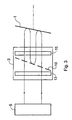
- Fig. 1 shows an apparatus according to a first embodiment of the invention;
- Fig. 2 shows in detail a rotating unit according to an embodiment of the invention;
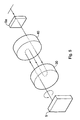
- Fig. 3 shows the path of the beam through the apparatus shown in Fig. 1 and Fig.2;
- Fig. 4 shows an apparatus according to a further embodiment of the invention;
- Fig. 5 shows an apparatus according to an embodiment of the invention arranged in transmission.
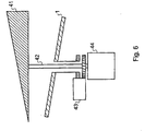
- Fig. 6 shows an apparatus according to a further embodiment of the invention;
- Fig. 7 shows the wedge of Fig. 6 in detail.
-
- Referring first to Fig. 1 a rotating mirror 1 is inclined at around 11° and a
rotating unit 3, (shown in more detail in Fig. 2) which includes a linear polariser inclined at an angle of around 22°. A fixedquarter wave plate 5 is located in front of therotating unit 3 to convert a linearly polarised beam to a circularly polarised beam. - Fig. 2 shows the
rotating unit 3 in detail. This comprises an inclinedlinear polariser 10 positioned between twoquarter wave plates - A linearly polarised beam is converted by the fixed
quarter wave plate 5 to a right circularly polarised beam In this embodiment, the incident beam is horizontally polarised and the fixedquarter wave plate 5, which has a fast axis at +45° produces right-handed circularly polarised beam. Though other directions are possible, for example, left circularly polarised beam may alternatively be used). - Referring to Fig.3, the right circularly polarised beam passes through the first
quarter wave plate 13 ofrotating unit 3 which converts the beam to linear polarised. The beam then passes through thepolariser 10 and through the secondquarter wave plate 15 of the rotating unit, where it is converted to circular polarised light. The beam then reaches the rotating mirror 1, which rotates in the opposite direction from rotatingunit 3 but at the same speed, and the beam is reflected from the counter-rotating mirror 1. - The beam then passes back to the rotating
unit 3 where it passes through thequarter wave plate 15. This time the light is reflected at theinclined polariser 10, because the plane of polarisation has been rotated through 90° when reflected at the rotating mirror 1 and transmitted by thequarter wave plate 15. The beam then passes to the counter rotating mirror 1 where it is reflected again, the handedness of the circularly polarised radiation undergoing a further change, and passes back through therotating unit 3, this time passing through thelinear polariser 10. - In isolation, the
rotating unit 3 and the counter rotating mirror 1 produce conical scans, but in this tandem arrangement, with the rotations at the same speed and in opposite directions. Parts of the conical scans are effectively cancelled out to produce a linear scan. This cancellation is virtually complete if the inclination of theinclined polariser 10 is twice that of the counter-rotating mirror 1. - Fig. 4 shows an alternative embodiment in which the rotating
unit 20 consists of aquarter wave 23 plate and alinear polariser 21. The apparatus also has aFaraday rotator 25, which rotates the plane of polarization by 45°. - In the embodiment shown in Fig.4, the fixed
quarter wave plate 5 converts a linearly polarised beam in to a circularly polarised beam. This circularly polarised beam is received by the rotatingunit 20 and is converted into a linear beam by thequarter wave plate 23. The beam then passes through thelinear polariser 21 and is then received by theFaraday rotator 25 which rotates the plane of the polarisation of the incident beam by 45°. This beam is then incident at the rotating mirror 1 where it is reflected. - The beam passes back through the
Faraday rotator 25 where it undergoes a further rotation of 45° in its plane of polarisation. - The beam is now polarised at right angles to the transmission axis of the
inclined polariser 21 of therotation unit 3. Thepolariser 21 therefore reflects the incident beam in a conical scan pattern. This reflected beam now passes through theFaraday rotator 25 again and the plane of polarisation is rotated through 45°. The beam is then reflected at the mirror 1, and passes through the Faraday rotator, the plane of polarisation being rotated through 45° so that the beam is then able to pass through theinclined polariser 21 and then through thequarter wave plate 23 of the rotatingunit 20. - In this way, there are two reflections at the rotating mirror 1 and one at the
inclined polariser 21, which is positioned at twice the angle of the rotating mirror 1. - It is also possible for two rotating units similar to that described in Fig. 1 to be used in series. This arrangement is shown in Fig. 5. The
second unit 30 rotates about its axis with the same speed, but in the opposite direction from thefirst unit 40, and has a Faraday rotator between the quarter wave plate and the polariser. In this embodiment, it is not necessary to have a rotating mirror, because the polariser in the secondrotating unit 40 can act as a mirror. The beam passes through the firstrotating unit 30 as described for the first embodiment. The beam then passes to the secondrotating unit 40 and is reflected from the inclined polariser of the second unit. - The reflection at the inclined polariser of the second unit rotates the polarisation of the beam through 90°, so that when the beam passes back to the first polarising unit, it is reflected by the inclined polariser (and the polarisation is rotated through 90°). This time when the beam reaches the second
rotating unit 40 it passes through the inclined polariser and via a secondquarter wave plate 5a which is fixed. - In an alternative embodiment shown in Fig. 6, the rotating unit is a
rotating wedge 41 which rotates in the opposite direction from, and at the same speed as, the rotating mirror 1. The rotating wedge 1 is mounted on adrive shaft 42, and a gear box 43 and amotor 44 are used to control the speed and direction. The rotation is further balanced bybalance weights - Fig. 7 shows the wedge of this embodiment in more detail. The
wedge 41 has asulphur layer 46 sandwiched between twosilica plates - At microwave frequencies sulphur has a refractive index of 1.89 which is close to that of silica (1.94).
- The silica plates are angled to produce a wedge which will deviate a beam through an angle given by:
- The anti-reflective layer should have a refractive index which is the square root of the refractive index of the silica and have an optical thickness of λ/4 where λ is the wavelength of the radiation. PTFE is therefore an appropriate material for the anti-reflective layer, as it has a refractive index of 1.44 which approximates to the square root of the refractive index of silica (1.89). Its thickness should be 1.39 mm for radiation having a wavelength of 8mm (i.e. 35GHz). Alternative materials and thicknesses can be selected by the person skilled in the art. For example, it may be possible to achieve a suitably refractive wedge using a body of silica material, thus omitting the sulphur.
- A beam incident on the arrangement of Figs. 6 and 7 passes twice through the
wedge 46 as it is reflected by the rotating mirror 1.
Claims (19)
- A linear scanning apparatus comprising an optical system having first (10, 30) and second (1, 40) rotatable bodies arranged to rotate at the same speed, in opposite directions, having generally parallel axes of rotation and being inclined to those axes of rotation, the optical system being arranged to define an optical path for a polarised beam so as to form a linear scan, wherein at least a first one of the bodies is a polariser and the optical system is arranged such that the optical path passes through the polariser, is reflected at the second body back to the polariser, and is reflected by the polariser back to the second body.
- A scanning apparatus according to claim 1 wherein the axes of rotation of the first and second rotatable bodies are coincident.
- A scanning apparatus according to claim 1 or claim 2 wherein the second rotatable body is a reflective member and the optical path is arranged such that once the polarised beam is reflected back from the polariser to the second body, the second body reflects the beam back to the polariser and the beam passes through the polariser.
- A scanning apparatus according to claim 1 or claim 2 wherein the second rotatable body is a polariser and the optical path is arranged such that once the polarised beam is reflected back to the second body it is transmitted through the second body.
- A scanning apparatus according to any one of the above claims wherein the angle of inclination of the first body is twice the angle of inclination of the second body.
- A scanning apparatus according to any one of the above claims wherein the first body is a linear polariser.
- A scanning apparatus according to claim 6 wherein first and second quarter wave plates are provided, one on each side of the first body, and wherein the apparatus has means for rotating the first and second quarter wave plates about the same axis as the first body, at the same speed and in the same direction.
- A scanning apparatus according to claim 7 wherein the second body is a linear polariser, wherein there are third and fourth quarter wave plates, one on each side of the second body, the third and fourth quarter wave plates being arranged to rotate about the same axis as the second body, at the same speed and in the same direction as the second body, and wherein a Faraday rotator is located between the second body and the third quarter wave plate which is located on the first body side of the second body.
- A scanning apparatus according to claim 6 wherein a quarter wave plate is located on one side of the first body and is arranged to rotate about the same axis as the first body, at the same speed and in the same direction as the first body, and a Faraday rotator is located on the other side of the first body.
- A scanning apparatus according to claim 7 or claim 8 wherein the quarter wave plate(s) and the first body are connected to form a rotating unit.
- A scanning apparatus according to any one of the above claims wherein the apparatus further comprises a fixed quarter wave plate for converting linear polarised radiation into circular polarised radiation before it is received by the first body.
- A linear scanning apparatus having a rotatable reflector (1) and a rotatable optical wedge (42) including refractive materials, wherein the wedge (42) and the reflector (1) are arranged to counter-rotate about generally parallel axes, the reflector (1) and the two faces of the wedge (42) being inclined to their respective axes of rotation, such that in use a beam passes through the wedge (42), is reflected by the reflector and passes back through the wedge to provide a linear scan.
- A scanning apparatus according to claim 11 wherein the axes of rotation of the wedge and the reflector are coincident.
- A scanning apparatus according to claim 11 or claim 12 wherein the median plane of the wedge is generally perpendicular to the axis of the wedge's rotation.
- A scanning apparatus according to any one of claims 11-13 wherein the wedge comprises refractive plates supported on a refractive core.
- A method of producing a linear scan, comprising the steps of rotating first and second bodies about generally parallel axes of rotation, at the same speed, but in opposite directions to each other, the first body being a polariser and both the first and second bodies being inclined to their respective axes of rotation, and directing a polarised beam through the first body, so that it is reflected at the second body back to the first body, and is reflected by the first body back to the second body.
- A method according to claim 16 wherein the second body is a reflective member and wherein after the polarised beam is reflected back from the first body to the second body, the second body reflects the beam back to the first body and the beam passes through the first body.
- A method according to claim 16 wherein the second body is a polariser and wherein after the polarised beam is reflected back from the first body to the second body it is transmitted through the second body.
- A method of producing a linear scan including the steps of rotating a reflector and an optical wedge in opposite directions to each other, but around generally parallel axes of rotation, the reflector and the two faces of the optical wedge being inclined to the reflector's axis of rotation and the wedge's respective axis of rotation respectively, and directing a beam so that it passes through the optical wedge, is reflected by the reflector back to the optical wedge and passes through the optical wedge to provide a linear scan.
Applications Claiming Priority (3)
| Application Number | Priority Date | Filing Date | Title |
|---|---|---|---|
| GB0117750 | 2001-07-20 | ||
| GBGB0117750.0A GB0117750D0 (en) | 2001-07-20 | 2001-07-20 | Scanning apparatus |
| PCT/GB2002/003349 WO2003009048A1 (en) | 2001-07-20 | 2002-07-22 | Scanning apparatus |
Publications (2)
| Publication Number | Publication Date |
|---|---|
| EP1410093A1 EP1410093A1 (en) | 2004-04-21 |
| EP1410093B1 true EP1410093B1 (en) | 2004-12-15 |
Family
ID=9918899
Family Applications (1)
| Application Number | Title | Priority Date | Filing Date |
|---|---|---|---|
| EP02745666A Expired - Lifetime EP1410093B1 (en) | 2001-07-20 | 2002-07-22 | Scanning apparatus |
Country Status (9)
| Country | Link |
|---|---|
| US (2) | US7038821B2 (en) |
| EP (1) | EP1410093B1 (en) |
| JP (1) | JP4170901B2 (en) |
| AT (1) | ATE285082T1 (en) |
| CA (2) | CA2689280C (en) |
| DE (1) | DE60202297T2 (en) |
| ES (1) | ES2233837T3 (en) |
| GB (1) | GB0117750D0 (en) |
| WO (1) | WO2003009048A1 (en) |
Families Citing this family (11)
| Publication number | Priority date | Publication date | Assignee | Title |
|---|---|---|---|---|
| US7142340B2 (en) | 2003-10-31 | 2006-11-28 | Hewlett-Packard Development Company, L.P. | Optical scanner apparatuses and optical scanning methods |
| WO2005096064A2 (en) * | 2004-03-30 | 2005-10-13 | Farran Technology Limited | Scanning apparatus |
| US20070195271A1 (en) * | 2004-03-31 | 2007-08-23 | Koninklijke Philips Electronics, N.V. | Projection system with scanning device |
| US7719773B2 (en) * | 2007-11-12 | 2010-05-18 | Ricoh Company, Ltd. | Zoom lens unit and imaging apparatus |
| WO2009126546A1 (en) * | 2008-04-07 | 2009-10-15 | University Of Florida Research Foundation, Inc. | High-precision monolithic optical assemblies and methods for fabrication and alignment thereof |
| US20110040605A1 (en) * | 2009-08-17 | 2011-02-17 | Geoffrey Prentix Evertz | Electronic voting system |
| ES2387484B1 (en) | 2009-10-15 | 2013-08-02 | Alfa Imaging S.A. | SWEEP MULTIESPECTRAL SYSTEM. |
| US20200081129A1 (en) * | 2018-09-10 | 2020-03-12 | Veoneer Us, Inc. | Detection system for a vehicle |
| US12228653B2 (en) | 2022-10-07 | 2025-02-18 | Magna Electronics, Llc | Integrating a sensing system into headlight optics |
| US12092278B2 (en) | 2022-10-07 | 2024-09-17 | Magna Electronics, Llc | Generating a spotlight |
| US12202396B1 (en) | 2023-12-19 | 2025-01-21 | Magna Electronics, Llc | Line-scan-gated imaging for LiDAR headlight |
Family Cites Families (8)
| Publication number | Priority date | Publication date | Assignee | Title |
|---|---|---|---|---|
| DE1282675B (en) * | 1967-03-21 | 1968-11-14 | Eltro G M B H & Co Ges Fuer St | Device for the sinusoidal deflection of a bundle of rays by means of a mirror |
| US3881802A (en) * | 1974-04-18 | 1975-05-06 | Bendix Corp | Wedge-prism optical scanner |
| US4042933A (en) * | 1976-03-19 | 1977-08-16 | The United States Of America As Represented By The Secretary Of The Navy | Antenna line scan system for helicopter wire detection |
| US4168126A (en) * | 1977-07-05 | 1979-09-18 | Altman Associates, Inc. | Electro-optical measuring system using precision light translator |
| US4544228A (en) * | 1982-09-14 | 1985-10-01 | Spectra-Physics, Inc. | Scanning method using a rotating prism |
| US4871904A (en) * | 1987-12-28 | 1989-10-03 | Symbol Technologies, Inc. | Multidirectional optical scanner |
| EP0633541A1 (en) * | 1993-07-06 | 1995-01-11 | Opticon Sensors Europe B.V. | Scanning device |
| GB9707654D0 (en) * | 1997-04-16 | 1997-06-04 | Secr Defence | Scanning apparatus |
-
2001
- 2001-07-20 GB GBGB0117750.0A patent/GB0117750D0/en not_active Ceased
-
2002
- 2002-07-22 WO PCT/GB2002/003349 patent/WO2003009048A1/en not_active Ceased
- 2002-07-22 US US10/484,173 patent/US7038821B2/en not_active Expired - Fee Related
- 2002-07-22 ES ES02745666T patent/ES2233837T3/en not_active Expired - Lifetime
- 2002-07-22 JP JP2003514327A patent/JP4170901B2/en not_active Expired - Fee Related
- 2002-07-22 EP EP02745666A patent/EP1410093B1/en not_active Expired - Lifetime
- 2002-07-22 CA CA2689280A patent/CA2689280C/en not_active Expired - Fee Related
- 2002-07-22 AT AT02745666T patent/ATE285082T1/en not_active IP Right Cessation
- 2002-07-22 DE DE60202297T patent/DE60202297T2/en not_active Expired - Lifetime
- 2002-07-22 CA CA2454194A patent/CA2454194C/en not_active Expired - Fee Related
-
2006
- 2006-03-06 US US11/367,554 patent/US7106482B2/en not_active Expired - Fee Related
Also Published As
| Publication number | Publication date |
|---|---|
| ES2233837T3 (en) | 2005-06-16 |
| US7106482B2 (en) | 2006-09-12 |
| CA2454194A1 (en) | 2003-01-30 |
| CA2454194C (en) | 2010-12-07 |
| DE60202297D1 (en) | 2005-01-20 |
| EP1410093A1 (en) | 2004-04-21 |
| GB0117750D0 (en) | 2001-09-12 |
| US20060146387A1 (en) | 2006-07-06 |
| US20040240019A1 (en) | 2004-12-02 |
| WO2003009048A1 (en) | 2003-01-30 |
| JP4170901B2 (en) | 2008-10-22 |
| US7038821B2 (en) | 2006-05-02 |
| ATE285082T1 (en) | 2005-01-15 |
| DE60202297T2 (en) | 2005-12-15 |
| JP2004536342A (en) | 2004-12-02 |
| CA2689280A1 (en) | 2003-01-30 |
| CA2689280C (en) | 2011-07-12 |
Similar Documents
| Publication | Publication Date | Title |
|---|---|---|
| JP3367940B2 (en) | Laser radar system with phased array beam pointing device | |
| CA1313914C (en) | Optical collimating apparatus | |
| US5253033A (en) | Laser radar system with phased-array beam steerer | |
| CA1302138C (en) | Optical image rotators | |
| US5223956A (en) | Optical beam scanners for imaging applications | |
| CA2454194C (en) | Scanning apparatus | |
| JPS596519B2 (en) | laser gyroscope | |
| JPH027022A (en) | Liquid crystal cell window | |
| US5481384A (en) | Deflector system which produces dual, oppositely directed scanning beams simultaneously or successively | |
| US12510756B2 (en) | Optical apparatus and near-eye display device | |
| US4565426A (en) | Beam splitter | |
| CN114236855A (en) | Optical system and AR apparatus | |
| EP0604031B1 (en) | Optical scanning system | |
| US4850041A (en) | Laser radar with adjustable local oscillator | |
| US7349157B2 (en) | Optical splitting device and optical communication terminal comprising such a device | |
| US4504123A (en) | High efficiency polarizing beamsplitter | |
| US3703330A (en) | Optical rotary joint | |
| US7110623B1 (en) | Temporally coherent depolarizer and a polarization transformer | |
| US4477152A (en) | Reduction of signal modulation caused by polarization in visible optical scanning systems | |
| US12111557B1 (en) | Diffractive beam steering system with high efficiency | |
| JP2647488B2 (en) | Polarization coupler | |
| SU945641A1 (en) | Multi-beam interferometer for spectral and polarization measurements | |
| RU2160914C2 (en) | Device for rotation of the plane of polarization of laser radiation | |
| Kotov | Acousto-optic modulation of multicomponent Ar laser radiation | |
| CN118920259A (en) | Multimode laser |
Legal Events
| Date | Code | Title | Description |
|---|---|---|---|
| PUAI | Public reference made under article 153(3) epc to a published international application that has entered the european phase |
Free format text: ORIGINAL CODE: 0009012 |
|
| 17P | Request for examination filed |
Effective date: 20040216 |
|
| AK | Designated contracting states |
Kind code of ref document: A1 Designated state(s): AT BE BG CH CY CZ DE DK EE ES FI FR GB GR IE IT LI LU MC NL PT SE SK TR |
|
| AX | Request for extension of the european patent |
Extension state: AL LT LV MK RO SI |
|
| GRAP | Despatch of communication of intention to grant a patent |
Free format text: ORIGINAL CODE: EPIDOSNIGR1 |
|
| GRAS | Grant fee paid |
Free format text: ORIGINAL CODE: EPIDOSNIGR3 |
|
| GRAA | (expected) grant |
Free format text: ORIGINAL CODE: 0009210 |
|
| AK | Designated contracting states |
Kind code of ref document: B1 Designated state(s): AT BE BG CH CY CZ DE DK EE ES FI FR GB GR IE IT LI LU MC NL PT SE SK TR |
|
| PG25 | Lapsed in a contracting state [announced via postgrant information from national office to epo] |
Ref country code: TR Free format text: LAPSE BECAUSE OF FAILURE TO SUBMIT A TRANSLATION OF THE DESCRIPTION OR TO PAY THE FEE WITHIN THE PRESCRIBED TIME-LIMIT Effective date: 20041215 Ref country code: CZ Free format text: LAPSE BECAUSE OF FAILURE TO SUBMIT A TRANSLATION OF THE DESCRIPTION OR TO PAY THE FEE WITHIN THE PRESCRIBED TIME-LIMIT Effective date: 20041215 Ref country code: BG Free format text: LAPSE BECAUSE OF FAILURE TO SUBMIT A TRANSLATION OF THE DESCRIPTION OR TO PAY THE FEE WITHIN THE PRESCRIBED TIME-LIMIT Effective date: 20041215 Ref country code: AT Free format text: LAPSE BECAUSE OF FAILURE TO SUBMIT A TRANSLATION OF THE DESCRIPTION OR TO PAY THE FEE WITHIN THE PRESCRIBED TIME-LIMIT Effective date: 20041215 Ref country code: EE Free format text: LAPSE BECAUSE OF FAILURE TO SUBMIT A TRANSLATION OF THE DESCRIPTION OR TO PAY THE FEE WITHIN THE PRESCRIBED TIME-LIMIT Effective date: 20041215 Ref country code: SK Free format text: LAPSE BECAUSE OF FAILURE TO SUBMIT A TRANSLATION OF THE DESCRIPTION OR TO PAY THE FEE WITHIN THE PRESCRIBED TIME-LIMIT Effective date: 20041215 Ref country code: FI Free format text: LAPSE BECAUSE OF FAILURE TO SUBMIT A TRANSLATION OF THE DESCRIPTION OR TO PAY THE FEE WITHIN THE PRESCRIBED TIME-LIMIT Effective date: 20041215 |
|
| REG | Reference to a national code |
Ref country code: GB Ref legal event code: FG4D Ref country code: CH Ref legal event code: EP |
|
| REG | Reference to a national code |
Ref country code: IE Ref legal event code: FG4D |
|
| REF | Corresponds to: |
Ref document number: 60202297 Country of ref document: DE Date of ref document: 20050120 Kind code of ref document: P |
|
| PG25 | Lapsed in a contracting state [announced via postgrant information from national office to epo] |
Ref country code: DK Free format text: LAPSE BECAUSE OF FAILURE TO SUBMIT A TRANSLATION OF THE DESCRIPTION OR TO PAY THE FEE WITHIN THE PRESCRIBED TIME-LIMIT Effective date: 20050315 Ref country code: GR Free format text: LAPSE BECAUSE OF FAILURE TO SUBMIT A TRANSLATION OF THE DESCRIPTION OR TO PAY THE FEE WITHIN THE PRESCRIBED TIME-LIMIT Effective date: 20050315 Ref country code: SE Free format text: LAPSE BECAUSE OF FAILURE TO SUBMIT A TRANSLATION OF THE DESCRIPTION OR TO PAY THE FEE WITHIN THE PRESCRIBED TIME-LIMIT Effective date: 20050315 |
|
| REG | Reference to a national code |
Ref country code: ES Ref legal event code: FG2A Ref document number: 2233837 Country of ref document: ES Kind code of ref document: T3 |
|
| PG25 | Lapsed in a contracting state [announced via postgrant information from national office to epo] |
Ref country code: CY Free format text: LAPSE BECAUSE OF FAILURE TO SUBMIT A TRANSLATION OF THE DESCRIPTION OR TO PAY THE FEE WITHIN THE PRESCRIBED TIME-LIMIT Effective date: 20050722 |
|
| PG25 | Lapsed in a contracting state [announced via postgrant information from national office to epo] |
Ref country code: MC Free format text: LAPSE BECAUSE OF NON-PAYMENT OF DUE FEES Effective date: 20050731 |
|
| PLBE | No opposition filed within time limit |
Free format text: ORIGINAL CODE: 0009261 |
|
| STAA | Information on the status of an ep patent application or granted ep patent |
Free format text: STATUS: NO OPPOSITION FILED WITHIN TIME LIMIT |
|
| ET | Fr: translation filed | ||
| 26N | No opposition filed |
Effective date: 20050916 |
|
| REG | Reference to a national code |
Ref country code: GB Ref legal event code: 732E |
|
| REG | Reference to a national code |
Ref country code: CH Ref legal event code: PUE Owner name: GESTIOEN AVANZADA DE TECNOLOG?AS ELETROENICAS, GA Free format text: THE UNIVERSITY OF READING#PALMER BUILDING, WHITEKNIGHTS#READING RG6 6AY (GB) -TRANSFER TO- GESTIOEN AVANZADA DE TECNOLOG?AS ELETROENICAS, GATE S.A.#C/ GENERAL PARDINAS, 91#28006 MADRID (ES) |
|
| NLS | Nl: assignments of ep-patents |
Owner name: GESTIOEN AVANZADA DE TECNOLOG?AS ELECTROENICAS, GA Effective date: 20061025 |
|
| REG | Reference to a national code |
Ref country code: ES Ref legal event code: PC2A |
|
| BECA | Be: change of holder's address |
Owner name: *GESTION AVANZADA DE TECHNOLOGIAS ELECTRONICAS GAT Effective date: 20061025 |
|
| PG25 | Lapsed in a contracting state [announced via postgrant information from national office to epo] |
Ref country code: PT Free format text: LAPSE BECAUSE OF NON-PAYMENT OF DUE FEES Effective date: 20050515 |
|
| REG | Reference to a national code |
Ref country code: FR Ref legal event code: PLFP Year of fee payment: 14 |
|
| PGFP | Annual fee paid to national office [announced via postgrant information from national office to epo] |
Ref country code: LU Payment date: 20150728 Year of fee payment: 14 |
|
| PGFP | Annual fee paid to national office [announced via postgrant information from national office to epo] |
Ref country code: NL Payment date: 20150727 Year of fee payment: 14 |
|
| PGFP | Annual fee paid to national office [announced via postgrant information from national office to epo] |
Ref country code: CH Payment date: 20150727 Year of fee payment: 14 Ref country code: ES Payment date: 20150715 Year of fee payment: 14 Ref country code: DE Payment date: 20150727 Year of fee payment: 14 Ref country code: IE Payment date: 20150727 Year of fee payment: 14 Ref country code: GB Payment date: 20150720 Year of fee payment: 14 |
|
| PGFP | Annual fee paid to national office [announced via postgrant information from national office to epo] |
Ref country code: FR Payment date: 20150727 Year of fee payment: 14 Ref country code: BE Payment date: 20150730 Year of fee payment: 14 |
|
| PGFP | Annual fee paid to national office [announced via postgrant information from national office to epo] |
Ref country code: IT Payment date: 20150729 Year of fee payment: 14 |
|
| PG25 | Lapsed in a contracting state [announced via postgrant information from national office to epo] |
Ref country code: BE Free format text: LAPSE BECAUSE OF NON-PAYMENT OF DUE FEES Effective date: 20160731 |
|
| REG | Reference to a national code |
Ref country code: DE Ref legal event code: R119 Ref document number: 60202297 Country of ref document: DE |
|
| REG | Reference to a national code |
Ref country code: CH Ref legal event code: PL |
|
| REG | Reference to a national code |
Ref country code: NL Ref legal event code: MM Effective date: 20160801 |
|
| GBPC | Gb: european patent ceased through non-payment of renewal fee |
Effective date: 20160722 |
|
| PG25 | Lapsed in a contracting state [announced via postgrant information from national office to epo] |
Ref country code: FR Free format text: LAPSE BECAUSE OF NON-PAYMENT OF DUE FEES Effective date: 20160801 Ref country code: LI Free format text: LAPSE BECAUSE OF NON-PAYMENT OF DUE FEES Effective date: 20160731 Ref country code: CH Free format text: LAPSE BECAUSE OF NON-PAYMENT OF DUE FEES Effective date: 20160731 Ref country code: NL Free format text: LAPSE BECAUSE OF NON-PAYMENT OF DUE FEES Effective date: 20160801 Ref country code: DE Free format text: LAPSE BECAUSE OF NON-PAYMENT OF DUE FEES Effective date: 20170201 |
|
| REG | Reference to a national code |
Ref country code: FR Ref legal event code: ST Effective date: 20170331 |
|
| REG | Reference to a national code |
Ref country code: IE Ref legal event code: MM4A |
|
| PG25 | Lapsed in a contracting state [announced via postgrant information from national office to epo] |
Ref country code: GB Free format text: LAPSE BECAUSE OF NON-PAYMENT OF DUE FEES Effective date: 20160722 |
|
| PG25 | Lapsed in a contracting state [announced via postgrant information from national office to epo] |
Ref country code: IE Free format text: LAPSE BECAUSE OF NON-PAYMENT OF DUE FEES Effective date: 20160722 |
|
| PG25 | Lapsed in a contracting state [announced via postgrant information from national office to epo] |
Ref country code: IT Free format text: LAPSE BECAUSE OF NON-PAYMENT OF DUE FEES Effective date: 20160722 Ref country code: LU Free format text: LAPSE BECAUSE OF NON-PAYMENT OF DUE FEES Effective date: 20160722 |
|
| PG25 | Lapsed in a contracting state [announced via postgrant information from national office to epo] |
Ref country code: ES Free format text: LAPSE BECAUSE OF NON-PAYMENT OF DUE FEES Effective date: 20160723 |
|
| REG | Reference to a national code |
Ref country code: ES Ref legal event code: FD2A Effective date: 20181128 |