EP1409365B1 - Autoperforation cartridge for dry powered inhalations - Google Patents
Autoperforation cartridge for dry powered inhalations Download PDFInfo
- Publication number
- EP1409365B1 EP1409365B1 EP02767838A EP02767838A EP1409365B1 EP 1409365 B1 EP1409365 B1 EP 1409365B1 EP 02767838 A EP02767838 A EP 02767838A EP 02767838 A EP02767838 A EP 02767838A EP 1409365 B1 EP1409365 B1 EP 1409365B1
- Authority
- EP
- European Patent Office
- Prior art keywords
- cartridge
- frame
- inhaler
- cartridge according
- rigid
- Prior art date
- Legal status (The legal status is an assumption and is not a legal conclusion. Google has not performed a legal analysis and makes no representation as to the accuracy of the status listed.)
- Expired - Lifetime
Links
- 239000000843 powder Substances 0.000 claims abstract description 28
- 239000000463 material Substances 0.000 claims abstract description 7
- 230000001681 protective effect Effects 0.000 claims description 12
- 239000012907 medicinal substance Substances 0.000 claims description 3
- 239000000546 pharmaceutical excipient Substances 0.000 claims description 3
- 239000000853 adhesive Substances 0.000 claims description 2
- 230000003321 amplification Effects 0.000 claims description 2
- 238000003199 nucleic acid amplification method Methods 0.000 claims description 2
- 230000000452 restraining effect Effects 0.000 claims 1
- 239000004033 plastic Substances 0.000 abstract description 5
- 229920003023 plastic Polymers 0.000 abstract description 5
- 230000007246 mechanism Effects 0.000 abstract description 2
- 238000004519 manufacturing process Methods 0.000 description 9
- GUBGYTABKSRVRQ-QKKXKWKRSA-N Lactose Natural products OC[C@H]1O[C@@H](O[C@H]2[C@H](O)[C@@H](O)C(O)O[C@@H]2CO)[C@H](O)[C@@H](O)[C@H]1O GUBGYTABKSRVRQ-QKKXKWKRSA-N 0.000 description 1
- 239000004677 Nylon Substances 0.000 description 1
- 239000004743 Polypropylene Substances 0.000 description 1
- 230000000712 assembly Effects 0.000 description 1
- 238000000429 assembly Methods 0.000 description 1
- 239000002775 capsule Substances 0.000 description 1
- 230000001627 detrimental effect Effects 0.000 description 1
- 239000003814 drug Substances 0.000 description 1
- 238000001914 filtration Methods 0.000 description 1
- 239000008101 lactose Substances 0.000 description 1
- 239000007769 metal material Substances 0.000 description 1
- 238000012986 modification Methods 0.000 description 1
- 230000004048 modification Effects 0.000 description 1
- 229920001778 nylon Polymers 0.000 description 1
- 238000004806 packaging method and process Methods 0.000 description 1
- 239000002245 particle Substances 0.000 description 1
- 229920000515 polycarbonate Polymers 0.000 description 1
- 239000004417 polycarbonate Substances 0.000 description 1
- -1 polypropylene Polymers 0.000 description 1
- 229920001155 polypropylene Polymers 0.000 description 1
- 230000002787 reinforcement Effects 0.000 description 1
- 239000012780 transparent material Substances 0.000 description 1
- 230000000007 visual effect Effects 0.000 description 1
Images


Classifications
-
- A—HUMAN NECESSITIES
- A61—MEDICAL OR VETERINARY SCIENCE; HYGIENE
- A61M—DEVICES FOR INTRODUCING MEDIA INTO, OR ONTO, THE BODY; DEVICES FOR TRANSDUCING BODY MEDIA OR FOR TAKING MEDIA FROM THE BODY; DEVICES FOR PRODUCING OR ENDING SLEEP OR STUPOR
- A61M15/00—Inhalators
- A61M15/0028—Inhalators using prepacked dosages, one for each application, e.g. capsules to be perforated or broken-up
-
- A—HUMAN NECESSITIES
- A61—MEDICAL OR VETERINARY SCIENCE; HYGIENE
- A61M—DEVICES FOR INTRODUCING MEDIA INTO, OR ONTO, THE BODY; DEVICES FOR TRANSDUCING BODY MEDIA OR FOR TAKING MEDIA FROM THE BODY; DEVICES FOR PRODUCING OR ENDING SLEEP OR STUPOR
- A61M15/00—Inhalators
- A61M15/0028—Inhalators using prepacked dosages, one for each application, e.g. capsules to be perforated or broken-up
- A61M15/003—Inhalators using prepacked dosages, one for each application, e.g. capsules to be perforated or broken-up using capsules, e.g. to be perforated or broken-up
- A61M15/0031—Inhalators using prepacked dosages, one for each application, e.g. capsules to be perforated or broken-up using capsules, e.g. to be perforated or broken-up by bursting or breaking the package, i.e. without cutting or piercing
-
- A—HUMAN NECESSITIES
- A61—MEDICAL OR VETERINARY SCIENCE; HYGIENE
- A61M—DEVICES FOR INTRODUCING MEDIA INTO, OR ONTO, THE BODY; DEVICES FOR TRANSDUCING BODY MEDIA OR FOR TAKING MEDIA FROM THE BODY; DEVICES FOR PRODUCING OR ENDING SLEEP OR STUPOR
- A61M15/00—Inhalators
- A61M15/0028—Inhalators using prepacked dosages, one for each application, e.g. capsules to be perforated or broken-up
- A61M15/003—Inhalators using prepacked dosages, one for each application, e.g. capsules to be perforated or broken-up using capsules, e.g. to be perforated or broken-up
- A61M15/0033—Details of the piercing or cutting means
-
- B—PERFORMING OPERATIONS; TRANSPORTING
- B65—CONVEYING; PACKING; STORING; HANDLING THIN OR FILAMENTARY MATERIAL
- B65D—CONTAINERS FOR STORAGE OR TRANSPORT OF ARTICLES OR MATERIALS, e.g. BAGS, BARRELS, BOTTLES, BOXES, CANS, CARTONS, CRATES, DRUMS, JARS, TANKS, HOPPERS, FORWARDING CONTAINERS; ACCESSORIES, CLOSURES, OR FITTINGS THEREFOR; PACKAGING ELEMENTS; PACKAGES
- B65D75/00—Packages comprising articles or materials partially or wholly enclosed in strips, sheets, blanks, tubes or webs of flexible sheet material, e.g. in folded wrappers
- B65D75/28—Articles or materials wholly enclosed in composite wrappers, i.e. wrappers formed by associating or interconnecting two or more sheets or blanks
- B65D75/30—Articles or materials enclosed between two opposed sheets or blanks having their margins united, e.g. by pressure-sensitive adhesive, crimping, heat-sealing, or welding
- B65D75/32—Articles or materials enclosed between two opposed sheets or blanks having their margins united, e.g. by pressure-sensitive adhesive, crimping, heat-sealing, or welding one or both sheets or blanks being recessed to accommodate contents
- B65D75/36—Articles or materials enclosed between two opposed sheets or blanks having their margins united, e.g. by pressure-sensitive adhesive, crimping, heat-sealing, or welding one or both sheets or blanks being recessed to accommodate contents one sheet or blank being recessed and the other formed of relatively stiff flat sheet material, e.g. blister packages, the recess or recesses being preformed
-
- A—HUMAN NECESSITIES
- A61—MEDICAL OR VETERINARY SCIENCE; HYGIENE
- A61M—DEVICES FOR INTRODUCING MEDIA INTO, OR ONTO, THE BODY; DEVICES FOR TRANSDUCING BODY MEDIA OR FOR TAKING MEDIA FROM THE BODY; DEVICES FOR PRODUCING OR ENDING SLEEP OR STUPOR
- A61M2202/00—Special media to be introduced, removed or treated
- A61M2202/06—Solids
- A61M2202/064—Powder
Definitions
- the present invention relates to the technical field of the manufacturing of cartridges for dry powdered inhalations for medicinal use.
- the most efficient inhalers are provided with different items to be assembled (delivering body, spike, spring, grid, housing for the selected cartridge) with consequent costs for manufacturing and arranging the machinery for the assembly line that produces the finished product.
- EP 0 850 082 discloses a cartridge for dry powdered inhalations for medicinal use consisting of a protective concave shell provided with an opening closed by a tearable film, i.e. a press-through packaging or "blister", and containing a rigid and hollow insert.
- the shell and the film make the powder damp-proof and pollutant-proof, while the insert allows to transfer the pressure exerted on the shell directly to the film so that no pressure is exerted on the powder contained in the cartridge. In this way, the powder remains finely dispersed and completely suitable for inhalation by the user.
- Such a cartridge is defined as “autoperforating” cartridge in that it does not require cartridge-opening means (e.g. spike) but only pressure-exerting means.
- cartridge-opening means e.g. spike
- the present invention relates to an autoperforating cartridge that overcomes the above-mentioned drawbacks by means of a rigid frame, located inside the shell, that is an integral part of the rigid base structure of the cartridge itself.
- the frame is a shaped structure that is pivoted through a joint on the rigid base of the cartridge and is manufactured therewith.
- the frame Upon application of a pressure on the shell, the frame leans and takes position in the passage of the inhaler, yet is still connected to the structure of the cartridge itself.
- the frame can be made in the shape of an asymmetric structure, but can be also made as a cone-shaped or dome-shaped structure, anyway following the shape of the cartridge where it is to be located.
- a first important advantage of the cartridge according to the present invention is the reduction in manufacturing costs resulting from the fact that the frame is produced together with the cartridge structure, whereby at least two manufacturing steps (insert production and insert introduction) are dispensed with, and the powder load is easier. Also, such a cartridge can be fitted on different inhalers, preferably disposable and monodose but also multidose, that can be much simpler since they do not require advancing and pressure-exerting means, since the latter can even simply be the user's finger. This results in a dramatic reduction in the number of pieces of the inhaler, which in turn means cost reduction for the machinery required for assembling the selected inhaler.
- a second significant advantage stems from the possibility of selecting the position of the joint between the frame and the cartridge base, so that the protective film will be torn starting from an area opposite to the joint area and there will be the possibility of properly orienting the powder drop.
- Still another great advantage results from the permanent connection between the insert and the cartridge base, whereby the frame leans into the inhaler but does not completely and uncontrollably drop down together with the powder so that it does not risk to be an obstacle to the inhalation of the powder by the user.
- it can be provided with a properly mesh-shaped distal portion to act as a grid for the disaggregation of the medicinal powder from the excipient, in case the inhaler is not provided with a suitable grid.
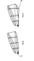
- a cartridge according to the present invention includes a plastic frame 1, in this case asymmetrically shaped with a trapezoidal longitudinal section, placed inside an equally-shaped shell 2 that receives and protects the medicinal powder 3, the bottom of the cartridge being closed by a protective film 4.
- the novel aspect of the present invention consists in a flexible joint 5 that permanently connects frame 1 to the rigid cartridge base 6.
- a connection can be achieved through different types of joint, in particular a "butterfly" snap-joint (shown in the boxed enlargement of joint 5) that through a raised bridge with lateral recesses provides an amplification of the push on the frame and prevents the reverse movement of the latter.
- fig.2a shows a joint 7consisting of a simple flexible strip.
- frame 1 can also be suitably shaped to make the piercing operation easier.
- frame 1 can be provided with a distal bottom angle 8 that easily starts a central line of tear.
- the asymmetric shape of frame 1 illustrated in the figures, in which the distal part that in use will be adjacent to the inlet of the inhalation duct has a larger convexity than the proximal part where joint 5 is provided, is designed so that the piercing of film 4 occurs at the distal end of the cartridge. In this way, powder 3 tends to slide along the tearing film 4 and to drop closer to the inhalation duct rather than dropping backward as it could occur with prior art separate piercing inserts.
- shell 2 can be made from a transparent material 9 (fig.3a).
- shell 2 can be made from a semi-opaque material 10 (fig.3b) that provides the required protection while still allowing a visual check of the proper discharge of the powder.
- Fig.3c illustrates how another way to make the cartridge opening easier is to form in the bottom protective film 4 a dashed, as shown in the drawing, or continuous groove 11 that defines a preferential break line. In this way the pressure on the cartridge required to tear film 4 is lower, whereby even weak users such as ill, elderly or very young people can easily carry out the squashing required to drop the powder into the inhaler.
- frame 1 can not be completely expelled from the cartridge thanks to the connection to base 6, nonetheless a reinforced area 12 can be provided along the above-mentioned groove 11 so as to assure the correct orientation in the film tear. Such a reinforcement also guarantees that the torn film is not completely detached from the cartridge, thus risking to drop down with the powder, which would be detrimental to the subsequent inhalation by the user.
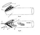
- a cartridge 13 is placed in a simple and essential inhaler consisting of a tubular duct 14 provided with a suitable end lodging seat 15 formed in an oblique portion of the distal part of duct 14.
- the cartridge can be fixed in different ways, such as by an adhesive agent arranged thereon, pressing, embedding, threading or even by placing a lock ring 16. Once the cartridge has been fixed in the inhaler, the user is simply required to press the cartridge so that the internal rigid frame tears open the protective film and allows the powder to drop down into the inhaler from where it can be inhaled by the user.
- Said powder will be subjected to lateral and rear inhalation streams (arrows 21), that enter the inhaler through one or more air intakes 22 and carry the powder toward the proximal duct outlet where it enters the user's mouth.
- the air intakes can also be formed in the rigid cartridge base surrounding the central drug-holding part, so as to obtain other air streams that cooperate in transporting the powder.
- the rigid structure of the cartridge comprising frame 1 and base 6, will be made of a plastic, polypropylene, polycarbonate, nylon or metal material (or any other material suitable for the purpose). Said rigid structure is firstly lined in its convex rear part with a material selected for the blister to form shell 2, then it is filled with the medicinal powder and finally sealed with the protective film 4 on the base part.
- the cage-like structure of frame 1 can be made with a narrow mesh, at least in the distal portion, when a further system of disaggregation of the powder particles in addition to the one usually provided with the inhaler itself is needed.
- the disaggregation of the medicinal substance from the excipient usually lactose is caused by the impact onto the filtering grid and by the strength of the inhalation streams.
Landscapes
- Health & Medical Sciences (AREA)
- Engineering & Computer Science (AREA)
- Bioinformatics & Cheminformatics (AREA)
- Pulmonology (AREA)
- Anesthesiology (AREA)
- Biomedical Technology (AREA)
- Heart & Thoracic Surgery (AREA)
- Hematology (AREA)
- Life Sciences & Earth Sciences (AREA)
- Animal Behavior & Ethology (AREA)
- General Health & Medical Sciences (AREA)
- Public Health (AREA)
- Veterinary Medicine (AREA)
- Chemical & Material Sciences (AREA)
- Composite Materials (AREA)
- Mechanical Engineering (AREA)
- Medicinal Preparation (AREA)
- Medical Preparation Storing Or Oral Administration Devices (AREA)
- Packages (AREA)
- Filtering Of Dispersed Particles In Gases (AREA)
Abstract
Description
Claims (14)
- Cartridge for dry powdered inhalations (3) including a shaped rigid frame (1) placed inside an equally-shaped crushable shell (2) suitable to receive and protect said powder (3), the bottom of the cartridge being closed by a tearable protective film (4) applied to a rigid cartridge base (6), characterized in that said rigid frame (1) is pivoted on said base (6) through a flexible joint (5; 7) that permanently connects the frame (1) to the base (6).
- Cartridge according to claim 1, characterized in that the flexible joint is a "butterfly" snap-joint (5) that provides an amplification of the push on the frame (1) and prevents the reverse movement of the latter.
- Cartridge according to claim 1, characterized in that the flexible joint is a simple flexible strip (7) that does not provide a non-return function.
- Cartridge according to one of the preceding claims, characterized in that the rigid frame (1) is provided with a distal bottom angle (8) suitable to start a central line of tear in the protective film (4).
- Cartridge according to one of the preceding claims, characterized in that the shell (2) is made from a transparent (9) or semi-opaque (10) material suitable to allow the user to check that all the powder (3) actually dropped down from the cartridge.
- Cartridge according to one of the preceding claims, characterized in that the bottom protective film (4) is provided with a dashed or continuous groove (11) that defines a preferential break line.
- Cartridge according to claim 6, characterized in that a reinforced area (12) of the film (4) is provided along the groove (11).
- Cartridge according to one of the preceding claims, characterized in that the frame (1) has an asymmetric shape in which the distal part that in use will be adjacent to the inlet of the inhalation duct of an inhaler has a larger convexity than the proximal part where the joint (5) is provided.
- Cartridge according to one of the preceding claims, characterized in that the rigid base (6) is provided with restraining means suitable to block the cartridge in a corresponding seat of an inhaler, such as an adhesive agent, a thread, a snap-fitting or the like.
- Cartridge according to one of the preceding claims, characterized in that the rigid base (6) is provided with one or more passages suitable to act as air intakes for inhalation streams.
- Cartridge according to one of the preceding claims, characterized in that the structure of the frame (1) is made with a narrow mesh, at least in the distal portion, suitable to act as a grid for the disaggregation of the medicinal substance from the excipient.
- Monodose inhalation system characterized in that it consists of an autoperforating cartridge (13) according to one of the preceding claims and an inhaler with a suitable cartridge-receiving seat (15).
- Monodose inhalation system according to claim 12, characterized in that the cartridge-receiving seat (15) is formed in an oblique portion of the distal part of the inhaler duct (14).
- Monodose inhalation system according to claim 12 or 13, characterized in that it includes a lock ring (16) suitable to lock the cartridge (13) in its seat (15).
Applications Claiming Priority (3)
| Application Number | Priority Date | Filing Date | Title |
|---|---|---|---|
| IT2001PG000036A ITPG20010036A1 (en) | 2001-07-24 | 2001-07-24 | SELF-PERFORATING CARTRIDGE FOR INHALATION DRIED DUST DISPENSERS |
| ITPG20010036 | 2001-07-24 | ||
| PCT/IT2002/000486 WO2003011708A1 (en) | 2001-07-24 | 2002-07-24 | Autoperforation cartridge for dry powered inhalations |
Publications (2)
| Publication Number | Publication Date |
|---|---|
| EP1409365A1 EP1409365A1 (en) | 2004-04-21 |
| EP1409365B1 true EP1409365B1 (en) | 2005-10-19 |
Family
ID=11452764
Family Applications (1)
| Application Number | Title | Priority Date | Filing Date |
|---|---|---|---|
| EP02767838A Expired - Lifetime EP1409365B1 (en) | 2001-07-24 | 2002-07-24 | Autoperforation cartridge for dry powered inhalations |
Country Status (7)
| Country | Link |
|---|---|
| EP (1) | EP1409365B1 (en) |
| AT (1) | ATE307070T1 (en) |
| DE (1) | DE60206766T2 (en) |
| DK (1) | DK1409365T3 (en) |
| ES (1) | ES2250706T3 (en) |
| IT (1) | ITPG20010036A1 (en) |
| WO (1) | WO2003011708A1 (en) |
Cited By (2)
| Publication number | Priority date | Publication date | Assignee | Title |
|---|---|---|---|---|
| CN100522274C (en) * | 2004-09-16 | 2009-08-05 | 詹皮耶罗·科西 | Disposable single dose inhaler for powdered medicaments |
| CN109195652A (en) * | 2016-09-19 | 2019-01-11 | 和利康意大利有限公司 | The disposable single dose inhaler of powder medicaments |
Families Citing this family (7)
| Publication number | Priority date | Publication date | Assignee | Title |
|---|---|---|---|---|
| GB0320171D0 (en) | 2003-08-28 | 2003-10-01 | Optinose As | Delivery devices |
| EP2346554B1 (en) | 2008-09-26 | 2015-09-16 | Oriel Therapeutics, Inc. | Inhaler mechanisms with radially biased piercers and related methods |
| CA2732842C (en) | 2008-09-26 | 2018-01-09 | Oriel Therapeutics, Inc. | Inhalers with airway disks having discrete airway channels and related disks and methods |
| US8381721B2 (en) | 2008-09-26 | 2013-02-26 | Oriel Therapeutics, Inc. | Dry powder inhalers with dual piercing members and related devices and methods |
| US9050427B2 (en) | 2008-09-30 | 2015-06-09 | Oriel Therapeutics, Inc. | Dry powder inhalers with multi-facet surface deagglomeration chambers and related devices and methods |
| WO2010039202A2 (en) | 2008-10-01 | 2010-04-08 | Oriel Therapeutics, Inc. | Dry powder inhalers with rotating piercing mechanisms and related devices and methods |
| USD641076S1 (en) | 2010-03-26 | 2011-07-05 | Oriel Therapeutics, Inc. | Dry powder inhaler |
Family Cites Families (3)
| Publication number | Priority date | Publication date | Assignee | Title |
|---|---|---|---|---|
| GB8314308D0 (en) * | 1983-05-24 | 1983-06-29 | Matburn Holdings Ltd | Medical administration devices |
| FR2738152B1 (en) * | 1995-09-04 | 1998-01-23 | Tebro | POWDER PRODUCT PREDOSING DEVICE FOR A PRODUCT DISPENSER |
| US20010029947A1 (en) * | 1999-12-17 | 2001-10-18 | Steve Paboojian | Receptacles to facilitate the extraction of powders |
-
2001
- 2001-07-24 IT IT2001PG000036A patent/ITPG20010036A1/en unknown
-
2002
- 2002-07-24 EP EP02767838A patent/EP1409365B1/en not_active Expired - Lifetime
- 2002-07-24 AT AT02767838T patent/ATE307070T1/en active
- 2002-07-24 DK DK02767838T patent/DK1409365T3/en active
- 2002-07-24 DE DE60206766T patent/DE60206766T2/en not_active Expired - Lifetime
- 2002-07-24 ES ES02767838T patent/ES2250706T3/en not_active Expired - Lifetime
- 2002-07-24 WO PCT/IT2002/000486 patent/WO2003011708A1/en not_active Ceased
Cited By (3)
| Publication number | Priority date | Publication date | Assignee | Title |
|---|---|---|---|---|
| CN100522274C (en) * | 2004-09-16 | 2009-08-05 | 詹皮耶罗·科西 | Disposable single dose inhaler for powdered medicaments |
| CN109195652A (en) * | 2016-09-19 | 2019-01-11 | 和利康意大利有限公司 | The disposable single dose inhaler of powder medicaments |
| CN109195652B (en) * | 2016-09-19 | 2021-04-06 | 和利康意大利有限公司 | Disposable single dose inhaler for powdered medicaments |
Also Published As
| Publication number | Publication date |
|---|---|
| ES2250706T3 (en) | 2006-04-16 |
| DK1409365T3 (en) | 2006-02-20 |
| WO2003011708A1 (en) | 2003-02-13 |
| DE60206766D1 (en) | 2006-03-02 |
| ATE307070T1 (en) | 2005-11-15 |
| DE60206766T2 (en) | 2006-07-06 |
| EP1409365A1 (en) | 2004-04-21 |
| ITPG20010036A1 (en) | 2003-01-24 |
Similar Documents
| Publication | Publication Date | Title |
|---|---|---|
| KR100390480B1 (en) | inspirator | |
| AU771992B2 (en) | Wearable aerosol delivery apparatus | |
| KR100467058B1 (en) | Inhaler for powdered medicaments | |
| US5797392A (en) | Inhaler | |
| RU2158609C1 (en) | Inhaler for receiving powder drugs from blister packages | |
| US8047203B2 (en) | Unit dose dry powder inhaler | |
| AU2006225241B2 (en) | Medication Holder | |
| CA2969030C (en) | Single-dose powder inhalator and method for the production thereof | |
| LT3718B (en) | Disponsable inhaler | |
| JP2008540264A (en) | Configuration and method for opening a cavity, drug package and distribution device | |
| JP2010512882A (en) | Inhalation device for powdered drugs | |
| EP1675636A1 (en) | Medication holder | |
| JP5394440B2 (en) | Inhaler | |
| ES2250706T3 (en) | SELF-DRILLING CARTRIDGE FOR DRY POWDER INHALATIONS. | |
| EP1177805A1 (en) | Powder inhaler | |
| JP3723442B2 (en) | Mouth-mounted liquid extraction tube | |
| HK30090545A2 (en) | Inhalers as well as protective device and breath indicator | |
| MXPA97005502A (en) | An inhala | |
| MXPA98000024A (en) | Inhaler to administer medicines contained in type ampo packaging |
Legal Events
| Date | Code | Title | Description |
|---|---|---|---|
| PUAI | Public reference made under article 153(3) epc to a published international application that has entered the european phase |
Free format text: ORIGINAL CODE: 0009012 |
|
| 17P | Request for examination filed |
Effective date: 20040219 |
|
| AK | Designated contracting states |
Kind code of ref document: A1 Designated state(s): AT BE BG CH CY CZ DE DK EE ES FI FR GB GR IE IT LI LU MC NL PT SE SK TR |
|
| AX | Request for extension of the european patent |
Extension state: AL LT LV MK RO SI |
|
| 17Q | First examination report despatched |
Effective date: 20040518 |
|
| GRAP | Despatch of communication of intention to grant a patent |
Free format text: ORIGINAL CODE: EPIDOSNIGR1 |
|
| GRAS | Grant fee paid |
Free format text: ORIGINAL CODE: EPIDOSNIGR3 |
|
| GRAA | (expected) grant |
Free format text: ORIGINAL CODE: 0009210 |
|
| AK | Designated contracting states |
Kind code of ref document: B1 Designated state(s): AT BE BG CH CY CZ DE DK EE ES FI FR GB GR IE IT LI LU MC NL PT SE SK TR |
|
| PG25 | Lapsed in a contracting state [announced via postgrant information from national office to epo] |
Ref country code: FI Free format text: LAPSE BECAUSE OF FAILURE TO SUBMIT A TRANSLATION OF THE DESCRIPTION OR TO PAY THE FEE WITHIN THE PRESCRIBED TIME-LIMIT Effective date: 20051019 |
|
| REG | Reference to a national code |
Ref country code: GB Ref legal event code: FG4D |
|
| REG | Reference to a national code |
Ref country code: CH Ref legal event code: EP |
|
| REG | Reference to a national code |
Ref country code: IE Ref legal event code: FG4D |
|
| REG | Reference to a national code |
Ref country code: CH Ref legal event code: NV Representative=s name: RIEDERER HASLER & PARTNER PATENTANWAELTE AG |
|
| PG25 | Lapsed in a contracting state [announced via postgrant information from national office to epo] |
Ref country code: BG Free format text: LAPSE BECAUSE OF FAILURE TO SUBMIT A TRANSLATION OF THE DESCRIPTION OR TO PAY THE FEE WITHIN THE PRESCRIBED TIME-LIMIT Effective date: 20060119 |
|
| REG | Reference to a national code |
Ref country code: SE Ref legal event code: TRGR |
|
| REG | Reference to a national code |
Ref country code: GR Ref legal event code: EP Ref document number: 20050403736 Country of ref document: GR |
|
| REG | Reference to a national code |
Ref country code: DK Ref legal event code: T3 |
|
| REF | Corresponds to: |
Ref document number: 60206766 Country of ref document: DE Date of ref document: 20060302 Kind code of ref document: P |
|
| REG | Reference to a national code |
Ref country code: ES Ref legal event code: FG2A Ref document number: 2250706 Country of ref document: ES Kind code of ref document: T3 |
|
| ET | Fr: translation filed | ||
| PGFP | Annual fee paid to national office [announced via postgrant information from national office to epo] |
Ref country code: IE Payment date: 20060721 Year of fee payment: 5 |
|
| PGFP | Annual fee paid to national office [announced via postgrant information from national office to epo] |
Ref country code: SK Payment date: 20060724 Year of fee payment: 5 |
|
| PG25 | Lapsed in a contracting state [announced via postgrant information from national office to epo] |
Ref country code: MC Free format text: LAPSE BECAUSE OF NON-PAYMENT OF DUE FEES Effective date: 20060731 |
|
| PLBE | No opposition filed within time limit |
Free format text: ORIGINAL CODE: 0009261 |
|
| STAA | Information on the status of an ep patent application or granted ep patent |
Free format text: STATUS: NO OPPOSITION FILED WITHIN TIME LIMIT |
|
| 26N | No opposition filed |
Effective date: 20060720 |
|
| REG | Reference to a national code |
Ref country code: DK Ref legal event code: EBP |
|
| PGFP | Annual fee paid to national office [announced via postgrant information from national office to epo] |
Ref country code: CZ Payment date: 20060724 Year of fee payment: 5 Ref country code: DK Payment date: 20060727 Year of fee payment: 5 |
|
| REG | Reference to a national code |
Ref country code: IE Ref legal event code: MM4A |
|
| PG25 | Lapsed in a contracting state [announced via postgrant information from national office to epo] |
Ref country code: CZ Free format text: LAPSE BECAUSE OF NON-PAYMENT OF DUE FEES Effective date: 20070724 Ref country code: SK Free format text: LAPSE BECAUSE OF NON-PAYMENT OF DUE FEES Effective date: 20070724 |
|
| PG25 | Lapsed in a contracting state [announced via postgrant information from national office to epo] |
Ref country code: EE Free format text: LAPSE BECAUSE OF FAILURE TO SUBMIT A TRANSLATION OF THE DESCRIPTION OR TO PAY THE FEE WITHIN THE PRESCRIBED TIME-LIMIT Effective date: 20051019 |
|
| PG25 | Lapsed in a contracting state [announced via postgrant information from national office to epo] |
Ref country code: LU Free format text: LAPSE BECAUSE OF NON-PAYMENT OF DUE FEES Effective date: 20060724 Ref country code: DK Free format text: LAPSE BECAUSE OF NON-PAYMENT OF DUE FEES Effective date: 20070731 |
|
| PG25 | Lapsed in a contracting state [announced via postgrant information from national office to epo] |
Ref country code: IE Free format text: LAPSE BECAUSE OF NON-PAYMENT OF DUE FEES Effective date: 20070724 |
|
| PG25 | Lapsed in a contracting state [announced via postgrant information from national office to epo] |
Ref country code: CY Free format text: LAPSE BECAUSE OF FAILURE TO SUBMIT A TRANSLATION OF THE DESCRIPTION OR TO PAY THE FEE WITHIN THE PRESCRIBED TIME-LIMIT Effective date: 20051019 |
|
| REG | Reference to a national code |
Ref country code: FR Ref legal event code: PLFP Year of fee payment: 14 |
|
| REG | Reference to a national code |
Ref country code: CH Ref legal event code: PUE Owner name: HOLLYCON ITALY PTE. LTD. - S.R.L., IT Free format text: FORMER OWNER: GIAMPIERO COSSI, IT Ref country code: CH Ref legal event code: PUE Owner name: GIAMPIERO COSSI, IT Free format text: FORMER OWNER: CECCHINI, MARCO, IT Ref country code: PT Ref legal event code: PC4A Owner name: GIAMPIERO COSSI, IT Effective date: 20151023 |
|
| REG | Reference to a national code |
Ref country code: PT Ref legal event code: PC4A Owner name: HOLLYCON ITALY PTE. LTD.- S.R.L., IT Effective date: 20151023 |
|
| REG | Reference to a national code |
Ref country code: DE Ref legal event code: R082 Ref document number: 60206766 Country of ref document: DE Representative=s name: COHAUSZ & FLORACK PATENT- UND RECHTSANWAELTE P, DE Ref country code: DE Ref legal event code: R081 Ref document number: 60206766 Country of ref document: DE Owner name: HOLLYCON ITALY PTE. LTD. - S.R.L., IT Free format text: FORMER OWNERS: CECCHINI, MARCO, PERUGIA, IT; DEVEGLIA, ROBERTA, PERUGIA, IT |
|
| REG | Reference to a national code |
Ref country code: FR Ref legal event code: TP Owner name: HOLLYCON INTALY PTE. LTD. - S.R.L., IT Effective date: 20151224 |
|
| REG | Reference to a national code |
Ref country code: NL Ref legal event code: PD Owner name: HOLLYCON ITALY PTE. LTD. - S.R.L.; IT Free format text: DETAILS ASSIGNMENT: VERANDERING VAN EIGENAAR(S), OVERDRACHT; FORMER OWNER NAME: ROBERTA DEVEGLIA Effective date: 20151102 |
|
| REG | Reference to a national code |
Ref country code: ES Ref legal event code: PC2A Owner name: HOLLYCON ITALY PTE. LTD. S.R.L. Effective date: 20160705 |
|
| REG | Reference to a national code |
Ref country code: FR Ref legal event code: PLFP Year of fee payment: 15 |
|
| REG | Reference to a national code |
Ref country code: AT Ref legal event code: PC Ref document number: 307070 Country of ref document: AT Kind code of ref document: T Owner name: HOLLYCON ITALY PTE. LTD. - S.R.L., IT Effective date: 20160831 |
|
| REG | Reference to a national code |
Ref country code: GB Ref legal event code: 732E Free format text: REGISTERED BETWEEN 20161201 AND 20161207 |
|
| REG | Reference to a national code |
Ref country code: FR Ref legal event code: PLFP Year of fee payment: 16 |
|
| REG | Reference to a national code |
Ref country code: FR Ref legal event code: PLFP Year of fee payment: 17 |
|
| PGFP | Annual fee paid to national office [announced via postgrant information from national office to epo] |
Ref country code: NL Payment date: 20200727 Year of fee payment: 19 |
|
| PGFP | Annual fee paid to national office [announced via postgrant information from national office to epo] |
Ref country code: ES Payment date: 20200922 Year of fee payment: 19 Ref country code: GB Payment date: 20200727 Year of fee payment: 19 Ref country code: FR Payment date: 20200721 Year of fee payment: 19 Ref country code: PT Payment date: 20200717 Year of fee payment: 19 Ref country code: GR Payment date: 20200714 Year of fee payment: 19 Ref country code: DE Payment date: 20200721 Year of fee payment: 19 Ref country code: TR Payment date: 20200723 Year of fee payment: 19 |
|
| PGFP | Annual fee paid to national office [announced via postgrant information from national office to epo] |
Ref country code: BE Payment date: 20200727 Year of fee payment: 19 Ref country code: CH Payment date: 20200721 Year of fee payment: 19 Ref country code: SE Payment date: 20200727 Year of fee payment: 19 Ref country code: AT Payment date: 20200722 Year of fee payment: 19 |
|
| PGFP | Annual fee paid to national office [announced via postgrant information from national office to epo] |
Ref country code: IT Payment date: 20210714 Year of fee payment: 20 |
|
| REG | Reference to a national code |
Ref country code: DE Ref legal event code: R119 Ref document number: 60206766 Country of ref document: DE |
|
| REG | Reference to a national code |
Ref country code: CH Ref legal event code: PL |
|
| REG | Reference to a national code |
Ref country code: NL Ref legal event code: MM Effective date: 20210801 |
|
| REG | Reference to a national code |
Ref country code: AT Ref legal event code: MM01 Ref document number: 307070 Country of ref document: AT Kind code of ref document: T Effective date: 20210724 |
|
| GBPC | Gb: european patent ceased through non-payment of renewal fee |
Effective date: 20210724 |
|
| REG | Reference to a national code |
Ref country code: BE Ref legal event code: MM Effective date: 20210731 |
|
| PG25 | Lapsed in a contracting state [announced via postgrant information from national office to epo] |
Ref country code: LI Free format text: LAPSE BECAUSE OF NON-PAYMENT OF DUE FEES Effective date: 20210731 Ref country code: GB Free format text: LAPSE BECAUSE OF NON-PAYMENT OF DUE FEES Effective date: 20210724 Ref country code: DE Free format text: LAPSE BECAUSE OF NON-PAYMENT OF DUE FEES Effective date: 20220201 Ref country code: CH Free format text: LAPSE BECAUSE OF NON-PAYMENT OF DUE FEES Effective date: 20210731 Ref country code: AT Free format text: LAPSE BECAUSE OF NON-PAYMENT OF DUE FEES Effective date: 20210724 |
|
| PG25 | Lapsed in a contracting state [announced via postgrant information from national office to epo] |
Ref country code: SE Free format text: LAPSE BECAUSE OF NON-PAYMENT OF DUE FEES Effective date: 20210725 Ref country code: PT Free format text: LAPSE BECAUSE OF NON-PAYMENT OF DUE FEES Effective date: 20220124 Ref country code: NL Free format text: LAPSE BECAUSE OF NON-PAYMENT OF DUE FEES Effective date: 20210801 Ref country code: GR Free format text: LAPSE BECAUSE OF NON-PAYMENT OF DUE FEES Effective date: 20220207 Ref country code: FR Free format text: LAPSE BECAUSE OF NON-PAYMENT OF DUE FEES Effective date: 20210731 |
|
| PG25 | Lapsed in a contracting state [announced via postgrant information from national office to epo] |
Ref country code: BE Free format text: LAPSE BECAUSE OF NON-PAYMENT OF DUE FEES Effective date: 20210731 |
|
| REG | Reference to a national code |
Ref country code: ES Ref legal event code: FD2A Effective date: 20220902 |
|
| PG25 | Lapsed in a contracting state [announced via postgrant information from national office to epo] |
Ref country code: PT Free format text: LAPSE BECAUSE OF EXPIRATION OF PROTECTION Effective date: 20220803 Ref country code: ES Free format text: LAPSE BECAUSE OF NON-PAYMENT OF DUE FEES Effective date: 20210725 |
|
| PG25 | Lapsed in a contracting state [announced via postgrant information from national office to epo] |
Ref country code: PT Free format text: LAPSE BECAUSE OF NON-PAYMENT OF DUE FEES Effective date: 20210726 |
|
| PG25 | Lapsed in a contracting state [announced via postgrant information from national office to epo] |
Ref country code: PT Free format text: LAPSE BECAUSE OF NON-PAYMENT OF DUE FEES Effective date: 20210726 |