EP1408830B1 - Instrument and method of reflexological measurement to standardize and classify a new measure unit - Google Patents
Instrument and method of reflexological measurement to standardize and classify a new measure unit Download PDFInfo
- Publication number
- EP1408830B1 EP1408830B1 EP00954900A EP00954900A EP1408830B1 EP 1408830 B1 EP1408830 B1 EP 1408830B1 EP 00954900 A EP00954900 A EP 00954900A EP 00954900 A EP00954900 A EP 00954900A EP 1408830 B1 EP1408830 B1 EP 1408830B1
- Authority
- EP
- European Patent Office
- Prior art keywords
- reflexological
- point
- value
- measurement
- measure
- Prior art date
- Legal status (The legal status is an assumption and is not a legal conclusion. Google has not performed a legal analysis and makes no representation as to the accuracy of the status listed.)
- Expired - Lifetime
Links
- 238000005259 measurement Methods 0.000 title claims abstract description 17
- 238000000034 method Methods 0.000 title claims description 16
- 239000000523 sample Substances 0.000 claims abstract description 12
- 230000003213 activating effect Effects 0.000 claims description 11
- 239000004020 conductor Substances 0.000 claims description 2
- 230000000415 inactivating effect Effects 0.000 claims description 2
- 238000006243 chemical reaction Methods 0.000 abstract description 8
- 230000007170 pathology Effects 0.000 abstract description 6
- 230000026683 transduction Effects 0.000 abstract description 6
- 238000010361 transduction Methods 0.000 abstract description 6
- 239000011159 matrix material Substances 0.000 abstract description 2
- 230000001575 pathological effect Effects 0.000 description 31
- 210000000056 organ Anatomy 0.000 description 11
- 241000950314 Figura Species 0.000 description 8
- 230000008901 benefit Effects 0.000 description 7
- 230000008569 process Effects 0.000 description 5
- 238000003745 diagnosis Methods 0.000 description 4
- 238000005192 partition Methods 0.000 description 4
- 230000000052 comparative effect Effects 0.000 description 3
- 230000001225 therapeutic effect Effects 0.000 description 3
- 230000006978 adaptation Effects 0.000 description 2
- 230000008859 change Effects 0.000 description 2
- 230000002596 correlated effect Effects 0.000 description 2
- 239000000463 material Substances 0.000 description 2
- 230000001404 mediated effect Effects 0.000 description 2
- 230000003252 repetitive effect Effects 0.000 description 2
- 210000004291 uterus Anatomy 0.000 description 2
- 229910000906 Bronze Inorganic materials 0.000 description 1
- 0 C*C1C(C)CCCC1 Chemical compound C*C1C(C)CCCC1 0.000 description 1
- 230000015572 biosynthetic process Effects 0.000 description 1
- 239000010974 bronze Substances 0.000 description 1
- 210000003679 cervix uteri Anatomy 0.000 description 1
- 230000001447 compensatory effect Effects 0.000 description 1
- 238000010276 construction Methods 0.000 description 1
- KUNSUQLRTQLHQQ-UHFFFAOYSA-N copper tin Chemical compound [Cu].[Sn] KUNSUQLRTQLHQQ-UHFFFAOYSA-N 0.000 description 1
- 238000012937 correction Methods 0.000 description 1
- 230000007812 deficiency Effects 0.000 description 1
- 238000002405 diagnostic procedure Methods 0.000 description 1
- 230000009977 dual effect Effects 0.000 description 1
- 210000001198 duodenum Anatomy 0.000 description 1
- 230000000694 effects Effects 0.000 description 1
- 238000005868 electrolysis reaction Methods 0.000 description 1
- 230000005484 gravity Effects 0.000 description 1
- BHEPBYXIRTUNPN-UHFFFAOYSA-N hydridophosphorus(.) (triplet) Chemical compound [PH] BHEPBYXIRTUNPN-UHFFFAOYSA-N 0.000 description 1
- 210000003734 kidney Anatomy 0.000 description 1
- 210000002429 large intestine Anatomy 0.000 description 1
- 210000004185 liver Anatomy 0.000 description 1
- 238000012986 modification Methods 0.000 description 1
- 230000004048 modification Effects 0.000 description 1
- 210000000496 pancreas Anatomy 0.000 description 1
- 210000002307 prostate Anatomy 0.000 description 1
- 238000011160 research Methods 0.000 description 1
- 230000035945 sensitivity Effects 0.000 description 1
- 210000000952 spleen Anatomy 0.000 description 1
- 229910001220 stainless steel Inorganic materials 0.000 description 1
- 239000010935 stainless steel Substances 0.000 description 1
- 210000002784 stomach Anatomy 0.000 description 1
- 238000012360 testing method Methods 0.000 description 1
- 210000000626 ureter Anatomy 0.000 description 1
- 210000003708 urethra Anatomy 0.000 description 1
Images



Classifications
-
- A—HUMAN NECESSITIES
- A61—MEDICAL OR VETERINARY SCIENCE; HYGIENE
- A61H—PHYSICAL THERAPY APPARATUS, e.g. DEVICES FOR LOCATING OR STIMULATING REFLEX POINTS IN THE BODY; ARTIFICIAL RESPIRATION; MASSAGE; BATHING DEVICES FOR SPECIAL THERAPEUTIC OR HYGIENIC PURPOSES OR SPECIFIC PARTS OF THE BODY
- A61H39/00—Devices for locating or stimulating specific reflex points of the body for physical therapy, e.g. acupuncture
- A61H39/02—Devices for locating such points
-
- A—HUMAN NECESSITIES
- A61—MEDICAL OR VETERINARY SCIENCE; HYGIENE
- A61B—DIAGNOSIS; SURGERY; IDENTIFICATION
- A61B5/00—Measuring for diagnostic purposes; Identification of persons
- A61B5/05—Detecting, measuring or recording for diagnosis by means of electric currents or magnetic fields; Measuring using microwaves or radio waves
-
- A—HUMAN NECESSITIES
- A61—MEDICAL OR VETERINARY SCIENCE; HYGIENE
- A61B—DIAGNOSIS; SURGERY; IDENTIFICATION
- A61B5/00—Measuring for diagnostic purposes; Identification of persons
- A61B5/05—Detecting, measuring or recording for diagnosis by means of electric currents or magnetic fields; Measuring using microwaves or radio waves
- A61B5/053—Measuring electrical impedance or conductance of a portion of the body
- A61B5/0531—Measuring skin impedance
- A61B5/0532—Measuring skin impedance specially adapted for acupuncture or moxibustion
Definitions
- the instrument and the method of reflexological measurement object of the present invention standardizes and classifies a new measure unity for the electromedical sector, suitable to signal, by means of a proper measure/elaboration of electrical conductivity in some points of the auricular pavilion, the diagnose of some pathologies.
- the invention has the purpose to realize:
- circuital solution of the present invention can be called: "VARIABLE RESISTIVE DIVIDERS NET" (see fig.5), it allows remarkable functional advantages, between these ones:
- two divider nets are used, (indicated as Snet-p Snet-n in the scheme), they are constituted by a series of analogical switches in C-Mos connected in parallel with a series of calibrated resistances with a binary scale (in the construction of the prototype the value of 5 K ⁇ has been assigned to Rp).
- This divider enabling opportunely the control of the analogical switches (S WP0 , S WP1 ... S WPn ) may acquire, with a step of 5 K ⁇ , any resistive value comprised between 0 K ⁇ (activating all the controls of the analogical switches) and the sum of all the resistances connected on the resistive net (putting of all the controls of the analogical switches); in our prototype, in which are inserted 8 analogical switches, the device could therefore operate giving to the circuit a divider resistance programmable between 0 K ⁇ and 1.275 M ⁇ .
- An operative logic is actuated, in which, in a first phase, the control of the analogical switches S NET-P searches for a R NET-P , that is as near as possible to the R EAR .
- This new invention moves different reflexological data in a new standard/unity of measure, called FTDB (Ferraro/Tkachenko Data-Base) whose undoubted advantage is that to supply as expression of the diagnostic datum, a value that, independently from the analyzed organ, gives immediately the pathological state that becomes evident on the patient under examination, through its reflexological analysis.
- FTDB Frerraro/Tkachenko Data-Base
- fig. 1 Referring to fig. 1 with (1) is indicated the ear which undergoes to auricular diagnostic, with (2) transductor: Auricular-point/Electric-Resistance, with (3) Matrix for the conversion in FTDB of all the potentially possible values, with (4) a computer with Body-Scanning program, with (5) the diagnostic result expressed in FTDB.
- Fig. 2 represents a measure probe (6) that with an insulated block (7) carries a contact point (8) that can be moved between a level A (all out) and a level B (all in) in order to realize a calibrated pressure from "A" to "B" of 65 gr. - the magnification of the contact point (8) shows that the contact surface is rounded - the magnification of the contact between contact point (8) and auricular pavilion (9) shows a surface of contact (10) of 1,95 mm 2 .
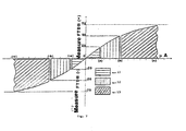
- the limit values (c) and (- d) are obtained using a value double regarding to the maximum experimental measure that has been got in that point; measures that put in evidence even greater lack of balance are put on the same value of the curve FTDB, having already indicated a serious pathological condition.
- the limit values (c) and (- c) are obtained using a value double regarding to the maximum experimental measure that has been got in that point; measures that put in evidence even greater lack of balance are put on the same value of the curve FTDB, having already indicated the maximum pathological condition that the reflexological point under examination allows.
- the limit values (a) and (- b) are obtained using a value double regarding to the maximum experimental measure that has been got in that point; measures that put in evidence even greater lack of balance are put on the same value of the curve FTDB, having already indicated a pathological condition to be defined with a reflexological correlation.
- the present invention allows numerous advantages and to overcome difficulties that could not be won with systems actually in commerce.
Landscapes
- Health & Medical Sciences (AREA)
- Life Sciences & Earth Sciences (AREA)
- General Health & Medical Sciences (AREA)
- Rehabilitation Therapy (AREA)
- Veterinary Medicine (AREA)
- Public Health (AREA)
- Animal Behavior & Ethology (AREA)
- Pathology (AREA)
- Medical Informatics (AREA)
- Pain & Pain Management (AREA)
- Nuclear Medicine, Radiotherapy & Molecular Imaging (AREA)
- Radiology & Medical Imaging (AREA)
- Physics & Mathematics (AREA)
- Biophysics (AREA)
- Epidemiology (AREA)
- Engineering & Computer Science (AREA)
- Biomedical Technology (AREA)
- Heart & Thoracic Surgery (AREA)
- Physical Education & Sports Medicine (AREA)
- Molecular Biology (AREA)
- Surgery (AREA)
- Measurement And Recording Of Electrical Phenomena And Electrical Characteristics Of The Living Body (AREA)
- Analysing Materials By The Use Of Radiation (AREA)
- Paper (AREA)
- Investigation Of Foundation Soil And Reinforcement Of Foundation Soil By Compacting Or Drainage (AREA)
- Spectrometry And Color Measurement (AREA)
- Measurement Of Current Or Voltage (AREA)
- Piezo-Electric Or Mechanical Vibrators, Or Delay Or Filter Circuits (AREA)
- Electrochromic Elements, Electrophoresis, Or Variable Reflection Or Absorption Elements (AREA)
- Investigating Or Analyzing Materials By The Use Of Electric Means (AREA)
- Measuring Pulse, Heart Rate, Blood Pressure Or Blood Flow (AREA)
Abstract
Description
- The instrument and the method of reflexological measurement object of the present invention standardizes and classifies a new measure unity for the electromedical sector, suitable to signal, by means of a proper measure/elaboration of electrical conductivity in some points of the auricular pavilion, the diagnose of some pathologies.
- The invention has the purpose to realize:
- ✔ STANDARDIZATION OF THE MEASURE ACQUISITION PROBE;;
- ✔ ADAPTATION/CALIBRATION OF THE MEASURES, USING A SUITABLE HARDWARE STRUCTURE, IN ORDER TO BE RELATED TO THE SPECIFIC CHARACTERISTICS OF THE PATIENT;
- ✔ ELABORATION/TRANSDUCTION OF THE MEASURES IN ORDER TO OBTAIN A PARAMETER INDICATING THE DIFFERENT PATHOLOGICAL CONDITIONS AND NOT DEPENDING FROM THE SAME REFLEXOLOGICAL SENSITIVITY OF THE ANALYZED ORGANS..
- Hereinafter the innovative methods are illustrated in the single sections in order to obtain this new measure standard that will be called FTDB (Ferraro/Tkachenko Data-Base).
- Many scientific publications describe how the electrical resistance of the human body is modified in the reflexological points, for the reason that it has never been activated a standardization process of the measure, the method has always appeared "not usable/exportable beyond the experience of the single physician, exactly because it is unable to express, in a general way, a parameter that can be repeated and compared; it is in fact known that the electrical resistance on the skin (therefore also on the reflexological points) is modified with the variation of the contact surface between measure organ and epidermic surface changes, or with variation of the pressure by which the measure instrument presses to realize the contact on the skin.
- Our standardization process starts therefore with the structuring of the probe (section that surveys/transduces the value of the electrical resistance of the human body), carrying out to this purpose a series of clinical tests/comparisons in order to obtain the best functional parameters; that is very complex because:
- (a) contact surface should be as wide as possible, without that for this reason the measure is affected/mediated by the resistive value of measures other then the auricular diagnostic point under examination;
- (b) contact surface must be curved, because it must be able to assure a good uniform and repetitive contact between skin and measure probe, without creating to the patient pain conditions (ear is a measure area particularly sensible);
- (c) contact pressure between measure element and reflexological point must be able to assure a good contact between the parts, but in the mean time it must be the less elevate as possible; it could so far squeeze/damage the skin in the contact point and therefore could alter the measure.
At the end of the experimental phase the best parameters were the ones quoted in figure 2. Consequently as standard for FTDB measure unity has been defined a probe that should have the following characteristics: - (d) the point of measure, from now on denominated PTM, must be realized with a conductive material (in our experimental application it has been built with stainless steel) and must have a diameter of 1,5 mm;
- (e) PTM, normally positioned on level-A (see fig.2) must be able to draw back till to reach level-B and in this position it must assure a pressure of 65 grams between PTM and skin (our prototype has been realized with a phosphorous bronze spring that can be suitably calibrated by means of a screw system); user finds very easy to reach level-B because this level coincides with complete drawback of PTM and therefore with the contact on the skin of the insulated material part (see insulated material part fig.2);
- (f) Contact surface that PTM offers to the skin must have a "uniformly lowered spherical" shape whose maximum diameter is equal to 1.5 mm, while the minimum diameter is 0.66 mm; a good compromise that clinical research activated to this purpose has showed able to satisfy the different exigencies that, in this case, are to be mediated: repetitive contact surface in different reflexological points, absence of pain/trouble on the patient. The experimental prototype has been realized by means of an electroerosion process, in order to operate in absolute safety as regards to the qualitative/dimensional aspects of the finished product.
- User, positioning PTM to perform the measure, shall be obviously very careful to position the probe in a perpendicular way to the natural proceeding of the skin on the reflexological point that is to be analyzed; in fact only in this way it is sure that conduction surface (and therefore the value of the measure) is in conformity to the one foreseen in the clinical experimentation phase and that, consequently, the observed data shall report, exactly diagnostic results that reflexological process makes evident on a patient that undergoes to examination.
- Saying first that this description uses two terms nominated point-zero (from now on indicated as PNTZ) and reflexological point of the organ under examination (from now on indicated as PROE), which corresponds to the point AT-83 and to any one of the diagnostic point of measure of the standard Konig-Wancura, it is made evident that the eventual pathological datum that auricular diagnostic system points out it is contained just in the difference of measure (unbalance) existing between the point PNTZ and the point PROE (in some cases the pathological condition is evaluated in an indirect way, that is correlating other reflexological points, without modifying the functional concept of the method.
- To find out these measures actually transduction standards that utilizes a "microAmperometer" system (see fig.3) or a "resistive partition" system (see fig.4), two methodologies of measure that, as we will demonstrate, are little efficacious in this typology of application and undoubtedly, given their low reliability/repetitivity they have considerably slowed down the affirmation of the auricular diagnostic method as "powerful method of diagnosis.
- In the case of measurement by means of "MICRO-AMPEROMETER", in fact, the resistive difference that shows the pathological condition level, is got in a strongly approximate way and with a low level of repetitivity/comparison between patient and patient, in fact, if two patient, that are put in comparison, have different ohmic resistance in point PNTZ, no serious comparison is possible, really the system does not allow reliable comparisons, in different times, not even on the same patient. It has been experimented that PNTZ of the same individuals changes if hours and/or days change.
- To demonstrate the problems that, in such a use, this typology brings, the following association labels/measure parameter are assigned (making reference to fig. 3).
- ✔ "RPTG" indicates the resistance that expresses the pathological condition (difference between the resistance of PNTZ point and the one of PROE point);
- ✔ "IPNTZ" indicates the current that is present on the point PNTZ;
- ✔ "RPNTZ" indicates the resistance that is present on the point PNTZ;
- ✔ "IPROE" indicates the current that is present on the point PROE;
- ✔ "RPROE" indicates the resistance that is present on the point PROE;
- ✔ "VBT1" indicates the tension that is present on the feeding knot;
- ✔ "RL" indicates the resistance that is assigned as current limiter;
- In the case of the measure by means of "RESISTIVE-DIVIDER" (see fig. 4), besides the problems of objective safety for the patient, the method is directed, in fact, to the use of operational amplifier (whose functional standards of tension are rather elevated, typically comprised between +/- 10 and +/- 15 Volts;
- for a potential difference of tension, if something is wrong, comprised between 20 and 30 Volts, the system presents an intrinsic functional non linear conception of its and for this reason it presents a "comparative deficiency" of the provided measures.
- If we want to demonstrate, in this schematic typology the errors that characterize the system we assign, as for preceding case, the following association of labels/parameters of measure:
- "VBT2A/B" indicates the feeding tension (single or dual) on the feeding knot;
- "VPNTZ" indicates the tension of point VINP when it is measured PNTZ;
- "VPROE" indicates the tension of point VINP when it is measured VPROE;
- ✔ "VPTG" indicates the difference between tension VPNTZ and VPROE;
- "RP" indicates the divider resistance used;
- Supposing, in this case, that we want to actuate a comparative diagnosis between two patients that are indicated with suffix A and B , which present respectively a RPNTZ-A of 150 KΩ, and a RPNTZ-B of 350 KΩ, on a RP of 250 KΩ, , in this case we should have in the case "A" a VINP of:


- The circuital solution of the present invention can be called: "VARIABLE RESISTIVE DIVIDERS NET" (see fig.5), it allows remarkable functional advantages, between these ones:
- ✔ an operative tension of absolute safety (it does not require, in spite of the elevated precision, that allows, the use of operational amplifiers);
- ✔ survey of measures structurally without errors;
- ✔ possibility of balancing any effect of electrolysis;
- ✔ possibility of being disposed as easy programmable system of therapeutic rebalancing;
- Hereinafter we describe the characteristics/performances of the circuit, together with the list of the advantages that its structuring allows.
- To characterize its block scheme, two divider nets are used, , (indicated as Snet-p Snet-n in the scheme), they are constituted by a series of analogical switches in C-Mos connected in parallel with a series of calibrated resistances with a binary scale (in the construction of the prototype the value of 5 KΩ has been assigned to Rp).
- This divider, enabling opportunely the control of the analogical switches (SWP0, SWP1 ... SWPn) may acquire, with a step of 5 KΩ, any resistive value comprised between 0 KΩ (activating all the controls of the analogical switches) and the sum of all the resistances connected on the resistive net (putting of all the controls of the analogical switches); in our prototype, in which are inserted 8 analogical switches, the device could therefore operate giving to the circuit a divider resistance programmable between 0 KΩ and 1.275 MΩ.
- A rather important consideration is that both the reading precision and the extension of the maximum resistance, both may be calibrated to the parameter considered the most important, modifying the number of switches and/or the value of the base resistance RP.
- It is important to make evident that the precision of reading of our prototype (8 analogical switch on a base resistance RP of 5 KΩ), is not to be intended as a structure that has a limit precision of 5 KΩ, in fact, if we assign, as in the preceding cases, the labels/parameters associations of measure:
- ✔ "REAR" indicates the resistance on the auricular diagnostic point that is intended to measure;
- ✔ "RNET-P" indicates the resistance on the auricular diagnostic point that is supplied, on the analogical switches, by means of programming, to the net of the positive divider;
- ✔ VBT3" indicates the feeding tension of the circuit;
- ✔ "VADC" indicates the measure tension on the variable resistive divider (measured by the analogical/digital converter and equivalent to VBT3/256 for every digit);
- ✔ "RPRV" indicates the programmed resistance on the variable-resistive-divider;
- ✔ the net of the negative analogical switches (SNET-N), is programmed in such a way that can be totally activated and therefore putting this section with a value of the resistance zero;
- ✔ the net of the polarity switches (SPLRT), is programmed in such a way that only the analogical switches SWC2 e SWC4 are active; in order to make the measure net to became operative as a normal divider positioned on the positive pole;
- An operative logic is actuated, in which, in a first phase, the control of the analogical switches SNET-P searches for a RNET-P, that is as near as possible to the REAR.
- (This condition is reached searching for the value of VADC that is as near as possible to "#128" - if we operate with a net of 8bits) and optimizing the reached result, activating the equation that gets the effective value of REAR, through the under reported formula:

- The formula that from a first analysis seems strongly approximate, it can be really considered valid because: the values RL1 and RL2 are negligible in comparison with the playing quantity, the Buffer-P presents an incoming impedance that, also in this case, is negligible in comparison with the operational parameters as the impedance of short circuits and/or open circuit of analogical switches are.
- Regarding to the functional aspects of the system and evaluating the same under a potential/total profile, it is, at the end, made evident, that:
- 1. the analogical switches of polarity "SPLRT", activating opportunely their control, allow:
- a) to close electrically the reflexological point under examination (in our prototype activating controls: SWC1, SWC2, SWC3, SWC4);
- b) to open electrically the reflexological point under examination (in our prototype inactivating the controls: SWC1, SWC2, SWC3, SWC4);
- c) to polarize in a positive way the reflexological point under examination (in our prototype activating controls: SWC2, SWC4);
- d) to polarize in a negative way the reflexological point under examination (in our prototype activating controls: SWC1, SWC3); and from these possible functional conditions, it is then possible to arrange to activate anti electrolytic, of equalization, therapeutical correction.
- 2. The analogical switches of the resistive divider positioned on the positive polarity "SNET-P", activating opportunely their controls (selectable from SWP0 till SWP7 - as said our prototype has been structured at 8 bits, but could also be at 16 or 32 bits) allow:
- e) To position themselves on different levels of the positive electric potential and therefore to generate specific/particular forms of waves able to compensate in the most suitable way the most right actions necessary to the reflexological points under examination.
- 3. The analogical switches of the resistive divider, positioned on the negative polarity "SNET-N", activating opportunely their controls (selectable from SWN0 till SWN7- as said our prototype has been structured at 8 bits, but could also be at 16 or 32 bits) allow:
- f) To position themselves on different levels of the negative electric potential and therefore to generate specific/particular forms of waves able to compensate in the most suitable way the most right actions necessary to the reflexological points under examination.
- The instrument of the present invention allow a series of advantages as:
- I. BETTER OPERATIVE SAFETY = it can function with a great precision and without the use of operational amplifier and/or high operative tensions; it is adapt to the C-Mos digital standards: +3,3 or +5 Volt d.c.
- II. PERFORMING MEASURES WITH COMPARATIVE TECHNIC = it can perform a comparison between parameters surveyed with the " active divider" positioned both on the positive polarity and on the negative one; All this to the advantage of the quality/reliability of the measure, because it is possible to actuate a double comparison.
- III. SUPPLYING MEASURE PARAMETERS WITHOUT ERRORS DUE TO NON LINEARITY OF THE TRANSDUCTION = it can perform the measurement, both trying in an automatic way the same value of REAR (and using the reading INP-ADC-P/N as level of control to reach the partition VBT3/2), or actuating other forms of partition/reading, in which it is always operative the possibility to change the resistance of partition both on the positive polarity and on the negative one;
- IV. REBALANCING/PRODUCTION OF THERAPEUTICAL EFFECTS = it can perform compensative reflexological forms modifying:
- ✔ Polarities of the current/tension (through analogical switches of SPLRT);
- ✔ impedance of the reflexological point (changing opportunely analogical switches of SPLRT);
- ✔ The "wave forms" generating different levels of electric potential (through analogical switches of SNET-P and of SNET-N).
- Actual methods of auricular diagnostic control, utilizing the value of the delta of measure of any single organ (regarding to zero point) and, to perform the diagnosis, they compare every delta with the different references of pathological state (values are always specific and directed to any particular organ interested); a true confusion of microAmper and/or KΩ where is very difficult to understand.
- This new invention moves different reflexological data in a new standard/unity of measure, called FTDB (Ferraro/Tkachenko Data-Base) whose undoubted advantage is that to supply as expression of the diagnostic datum, a value that, independently from the analyzed organ, gives immediately the pathological state that becomes evident on the patient under examination, through its reflexological analysis.
- To make even more easy its interpretation, this unity of measure has been structured/divided in four operative areas so classified:
- (g) AREA WITH NON PATHOLOGICAL CONDITIONS: where values of the FTDB unity are comprised between 0 and 24 and with polarity both positive and negative;
- (h) AREA WITH LIGHT PATHOLOGICAL CONDITIONS: where values of the FTDB unity are comprised between 25 and 49 with polarity both positive and negative;
- (i) AREA WITH MEDIUM PATHOLOGICAL CONDITIONS: where values of the FTDB unity are comprised between 50 and 74 and with polarity both positive and negative;
- (j) AREA WITH STRONG PATHOLOGICAL CONDITIONS: : where values of the FTDB unity are comprised between 75 and 99 and with polarity negative;
- Furthermore, because the different reflexological points are not indicators of the same pathological gravity and/or of a constant direct interpretation (some people gives pre informations to be correlated with other points). Three different types of curves/matrixes classified in this way have been structured: Curves that expresses areas even with "SERIOUS PATHOLOGICAL CONDITIONS" whose example is given in fig. 6 where the definition parameters have been elaborated for the organs and with the delimitations hereinafter reported (curves are referred to theoretic patients whose zero resistance was re-elaborated at 250KΩ):
- 1. STOMACH (point AT-87) whose principal points of definition are: "a" (equivalent to +25 FTDB) with +2,2 µA; "-a" (equivalent to -25 FTDB) with -2,0 µA; "-c" (equivalent to -75 FTDB) with -6,15 µA.
- 2. LARGE INTESTINE (point AT-91) whose principal points of definition are: "a" (equivalent to +25 FTDB) with +1,6 µA; "-a" (equivalent to -25 FTDB) with -1,3 µA; "-c" (equivalent to -75 FTDB) with -3,15 µA.
- 3. PANCREAS (point AT-96) whose principal points of definition are: "a" (equivalent to +25 FTDB) with +1,2 µA; "-a" (equivalent to -25 FTDB) with -1,0 µA; "-b" (equivalent to -50 FTDB) with -2,8 µA.
- 4. PROSTATE (point AT-93) whose principal points of definition are: "a" (equivalent to +25 FTDB) with +1,8 µA; "-a" (equivalent to -25 FTDB) with -1,5 µA; "-c" (equivalent to -75 FTDB) with -3,8 µA.
- 5. UTERUS CERVIX (point AT-56) whose principal points of definition are: "a" (equivalent to +25 FTDB) with +1,7 µA; "-a" (equivalent to -25 FTDB) con -1,5 µA; "-c" (equivalent to -75 FTDB) with -3,5 µA.
- 6. UTERUS (point AT-58) whose principal points of definition are: "a" (equivalent to +25 FTDB) with +1,8 µA; "-a" (equivalent to -25 FTDB) with -1,5 µA; "-c" (equivalent to -75 FTDB) con 3,8 µA.
- (k) Curves that expresses areas even with "MEDIUM PATHOLOGICAL CONDITIONS", whose example is given in fig. 7 and where the definition parameters have been elaborated for the organs and with the delimitations hereinafter reported (curves are referred to theoretic patients whose zero resistance was re-elaborated at 250KΩ):
- 1. DUODENUM (point AT-88) whose principal points of definition are: "a" (equivant to +25 FTDB) with +1,2 µA; "-a" (equivalent to -25 FTDB) with -1,4 µA.
- 2. BLADDER (point AT-92) whose principal points of definition are: "a" (equivalent to +25 FTDB) with +2,5 µA; "-a" (equivalent to -25 FTDB) with -2,5 µA.
- 3. URETHRA (point AT-94) whose principal points of definition are: "a" (equivalent to +25 FTDB) with +2,0 µA; "-a" (equivalent to -25 FTDB) with -2,0 µA.
- 4. KIDNEY (point AT-95) whose principal points of definition are: "a" (equivalent to +25 FTDB) with +2,5 µA; "-a" (equivalent to -25 FTDB) with -2,3 µA.
- 5. LIVER (point AT-97) whose principal points of definition are: "a" (equivalent to +25 FTDB) with +2,8 µA; "-a" (equivalent to -25 FTDB) with -3,1 µA.
- 6. SPLEEN (point AT-98) whose principal points of definition are: "a" (equivalent to +25 FTDB) with +1,5 µA; "-a" (equivalent to -25 FTDB) with -1,0 µA; ; "-b" (equivalent to -50 FTDB) with -3,0 µA,
- (I) Curves that expresses areas with "LIGHT PATHOLOGICAL CONDITIONS AND/OR TO REFER TO OTHER PARAMETERS", "MEDIUM PATHOLOGICAL CONDITIONS", whose example is given in fig. 8 and where the definition parameters have been elaborated for the organs and with the delimitations hereinafter reported (curves are referred to theoretic patients whose zero resistance was re-elaborated at 250KΩ):
- 1. URETER (point AT-80) whose principal points of definition are: "-a" (equivalent to -25 FTDB) with +4,25 µA;
- Other characteristics and advantages of the invention will become clear from the description hereinafter of a way to carry out the invention given as non limitative example and represented from the following figures.
- Figura 1 -
- scheme of the reflexological instrument of measure.
- Figura 2 -
- measure probe - magnification of the contact point - magnification of the contact between probe and auricular pavilion.
- Figura 3 -
- instrument with measure of diagnostic parameters by means of Micro Amperometer.
- Figura 4 -
- instrument with measure of diagnostic parameters by means of Resistive Divider.
- Figura 5 -
- instrument with measure of diagnostic parameters by means of Variable Resistive Divider Net.
- Figura 6 -
- Conversion Table "µA-FTDB" for measures that put in evidence "Strong pathologies"
- Figura 7 -
- Conversion Table "µA-FTDB" for measures that put in evidence "Medium pathologies"
- Figura 8 -
- Conversion Table "µA-FTDB" for measures that put in evidence pathological situations to refer to other reflexological points before to define validity/seriousness of measures.
- Referring to fig. 1 with (1) is indicated the ear which undergoes to auricular diagnostic, with (2) transductor: Auricular-point/Electric-Resistance, with (3) Matrix for the conversion in FTDB of all the potentially possible values, with (4) a computer with Body-Scanning program, with (5) the diagnostic result expressed in FTDB.
- Fig. 2 represents a measure probe (6) that with an insulated block (7) carries a contact point (8) that can be moved between a level A (all out) and a level B (all in) in order to realize a calibrated pressure from "A" to "B" of 65 gr. - the magnification of the contact point (8) shows that the contact surface is rounded - the magnification of the contact between contact point (8) and auricular pavilion (9) shows a surface of contact (10) of 1,95 mm2.
- In fig. 6 is represented the conversion table "µA-FTDB" for measures that put in evidence "strong pathologies", where with (11) areas without pathological conditions are indicated; with (12)) areas with light pathological conditions are indicated; with (13)) areas with medium pathological conditions are indicated; with (14)) areas with strong pathological conditions are indicated.
- The value of "µA " of the Data- base has been elaborated translating experimental measurement, made on the patients under examination, as they were made on "theoretical patients" whose zero-resistance had a constant value of 250 KΩ (the elaboration is necessary to uniform the measure standard of FTDB).
- The limit values (c) and (- d) are obtained using a value double regarding to the maximum experimental measure that has been got in that point; measures that put in evidence even greater lack of balance are put on the same value of the curve FTDB, having already indicated a serious pathological condition.
- In fig. 7 is represented the conversion table "µA-FTDB" for measures that put in evidence "medium pathologies", where with (11) areas without pathological conditions are indicated; with (12)) areas with light pathological conditions are indicated; with (13)) areas with medium pathological conditions are indicated.
- The value of "µA" of the Data- base has been elaborated translating experimental measurement, made on the patients under examination, as they were made on "theoretical patients" whose zero-resistance had a constant value of 250 KΩ (the elaboration is necessary to uniform the measure standard of FTDB).
- The limit values (c) and (- c) are obtained using a value double regarding to the maximum experimental measure that has been got in that point; measures that put in evidence even greater lack of balance are put on the same value of the curve FTDB, having already indicated the maximum pathological condition that the reflexological point under examination allows.
- In fig. 8 is represented the conversion table "µA-FTDB" for measures that put in evidence patholgical situations to be referred with other reflexological points before it is possible to define the validity/seriousness, where with (11) areas without pathological conditions are indicated; with (12) areas with light pathological conditions are indicated.
- The value of "µA " of the Data- base has been elaborated translating experimental measurement, made on the patients under examination, as they were made on "theoretical patients" whose zero-resistance had a constant value of 250 KΩ (the elaboration is necessary to uniform the meausre standard of FTDB).
- The limit values (a) and (- b) are obtained using a value double regarding to the maximum experimental measure that has been got in that point; measures that put in evidence even greater lack of balance are put on the same value of the curve FTDB, having already indicated a pathological condition to be defined with a reflexological correlation.
- The present invention of course is not limited to the representation given by the figures, but it may receive improvements and modifications by the man skilled in the art, without going out from the frame of the invention.
- The present invention allows numerous advantages and to overcome difficulties that could not be won with systems actually in commerce.


Claims (6)
- Instrument of measurement of the value of the electrical resistance of the human body in the reflexological points made by a measure probe (6), by a circuit by a computer (4) characterized by the fact that the circuit has a feeding tension (VBT3), that two nets are used, (SNET-P, SNET-N) one on the positive polarity and another on the negative polarity of the feeding tension that each net is constituted by a series of analogical switches (SWPO-SWPN, SWNO-SWNN), connected in parallel with a series of calibrated resistances (RP*2i, RN*2i) that analogical switches (SWC1-SWC4) of polarity are present in the circuit, that two resistances (RL1, RL2) as current limiter are put in the circuit, that the series of analogical switches are controlled in order to obtain a value of the resistance of the series of the calibrated resistances that is near to the value of the point of the ear under measurement, that a data base of measurement which has been elaborated translating experimented measures as if they were made on theoretic patients whose point zero resistance was set 250kΩ, is memorized in the computer, that the computer re-elaborates measurement referring to theoretic patients whose point zero resistance is 250kΩ.
- Instrument of measurement of resistive value of the skin in the reflexological points for the electromedical sector according to claim 1 characterized by the fact that the contact point (8) of the measure probe (6) is retractile from a position all out to a position all in and assures a pressure of 65 gr between contact point (8) and skin (1).
- instrument of measurement of resistive value on the skin in the reflexological points for the electromedical sector according to claim 2 characterized by the fact that the contact point (8) offers to the skin (1) a contact surface (10) with a spherical shape uniformly lowered whose maximum diameter is 1,5 mm while the minimum diameter is 0,66 mm.
- Instrument of measurement of resistive value on the skin in the reflexological points for the electromedical sector according to claim 2 or 3 characterized by the fact that the contact point (8) is made with a conductive material.
- Method for the reflexological measure that uses an instrument of measurement of resistive value on the skin in the reflexological points for the electromedical sector according to anyone of the preceding claims characterized by the fact that➢ the net of the analogical switches put on the negative polarity, is programmed in such a way that can be totally activated and therefore putting this section with a value of the resistance equal to the value of the resistance of point zero;➢ the net of the analogical polarity switches (SPLRT), is programmed in such a way that only the analogical switches SWC2 e SWC4 are active; in order to make the measure net to become operative on the positive pole;➢ the net of the analogical switches put on the negative polarity, is programmed in such a way that can be totally activated and therefore putting this section with a value of the resistance equal to the value of the resistance of the point of the ear under examination.
- Method for the reflexological measure that uses an instrument of measurement of resistive value on the skin in the reflexological points for the electromedical sector according to claim 5 characterized by the fact that the analogical switches of polarity (SPLRT):a) closes electrically the reflexological point under examination activating controls: SWC1, SWC2, SWC3, SWC4;b) opens electrically the reflexological point under examination inactivating the controls: SWC1, SWC2, SWC3, SWC4;c) polarizes in a positive way the reflexological point under examination activating controls: SWC2, SWC4;d) polarizes in a negative way the reflexological point under examination activating controls: SWC1, SWC3.
Applications Claiming Priority (3)
| Application Number | Priority Date | Filing Date | Title |
|---|---|---|---|
| IT1999CS000012A IT1319387B1 (en) | 1999-08-17 | 1999-08-17 | STRUCTURING OF A NEW UNIT OF MEASUREMENT FOR THE ELECTROMEDICAL SECTOR, CALLED FTDB AND SUITABLE FOR REPORTING, THROUGH |
| ITCS990012 | 1999-08-17 | ||
| PCT/IT2000/000341 WO2001012062A1 (en) | 1999-08-17 | 2000-08-16 | Instrument and method of reflexological measurement to standardize and classify a new measure unit |
Publications (2)
| Publication Number | Publication Date |
|---|---|
| EP1408830A1 EP1408830A1 (en) | 2004-04-21 |
| EP1408830B1 true EP1408830B1 (en) | 2007-03-14 |
Family
ID=11348381
Family Applications (1)
| Application Number | Title | Priority Date | Filing Date |
|---|---|---|---|
| EP00954900A Expired - Lifetime EP1408830B1 (en) | 1999-08-17 | 2000-08-16 | Instrument and method of reflexological measurement to standardize and classify a new measure unit |
Country Status (7)
| Country | Link |
|---|---|
| EP (1) | EP1408830B1 (en) |
| AT (1) | ATE356580T1 (en) |
| AU (1) | AU6724800A (en) |
| DE (1) | DE60033974T2 (en) |
| ES (1) | ES2283309T3 (en) |
| IT (1) | IT1319387B1 (en) |
| WO (1) | WO2001012062A1 (en) |
Families Citing this family (5)
| Publication number | Priority date | Publication date | Assignee | Title |
|---|---|---|---|---|
| RU2234241C2 (en) * | 2002-09-11 | 2004-08-20 | Гольцов Владимир Викторович | Method and device for processing pulse wave signals, method for measuring pulse wave and method for processing parameter-measuring signals reflecting condition of organism organs and/or systems |
| WO2006030462A1 (en) | 2004-09-17 | 2006-03-23 | Tecnap S.R.L | Equipment for sanitary electro-epidermal diagnostics |
| DE102008050997A1 (en) * | 2008-10-13 | 2010-04-15 | Fachhochschule Jena | Method of analyzing individual human ear acupuncture points and zones and transducers for performing the procedure |
| RU2562446C2 (en) * | 2013-10-25 | 2015-09-10 | Федеральное Государственное Бюджетное Образовательное Учреждение Высшего Профессионального Образования "Саратовский Государственный Университет Имени Н.Г. Чернышевского" | Method of determining pulse wave speed by distant method |
| RU2730953C2 (en) * | 2018-10-25 | 2020-08-26 | Олег Иванович Лобачев | Device for measuring biological point activity |
Family Cites Families (4)
| Publication number | Priority date | Publication date | Assignee | Title |
|---|---|---|---|---|
| DE2552190A1 (en) * | 1975-11-21 | 1977-06-02 | Voss Lothar Fa | Meter for skin conductivity variations - has automatic range switching and electrodes are part of input bridge circuit connected to differential amplifier |
| CH618863A5 (en) * | 1978-01-13 | 1980-08-29 | Stanley Electric Co Ltd | Electropuncture device |
| FR2608917B1 (en) * | 1986-12-31 | 1990-06-01 | Lad Sdf Lazzari Amati D Amato | APPARATUS FOR BIOTIC POINT FINDING AND SIMULTANEOUS RADIO FREQUENCY MOXIBUSTION TREATMENT |
| DE19717337A1 (en) * | 1997-01-23 | 1998-07-30 | Klostermann Horst | Determining and quantitatively measuring energy of human acupuncture points esp. at hands, feet |
-
1999
- 1999-08-17 IT IT1999CS000012A patent/IT1319387B1/en active
-
2000
- 2000-08-16 AU AU67248/00A patent/AU6724800A/en not_active Abandoned
- 2000-08-16 EP EP00954900A patent/EP1408830B1/en not_active Expired - Lifetime
- 2000-08-16 AT AT00954900T patent/ATE356580T1/en not_active IP Right Cessation
- 2000-08-16 WO PCT/IT2000/000341 patent/WO2001012062A1/en not_active Ceased
- 2000-08-16 DE DE60033974T patent/DE60033974T2/en not_active Expired - Lifetime
- 2000-08-16 ES ES00954900T patent/ES2283309T3/en not_active Expired - Lifetime
Also Published As
| Publication number | Publication date |
|---|---|
| WO2001012062A1 (en) | 2001-02-22 |
| DE60033974T2 (en) | 2007-11-29 |
| ITCS990012A0 (en) | 1999-08-17 |
| ES2283309T3 (en) | 2007-11-01 |
| AU6724800A (en) | 2001-03-13 |
| DE60033974D1 (en) | 2007-04-26 |
| EP1408830A1 (en) | 2004-04-21 |
| IT1319387B1 (en) | 2003-10-10 |
| ITCS990012A1 (en) | 2001-02-17 |
| ATE356580T1 (en) | 2007-04-15 |
Similar Documents
| Publication | Publication Date | Title |
|---|---|---|
| US4184486A (en) | Diagnostic method and sensor device for detecting lesions in body tissues | |
| US4557271A (en) | Method and apparatus for detecting body illness, dysfunction, disease and/or pathology | |
| US8606353B2 (en) | Method, medium, and apparatus measuring biological signals using multi-electrode module, with a lead search | |
| US20100274113A1 (en) | Electrophysiological analysis system | |
| Yasin et al. | Evaluation of EIT system performance | |
| CN109745046B (en) | An electrical impedance imaging electrode and system suitable for motion | |
| US10912482B2 (en) | Method for determining at least one type and/or condition of cells and system | |
| KR100456079B1 (en) | Health care administration device | |
| CN112754456A (en) | Three-dimensional electrical impedance imaging system based on deep learning | |
| EP1408830A1 (en) | Instrument and method of reflexological measurement to standardize and classify a new measure unit | |
| JP2019523428A (en) | Electrical impedance measurement and EIT image for localization of subcutaneous micro-biological channel | |
| CN109171722B (en) | Bioimpedance measurement circuit, bioimpedance measurement method and wearable device | |
| US20090036793A1 (en) | Automated skin electrical resistance measurement device and method | |
| US4270178A (en) | Measuring system incorporating self-testing probe circuit and method for checking signal levels at test points within the system | |
| CN112336331A (en) | A kind of local body composition data processing method and analyzer | |
| CN113662528A (en) | Quantum detection therapeutic instrument and quantum resonance analysis method | |
| US3604411A (en) | Electroencephalograph having meter probe movable in a calvarium-shaped liquid filled tank and method of use | |
| RU2108086C1 (en) | Device to search acupuncture points | |
| US5553503A (en) | Measurement of fluid pressure such as blood pressure | |
| Yastrebov et al. | Portable home use mammograph for detection breast tumors | |
| RU58927U1 (en) | TREATMENT AND DIAGNOSTIC COMPLEX FOR BODIES AND TISSUES | |
| RU2134095C1 (en) | Device for functional diagnosis | |
| KR101746339B1 (en) | Apparatus of detecting position of counter and abacus display system using the same | |
| CN219480153U (en) | Intelligent height measuring device | |
| RU2146877C1 (en) | Device for measurement of electric resistance of skin |
Legal Events
| Date | Code | Title | Description |
|---|---|---|---|
| PUAI | Public reference made under article 153(3) epc to a published international application that has entered the european phase |
Free format text: ORIGINAL CODE: 0009012 |
|
| 17P | Request for examination filed |
Effective date: 20020325 |
|
| AK | Designated contracting states |
Kind code of ref document: A1 Designated state(s): AT BE CH CY DE DK ES FI FR GB GR IE IT LI LU MC NL PT SE |
|
| AX | Request for extension of the european patent |
Extension state: AL LT LV MK RO SI |
|
| 17Q | First examination report despatched |
Effective date: 20050121 |
|
| GRAP | Despatch of communication of intention to grant a patent |
Free format text: ORIGINAL CODE: EPIDOSNIGR1 |
|
| GRAS | Grant fee paid |
Free format text: ORIGINAL CODE: EPIDOSNIGR3 |
|
| GRAA | (expected) grant |
Free format text: ORIGINAL CODE: 0009210 |
|
| AK | Designated contracting states |
Kind code of ref document: B1 Designated state(s): AT BE CH CY DE DK ES FI FR GB GR IE IT LI LU MC NL PT SE |
|
| PG25 | Lapsed in a contracting state [announced via postgrant information from national office to epo] |
Ref country code: NL Free format text: LAPSE BECAUSE OF FAILURE TO SUBMIT A TRANSLATION OF THE DESCRIPTION OR TO PAY THE FEE WITHIN THE PRESCRIBED TIME-LIMIT Effective date: 20070314 Ref country code: FI Free format text: LAPSE BECAUSE OF FAILURE TO SUBMIT A TRANSLATION OF THE DESCRIPTION OR TO PAY THE FEE WITHIN THE PRESCRIBED TIME-LIMIT Effective date: 20070314 Ref country code: LI Free format text: LAPSE BECAUSE OF FAILURE TO SUBMIT A TRANSLATION OF THE DESCRIPTION OR TO PAY THE FEE WITHIN THE PRESCRIBED TIME-LIMIT Effective date: 20070314 Ref country code: BE Free format text: LAPSE BECAUSE OF FAILURE TO SUBMIT A TRANSLATION OF THE DESCRIPTION OR TO PAY THE FEE WITHIN THE PRESCRIBED TIME-LIMIT Effective date: 20070314 Ref country code: AT Free format text: LAPSE BECAUSE OF FAILURE TO SUBMIT A TRANSLATION OF THE DESCRIPTION OR TO PAY THE FEE WITHIN THE PRESCRIBED TIME-LIMIT Effective date: 20070314 Ref country code: CH Free format text: LAPSE BECAUSE OF FAILURE TO SUBMIT A TRANSLATION OF THE DESCRIPTION OR TO PAY THE FEE WITHIN THE PRESCRIBED TIME-LIMIT Effective date: 20070314 |
|
| REG | Reference to a national code |
Ref country code: GB Ref legal event code: FG4D |
|
| REG | Reference to a national code |
Ref country code: CH Ref legal event code: EP |
|
| REF | Corresponds to: |
Ref document number: 60033974 Country of ref document: DE Date of ref document: 20070426 Kind code of ref document: P |
|
| REG | Reference to a national code |
Ref country code: IE Ref legal event code: FG4D |
|
| PG25 | Lapsed in a contracting state [announced via postgrant information from national office to epo] |
Ref country code: SE Free format text: LAPSE BECAUSE OF FAILURE TO SUBMIT A TRANSLATION OF THE DESCRIPTION OR TO PAY THE FEE WITHIN THE PRESCRIBED TIME-LIMIT Effective date: 20070614 |
|
| PG25 | Lapsed in a contracting state [announced via postgrant information from national office to epo] |
Ref country code: PT Free format text: LAPSE BECAUSE OF FAILURE TO SUBMIT A TRANSLATION OF THE DESCRIPTION OR TO PAY THE FEE WITHIN THE PRESCRIBED TIME-LIMIT Effective date: 20070814 |
|
| NLV1 | Nl: lapsed or annulled due to failure to fulfill the requirements of art. 29p and 29m of the patents act | ||
| ET | Fr: translation filed | ||
| REG | Reference to a national code |
Ref country code: CH Ref legal event code: PL |
|
| REG | Reference to a national code |
Ref country code: ES Ref legal event code: FG2A Ref document number: 2283309 Country of ref document: ES Kind code of ref document: T3 |
|
| PLBE | No opposition filed within time limit |
Free format text: ORIGINAL CODE: 0009261 |
|
| STAA | Information on the status of an ep patent application or granted ep patent |
Free format text: STATUS: NO OPPOSITION FILED WITHIN TIME LIMIT |
|
| PG25 | Lapsed in a contracting state [announced via postgrant information from national office to epo] |
Ref country code: DK Free format text: LAPSE BECAUSE OF FAILURE TO SUBMIT A TRANSLATION OF THE DESCRIPTION OR TO PAY THE FEE WITHIN THE PRESCRIBED TIME-LIMIT Effective date: 20070314 |
|
| 26N | No opposition filed |
Effective date: 20071217 |
|
| PG25 | Lapsed in a contracting state [announced via postgrant information from national office to epo] |
Ref country code: MC Free format text: LAPSE BECAUSE OF NON-PAYMENT OF DUE FEES Effective date: 20070831 Ref country code: GR Free format text: LAPSE BECAUSE OF FAILURE TO SUBMIT A TRANSLATION OF THE DESCRIPTION OR TO PAY THE FEE WITHIN THE PRESCRIBED TIME-LIMIT Effective date: 20070615 |
|
| PG25 | Lapsed in a contracting state [announced via postgrant information from national office to epo] |
Ref country code: IE Free format text: LAPSE BECAUSE OF NON-PAYMENT OF DUE FEES Effective date: 20070816 |
|
| PGFP | Annual fee paid to national office [announced via postgrant information from national office to epo] |
Ref country code: IT Payment date: 20080829 Year of fee payment: 9 |
|
| PG25 | Lapsed in a contracting state [announced via postgrant information from national office to epo] |
Ref country code: CY Free format text: LAPSE BECAUSE OF FAILURE TO SUBMIT A TRANSLATION OF THE DESCRIPTION OR TO PAY THE FEE WITHIN THE PRESCRIBED TIME-LIMIT Effective date: 20070314 |
|
| PG25 | Lapsed in a contracting state [announced via postgrant information from national office to epo] |
Ref country code: LU Free format text: LAPSE BECAUSE OF NON-PAYMENT OF DUE FEES Effective date: 20070816 |
|
| PGFP | Annual fee paid to national office [announced via postgrant information from national office to epo] |
Ref country code: GB Payment date: 20090930 Year of fee payment: 10 |
|
| PGFP | Annual fee paid to national office [announced via postgrant information from national office to epo] |
Ref country code: DE Payment date: 20091030 Year of fee payment: 10 |
|
| PGFP | Annual fee paid to national office [announced via postgrant information from national office to epo] |
Ref country code: ES Payment date: 20100301 Year of fee payment: 10 |
|
| PGFP | Annual fee paid to national office [announced via postgrant information from national office to epo] |
Ref country code: FR Payment date: 20100318 Year of fee payment: 10 |
|
| PG25 | Lapsed in a contracting state [announced via postgrant information from national office to epo] |
Ref country code: IT Free format text: LAPSE BECAUSE OF NON-PAYMENT OF DUE FEES Effective date: 20090816 |
|
| GBPC | Gb: european patent ceased through non-payment of renewal fee |
Effective date: 20100816 |
|
| REG | Reference to a national code |
Ref country code: FR Ref legal event code: ST Effective date: 20110502 |
|
| REG | Reference to a national code |
Ref country code: DE Ref legal event code: R119 Ref document number: 60033974 Country of ref document: DE Effective date: 20110301 |
|
| PG25 | Lapsed in a contracting state [announced via postgrant information from national office to epo] |
Ref country code: DE Free format text: LAPSE BECAUSE OF NON-PAYMENT OF DUE FEES Effective date: 20110301 Ref country code: FR Free format text: LAPSE BECAUSE OF NON-PAYMENT OF DUE FEES Effective date: 20100831 |
|
| PG25 | Lapsed in a contracting state [announced via postgrant information from national office to epo] |
Ref country code: GB Free format text: LAPSE BECAUSE OF NON-PAYMENT OF DUE FEES Effective date: 20100816 |
|
| REG | Reference to a national code |
Ref country code: ES Ref legal event code: FD2A Effective date: 20111019 |
|
| PG25 | Lapsed in a contracting state [announced via postgrant information from national office to epo] |
Ref country code: ES Free format text: LAPSE BECAUSE OF NON-PAYMENT OF DUE FEES Effective date: 20100817 |