EP1408597A1 - Determining a critical number of similar units in a power network - Google Patents
Determining a critical number of similar units in a power network Download PDFInfo
- Publication number
- EP1408597A1 EP1408597A1 EP20020405871 EP02405871A EP1408597A1 EP 1408597 A1 EP1408597 A1 EP 1408597A1 EP 20020405871 EP20020405871 EP 20020405871 EP 02405871 A EP02405871 A EP 02405871A EP 1408597 A1 EP1408597 A1 EP 1408597A1
- Authority
- EP
- European Patent Office
- Prior art keywords
- similar units
- determining
- units
- frequency domain
- combined system
- Prior art date
- Legal status (The legal status is an assumption and is not a legal conclusion. Google has not performed a legal analysis and makes no representation as to the accuracy of the status listed.)
- Withdrawn
Links
Images

Classifications
-
- H—ELECTRICITY
- H02—GENERATION; CONVERSION OR DISTRIBUTION OF ELECTRIC POWER
- H02J—ELECTRIC POWER NETWORKS; CIRCUIT ARRANGEMENTS OR SYSTEMS FOR SUPPLYING OR DISTRIBUTING ELECTRIC POWER; SYSTEMS FOR STORING ELECTRIC ENERGY
- H02J3/00—Circuit arrangements for AC mains or AC distribution networks
- H02J3/001—Arrangements for handling faults or abnormalities, e.g. emergencies or contingencies
- H02J3/0014—Arrangements for handling faults or abnormalities, e.g. emergencies or contingencies for preventing or reducing power oscillations in networks
- H02J3/00142—Oscillations concerning frequency
Definitions
- the invention relates to the field of power system planning. It relates to a method, computer program and data processing system for determining a critical number of similar units in a power network as described in the preamble of claim 1, 9 and 10, respectively.
- the inventive method thus comprises the steps of
- the computer program for determining a critical number of similar units in a power network is loadable into an internal memory of a digital computer, and comprises computer program code means to make, when said computer program code means is loaded in the computer, the computer execute the method according to the invention.
- a computer program product comprises a computer readable medium, having the computer program code means recorded thereon.
- a data processing system for determining a critical number of similar units in a power network comprises means for carrying out the steps of the method according to the invention.
- the data processing system is an apparatus comprising a data processor, a memory coupled to the processor and computer program code means stored in said memory, where said computer program code means, when executed by the processor, causes the method according to the invention to be executed.
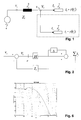
- FIG. 1 schematically shows an electrical network model.
- the model represents a number of distributed power generation (DPG) units 1,1' connected to a common bus 2 which in turn is connected through a transmission line 3 with impedance Z L to a stiff grid or power source 4.
- the DPG units 1,1' are similar to each other in that they show essentially the same electrical characteristics, as seen from the common bus 2. Only two DPG units 1,1' are depicted in the figure, however an arbitrary number of DPG units may be connected to the common bus 2.
- the object of the invention is to determine the maximum number of such DPG units in a computationally and efficient manner.
- the model elements DPG unit 1, common bus 2, transmission line 3 and stiff power source 4 give an abstract representation of any actual power network that can, with reasonable accuracy, be interpreted in terms of the structure of figure 1.
- the common bus 2 is a low voltage bus
- the stiff power source 4 is a medium or high voltage grid
- the transmission line impedance Z L comprises a transformer impedance.
- the stiff grid or power source 4 can both provide and absorb electrical power, i.e. it serves as both a power source and as a power sink, that is a source of negative power, according to circumstances.
- the stiff power source 4, together with the transmission line 3, represent a power grid from the point of view of the common bus 2.
- the DPG units 1,1' are replaced by arbitrary units such as loads with nontrivial, i.e. other than ohmic load characteristics, again under the conditions that all units are similar to each other, i.e. that the electrical load behaviour of each unit can be represented by the same mathematical model.
- the relationship expressed by the impedance Z L represents not a line 3 and stiff source 4 as shown in figure DPG unit 1, but a stiff source and an element that is representable by an impedance, such as an arbitrary power source or load with a known current to voltage characteristic.
- a combined system comprising the DPG units 1,1' and a power source or sink as represented by the transmission line 3 and the stiff power source 4 is considered.
- the object is to determine whether, if there is a bounded disturbance in the voltage V s of the stiff power source 4, the current through the transmission line, or alternatively the voltage V l at the common bus 2, remains bounded.
- the block diagram shown in figure 2 represents the relations between the electrical variables involved in figure 1.
- this relation is expressed by a linear transfer function matrix H that comprises transfer functions from components of the well-known dq-representation of the voltage at the unit to components of the dq-current through a unit.
- the number of DPG units 1,1' is expressed by a multiplicative factor ⁇ representing the number of additional DPG units with respect to a single DPG unit 1.
Landscapes
- Engineering & Computer Science (AREA)
- Power Engineering (AREA)
- Supply And Distribution Of Alternating Current (AREA)
Abstract
A method for determining a critical number of similar units (1,1') in
a power network comprises the steps of
- determining a single frequency domain representation representing each of a number of similar units (1,1'),
- determining a frequency domain representation of a power grid (3)
- determining a frequency domain representation of a combined system, where the combined system comprises all the similar units (1,1') and the power grid (3), where said frequency domain representation of the combined system has the number of similar units as a parameter,
- performing a robust stability analysis of the combined system, and
- determining an upper bound on the number of similar units (1,1') for which the combined system is stable.
Description
- The invention relates to the field of power system planning. It relates to a method, computer program and data processing system for determining a critical number of similar units in a power network as described in the preamble of
claim - With the opening of electrical power networks to relatively small, distributed power generation units, network stability problems arise. This gives rise to the new problem of assessing network stability for the case in which a large number of similar units, in particular generating units, are connected to the network. It is desirable to determine a maximum number of similar units that may be connected without causing the network to become unstable.
- Classical electrical network stability analysis focuses on the development of a set of differentiable algebraic equations. Then, stability is assumed if, i) the Jacobian of the algebraic system is invertable, i.e. if the algebraic equations have a solution, and ii) the linearised dynamic system as no positive Eigen values. This approach is primarily a trial and error method and gives no prior indication of any stability limits. Additionally such approaches require detailed modelling of the complete electrical system.
- It is therefore an object of the invention to create a method, computer program and data processing system for determining a critical number of similar units in a power network of the type mentioned initially, which overcomes the disadvantages mentioned above.
- These objects are achieved by a method, computer program and data processing system for determining a critical number of similar units in a power network according to the
claims - The inventive method thus comprises the steps of
- determining a single frequency domain representation representing each of a number of similar units,
- determining a frequency domain representation of a power source,
- determining a frequency domain representation of a combined system, where the combined system comprises all the similar units and the power source, where said frequency domain representation of the combined system has the number of similar units as a parameter,
- performing a robust stability analysis of the combined system, and
- determining an upper bound on the number of similar units for which the combined system is stable.
- The upper bound on the number of similar units is therefore found explicitly by a straightforward calculation. This is in contrast to a heuristic or iterative procedure in which the number of units is varied and the stability is determined repeatedly, until a maximum number is found for which the system is still stable.
- The computer program for determining a critical number of similar units in a power network according to the invention is loadable into an internal memory of a digital computer, and comprises computer program code means to make, when said computer program code means is loaded in the computer, the computer execute the method according to the invention. In a preferred embodiment of the invention, a computer program product comprises a computer readable medium, having the computer program code means recorded thereon.
- A data processing system for determining a critical number of similar units in a power network according to the invention comprises means for carrying out the steps of the method according to the invention. In a preferred embodiment of the invention, the data processing system is an apparatus comprising a data processor, a memory coupled to the processor and computer program code means stored in said memory, where said computer program code means, when executed by the processor, causes the method according to the invention to be executed.
- Further preferred embodiments are evident from the dependent patent claims.
- The subject matter of the invention will be explained in more detail in the following text with reference to preferred exemplary embodiments which are illustrated in the attached drawings, in which:
- Figure 1 schematically shows an electrical network model;
- Figure 2 shows a feedback model of the electrical network model;
- Figure 3 shows a sample generator unit transfer function matrix;
- Figure 4 shows a sample transmission line transfer function matrix;
- Figure 5 shows an intermediate result transfer function matrix; and
- Figure 6 shows a sample sequence of inverted largest singular values.
-
- The reference symbols used in the drawings, and their meanings, are listed in summary form in the list of reference symbols. In principle, identical parts are provided with the same reference symbols in the figures.
- Figure 1 schematically shows an electrical network model. The model represents a number of distributed power generation (DPG)
units 1,1' connected to acommon bus 2 which in turn is connected through atransmission line 3 with impedance ZL to a stiff grid orpower source 4. TheDPG units 1,1' are similar to each other in that they show essentially the same electrical characteristics, as seen from thecommon bus 2. Only twoDPG units 1,1' are depicted in the figure, however an arbitrary number of DPG units may be connected to thecommon bus 2. The object of the invention is to determine the maximum number of such DPG units in a computationally and efficient manner. - The model
elements DPG unit 1,common bus 2,transmission line 3 andstiff power source 4 give an abstract representation of any actual power network that can, with reasonable accuracy, be interpreted in terms of the structure of figure 1. In a preferred embodiment of the invention, thecommon bus 2 is a low voltage bus, thestiff power source 4 is a medium or high voltage grid, and the transmission line impedance ZL comprises a transformer impedance. The stiff grid orpower source 4 can both provide and absorb electrical power, i.e. it serves as both a power source and as a power sink, that is a source of negative power, according to circumstances. Thestiff power source 4, together with thetransmission line 3, represent a power grid from the point of view of thecommon bus 2. - In another preferred embodiment of the invention, the
DPG units 1,1' are replaced by arbitrary units such as loads with nontrivial, i.e. other than ohmic load characteristics, again under the conditions that all units are similar to each other, i.e. that the electrical load behaviour of each unit can be represented by the same mathematical model. - In another preferred embodiment of the invention, the relationship expressed by the impedance ZL represents not a
line 3 andstiff source 4 as shown infigure DPG unit 1, but a stiff source and an element that is representable by an impedance, such as an arbitrary power source or load with a known current to voltage characteristic. - In order to assess the stability, a combined system comprising the
DPG units 1,1' and a power source or sink as represented by thetransmission line 3 and thestiff power source 4 is considered. In control theoretic terms, the object is to determine whether, if there is a bounded disturbance in the voltage Vs of thestiff power source 4, the current through the transmission line, or alternatively the voltage Vl at thecommon bus 2, remains bounded. The block diagram shown in figure 2 represents the relations between the electrical variables involved in figure 1. Each of theplural DPG units 1,1' is represented by the same load or source characteristic, that is, by a voltage to current relation Il = f(Vl ). In a preferred embodiment of the invention, this relation is expressed by a linear transfer function matrix H that comprises transfer functions from components of the well-known dq-representation of the voltage at the unit to components of the dq-current through a unit. - The number of
DPG units 1,1' is expressed by a multiplicative factor Δ representing the number of additional DPG units with respect to asingle DPG unit 1. Having represented the combined system and the number ofDPG units 1,1' in the manner shown, it is now possible to apply specific results from robust stability analysis. Such an analysis, for a system representation having a given structure, gives bounds on given uncertain parameters for which stability of the system is ensured. For example M. Green and D. Limebeer, "Linear Robust Control", Prentice Hall Information and System Sciences Series, 1995, gives an upper-bound on the size of delta that guarantees loop stability. In the present case delta is a scalar, and the stability question reduces to identifying the bounds within which delta can vary without resulting in an unstable system. The result according to the theory cited above is conservative as it allows Δ to, depending on the frequency, vary in both phase and magnitude simultaneously, whereas the present case only considers a non-frequency dependent change in magnitude. While conservative, the result is still appropriate as it is an absolute lower bound and provides an additional error of margin for e.g. modelling errors. - Following the theory cited above the critical number Δ must satisfyor, since Δ is a scalar
 where
where
σ (A) denotes the largest singular value of A. - Various approaches are possible for checking the above condition. In a preferred embodiment of the invention of the method according to the invention, the following steps are performed:
- 1) Determining the dq-voltage to dq-current input-output relationship H of
the
DPG units 1,1'. H is a two-by-two transfer function matrix, i.e., a frequency dependent complex valued matrix for determining the unit current Il , represented in the frequency domain, from the unit voltage Vl , represented in the frequency domain. This step either comprises reading a computer representation of H from storage or determining H with an automatic frequency response measurement device. If the representation is read from storage, it has been determined e.g. by automatic or manual measurement or from first principles modelling. - 2) Determining a two-by-two transfer function matrix Zl ,, representing the
dq-current to dq-voltage input output relationship from the current Σ/ l
through the
transmission line 3 to the voltage Vl at thecommon bus 2. This is again done by either reading a computer representation from a computer storage and/or from automatically measuring or modelling the transmission line resistance and inductance. - 3) Computing Eigen values of the four-by-four transfer function matrix
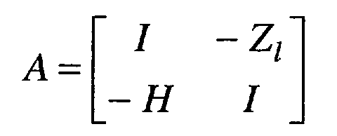
with / being the identity matrix, and determining whether the real part of each Eigen value is strictly negative. If this is the case, then the nominal configuration of the network with Δ equal to zero is stable. Otherwise, the nominal configuration with just one
DPG unit 1 is unstable and it is not possible or sensible to connect any additional DPG units 1'. - 4) Computing the two-by-two transfer function matrix
- 5) Repeatedly computing, with frequency varying stepwise from zero to some chosen upper bound, the value of the transfer function matrix B at said frequency, which gives, for each frequency, a complex valued two-by-two matrix. For each of this set of matrices, the largest singular value is computed, and the largest singular values are collected in a vector, C, of real numbers.
- 6) Inverting the elements of vector C and finding the smallest value. This value
is the upper bound on the number of DPG units represented by H that can
be connected to the
common bus 2. -
- The method is illustrated by way of the following example:
- 1) The transfer function matrix H for a micro-turbine unit is shown using Bode diagrams in Figure 3.
- 2) The transfer function matrix Zl for a short, low impedance, transmission line is shown in Figure 4.
- 3) The Eigen values of the A matrix are calculated as (values scaled byle-4),
- 3.8571e5
- 3.8571e5
- 2.5553 + 0.1144i
- 2.5553 - 0.1144i
- 1.5485 + 1.7142i
- 1.5485 - 1.7142i
- 1.4273 + 1.5311i
- 1.4273 - 1.5311i
- 1.0715
- 0.0305 + 0.0655i
- 0.0305 - 0.0655i
- 0.0005 + 0.0010i
- 0.0005 - 0.0010i
There are no zero or positive real components, therefore, execution of he method can continue
- 4) The transfer function matrix B is shown using Bode diagrams in Figure 5.
- 5) The collected largest singular values are inverted and shown, using a decibel y-axis scale, in Figure 6.
- 6) The smallest value is read off of Figure 6 giving a value of 21.
Therefore an upper bound of 11 < 1021/20 additional DPG units represented
by H can be connected to the common bus
common bus 2, giving a maximum number of 12 DPG units in total. -
-
- 1
- DPG unit
- 2
- common bus
- 3
- transmission line
- 4
- stiff power source
Claims (10)
- A method for determining a critical number of similar units in a power network, where each of the similar units is representable by the same electrical behaviour, characterized in that the method comprises the steps ofdetermining a single frequency domain representation representing each of the similar units,determining a frequency domain representation of a power grid,determining a frequency domain representation of a combined system, where the combined system comprises all the similar units and the power grid, said frequency domain representation of the combined system having the number of similar units as a parameter,performing a robust stability analysis of the combined system, anddetermining an upper bound on the number of similar units for which the combined system is stable.
- Method according to claim 1, wherein the similar units are power generation units.
- Method according to claim 1 or 2, wherein the similar units are connected to a common bus of the power network.
- Method according to claim 3, wherein the representation of the power source represents a transmission line connecting said common bus to a stiff power source.
- Method according to claim 3, wherein the representation of the power source represents a characteristic or one of a power source or load.
- Method according to claim 1, wherein the upper bound on the number of similar units is a conservative estimate.
- Method according to claim 1, wherein a representation of all the similar units is obtained as a multiplicative variation of the representation of a single one of the units.
- Method according to claim 1, wherein the frequency domain representation representing each of the similar units, is a transfer function matrix H relating unit voltage to unit current,
the frequency domain representation of the power source is a transfer function matrix Zl relating source current to source voltage,
and the upper bound on the number of similar units is determined as being the closest integer smaller thanwhere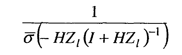
σ (.) denotes the largest singular value and / an identity matrix. - Computer program for determining a critical number of similar units in a power network which is loadable and executable on a data processing unit and which computer program, when being executed, performs the steps according to one of the preceding claims.
- Data processing system for determining a critical number of similar units in a power network comprising means for carrying out the steps of the method according to any one of the claims 1 to 8.
Priority Applications (1)
| Application Number | Priority Date | Filing Date | Title |
|---|---|---|---|
| EP20020405871 EP1408597A1 (en) | 2002-10-10 | 2002-10-10 | Determining a critical number of similar units in a power network |
Applications Claiming Priority (1)
| Application Number | Priority Date | Filing Date | Title |
|---|---|---|---|
| EP20020405871 EP1408597A1 (en) | 2002-10-10 | 2002-10-10 | Determining a critical number of similar units in a power network |
Publications (1)
| Publication Number | Publication Date |
|---|---|
| EP1408597A1 true EP1408597A1 (en) | 2004-04-14 |
Family
ID=32011059
Family Applications (1)
| Application Number | Title | Priority Date | Filing Date |
|---|---|---|---|
| EP20020405871 Withdrawn EP1408597A1 (en) | 2002-10-10 | 2002-10-10 | Determining a critical number of similar units in a power network |
Country Status (1)
| Country | Link |
|---|---|
| EP (1) | EP1408597A1 (en) |
-
2002
- 2002-10-10 EP EP20020405871 patent/EP1408597A1/en not_active Withdrawn
Non-Patent Citations (6)
| Title |
|---|
| "Power System Blockset 2", 2001, MATHWORKS, XP002232402 * |
| "Robust Control Toolbox 2.0", 1996, MATHWORKS, XP002232403 * |
| "Simulink 5", September 2002, MATHWORKS, XP002232404 * |
| DJUKANOVIC M ET AL: "Application of the structured singular value theory for robust stability and control analysis in multimachine power systems. I. Framework development", IEEE TRANSACTIONS ON POWER SYSTEMS, NOV. 1998, IEEE, USA, vol. 13, no. 4, pages 1311 - 1316, XP002232399, ISSN: 0885-8950 * |
| LEI X ET AL: "Industrial approaches for dynamic equivalents of large power systems", 2002 IEEE POWER ENGINEERING SOCIETY. WINTER MEETING. CONFERENCE PROCEEDINGS. NEW YORK, NY, JAN. 27 - 31, 2002, IEEE POWER ENGINEERING SOCIETY, NEW YORK, NY: IEEE, US, vol. 2 OF 2, 27 January 2002 (2002-01-27), pages 1036 - 1042, XP010578447, ISBN: 0-7803-7322-7 * |
| WANG L ET AL: "Dynamic reduction of large power systems for stability studies", IEEE TRANSACTIONS ON POWER SYSTEMS, MAY 1997, IEEE, USA, vol. 12, no. 2, pages 889 - 895, XP002232400, ISSN: 0885-8950 * |
Similar Documents
| Publication | Publication Date | Title |
|---|---|---|
| Hu et al. | Linear parameter varying battery model identification using subspace methods | |
| Mueller et al. | Modeling dual active bridge converters in DC distribution systems | |
| US20040083087A1 (en) | Simulation of an electrical power transmission network | |
| Smith et al. | Model validation for dynamically uncertain systems | |
| Sarić et al. | Symbolic regression for data-driven dynamic model refinement in power systems | |
| Lind et al. | Distribution system modelling for voltage stability studies | |
| Rayyam et al. | A new metaheuristic unscented Kalman filter for state vector estimation of the induction motor based on Ant Lion optimizer | |
| Chassin et al. | Load modeling and calibration techniques for power system studies | |
| Zarate et al. | Fast computation of security margins to voltage collapse based on sensitivity analysis | |
| EP1408597A1 (en) | Determining a critical number of similar units in a power network | |
| Bakeer et al. | Robust operation of four-leg voltage source inverter using model-free predictive control | |
| Patra et al. | Probabilistic load flow solution using method of moments | |
| Salam et al. | Adaptive neural observer with forward co-state propagation | |
| CN117937477B (en) | Method and device for predicting reactive power boundary value of generator set and computer equipment | |
| Smith et al. | Validation of continuous-time control models by finite experimental data | |
| Herber et al. | Approximating arbitrary impulse response functions with Prony basis functions | |
| KR102512544B1 (en) | Battery equivalent circuit generation method and apparatus | |
| CN117607520A (en) | Current sampling method, device and medium of current transformer in nonlinear region | |
| Sawhney et al. | On-line transient stability assessment using artificial neural network | |
| Sankhe et al. | Overview of Power Hardware-in-the-Loop Simulation Towards Implementation of Digital Controller for Resonant Inverters | |
| Pereira et al. | Combining fuzzy and probabilistic data in power system state estimation | |
| Tahami et al. | Piecewise affine system modeling and control of PWM converters | |
| Athanasiou et al. | On the efficient simulation of electrical circuits with constant phase elements: The Warburg element as a test case | |
| US7212934B1 (en) | String resistance detector | |
| Agundis-Tinajero et al. | Performance assessment of shooting methods using parallel cloud computing |
Legal Events
| Date | Code | Title | Description |
|---|---|---|---|
| PUAI | Public reference made under article 153(3) epc to a published international application that has entered the european phase |
Free format text: ORIGINAL CODE: 0009012 |
|
| AK | Designated contracting states |
Kind code of ref document: A1 Designated state(s): AT BE BG CH CY CZ DE DK EE ES FI FR GB GR IE IT LI LU MC NL PT SE SK TR |
|
| AX | Request for extension of the european patent |
Extension state: AL LT LV MK RO SI |
|
| AKX | Designation fees paid | ||
| REG | Reference to a national code |
Ref country code: DE Ref legal event code: 8566 |
|
| STAA | Information on the status of an ep patent application or granted ep patent |
Free format text: STATUS: THE APPLICATION IS DEEMED TO BE WITHDRAWN |
|
| 18D | Application deemed to be withdrawn |
Effective date: 20041015 |