EP1408486A1 - Head drum assemblies - Google Patents
Head drum assemblies Download PDFInfo
- Publication number
- EP1408486A1 EP1408486A1 EP20030256190 EP03256190A EP1408486A1 EP 1408486 A1 EP1408486 A1 EP 1408486A1 EP 20030256190 EP20030256190 EP 20030256190 EP 03256190 A EP03256190 A EP 03256190A EP 1408486 A1 EP1408486 A1 EP 1408486A1
- Authority
- EP
- European Patent Office
- Prior art keywords
- shaft
- drum
- bearing
- bearings
- assembly
- Prior art date
- Legal status (The legal status is an assumption and is not a legal conclusion. Google has not performed a legal analysis and makes no representation as to the accuracy of the status listed.)
- Withdrawn
Links
Images



Classifications
-
- G—PHYSICS
- G11—INFORMATION STORAGE
- G11B—INFORMATION STORAGE BASED ON RELATIVE MOVEMENT BETWEEN RECORD CARRIER AND TRANSDUCER
- G11B15/00—Driving, starting or stopping record carriers of filamentary or web form; Driving both such record carriers and heads; Guiding such record carriers or containers therefor; Control thereof; Control of operating function
- G11B15/60—Guiding record carrier
- G11B15/61—Guiding record carrier on drum, e.g. drum containing rotating heads
-
- G—PHYSICS
- G11—INFORMATION STORAGE
- G11B—INFORMATION STORAGE BASED ON RELATIVE MOVEMENT BETWEEN RECORD CARRIER AND TRANSDUCER
- G11B5/00—Recording by magnetisation or demagnetisation of a record carrier; Reproducing by magnetic means; Record carriers therefor
- G11B5/48—Disposition or mounting of heads or head supports relative to record carriers ; arrangements of heads, e.g. for scanning the record carrier to increase the relative speed
- G11B5/52—Disposition or mounting of heads or head supports relative to record carriers ; arrangements of heads, e.g. for scanning the record carrier to increase the relative speed with simultaneous movement of head and record carrier, e.g. rotation of head
- G11B5/53—Disposition or mounting of heads on rotating support
- G11B5/531—Disposition of more than one recording or reproducing head on support rotating cyclically around an axis
Definitions
- the present invention relates to a head drum assembly for a tape recorder, comprising: a shaft; and a drum connected to the shaft by first and second separated bearings, and to a method of fabricating a head drum assembly, comprising: fitting a first bearing into a drum; fitting a shaft through the first bearing; and fitting a second bearing around the shaft.
- FIG. 1 is a partial cross-sectional schematic view of a head drum assembly.
- the head drum assembly comprises: a rotary drum 10, which rotatably supports a magnetic head H for recording/reproducing information by scanning a running magnetic tape; a fixed drum 20, which is press-fitted onto a lower part of a shaft 30 engaged in a central axial bore of the rotary drum 10; an upper bearing 40 and a lower bearing 50 press-fitted between the rotary drum 10 and the shaft 30.
- the head drum assembly is provided with preloading means for applying preload to the upper bearing 40 and the lower bearing 50.
- a preloading boss 60 is provided above the upper bearing 40, and a rib 70 is provided on the fixed drum 20 below the lower bearing 50.
- the preloading boss 60 is secured by a set screw S so that a projection formed in the preloading boss 60 downwardly compresses the innermost race 41 of the upper bearing 40.
- the rib 70 upwardly compresses the inner race 51 of the lower bearing, thereby applying preload to the bearings.
- the head drum assembly be subjected to a heat treatment process (such as annealing) after the bearings are assembled. This step reduces the manufacturing yield.
- the rotary drum 110 supports a magnetic head H for recording and reproducing information by scanning a running magnetic tape.
- the fixed drum 120 is engaged on an axial bore of the rotary drum 110, parallel to the rotary drum.
- the bearings 140, 150 are provided between the rotary drum 110 and the shaft 130.
- the preloading means 160 comprises an elastic body mounted on the circumferential surface of the shaft 130 and interposed between the inner races 141, 151 of the upper and lower bearings 140 and 150.
- the preloading means 160 can be formed from a coil spring in compression, as shown. However, the preloading means can take any other suitable form, as will be appreciated by the person skilled in the art. The main requirement of the preloading means is to effect compression of the bearings 140, 150.
- the outer diameter of the shaft 130 is somewhat larger than the inner diameter of the inner race 141 of the upper bearing 140. This results in the inner race 141 of the upper bearing 140 being tightly fitted with and bonded to the outer diameter of the shaft 130.
- the elastic body 160 e.g., a compression coil spring
- the lower bearing 150 is fitted into the lower part of the rotary drum 110, so that the inner race 151 of the lower bearing 150 supports the lower end of the elastic body 160 as shown in Figure 3D.
- the elastic body 160 is installed to support and bias elastically the inner race 141 of the upper bearing 140 upwardly as shown in Figure 3C. As a result, a third assembly 100c is formed. This results in a balanced state in the head drum assembly.
- the lower bearing 150 is press-fitted onto the shaft 130 and then press-fitted into a recess 122 formed in the central part of the bottom surface of the rotary drum 110.
- the inner race 151 of the lower bearing 150 comes into close contact with the circumferential outer surface of the shaft 130, and the elastic body 160 compresses and elastically biases the inner race 151 downwardly.
- the elastic body 160 respectively compresses the inner race 141 of the upper bearing 140 and the inner race 151 of the lower bearing 150 upwardly and downwardly respectively, as a result of which preload is applied to the bearings in the directions indicated by the arrows shown in Figure 2.
Landscapes
- Support Of The Bearing (AREA)
Abstract
Description
- The present invention relates to a head drum assembly for a tape recorder, comprising: a shaft; and a drum connected to the shaft by first and second separated bearings, and to a method of fabricating a head drum assembly, comprising: fitting a first bearing into a drum; fitting a shaft through the first bearing; and fitting a second bearing around the shaft.
- In general, tape recorders such as VCRs and camcorders are provided with a head drum assembly that is mounted for high-speed rotation. This enables information to be recorded and reproduced by the scanning of a magnetic head in relation to a magnetic tape. Figure 1 is a partial cross-sectional schematic view of a head drum assembly. As shown, the head drum assembly comprises: a
rotary drum 10, which rotatably supports a magnetic head H for recording/reproducing information by scanning a running magnetic tape; afixed drum 20, which is press-fitted onto a lower part of ashaft 30 engaged in a central axial bore of therotary drum 10; an upper bearing 40 and a lower bearing 50 press-fitted between therotary drum 10 and theshaft 30. An inner race of each bearing 40, 50 is located in theshaft 30 and an outer race of each is press-fitted into therotary drum 10. Arotor 1 and astator 2 are arranged relative to amagnet 3, which is mounted on the internal circumferential surface of therotor 1. - The head drum assembly is provided with preloading means for applying preload to the upper bearing 40 and the
lower bearing 50. In particular, a preloadingboss 60 is provided above the upper bearing 40, and arib 70 is provided on the fixeddrum 20 below thelower bearing 50. The preloadingboss 60 is secured by a set screw S so that a projection formed in the preloadingboss 60 downwardly compresses theinnermost race 41 of the upper bearing 40. Therib 70 upwardly compresses theinner race 51 of the lower bearing, thereby applying preload to the bearings. - There is a cost involved in providing the preloading
boss 60 and the set screw. Also, because it is not easy to determine the position for securing the preloadingboss 60 when engaging the set screw S, it is difficult to precisely control the preload. This can lead to the generation of noise while driving the bearings. - Furthermore, to remove thermal deformation caused by the excessive press-fitting of the bearings, it is required that the head drum assembly be subjected to a heat treatment process (such as annealing) after the bearings are assembled. This step reduces the manufacturing yield.
- An aim of the present invention is to ameliorate or overcome these disadvantages.
- The head drum assembly according to the invention is characterised by resilient preloading means for applying preload to the first and second bearings.
- The method according to the invention is characterised by resilient preloading means to preload the bearings.
- The invention will now be described by way of example only with reference to the accompanying drawings, in which:
- Figure 1 is a partial cross-sectional schematic view of a conventional head drum assembly of a tape recorder;
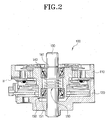
- Figure 2 is a cross-sectional schematic view of a head drum assembly according to the present invention; and
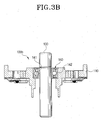
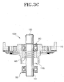
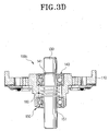
- Figures 3A to 3E illustrate a method of assembling the Figure 2 head drum assembly.
-
- Referring to Figure 2, the
head drum assembly 100 of a tape recorder according to the invention comprises: arotary drum 110, a fixeddrum 120 press-fitted onto a lower part of ashaft 130, an upper bearing 140 and alower bearing 150 havinginner races - The
rotary drum 110 supports a magnetic head H for recording and reproducing information by scanning a running magnetic tape. Thefixed drum 120 is engaged on an axial bore of therotary drum 110, parallel to the rotary drum. Thebearings rotary drum 110 and theshaft 130. The preloading means 160 comprises an elastic body mounted on the circumferential surface of theshaft 130 and interposed between theinner races lower bearings - The
elastic body 160 compresses theinner race 141 of the upper bearing 140 and theinner race 151 of thelower bearing 150 upward and downward, respectively, to effect preloading of the upper andlower bearings - The preloading means 160 can be formed from a coil spring in compression, as shown. However, the preloading means can take any other suitable form, as will be appreciated by the person skilled in the art. The main requirement of the preloading means is to effect compression of the
bearings - A description will now be given of the method of assembling the Figure 2 head drum assembly, with reference to Figures 3A to 3E.
- Initially, the upper bearing 140 is vertically downwardly and forcibly press-fitted into a
recess 110a formed in the central part of the top surface of therotary bearing 110, thereby forming afirst assembly 100a as shown in Figure 3A. Here, theouter race 142 of the upper bearing 140 comes into close contact with the internal circumferential surface of therecess 110a and is upwardly compressed. Therefore, the upper bearing is maintained in a finely raised state. - As shown in Figure 3B, the
shaft 130 is then fitted into the upper bearing 140 of thefirst assembly 100a, thereby forming asecond assembly 100b. - The outer diameter of the
shaft 130 is somewhat larger than the inner diameter of theinner race 141 of the upper bearing 140. This results in theinner race 141 of the upper bearing 140 being tightly fitted with and bonded to the outer diameter of theshaft 130. - As shown in Figures 3C and 3D, the
elastic body 160, e.g., a compression coil spring, is then installed as a preloading means. Thelower bearing 150 is fitted into the lower part of therotary drum 110, so that theinner race 151 of thelower bearing 150 supports the lower end of theelastic body 160 as shown in Figure 3D. Theelastic body 160 is installed to support and bias elastically theinner race 141 of the upper bearing 140 upwardly as shown in Figure 3C. As a result, athird assembly 100c is formed. This results in a balanced state in the head drum assembly. - In forming the
third assembly 100c, thelower bearing 150 is press-fitted onto theshaft 130 and then press-fitted into a recess 122 formed in the central part of the bottom surface of therotary drum 110. Here, theinner race 151 of thelower bearing 150 comes into close contact with the circumferential outer surface of theshaft 130, and theelastic body 160 compresses and elastically biases theinner race 151 downwardly. As such, theelastic body 160 respectively compresses theinner race 141 of the upper bearing 140 and theinner race 151 of thelower bearing 150 upwardly and downwardly respectively, as a result of which preload is applied to the bearings in the directions indicated by the arrows shown in Figure 2. - Instead, the
lower bearing 150 may be fitted onto the shaft such that theinner race 151 is moveable along the shaft. - Finally, referring to Figure 3E, the
fixed drum 120 is press-fitted onto theshaft 130 below therotary drum 110 of thethird assembly 100c. This completes the head drum assembly. - With this head drum assembly, a preloading boss and a screw for securing the boss are not required. Furthermore, it is also possible to omit the annealing step for removing thermal deformation caused in the manufacturing process. Thus, the cost of making the embodied head drum assembly can be less than that of making the described prior art assembly.
- The invention is not limited to the embodiment described above, and variants will be envisaged by those skilled in the art without departing from the scope of the invention as defined by the claims. For example, other ways of applying the preload to the upper and
lower bearings
Claims (29)
- A head drum assembly of a tape recorder, comprising:a shaft;a rotary drum which supports a magnetic head for recording and reproducing information by scanning a running magnetic tape;a fixed drum, press-fitted onto a lower part of the shaft, engaged on an axial bore of the rotary drum, parallel to the rotary drum;an upper bearing and a lower bearing, provided one on the other between the rotary drum and the shaft; andpreloading means for applying preload to the upper and lower bearings.
- The head drum assembly of a tape recorder according to claim 1, wherein the upper and lower bearings each comprise an inner race, and wherein the preloading means comprises an elastic body mounted on the circumferential surface of the shaft and interposed between the upper and lower bearings to elastically bias and compress each of the inner races of the upper and lower bearings.
- The head drum assembly of a tape recorder, wherein the elastic body comprises a spring.
- A head drum assembly of a tape recorder, comprising:a shaft;a rotary drum which supports a magnetic head for recording and reproducing information by scanning a running magnetic tape;a fixed drum, press-fitted onto a lower part of the shaft, engaged on an axial bore of the rotary drum, parallel to the rotary drum;an upper bearing and a lower bearing, provided one on the other between the rotary drum and the shaft; anda preload apparatus which applies a preload to the upper and lower bearings.
- The head drum assembly of a tape recorder according to claim 4, wherein the upper and lower bearings each comprises an inner race, and wherein the preloading apparatus comprises an elastic body mounted on the circumferential surface of the shaft and interposed between the upper and lower bearings to elastically bias and compress each of the inner races of the upper and lower bearings.
- The head drum assembly of a tape recorder according to claim 5, wherein the elastic body comprises a spring.
- The head drum assembly of a tape recorder according to claim 4, wherein the rotary drum further comprises an upper recess for accepting the upper bearing and a lower recess for accepting the lower bearing.
- The head drum assembly of a tape recorder according to claim 4, wherein the preload is applied to the inner race of the upper bearing in an upward direction,
- The head drum assembly of a tape recorder according to claim 4, wherein the preload is applied to the inner race of the lower bearing in a downward direction.
- The head drum assembly of a tape recorder according to claim 4, further comprising a fixed drum pressure fitted onto the shaft.
- A method for fabricating a head drum assembly of a tape recorder, comprising:press fitting an upper bearing into an upper recess of a rotary drum, which supports a magnetic head for recording and reproducing information by scanning a running magnetic tape;press fitting a shaft through the upper bearing;inserting preloading means around the shaft adjacent to a lower surface of the upper bearing;press fitting a lower bearing around the shaft into a lower recess of the rotary drum, such that the preloading means is elastically biased against the upper and lower bearings; andpress fitting a fixed drum around the shaft, lower bearing and rotating drum.
- The method according to claim 11, wherein the preload means comprises a spring.
- The method according to claim 11, wherein the preload is applied to an inner race of the upper bearing in an upward direction, and the preload is applied to an inner race of the lower bearing in a downward direction.
- A method for fabricating a head drum assembly of a tape recorder, comprising:press fitting an upper bearing into an upper recess of a rotary drum, which supports a magnetic head for recording and reproducing information by scanning a running magnetic tape;press fitting a shaft through the upper bearing;inserting a preloading apparatus around the shaft adjacent to a lower surface of the upper bearing;press fitting a lower bearing around the shaft into a lower recess of the rotary drum, such that the preloading means is elastically biased against the upper and lower bearings; andpress fitting a fixed drum around the shaft, lower bearing and rotating drum.
- The method according to claim 14, wherein the preload apparatus comprises a spring.
- The method according to claim 14, wherein the preload is applied to an inner race of the upper bearing in an upward direction, and the preload is applied to an inner race of the lower bearing in a downward direction.
- A head drum assembly for a tape recorder, comprising:characterised by resilient preloading means (160) for applying preload to the first and second bearings.a shaft (130); anda drum (110) connected to the shaft by first and second separated bearings (140, 150),
- An assembly according to claim 17, wherein the preloading means is interposed between the bearings.
- An assembly according to claim 17 or claim 18, in which the preloading means contacts inner races (141, 151) of the bearings.
- An assembly according to any of claims 17 to 19, wherein the preloading means comprises a compression spring.
- An assembly as claimed in any of claims 17 to 20, in which the bearings are situated in recesses in the drum, the recesses having substantially opposite-facing openings.
- An assembly as claimed in claim 21, in which outer races of the bearings are press-fitted into the recesses.
- An assembly as claimed in any of claims 17 to 22, further comprising a second drum (120) pressure-fitted onto the shaft.
- An assembly as claimed in any of claims 17 to 23, in which the drum supports a magnetic head.
- A method of fabricating a head drum assembly, comprising:characterised by including resilient preloading means (160) to preload the bearings.fitting a first bearing (140) into a drum (110);fitting a shaft (130) through the first bearing; andfitting a second bearing (150) around the shaft,
- A method according to claim 25, comprising inserting the resilient preloading means between the first and second bearings.
- A method according to claim 25 or claim 26, wherein the preloading means contacts an inner race of one or both of the bearings.
- A method according to any of claims 25 to 27, wherein the preloading means comprises a compression spring.
- A method according to any of claims 25 to 28, further comprising fitting a second drum (120) on the shaft opposite the second bearing to the first bearing.
Applications Claiming Priority (2)
| Application Number | Priority Date | Filing Date | Title |
|---|---|---|---|
| KR2002061087 | 2002-10-07 | ||
| KR10-2002-0061087A KR100465165B1 (en) | 2002-10-07 | 2002-10-07 | A head drum assembly of tape recorder |
Publications (1)
| Publication Number | Publication Date |
|---|---|
| EP1408486A1 true EP1408486A1 (en) | 2004-04-14 |
Family
ID=32026126
Family Applications (1)
| Application Number | Title | Priority Date | Filing Date |
|---|---|---|---|
| EP20030256190 Withdrawn EP1408486A1 (en) | 2002-10-07 | 2003-09-30 | Head drum assemblies |
Country Status (5)
| Country | Link |
|---|---|
| US (1) | US7054112B2 (en) |
| EP (1) | EP1408486A1 (en) |
| JP (1) | JP4000309B2 (en) |
| KR (1) | KR100465165B1 (en) |
| CN (2) | CN1324564C (en) |
Families Citing this family (3)
| Publication number | Priority date | Publication date | Assignee | Title |
|---|---|---|---|---|
| CN1497538A (en) * | 2002-10-07 | 2004-05-19 | 三星电子株式会社 | Head Drum Parts for Tape Recorders |
| KR20050051858A (en) * | 2003-11-28 | 2005-06-02 | 삼성전자주식회사 | Head drum assembly of a tape recorder and method for assembling the same |
| KR20140070902A (en) * | 2012-11-29 | 2014-06-11 | 삼성전기주식회사 | Shaft combination module of motor ane the manufacturing method |
Citations (4)
| Publication number | Priority date | Publication date | Assignee | Title |
|---|---|---|---|---|
| EP0507281A2 (en) * | 1991-04-01 | 1992-10-07 | Sony Corporation | Magnetic head drum for video data recording and reading apparatus |
| GB2273810A (en) * | 1992-12-23 | 1994-06-29 | Samsung Electronics Co Ltd | Rotary head drum assembly |
| US5870257A (en) * | 1996-05-21 | 1999-02-09 | Daewoo Electronics Co., Ltd. | Head drum assembly for use in a digital video cassette recorder |
| US5949620A (en) * | 1996-03-22 | 1999-09-07 | Sharp Kabushiki Kaisha | Magnetic head drum assembly |
Family Cites Families (12)
| Publication number | Priority date | Publication date | Assignee | Title |
|---|---|---|---|---|
| DE1958645A1 (en) * | 1968-11-26 | 1970-07-30 | Matsushita Electric Ind Co Ltd | Pedal crank bearings for bicycles |
| GB2179407B (en) * | 1985-07-22 | 1990-01-04 | Alps Electric Co Ltd | Rotary head mechanism |
| JPS6416163A (en) | 1987-07-10 | 1989-01-19 | Canon Kk | Communication equipment |
| JPH01144201A (en) * | 1987-11-30 | 1989-06-06 | Nec Home Electron Ltd | Method for assembling head drum |
| JP2657585B2 (en) * | 1990-12-19 | 1997-09-24 | アルプス電気株式会社 | Rotary head device used for tape players |
| JPH04305814A (en) * | 1991-04-01 | 1992-10-28 | Sony Corp | Rotary head drum device |
| JPH0528405A (en) * | 1991-07-26 | 1993-02-05 | Sony Corp | Rotating head drum device |
| JPH06259703A (en) * | 1993-03-04 | 1994-09-16 | Sony Corp | Rotary head drum |
| KR960015995B1 (en) * | 1993-07-31 | 1996-11-25 | 대우전자 주식회사 | Head Drum Unit of Tape Recorder |
| KR19980034906U (en) * | 1996-12-11 | 1998-09-15 | 김광호 | Head Drum Assembly of Tape Recorder |
| JP2000057544A (en) | 1998-08-04 | 2000-02-25 | Alps Electric Co Ltd | Rotary head device |
| JP2001344721A (en) * | 2000-06-02 | 2001-12-14 | Matsushita Electric Ind Co Ltd | Rotating head drum device |
-
2002
- 2002-10-07 KR KR10-2002-0061087A patent/KR100465165B1/en not_active Expired - Fee Related
-
2003
- 2003-09-28 CN CNB031602517A patent/CN1324564C/en not_active Expired - Fee Related
- 2003-09-28 CN CNA2006101721366A patent/CN1983393A/en active Pending
- 2003-09-30 JP JP2003340904A patent/JP4000309B2/en not_active Expired - Fee Related
- 2003-09-30 EP EP20030256190 patent/EP1408486A1/en not_active Withdrawn
- 2003-10-06 US US10/678,069 patent/US7054112B2/en not_active Expired - Fee Related
Patent Citations (4)
| Publication number | Priority date | Publication date | Assignee | Title |
|---|---|---|---|---|
| EP0507281A2 (en) * | 1991-04-01 | 1992-10-07 | Sony Corporation | Magnetic head drum for video data recording and reading apparatus |
| GB2273810A (en) * | 1992-12-23 | 1994-06-29 | Samsung Electronics Co Ltd | Rotary head drum assembly |
| US5949620A (en) * | 1996-03-22 | 1999-09-07 | Sharp Kabushiki Kaisha | Magnetic head drum assembly |
| US5870257A (en) * | 1996-05-21 | 1999-02-09 | Daewoo Electronics Co., Ltd. | Head drum assembly for use in a digital video cassette recorder |
Also Published As
| Publication number | Publication date |
|---|---|
| CN1324564C (en) | 2007-07-04 |
| US7054112B2 (en) | 2006-05-30 |
| US20040066584A1 (en) | 2004-04-08 |
| JP4000309B2 (en) | 2007-10-31 |
| CN1983393A (en) | 2007-06-20 |
| CN1497539A (en) | 2004-05-19 |
| KR20040031536A (en) | 2004-04-13 |
| JP2004134066A (en) | 2004-04-30 |
| KR100465165B1 (en) | 2005-01-13 |
Similar Documents
| Publication | Publication Date | Title |
|---|---|---|
| US20020047394A1 (en) | Spindle motor | |
| EP1408486A1 (en) | Head drum assemblies | |
| US8148882B2 (en) | Spindle motor | |
| EP1408485A2 (en) | Head drum assembly for a tape recorder | |
| JP2014160521A (en) | Swing arm, information recording and reproduction system, and assembly method for swing arm | |
| US6582129B2 (en) | Compound bearing apparatus, and spindle motor and swing arm for hard disk drive means including such bearing apparatus | |
| KR100465336B1 (en) | A head drum assembly of tape recorder | |
| JPH0850743A (en) | Rotating drum device | |
| KR20040036312A (en) | A head drum assembly of tape recorder | |
| JPH0779550A (en) | Spindle motor assembly method | |
| KR100513856B1 (en) | A head drum assembly of tape recorder | |
| KR20050051858A (en) | Head drum assembly of a tape recorder and method for assembling the same | |
| JP2002213470A (en) | Rolling bearing device | |
| JP2006012397A (en) | Method for assembling head drum assembly of magnetic recording / reproducing apparatus | |
| KR20060000017A (en) | Head drum assembly, magnetic recording / playback apparatus having same and assembly method of head drum assembly | |
| JP2002031133A (en) | Shaft support structure and rotary drum device | |
| KR20040053688A (en) | a head-drum assembly of a magnetic record apparatus and a assembling method of a head-drum assembly | |
| KR200160878Y1 (en) | Head drum assembly | |
| KR890005009B1 (en) | Small size head drum for video tape recorder | |
| JP2000249141A (en) | Rotary drum device and method of assembling the same | |
| JP2000030322A (en) | Reel motor of magnetic recording / reproducing device | |
| JP2003161316A (en) | Head stack assembly and method of mounting bearing unit to head stack assembly | |
| KR20060020836A (en) | Manufacturing method of tape guide device of magnetic recording / playback device | |
| KR20060020838A (en) | Manufacturing method of tape guide device of magnetic recording / playback device | |
| JP2000262007A (en) | Disc drive motor |
Legal Events
| Date | Code | Title | Description |
|---|---|---|---|
| PUAI | Public reference made under article 153(3) epc to a published international application that has entered the european phase |
Free format text: ORIGINAL CODE: 0009012 |
|
| AK | Designated contracting states |
Kind code of ref document: A1 Designated state(s): AT BE BG CH CY CZ DE DK EE ES FI FR GB GR HU IE IT LI LU MC NL PT RO SE SI SK TR |
|
| AX | Request for extension of the european patent |
Extension state: AL LT LV MK |
|
| 17P | Request for examination filed |
Effective date: 20040522 |
|
| RAP1 | Party data changed (applicant data changed or rights of an application transferred) |
Owner name: SAMSUNG ELECTRONICS CO., LTD. |
|
| AKX | Designation fees paid |
Designated state(s): DE GB IT NL |
|
| STAA | Information on the status of an ep patent application or granted ep patent |
Free format text: STATUS: THE APPLICATION HAS BEEN WITHDRAWN |
|
| 18W | Application withdrawn |
Effective date: 20080814 |